Article

Development of a Novel High-Temperature Al Alloy for Laser Powder Bed Fusion

1
Department of Mechanical Engineering, Politecnico di Milano, Via G. La Masa 1, 20156 Milano, Italy
2
Beam-IT, Strada Prinzera, 17, 43045 Fornovo di Taro (PR), Italy
*
Author to whom correspondence should be addressed.
Metals 2021, 11(1), 35; https://doi.org/10.3390/met11010035
Submission received: 4 November 2020 / Revised: 14 December 2020 / Accepted: 22 December 2020 / Published: 26 December 2020
(This article belongs to the Special Issue Materials for Sustainable Beam-Based Additive Manufacturing)

Abstract

:
The number of available materials for Laser Powder Bed Fusion is still limited due to the poor processability of many standard alloys. In particular, the lack of high-strength aluminium alloys, widely used in aerospace and automotive industries, remains a big issue for the spread of beam-based additive manufacturing technologies. In this study, a novel high-strength aluminium alloy for high temperature applications having good processability was developed. The design of the alloy was done based on the chemical composition of the widely used EN AW 2618. This Al-Cu-Mg-Ni-Fe alloy was modified with Ti and B in order to promote the formation of TiB2 nuclei in the liquid phase able to stimulate heterogeneous nucleation of grains and to decrease the hot cracking susceptibility of the material. The new Al alloy was manufactured by gas atomisation and processed by Laser Powder Bed Fusion. Samples produced with optimised parameters featured relative density of 99.91%, with no solidification cracks within their microstructure. After aging, the material revealed upper yield strength and ultimate tensile strength of 495 MPa and 460 MPa, respectively. In addition, the alloy showed tensile strength higher than wrought EN AW 2618 at elevated temperatures.

1. Introduction

Additive Manufacturing (AM) is considered as a disruptive production process due to its ability to manufacture parts with complex geometry and small amount of waste. Several AM technologies have been developed during the recent years, the most widespread for the production of prototypes and small series is the Laser Powder Bed Fusion (L-PBF) [1]. L-PBF involves selective melting of a metallic powder bed and rapid solidification of tiny melt pools. Although there is a strong request for a wide range of alloys for L-PBF, the number of available materials on the market is still limited. Many alloys are indeed barely processable by L-PBF; in particular, many high strength Al alloys that belong to the 2xxx, 6xxx and 7xxx series have high susceptibility to hot cracking [2,3,4].
Hot cracking, also called hot tearing, is a well-known metallurgical phenomenon that can occur in casting and welding of many metallic materials, including high-strength Al alloys [5]. During the terminal stages of solidification, thermal shrinkage promotes build-up of tensile stresses in the semi-solid metal, causing nucleation and propagation of cracks along grain boundaries.
The development of high-strength Al alloys able to be processed by laser-based AM is considered as one of the big challenge to be faced for a wider spread of these technologies [6].
A few works on the modification of chemical composition of high-strength Al alloys have been recently published. Montero Sistiaga et al. tailored the chemical composition of the 7075 Al alloy by adding 4 wt.% of Si that led to an increase of material relative density and a reduction of solidification cracks. Casati et al. [7] designed and processed by L-PBF an Al-Zn-Si-Mg-Cu alloy. The alloy showed a relative density of 99.8%, a microstructure free of cracks and a tensile strength of 449 MPa. A few other research works focused on the effect of the addition of nucleants on the solidification behaviour of Al alloys processed by L-PBF [6,8,9]. Martin et al. showed that the addition of 1 vol.% Zr in 7075 and 6061 gas-atomised powders leads to uniform equiaxed grain structure with no cracks within the microstructure of L-PBF processed materials. In Ref. [8], L-PBF was used to fabricate Al-Cu-Mg and Al-Cu-Mg-Zr specimens. The hot cracking phenomenon was significantly reduced by the grain refining effect triggered by the addition of Zr. Finally, Wang et. al. investigated the positive effect of 5 vol.% of TiB2 particles on the processability of an Al-Cu-Mg-Si alloy [9].
The present study is aimed at designing and testing a novel high strength Al alloy for high temperature applications. The new alloy was designed based on the composition of the high-temperature EN AW 2618 Al alloy, that was modified by the addition of Ti and B, to improve the solidification cracking resistance. The gas-atomised pre-alloyed powder was processed by L-PBF to produce specimens for microstructure investigation and tensile tests. Solidification behaviour and phase transformations were studied by thermodynamic calculations and calorimetric analyses, respectively. Aging curves were collected at 180 and 200 °C starting from the as-built and solution treated conditions. Tensile tests at room and high temperature (150, 200, 250 and 300 °C) were performed on dog-bone specimens. The mechanical properties of the Ti- and B-modified 2618 alloy were compared with those of the unmodified counterpart produced by conventional method (forging).

2. Materials and Methods

A pre-alloyed Al-Ti-Cu-Mg-B-Ni-Fe powder was produced by gas atomisation by Kimera International GmbH. The chemical composition of the received powder is shown in Table 1.
A SLM Solutions 280 HL L-PBF system was used to manufacture cubic samples (10 mm × 10 mm × 10 mm). Optimisation of L-PBF parameters was performed by investigating the relative density of 18 specimens, in accordance with full-factorial DOE statistical analysis. The relative density of samples was evaluated through the use of ImageJ software. The effect of laser power, scanning speed and hatch distance on material relative density was investigated. The combination of parameters that led to the highest relative density (99.91 ± 0.01%) is shown in Table 2.
Furthermore, horizontal and vertical cylindrical samples with diameter of 14 mm and length of 80 mm were produced by using the best combination of parameters and then machined to produce dogbone specimens. The geometry of the specimens (gauge length of 30 mm and cross-section diameter of 6 mm) is in accordance with the ASTM E8 Standard Test Methods for Tension Testing of Metallic Material [10]. Tensile tests were performed using a ZwichRoell Z100 universal testing machine (ZwichRoell, Ulm, Germany) equipped with extensometer. Tensile tests were performed at room temperature, 150, 200, 250 and 300 °C. Three repetitions were performed for each condition.
ThermoCalc software (using database TCAL 5: Al-Alloys v5.1, ThermoCalc Software, Solna, Sweden) was used to calculate the solidification curve of the alloy with chemical composition reported in Table 1 and that of the same alloy without Ti and B (namely the standard 2618 alloy) according to Scheil solidification hypotheses, namely, supposing perfect diffusion at the liquid stage and complete lack of diffusion within the solid phases.
Microstructure analysis was carried out by field emission scanning electron microscope (FE-SEM) mod. Zeiss Sigma 500, equipped with energy dispersive X-ray analysis (EDS) mod. Oxford Instruments Ultim Max and electron backscatter diffraction (EBSD) detector mod. Oxford Instruments C-Nano, and by light optical microscope (LOM) mod. Nikon Eclipse LV150NL. Chemical etching was performed using Keller’s reagent. Solution annealing followed by water quenching (ST+WQ) was carried out at 530 °C in accordance with the temperature suggested by ASTM B918/B918M − 17a for the EN AW 2618 alloy [11]. The treatment was carried out for 1 h. Aging response of specimens was evaluated by Vickers micro-hardness tests after isothermal treatments at 180 and 200 °C for times ranging from 1 to 24 h, in order to collect aging curves (hardness vs. time plots). The hardness tests were performed with a load of 300 g and a dwell time of 15 s on a Vickers’ type indenter.
Differential Scanning Calorimetry (DSC) analysis was performed in Ar atmosphere with heating rate of 10 °C/min using a Setaram Labsys TG-DSC equipment.
XRD investigation was carried out using a θ-θ diffractometer (Rigaku SmartLab SE) equipped with D/teX Ultra 250 detector. The data were collected with a scan rate of 1°/min and a step size of 0.02°.

3. Results

3.1. Simulation

Solidification curves of conventional alloy and of Ti-B modified 2618 alloy calculated according to Scheil hypotheses are depicted in Figure 1a,b, respectively. The latter shows the formation of TiB2 phase between 2632 and 874 °C and TiB2 + Al3Ti phases between 874 and 640 °C. Both in the 2618 and Ti/B-2618 alloys α-Al starts forming at 640 °C and it is followed by the solidification of several Fe-, Ni- and Cu-based low-melting temperature phases.

3.2. Microstructure

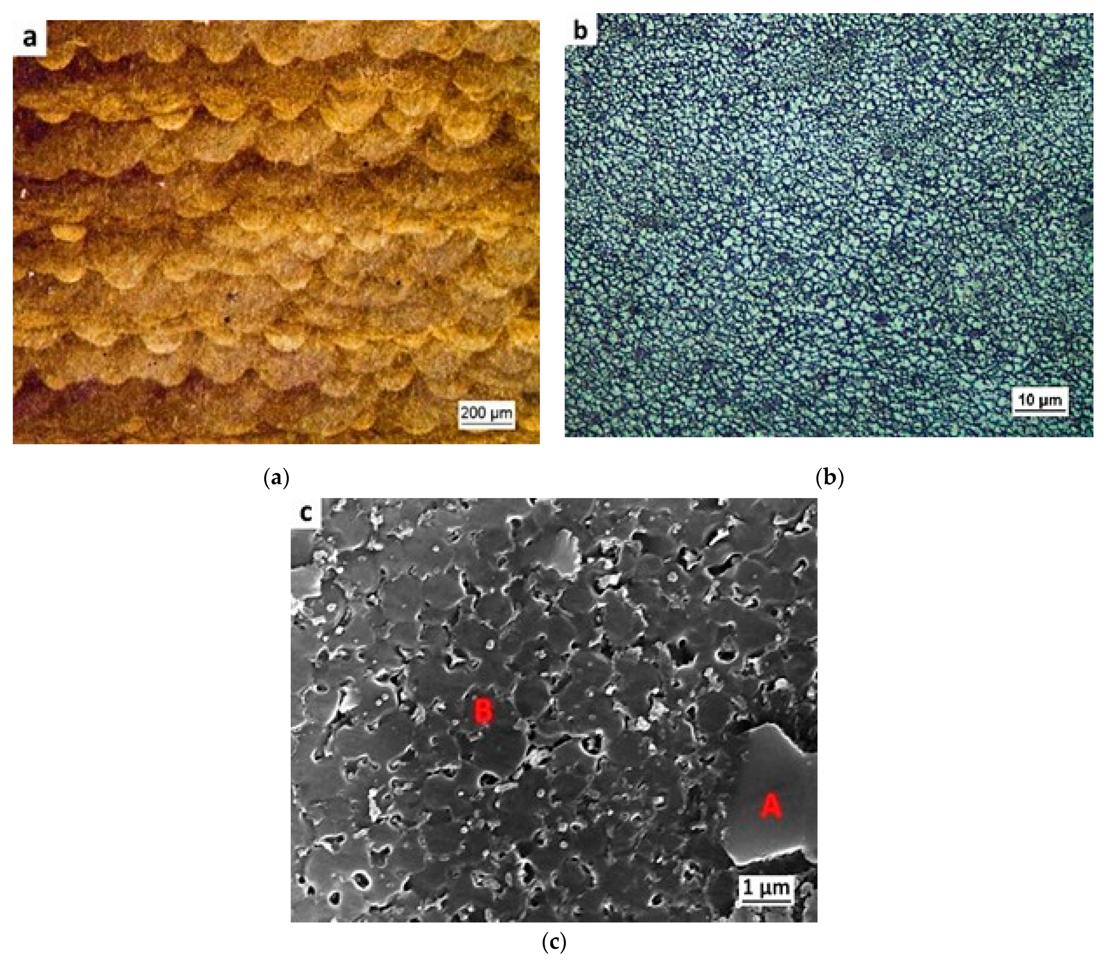
Prismatic specimens were produced by L-PBF using the pre-alloyed powder with chemical composition reported in Table 1. Figure 2a shows a low magnification optical micrograph of a section parallel to the building direction of the as-built material after chemical etching. The fish-scale pattern generated by aligned solidified melt pools is noticeable. A LOM image of the as-built material taken at higher magnification is shown in Figure 2b. It reveals a fine microstructure, characterised by micro-sized equiaxed grains. The SEM micrograph depicted in Figure 2c shows the solidification structure of the as-built material with fine α-Al cells, coarse second-phase particles (size in the order of a few micrometers) and finer particles. The finer particles are located both at boundaries and at core regions of the solidification cells.
The results of EDS chemical analysis (Table 3), which was performed on spots labelled as A and B in the micrograph of Figure 2c, reveal that the coarse particles have higher content of Ti and B than the Al cells.
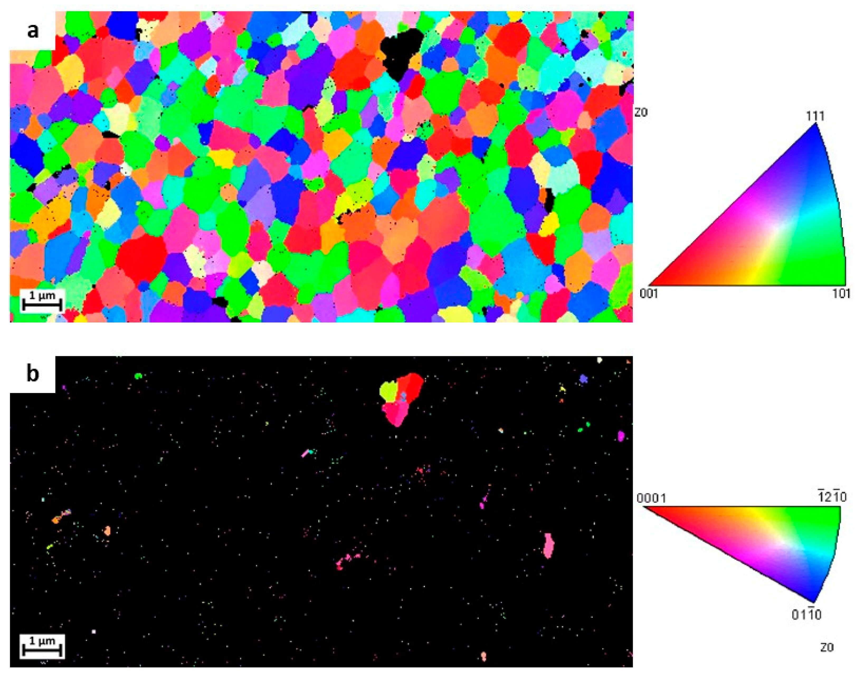
EBSD analysis was performed on the section parallel to the building direction of as-built specimens. Orientation maps of α-Al and TiB2 phases are depicted in Figure 3a,b, respectively. Fine equiaxed grains with size in the order of 1 µm are visible within the as-built microstructure, suggesting a different crystallographic orientation of each solidification cell. TiB2 particles are noticeable both within grains and along grain boundaries. Furthermore, coarser TiB2 particles were detected.
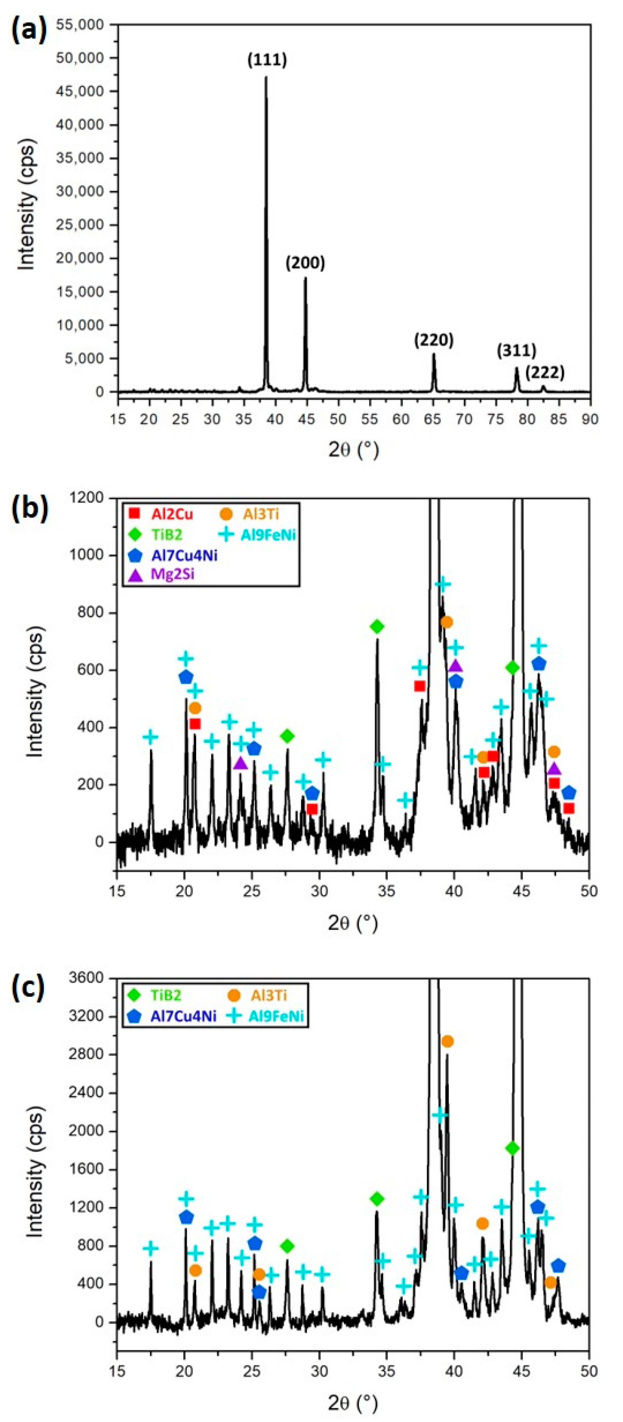
The XRD diffractograms of the as-built and ST+WQ (solution treatment + water quenching) Ti-B modified 2618 alloys are reported in Figure 4. In Figure 4a, the full diffractogram of the as-built sample is shown together with the Miller indexes of the main reflections of Al. A magnification of the background signal in the low angle 2θ region of the as-built and solution treated alloy is shown in Figure 4b,c. The results show the high intensity of Al peaks with respect to those of the second phases. A high number of peaks are noticeable at low angles, both for the as-built and solution treated samples. The characteristic peaks of TiB2, Al7Cu4Ni, Al3Ti and Al9FeNi compounds were detected in both alloy conditions. Reflections of θ-Al2Cu and β-Mg2Si phases were only identified in the diffractogram of the as-built sample. As expected, the solution treatment performed at 530 °C was able to dissolve θ and β phases [12].

3.3. Aging Response

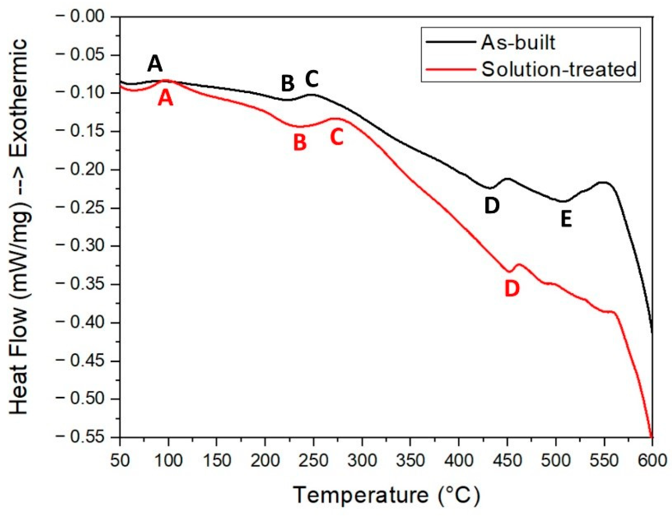
DSC curves of as-built and ST+WQ samples are reported in Figure 5 and the peak temperatures are summarised in Table 4.
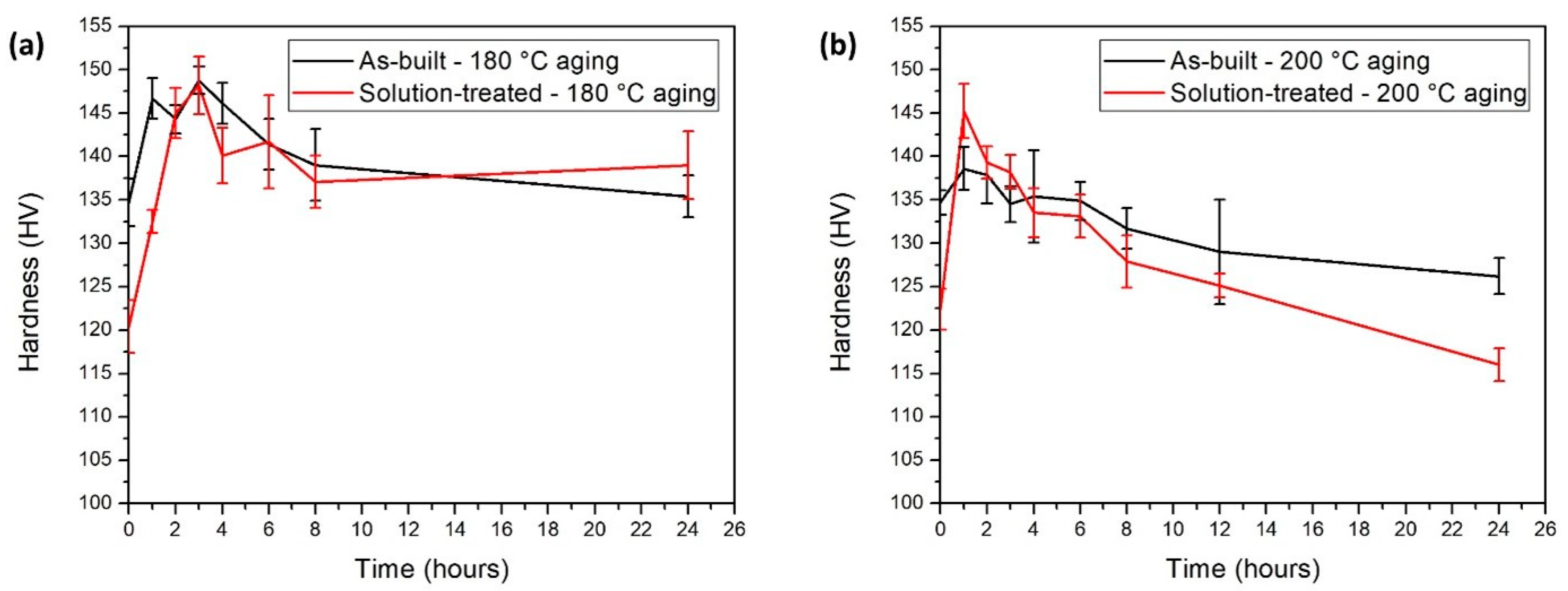
Aging response of the alloy was investigated starting from both the as-built and ST+WQ conditions. Figure 6a,b shows the material hardness as a function of the aging time at 180 and 200 °C, i.e., the temperature suggested by the ASTM standard for the EN AW 2618 alloy [11]. The solution annealing followed by water quenching causes a drop in material hardness. Indeed, as-built and solution treated specimens are characterised by micro-hardness values of 135 HV and 120 HV, respectively. The highest hardness value (148.8 HV) was achieved by aging the as-built material at 180 °C for 3 h. The aging curves at 200 °C are shifted toward lower times as compared to those at 180 °C, due to accelerated precipitation kinetics. As expected, the over-ageing phenomenon is more pronounced when the heat treatment is carried out at 200 °C. It is worth noting that, even after an exposure time of 24 h at 180 °C, the material hardness keeps stable at around 135 HV.
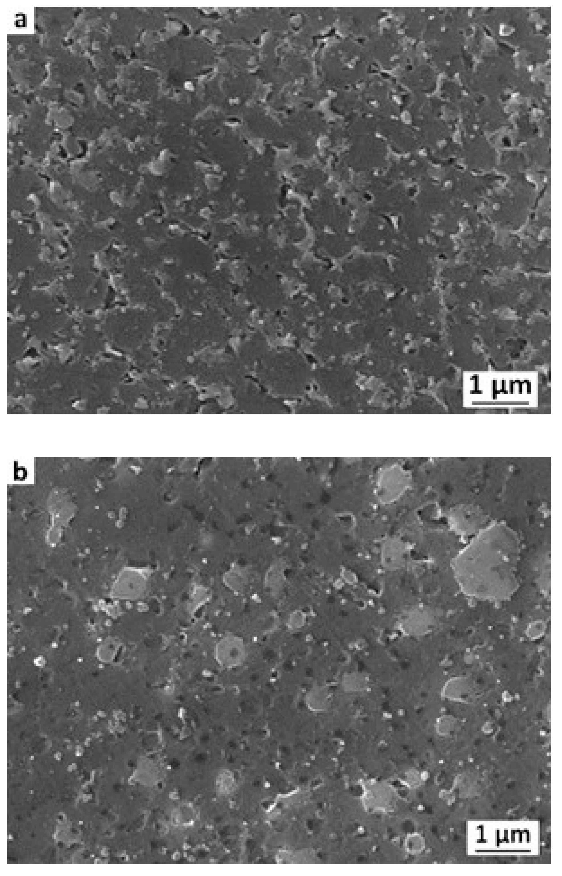
SE-SEM analysis was performed on specimens aged at 180 °C for 3 h corresponding to peak-hardness aging, both starting from the as-built and solution treated conditions, namely the T5 and T6 tempers, respectively (Figure 7). In the T5-treated alloy, the solidification structure with second phases at cell boundaries and within the cell cores is still visible. On the contrary, solution annealing led to a radical change in microstructure. Indeed, solidification cells are no longer noticeable in the T6-treated alloy and second-phase particles significantly coarsen.

3.4. Mechanical Properties

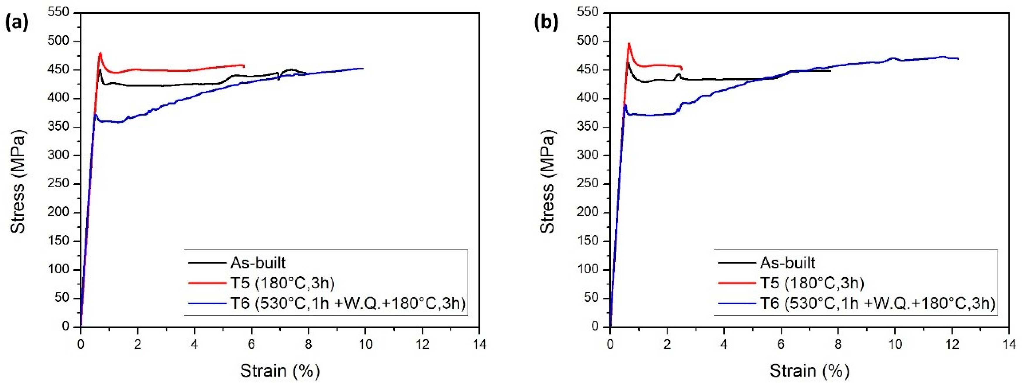
Tensile tests were carried out at room temperature on as-built, T5- and T6-treated dogbone specimens with longitudinal axis parallel and orthogonal to the building direction, which were named as Z- and XY-specimens, respectively. Representative tensile curves are shown in Figure 8 and upper yield strength (UYS), ultimate tensile strength (UTS) and elongation at fracture values are reported in Table 5. The curves are characterised by a lower and an upper yield strength, especially pronounced in the as-built and T5 specimen records. Significative strain-hardening was noticeable only in the tensile curve of T6 specimens. The alloy in the T5 condition revealed the highest UYS, reaching 495.6 MPa and 478.5 MPa for the XY- and Z-specimens, respectively. The T6-treated alloy showed the highest elongation at fracture with respect to the other conditions.
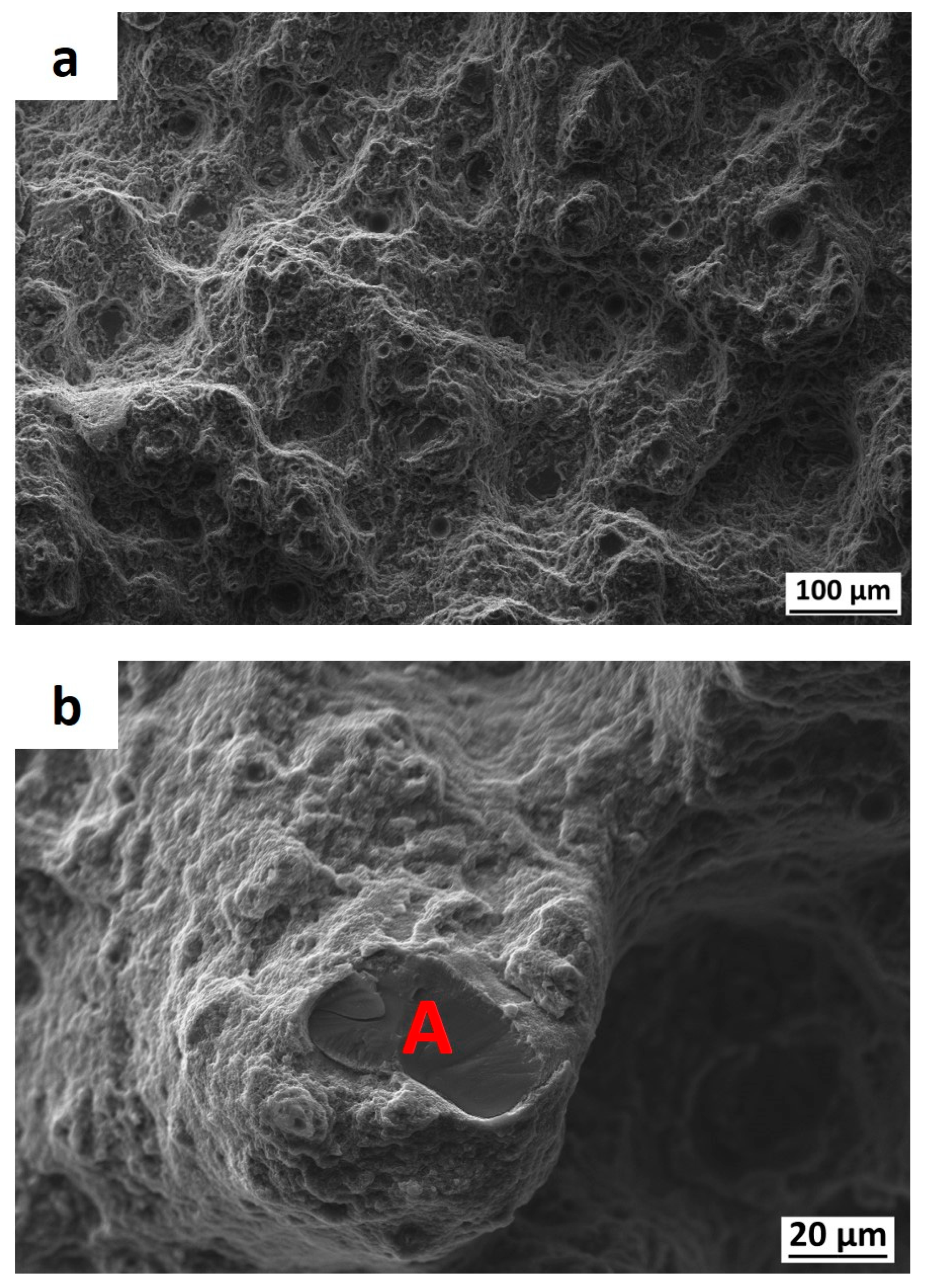
Fractographic analysis was carried out on as-built tensile samples with longitudinal axis parallel to the building direction (Z-direction). Figure 9 shows the FE-SEM images of the fracture surface of a specimen. Small dimples are noticeable on the surface fracture (Figure 9a), indicating a ductile behaviour of the material. High-magnification micrograph reveals cleavage-fracture of second phase particles (Figure 9b). EDS analysis was performed on the spot labelled as A in the micrograph of Figure 9b and a high content of Ti and B was recorded, thus the particle is likely TiB2.
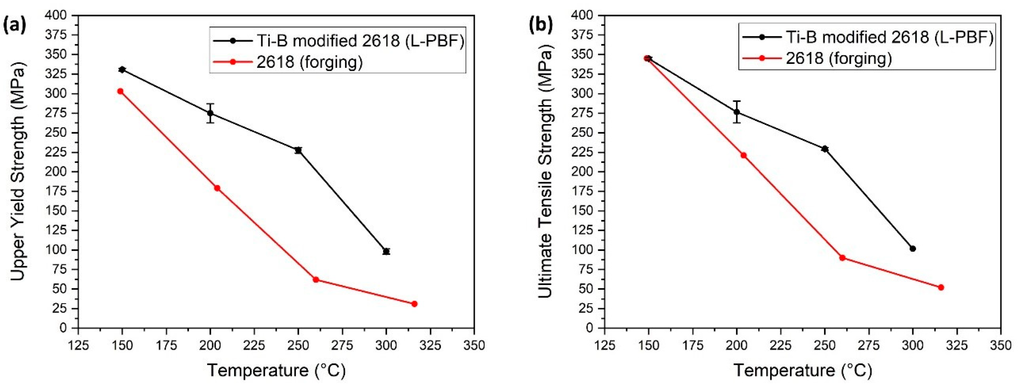
Z-specimens were also tested in the T7 condition (ST + WQ +20 h, 200 °C) at 150, 200, 250 and 300 °C. Tensile properties of the material at high temperature are summarized in Table 6. A strong drop in yield and tensile strength was noticed above 250 °C.

4. Discussion

The EN AW 2618 Al alloy is considered as a material with low L-PBF processability and highly susceptible to solidification cracking [2]. During solidification of melt pools, thermal shrinkage can promote accumulation of tensile stresses between adjacent grains. This phenomenon can lead to nucleation and subsequent propagation of hot cracks along grain boundaries. Coarse columnar grains are more susceptible to hot cracking than small equiaxed grains since they provide straight paths for cracks and also promote a larger concentration of solutes due to lower grain boundary surface area compared to equiaxed grains [5]. This work confirmed that the modification of the 2618 with Ti and B leads to a fine crack-free equiaxed grain structure, which is much more refined than that typically found in 2618 alloy processed by L-PBF [2].
The solidification curves based on Scheil equation reported in Figure 1 demonstrate that TiB2 and Al3Ti precipitate from the liquid phase. These primary phases are believed to be able to stimulate heterogeneous nucleation of α-Al grains, leading to a refined microstructure, as shown by the micrograph of Figure 2b and by the EBSD orientation map of Figure 3a. The XRD diffractograms (Figure 4) and the EBSD orientation map (Figure 3b) confirm the existence of the TiB2 phase in the as-built material.
As-built and solution treated samples showed rather similar DSC curves (Figure 5). The exothermic peak A and the endothermic peak B are likely associated to precipitation and dissolution of GP zones, respectively, whereas the exothermic peak C and the endothermic peak D are due to the formation and dissolution of S’/S precipitates, respectively, as for the conventional 2618 alloy [13,14]. At temperatures higher than 470 °C, the as-built and solution annealed samples behave differently. In particular, the alloy in the as-built condition shows a large endothermic peak E. This peak is believed to be related to the dissolution of Mg2Si (β) and Al2Cu (θ) phases, in agreement with the results of XRD analyses (Figure 4). Indeed, the solution treatment radically changes the microstructure, leading to the dissolution of the inter-cellular segregation network (Figure 7), where β and θ generate at the end of solidification (Figure 1) [12].
SEM analysis showed that the as-built alloy is characterised by fine cells, typical of rapidly solidified materials, that are surrounded by zones with pronounced solute segregation (Figure 2c). The direct aging performed from the as-built condition does not modify the morphology of second phases formed on solidification (Figure 7a). On the contrary, solution treatment leads to a drastic change in microstructure as shown by the SEM image of the T6 alloy reported in Figure 7b. The solute-rich inter-cellular network made by fine second phases is indeed replaced by coarser grains and particles. These latter identified as TiB2, Al3Ti, Al7Cu4Ni and Al9FeNi by XRD analysis (Figure 4c).
The high cooling rates produced by L-PBF process promote the formation of a supersaturated solid solution in the as-built material [7]. Thus, the material can be directly aged from the as-built condition, as confirmed from data given in Figure 5 and Figure 6. The solution treatment causes a decrease in material hardness, likely due to microstructural coarsening and reduction of the dislocation density. Both as-built and solution treated alloys reached the maximum hardness after 1 h and 3 h at 200 °C and 180 °C, respectively. Additionally, aging curves shown in Figure 6 highlight the faster precipitation kinetics of the novel alloy with respect to a conventional wrought EN AW 2618, which exhibits, according to literature, the hardness peak after 20 h of exposure at 200 °C [15].
Results of tensile tests show that the T6 alloy modified with Ti and B shows values of UYS and UTS similar to those attained in wrought 2618 alloy in T6 temper. Indeed, R. Nunes et al. reported a UYS and UTS of 372 and 440 MPa, respectively, for the conventional T6-2618 alloy processed by forging [16]. Figure 8 and Table 5 show UYS values of 461, 495 and 392 MPa and UTS values of 447, 460 and 470 MPa for the for the as-built, T5 and T6 XY-specimens, respectively. The high solidification and cooling rates generated by L-PBF are supposed to be responsible for the formation of extended solid solution and the refined microstructure in the as-built material, resulting in high strength already after solidification and cooling. The T5 treated alloy showed higher strength values with respect to the as-built material, due to the capability of the alloy to respond to direct aging. The T6 treated alloy, which is characterised by coarser microstructure, showed higher elongation at fracture but lower UYS as compared to the T5 and as-built conditions. As shown by the results of tensile tests performed along the Z- and XY-directions, the alloy exhibits an almost-isotropic behaviour [4]. The epitaxial and competitive growth of coarse columnar grains is indeed suppressed by heterogeneous nucleation of grains stimulated by the addition of nucleants.
Finally, it is to consider that the alloy with Ti and B printed by L-PBF shows higher mechanical strength at elevated temperatures with respect to the conventional 2618 alloy produced by forging. Figure 10 shows the UYS vs. temperature (a) and UTS vs. temperature (b) plots of conventional wrought T6-treated 2618 [16] and T7-treated Ti-B modified 2618 alloy of the present study.
It can be supposed that TiB2 and Al3Ti particles stabilise the microstructure and enhance the mechanical behaviour of the Ti-B modified 2618 alloy at high temperatures. Although the elongation at fracture of the novel alloy at high temperatures shows lower values with respect to that of the conventional 2618 alloy, their absolute values are considered as appreciable for structural applications, ranging between 14.3% and 22.0%.

5. Conclusions

Based on experimental and simulation results, the following conclusions can be drawn:
  • The addition of titanium and boron positively affects the processability of the 2618 Al alloy produced by L-PBF process. TiB2 and Al3Ti particles promote the formation of an equiaxed microstructure and the suppression of the solidification cracking phenomenon.
  • Solidification and cooling rates induced by L-PBF processing are fast enough to generate supersaturated solid solutions with aging potential, as shown by DSC and aging curves.
  • Solution treatment modifies the microstructure of the material, leading to the dissolution of micro-segregation at cell boundaries and to the formation of coarser particles.
  • At room temperature, as-built XY-specimens show UYS and UTS of 461 MPa and 447 MPa, respectively. The T5 samples achieve UYS and UTS of 495 MPa and 460 MPa and, after T6 temper, of 392 MPa and 470 MPa, respectively.
  • At high temperature, the Ti-B modified 2618 alloy printed by L-PBF process shows higher mechanical properties with respect to the conventional alloy produced by forging.

Author Contributions

Conceptualization, M.V., R.C., and F.B.; data curation, F.B.; formal analysis, F.B. and R.C.; funding acquisition, M.V. and R.C.; investigation, F.B. and M.Y.K.; methodology, F.B. and R.C.; project administration, M.R., R.C, M.V.; resources: R.C., M.V. and M.R.; software, M.Y.K.; supervision, R.C. and A.R.; writing—original draft preparation, F.B.; writing—review & editing, M.V., R.C. and F.B. All authors have read and agreed to the published version of the manuscript.

Funding

The present research was partially funded by the EIT Raw Materials project SAMOA (Sustainable Aluminium Additive Manufacturing for high-performance applications). The Italian Ministry of Education, University and Research is acknowledged for the support provided through the Project “Department of Excellence LIS4.0 – Lightweight and Smart Structures for Industry 4.0”.

Data Availability Statement

The data presented in this study are available on request from the corresponding author.

Conflicts of Interest

The authors declare no conflict of interest.

References

  1. Yap, C.Y.; Chua, C.K.; Dong, Z.L.; Liu, Z.Z.; Yhang, D.Q.; Loh, L.E.; Sing, S.L. Review of selective laser melting: Materials and applications. Appl. Phys. Rev. 2015, 2, 041101. [Google Scholar] [CrossRef]
  2. Koutny, D.; Palousek, D.; Pantelejev, L.; Hoeller, C.; Pinchler, R.; Tesicky, L.; Kaiser, J. Influence of scanning strategies on processing of aluminum alloy EN AW 2618 using selective laser melting. Materials 2018, 11, 298. [Google Scholar] [CrossRef] [PubMed] [Green Version]
  3. Uddin, S.Z.; Espalin, D.; Mireles, J.; Morton, P.; Terrazas, C.; Collins, S.; Murr, L.E.; Wicker, R. Laser powder bed fusion fabrication and characterization of crack-free aluminum alloy 6061 using in-process powder bed induction heating. In Proceedings of the 28th Annual International Solid Freeform Fabrication Symposium—An Additive Manufacturing Conference, Austin, TX, USA, 7–9 August 2017; pp. 214–227. [Google Scholar]
  4. Montero-Sistiaga, M.L.; Martens, R.; Vrancken, B.; Wang, X.; Van Hooreweder, B.; Kruth, J.-P.; Van Humbeeck, J. Changing the alloy composition of Al7075 for better processability by selective laser melting. J. Mater. Process. Technol. 2016, 238, 437–445. [Google Scholar] [CrossRef]
  5. Kou, S. Solidification and liquation cracking issues in welding. JOM 2003, 55, 37–42. [Google Scholar] [CrossRef]
  6. Martin, J.H.; Yahata, B.D.; Hundley, J.M.; Mayer, J.A.; Schaedler, T.A.; Pollock, T.M. 3D printing of high-strength aluminium alloys. Nature 2017, 549, 365–369. [Google Scholar] [CrossRef] [PubMed]
  7. Casati, R.; Coduri, M.; Riccio, M.; Rizzi, A.; Vedani, M. Development of a high strength Al-Zn-Si-Mg-Cu alloy for selective laser melting. J. Alloys Compd. 2018, 801, 243–253. [Google Scholar] [CrossRef]
  8. Zhang, H.; Zhu, H.; Nie, X.; Yin, J.; Hu, Z.; Zeng, X. Effect of Zirconium addition on crack, microstructure and mechanical behavior of selective laser melted Al-Cu-Mg alloy. Scr. Mater. 2017, 134, 6–10. [Google Scholar] [CrossRef]
  9. Wang, P.; Gammer, C.; Brenne, F.; Niendorf, T.; Eckert, J.; Scudino, S. A heat treatable TiB2/Al-3.5 Cu-1.5 Mg-1Si composite fabricated by selective laser melting: Microstructure, heat treatment and mechanical properties. Compos. Part B Eng. 2018, 147, 162–168. [Google Scholar] [CrossRef]
  10. ASTM Committee on Mechanical Testing. Standard Test Methods for Tension Testing of Metallic Materials; ASTM International: West Conshohocken, PA, USA, 2013; pp. 1–28. [Google Scholar]
  11. ASTM International. Experiment: Heat Treatment—Quenching & Tempering. Mater. Sci. Eng. 2016, 31. [Google Scholar] [CrossRef]
  12. Elgallad, E.M.; Shen, P.; Zhang, Z.; Chen, X.-G. Effects of heat treatment on the microstructure and mechanical properties of AA2618 DC cast alloy. Mater. Des. 2014, 61, 133–140. [Google Scholar] [CrossRef]
  13. Casati, R.; Lemke, J.N.; Alarcon, A.Z.; Vedani, M. Aging Behavior of High-Strength Al Alloy 2618 Produced by Selective Laser Melting. Metall. Mater. Trans. A Phys. Metall. Mater. Sci. 2017, 48, 575–579. [Google Scholar] [CrossRef]
  14. Lecis, N.; Fiocchi, J.; Vedani, M.; Bonollo, F.; Fabrizi, A.; Casati, R. Effect of ball milling on the ageing response of Al2618 composites reinforced with SiC and oxide nanoparticles. J. Alloys Compd. 2016, 693, 909–920. [Google Scholar] [CrossRef]
  15. Ceschini, L.; Morri, A.; Morri, A.; Di Sabatino, M. Effect of thermal exposure on the residual hardness and tensile properties of the EN AW-2618A piston alloy. Mater. Sci. Eng. A 2015, 639, 288–297. [Google Scholar] [CrossRef]
  16. Nunes, R.; Adams, J.H.; Ammons, M.; Avery, H.S. Properties and Selection: Non-ferrous Alloys and Special-Purpose Materials; ASM International: Almere, The Netherlands, 1998; Volume 157. [Google Scholar] [CrossRef]
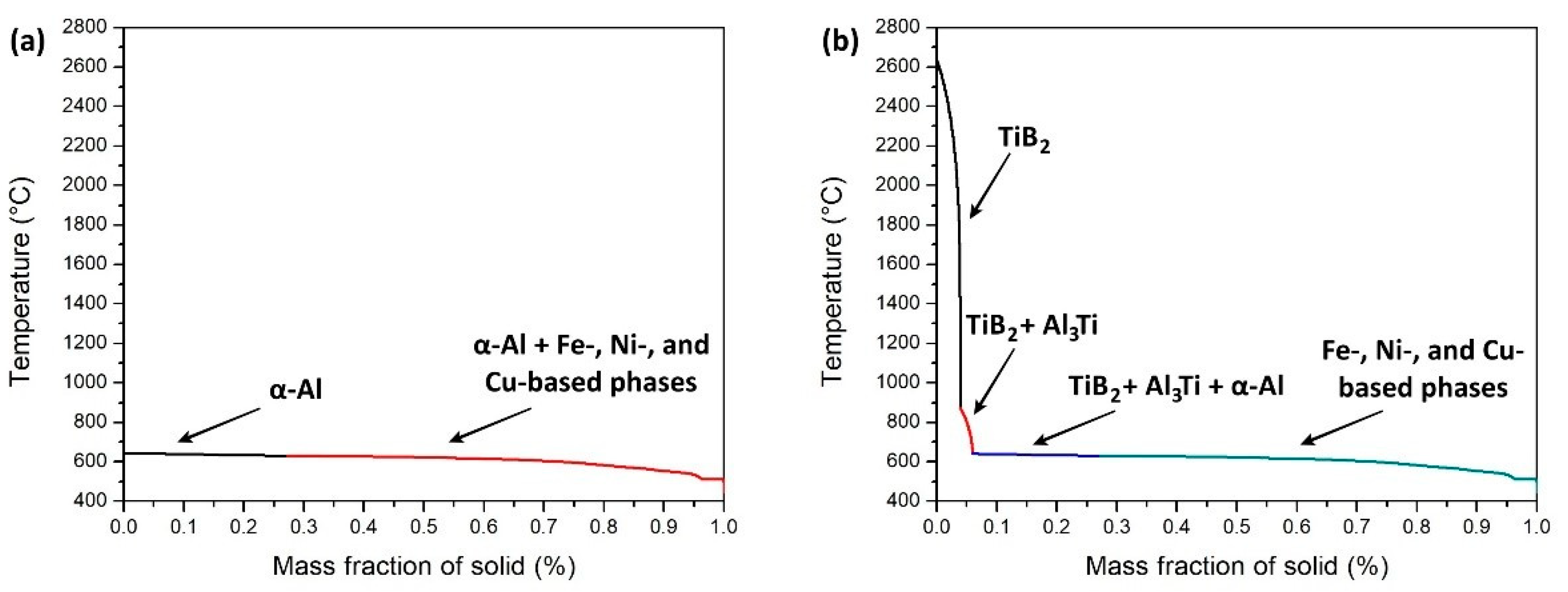
Figure 1. Solidification curves of (a) 2618 and (b) Ti/B-2618 alloys.
Metals 11 00035 g001
Figure 2. (a) Low magnification LOM image, (b) high magnification LOM image and (c) SE-SEM micrographs of the section parallel to the building direction of the as-built alloy etched in Keller’s solution.
Metals 11 00035 g002
Figure 3. EBSD orientation maps of (a) α-Al and (b) TiB2 phases.
Metals 11 00035 g003
Figure 4. (a) XRD diffrattograms of the as-built alloy; background signal in the low angle 2θ region of the (b) as-built and (c) solution treated alloys.
Metals 11 00035 g004
Figure 5. DSC curves of as-built and solution treated samples.
Metals 11 00035 g005
Figure 6. Aging curves of as-built and solution treated samples performed at (a) 180 °C and (b) 200 °C.
Metals 11 00035 g006
Figure 7. SE-SEM images of artificially-aged (a) as-built and (b) solution treated samples after Keller’s etching.
Metals 11 00035 g007
Figure 8. Room-temperature tensile curves of the as-built, T5 and T6 (a) Z- and (b) XY-specimens.
Metals 11 00035 g008
Figure 9. (a) Low- and (b) high-magnification FE-SEM micrographs performed on the surface of fracture of as-built tensile samples with longitudinal axis parallel to the building direction (Z-direction).
Metals 11 00035 g009
Figure 10. (a) UYS vs. Temperature and (b) UTS vs. Temperature plots of conventional and Ti-B modified 2618 alloys [16].
Metals 11 00035 g010
Table 1. Chemical composition (wt.%) of the pre-alloyed 2618 Al alloy modified with Ti and B.
TiBCuMgFeNiSiAl
3.51.22.31.60.81.10.3Bal.
Table 2. Optimal combination of process parameters.
Layer Thickness [mm]Platform Temperature [°C]Hatch Distance [mm]Laser Power [W]Scanning Speed [mm/s]Volumetric Energy Density [J/mm3]
0.050600.11325100059.09
Table 3. EDS analysis of the spots labelled as A and B in the micrograph of Figure 2c.
SpotsTiBCuMgFeNiSi
Spot A (wt.%)11.625.01.71.00.60.80.3
Spot B (wt.%)4.5-2.71.11.01.4-
Table 4. Peak temperatures (°C) attained from the DSC curves of as-built and solution treated samples.
PeaksAs-BuiltSolution Treated
Peak A84.196.8
Peak B221.2235.4
Peak C248.2272.0
Peak D431.5452.2
Peak E507.6-
Table 5. Room-temperature mechanical properties of the as-built, T5 and T6 Ti/B-2618 alloys.
SamplesUpper Yield Strength [MPa]Tensile Strength [MPa]Elongation at Fracture [%]
XY–as-built461.2 (±0.9)447.8 (±0.9)7.3 (±0.5)
Z-as-built447.7 (±2.6)448.3 (±2.2)7.2 (±0.2)
XY-T5495.6 (±0.5)460.5 (±1.3)2.5 (±0.4)
Z-T5478.5 (±0.9)460.2 (±1.6)6.1 (±0.9)
XY-T6392.1 (±6.3)470.7 (±7.9)10.5 (±1.0)
Z-T6375.1 (±9.3)453.8 (±3.9)8.8 (±1.1)
Table 6. High temperature mechanical properties of T7-treated Ti/B-2618 Al alloy.
Temperature [°C]Upper Yield Strength [MPa]Tensile Strength [MPa]Elongation at Fracture [%]
150330.7 (±1.7)344.8 (±1.8)12.5 (±1.0)
200274.8 (±12.2)276.5 (±14.0)19.3 (±0.3)
250227.5 (±3.5)229.3 (±1.8)14.2 (±2.2)
30098.0 (±3.5)101.5 (±0.0)22.0 (±1.0)
Publisher’s Note: MDPI stays neutral with regard to jurisdictional claims in published maps and institutional affiliations.