Article

Optimization of the Post-Process Heat Treatment of Inconel 718 Superalloy Fabricated by Laser Powder Bed Fusion Process

1
Department of Mechanical, Industrial and Aerospace Engineering, Concordia University, 1515 Rue Sainte Catherine West, Montreal, QC H3G 2W1, Canada
2
Department of Mechanical Engineering, École de Technologie Supérieure, 1100, Notre-Dame Street West, Montreal, QC H3C 1K3, Canada
*
Author to whom correspondence should be addressed.
Metals 2021, 11(1), 144; https://doi.org/10.3390/met11010144
Submission received: 9 December 2020 / Revised: 7 January 2021 / Accepted: 8 January 2021 / Published: 12 January 2021
(This article belongs to the Section Additive Manufacturing)

Abstract

:
In the present study, multi-objective optimization is employed to develop the optimum heat treatments that can achieve both high-mechanical performance and non-distinctive crystallographic texture of 3D printed Inconel 718 (IN718) fabricated by laser powder bed fusion (LPBF). Heat treatments including homogenization at different soaking times (2, 2.5, 3, 3.5 and 4 h) at 1080 °C, followed by a 1 h solution treatment at 980 °C and the standard aging have been employed. 2.5 h is found to be the homogenization treatment threshold after which there is a depletion of hardening precipitate constituents (Nb and Ti) from the γ-matrix. However, a significant number of columnar grains with a high fraction (37.8%) of low-angle grain boundaries (LAGBs) have still been retained after the 2.5 h homogenization treatment. After a 4 h homogenization treatment, a fully recrystallized IN718 with a high fraction of annealing twins (87.1%) is obtained. 2.5 and 4 h homogenization treatments result in tensile properties exceeding those of the wrought IN718 at both RT and 650 °C. However, considering the texture requirements, it is found that the 4 h homogenization treatment offers the optimum treatment, which can be used to produce IN718 components offering a balanced combination of high mechanical properties and adequate microstructural isotropy.

Graphical Abstract

1. Introduction

Inconel 718 (IN718) is the most widely nickel-based superalloy used in different industrial spheres such as the petrochemical, aeronautics, energy, and aerospace sectors [1,2]. Thanks to its outstanding combination of superior strength, high creep performance, and high resistance to wear, oxidation and corrosion, even at cryogenic and elevated temperatures (up to 650 °C), IN718 is a suitable candidate for numerous applications. It is typically used in critical components subjected to aggressive environments in jet and gas turbine engines, nuclear plants and cryogenic tanks, which are produced using conventional manufacturing processes such as forging and casting [2]. However, as components are becoming ever more complex and advancements in engine performance accelerate, attention is shifting from the traditional material processing technologies to additive manufacturing (AM) processes [3,4]. For instance, approximately 100,000 parts were anticipated to be produced using the AM technology by General Electric aviation by 2020 [5]. Among AM techniques, the laser powder bed fusion (LPBF) process has gained the most attention due to its ability to customize IN718 components with high density and mechanical properties comparable to those of wrought alloy after appropriate heat treatments. Nevertheless, the widespread use and implementation of this technique in some specific applications, that demand isotropic mechanical properties, are only just beginning due to the vertically <100> aligned columnar microstructure of the as-printed LPBF IN718 alloy, in addition to other manufacturing drawbacks [6,7].
Directional solidification, as a well-known phenomenon in as-printed IN718 and in other engineering materials fabricated using the LPBF process, occurs as a result of directional heat transfer along the building direction during the printing process: the heat transfers from the upper surface of the powder bed, where the laser beam is focused, toward the building platform [8]. Such a significant uniaxial thermal gradient culminates in the production of materials characterized by a strong texture, and consequently, anisotropic properties. In addition, other difficulties prevented obtaining consistent mechanical properties from different LPBF machines due to the high dependence of the properties on the part orientation during printing, as well as on the laser scanning strategy adopted [9]. It is realized that the columnar grain morphology with strong fiber texture leads to improving the creep resistance for some specific applications such as turbine blades and turbine disks [10]. However, numerous other applications are demanding microstructure with fine equiaxed grains to improve the material strength, fatigue properties and intergranular crack propagation resistance as well as producing components with isotropic properties [11,12]. Hence, several in-situ solutions have been introduced to control and mitigate the thermal gradient, such as pre-heating of the building chamber and the application of the laser rescanning strategy. Furthermore, customization of the laser process parameters, such as laser beam intensity profile (beam shape) and scanning strategy, is performed to control solidification, and thus grain structure and texture, depending on the fact that the grain structure is strongly governed by the variation of the ratio of thermal gradient (G) along the building direction and the solidification growth rate (R) [11,13].
For instance, Shi et al. [11] and Rongpei et al. [13], investigated the impact of different laser beam profiles, circular Gaussian (CG), longitudinal elliptical (LE) and transverse elliptical (TE), on the microstructure of a single track of LPBF-fabricated 316 L stainless steel. Their [11,13] results show that the elliptical laser profile, in general, had a significant impact on the solidification microstructure that allowed the freedom to tailor the grain morphology and material texture. For comparison, the use of the TE laser profile resulted in wider, shorter and shallower melt pool dimensions along the transverse, scanning and building direction, respectively, when compared to CG and TE ones. Thus, a lower thermal gradient across the melting pool after TE laser scanning was obtained when compared to the CG and LE laser profiles that significantly reduced the G/R ratio and resulted in equiaxed grain morphology. However, the columnar grain structure was not completely prevented especially at the start of the scanned track [11].
As discussed, microstructure with complete equiaxed grain morphology and random texture via the manipulating of the printing process parameters has not been achieved yet. Most importantly, violating the optimized process parameters of IN718, via changing the scanning strategy and laser beam intensity, might end up with other manufacturing defects such as pores, lack of fusion, poor substrate wetting as reported by [13]. Besides, the intrinsic <100> preferred crystallographic orientation of the face-centered cubic (FCC) IN718 superalloy [8,14] is not likely to be overcome through changing the printing process parameters. Therefore, to secure consistent properties in components produced using different AM machines with different scanning strategies and to obtain isotropic mechanical properties comparable to those of wrought IN718, recrystallization is required to refine the components’ as-printed microstructure and eliminate their columnar morphology [9]. Ultimately, the use of post-LPBF heat treatments would be required to eliminate the as-printed texture of LPBF IN718 parts and improve their mechanical properties.
Most of the literature on thermal post-processing of LPBF IN718 examines different treatment regimes aiming to optimize the microstructure and mechanical properties of the alloy. However, most of the concerns they address are directed towards the evolution of precipitates and how to dissolve the detrimental phases resulting from the LPBF process. Only limited attention has been paid to the evolution of the grain structure and of the material texture during heat treatments, which are also crucial to improving the mechanical properties of LPBF IN718. Chlebus et al. [15], for instance, investigated the influence of different heat treatments, including homogenization at 1100 °C for 1 h, followed by aging treatment, on the microstructure and mechanical properties of LPBF IN718 samples printed at different orientations (0°, 45° and 90°) with respect to the building direction [15]. From their results [15], the heat-treated samples exhibited higher mechanical strengths (1320 ± 6, 1371 ± 5 and 1377 ± 66 MPa, respectively) in all directions, as compared to that of the wrought IN718 alloy (1317 MPa). However, the treatment conditions applied did not significantly change the shape of as-printed elongated grains and their crystallographic orientations, which consequently resulted in such variations in the mechanical properties between the 0°, 45° and 90° printed samples [15]. Similarly, Vilaro et al. [16] reported that significantly anisotropic mechanical properties were obtained even after the application of standard treatment conditions for nickel-based superalloys. It has been extensively reported that the standard heat treatments developed for cast (AMS5383) and wrought (AMS5662) IN718 do not eliminate the textured and columnar microstructure of the LPBF IN718 alloy [9,15,16,17,18]. Therefore, modified homogenization and solution heat treatments are required to obtain AM components with the same isotropic mechanical and homogeneous microstructures as those made from the wrought alloy.
Aside from the standard heat treatment, Diepold et al. [19] investigated the effect of different modified heat treatments—SHT930, SHT954 and SHT1000—on the microstructure and mechanical properties aiming to optimize the post-heat treatments of the LPBF-fabricated IN718. They [19] reported that the SHT1000 achieved the optimum strength due to the higher volume fraction of γ′ and γ′′ phases with no precipitation of δ-phase, as compared with those of SHT930 and SHT954 treatments. However, the as-printed texture and grain morphology did not change even after SHT930, SHT954 and SHT1000 treatments due to the lower heat treatments temperature than the recrystallization temperature [19]. Similarly, Huang, et al. [10] studied the influence of different solution treatment temperatures (from 980 to 1280 °C) on the microstructure and mechanical properties of LPBF-fabricated IN718 intending to obtain the optimum solution treatment parameters. Their [10] microstructure results show that the increase of the solution temperature from 980 to 1230 °C for 1 h resulted in more dissolution of Laves phase to reach the appropriate homogenized microstructure at 1080 °C for 1 h. Furthermore, complete recrystallization was obtained just after the solution temperature of 1130 °C for 1 h [10]. However, a solution temperature above 1080 °C for 1 h resulted in a deterioration in the mechanical properties indicating the presence of conflict between obtaining high mechanical properties and fully recrystallized material [10].
In fact, obtaining isotropic mechanical properties through the transformation of the as-printed columnar grain structure into an equiaxed structure is not the only benefit provided by the material recrystallization. The development of grain boundaries during high-temperature heat treatments also has a beneficial effect on mechanical properties. Pande et al. [20] reported that the presence of annealing twin boundaries improves the RT mechanical strength of IN718 alloy. In addition, Yuan et al. [21] reported that the annealed twin boundaries act as barriers to the dislocation glide, which consequently enhances the high-temperature creep properties. It is generally acknowledged that the transformation of columnar grains into equiaxed grains occurs as a result of the recrystallization process triggered by selecting the proper post-LPBF heat treatment. To this end, Fayed et al. [22,23], established a post-LPBF heat treatment window covering a wide range of homogenization (1080 °C; 1 to 7 h) and solution (980 °C; 15 to 60 min) treatment soaking times, and studied the effects of these treatments on the microstructure and elevated-temperature (650 °C) mechanical properties of LPBF IN718 alloy. They [22,23] concluded that the homogenization soaking time significantly affects the microstructure, precipitates, crystallographic texture and mechanical properties of this alloy. Samples subjected to a 1 h homogenization treatment exhibit higher mechanical properties than those subjected to prolonged treatment times (4 h and 7 h) [22]. However, near-complete recrystallization and equiaxed grain morphologies were obtained only after the 4 h homogenization treatment [22]. It can be observed that a trade-off between an LPBF IN718 alloy with high mechanical properties and one having a fine equiaxed microstructure with non-distinct texture appears to persist for this material [22]. Therefore, in the present study, it is a logical step to obtain the heat treatment conditions that can achieve a balance between these properties.
The objective of this study is to achieve the highest possible mechanical properties, while approaching a random crystallographic texture of LPBF IN718 components, using post-LPBF heat treatments. To provide an initial understanding of the combined effect of the homogenization and solution treatment times on the grain structure, the crystallographic texture and the mechanical properties, the design of experiments (DOE) approach was first employed. Next, a multi-objective optimization procedure was applied to identify the most desirable heat treatment conditions. Finally, the effects of the proposed treatment conditions on the microstructure and mechanical behavior at RT and at 650 °C of the post-treated LPBF alloy were studied.

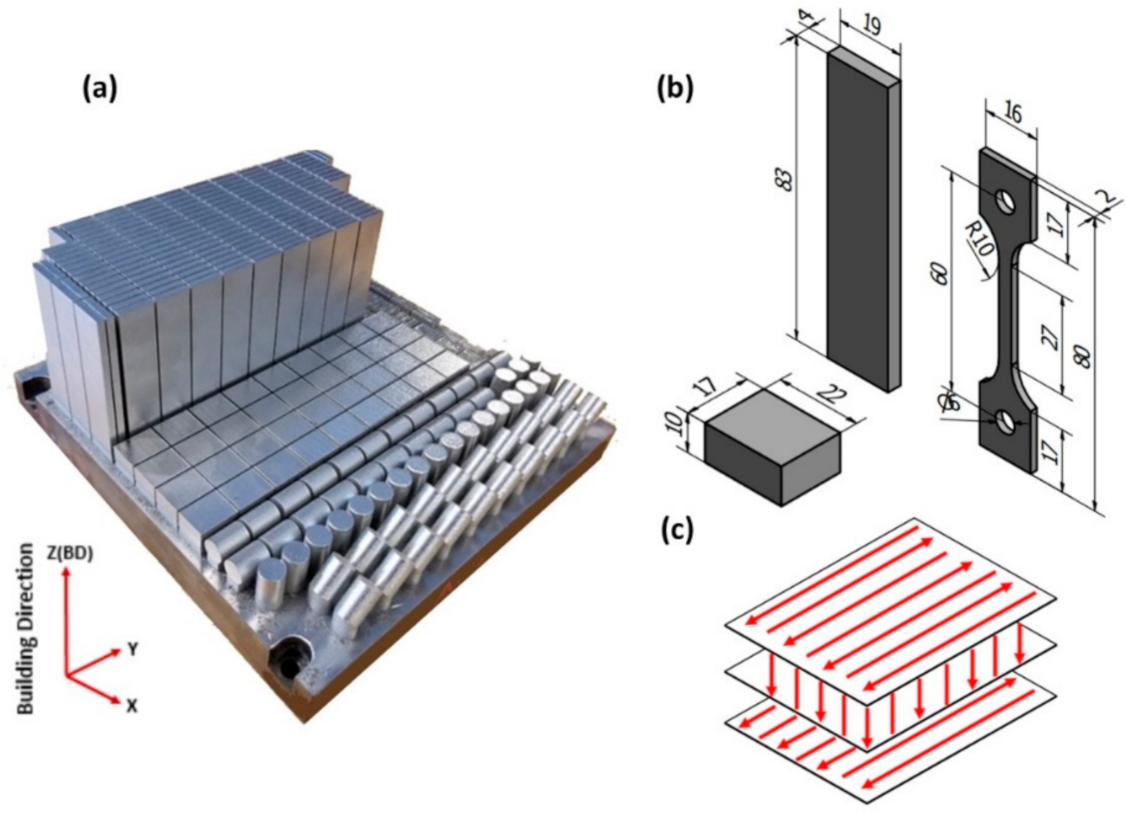
2. Materials and Methods

A gas atomized IN718 powder with a spherical shaped particles and particle size distribution of D10 (18.2 μm), D50 (32.4 μm) and D90 (54.2 μm) was used to manufacture IN718 coupons of this study. The nominal composition of the IN718 powder is listed in Table 1. An EOS M280 (EOS, Krailling, Germany) LPBF system, equipped with a fiber laser with a maximum power of 400 watts, was employed to additively manufacture the IN718 coupons using the EOS Original IN718_Surface 1.0 Parameter Set. The process parameters are listed in Table 2. In the present study, 22 × 17 × 10 mm3 cuboid coupons were fabricated for the microstructural analysis, whereas 19 × 4 × 83 mm3 rectangular prismatic coupons were manufactured for the tensile testing. Details of the scanning strategy and the printing direction of these coupons, with respect to the building direction (BD), are illustrated in Figure 1. To retain the as-printed microstructure, the IN718 coupons were extracted from the building platform using wire electric discharge machining (WEDM) just after the LPBF printing process.
To identify the optimum heat treatment conditions to be applied in the present study and to understand the effect of interaction of the homogenization and solution treatment times on the microstructure and mechanical properties, the DOE approach was employed, using the previously obtained results [22,23] and Design-Expert 12 software [24]. Details of the optimization criterion and the proposed treatment conditions are discussed in Section 3.1. The heat treatments were carried out using an electric-resistance furnace. A set of K-type thermocouples was used to monitor the samples’ temperature during the heat treatments, whereby the temperature difference was controlled within ±5 °C.
The microstructure of the as-printed and heat-treated IN718 samples was examined using a scanning electron microscope, SEM (TM3000, Hitachi, Minato, Tokyo, Japan). For the microstructural analysis, the as-printed and heat-treated IN718 samples were sectioned using a slow cutter (Buehler, Lake Bluff, IL, USA) with a mineral oil bath to prevent heat generation. The sectioned samples were hot-mounted using a conductive epoxy, and mechanically ground from 240 up to 1200 grit size using silicon carbide emery papers; they were then polished down to 1 μm using alcohol-based diamond suspension. Furthermore, the microstructure orientation and grain structure were investigated using a SEM (SU-8230, Hitachi) equipped with an e-Flash HR+ electron backscatter diffraction (EBSD) detector (Bruker, Minato, Tokyo, Japan) with 20 kV and a pixel size of 1.62 μm. An EBSD analysis was carried out on the vertical cross-sections (parallel to the building direction) only, inasmuch as the grain structure and crystallographic orientation in this plane are of main interest. To cover the maximum number of grains, the total surface area analyzed by EBSD for each condition was 1298 × 973.4 μm2. The extracted EBSD data were post-processed using ATEX [25] and QUANTAX ESPRIT software [26]. For the EBSD samples, similar aforementioned surface preparation procedures were performed, whereupon further polishing was performed using the VibroMet™ (Buehler, Lake Bluff, IL, USA) for 24 h, with a 0.05 size colloidal silica. Finally, a Hitachi IM4000 Plus ion milling system was used to remove remaining scratches with an accelerating voltage of 6 kV and a rotation speed of 25 rpm, for 40 min. For texture and phase analyses, X-ray diffraction, XRD (X’pert Pro X-ray diffractometer, PANAnalytical, Almelo, The Netherlands) with a CuKα radiation at 45 kV and 35 mA was employed. A 2θ scanning range was selected from 30° to 100° to cover the maximum possible number of diffraction peaks. For the heat-treated samples, XRD analysis was conducted prior to the aging step to monitor the effect of the soaking times of the preceding homogenization treatment on the as-printed microstructure. For consistency, all XRD patterns were acquired from the xy-plane (perpendicular to the building direction) of the as-printed and heat-treated samples.
The standard tensile properties of the as-printed and heat-treated conditions at RT and at elevated-temperature (650 °C) were determined with a strain rate of 10−3 s−1. The tensile specimens, according to the ASTM E8M standards, were machined from the as-printed rectangular coupons with the dimensions shown in Figure 1b using the WEDM. It is worth mentioning that the net shape of the tensile test samples was not directly printed due to the non-consistent and relatively poor surface finish of the as-printed parts with respect to that required for the tensile testing. All the heat treatments were performed before the WEDM, to avoid the sample distortion caused by LPBF-induced residual stresses during the machining process. The tests were performed using an MTS 810 machine (MTS Systems, Eden Prairie, MN, USA), and two to three tensile samples were tested for each condition, and their average values reported. For the elevated-temperature tensile testing, the machine was equipped with an infrared radiant heating furnace. The tensile samples were heated up to 650 °C with a heating rate of 1 °C/sec, and then held for 10 min to obtain a uniform temperature distribution along the sample. To this end, three K-type thermocouples were equally spaced along the gauge length. The central thermocouple was used to control the temperature of tensile samples during testing. To avoid the thermal expansion effect during heating, all tensile samples were preloaded with a constant force of 50 N. Furthermore, an argon shielding gas flow (4.7 L/min) was used to minimize oxidation during the elevated-temperature testing.

3. Results and Discussion

3.1. Effect of the Interaction between Homogenization and Solution Treatment Times on the Mechanical Properties and Crystallographic Texture

Based on the previously obtained experimental results [22,23], three-dimensional (3D) response surface graphs of the evolution of (a) the tensile properties of LPBF IN718 alloy at 650 °C (tensile strength (TS), yield strength (YS), elongation to failure (EL)), (b) the room temperature Vickers microhardness (HV0.5/15), and (c) the texture degree ( f ) were plotted in Figure 2 as functions of the homogenization and solution treatment times, using Design-Expert 12 software [24]. The soaking times for both the homogenization and solution treatments were defined as factors, whereas the TS, YS, El, HV and f values of the heat-treated LPBF IN718 were defined as responses. The homogenization treatment time ranged from 1 to 7 h, while for the solution treatment, it went from 15 to 60 min. Details of the heat treatment conditions and their corresponding responses, which were used to plot the response surface graphs, are listed in Table 3. The degree of the material texture in the heat-treated conditions is defined by the intensity ratio f as reported in [27,28], which can be defined as:
f = I 111 I 200 .
where I(111) and I(200) designate the diffraction peak intensity of the {111} and {200} planes, respectively, which were obtained from the XRD analysis [22]. Thus, the lower the value of ratio f, the stronger the {200} texture, whereas the larger this value, the closer it is to a non-distinct {111} texture.
Generally, as can be seen in Figure 2a–e, changes in the homogenization time at 1080 °C have a significant influence on all the responses (TS, YS, El, HV and f), regardless of the solution treatment time. The 1 h homogenization treatment resulted in the highest tensile and yield strengths, ductility and RT hardness, whereas increasing the treatment time to 4 and 7 h led to a significant reduction in the intensity of the changes, as can be seen in Figure 2a–d. Such high mechanical properties appearing after the 1 h homogenized conditions are attributable to the retention of the as-printed dislocation networks inherited from the printing process, due to the rapid and repetitive heat and cooling, as observed from the kernel average misorientation angle (KAM) analysis in [23]. Furthermore, a high release of the strengthening phase constituents (Nb and Ti) into γ-matrix after the 1 h homogenization treatments, as indicated by the remarkable expansion of lattice parameters of γ-matrix in [22], is expected to lead to more precipitation of γ′ and γ′′ phases during aging treatment as compared to the prolonged homogenization conditions, that consequently improved the mechanical properties at both RT and 650 °C. A high elongation to failure after the 1 h homogenization treatment (Figure 2e) can be attributed to the orientation of the elongated grain longitudinal axes along the tensile loading direction, because these heat treatment conditions did not significantly modify the as-printed grain structure and strong crystallographic orientation, as was previously observed in Figure 14b in [22].
For the prolonged homogenization heat treatments (4 and 7 h), reductions in the tensile strength, ductility and hardness are attributable to the significant impact of this process on the annihilation of the dislocation tangles and on the intensification of the precipitation of MC-type carbides. The latter consumes significant amounts of Nb and Ti, which are the main contributors to γ′ and γ″ phase precipitations during aging treatment, as confirmed by the lattice parameter calculations and peak shift analysis in [22].
For the solution treatment at 980 °C, it is important to note that after the 1 h homogenization treatment, the solution time had a considerable impact on the tensile and yield strengths of the LPBF IN718 alloy, as shown in Figure 2a,b. This can be attributed to a more intense needle-like δ-phase precipitation along the grain boundaries (≈0.7% area fraction) with longer solution treatments (60 min) as quantified in our previous study [23], contributing to an improvement of the grain boundary strength. During plastic deformation at high temperatures, the pinning effect of the δ-phase on the sliding of the grain boundary and impediment of the dislocation movements improves the mechanical strength of the IN718 superalloy [29]. However, after the longest homogenization treatment (7 h), the solution time had a very limited impact on the TS and YS values, as illustrated in Figure 2a,b. This is attributable to a significant impact of the 7 h homogenization treatment to eliminate the Nb-enriched regions along the grain boundaries inherited from the LPBF printing process, and distribute it more uniformly in γ-matrix [22]. Thus, the Nb concentration along the grain boundaries becomes insufficient to drive the precipitation of δ-phase, which preferentially precipitates in Nb-enriched areas (at least 6–8 wt.%) [30]. Such a decrease in the amount of δ-phase precipitates results in a smaller impact of the solution time on the mechanical properties after the 7 h homogenization treatment.
Regarding the RT microhardness after the 1 h homogenization treatment, the effect of the presence of δ-phase is the opposite of the effect of the treatment on the tensile and yield strengths, since the greater the concentration of needle-like δ-phase precipitates (≈0.7% area fraction) after solution treatment for 60 min [23], the lower the material hardness (see Figure 2d). This suggests that a greater precipitation of δ-phase (Ni3Nb) consumes more Nb at the expense of the primary strengthening phase (γ″) formation, which consequently resulted in decreasing the hardness values. In contrast, after the 7 h homogenization treatment, both solution treatment conditions (15 and 60 min) resulted in comparable RT hardness values, which again can be explained by the precipitation of comparable amounts of δ-phase after these treatments led to formation of approximately comparable amounts of γ″ phase during the subsequent aging treatment.
Although the 1 h homogenization treatment conditions had a significant impact in terms of improving the mechanical behavior of the LPBF IN718 alloy at RT and at 650 °C, its contribution to the crystallographic texture and grain structure was very limited. It is well-known that the as-printed LPBF IN718 has a strong fiber texture along the building direction, which is the main reason why components with highly anisotropic mechanical properties are produced. However, significant changes in the as-printed texture and a transformation of the grain morphology from columnar into an equiaxed structure are observed after the prolonged homogenization treatments (4 and 7 h), as shown in Figure 2e.
Based on the aforementioned results, a multi-objective optimization was conducted to find the most suitable soaking times for both the homogenization and solution treatments that can achieve a specified target for all of the responses. The optimization criteria and the target used in the present study are detailed in Table 4. A multi-objective optimization routine was carried out using an objective function named “desirability”, that ranges from 0, for the least desirable setting, to 1, for the best target achieved. It is worth mentioning that for all the responses, the same importance level, 5 (maximum importance level), was selected, as shown in Table 4. Regarding the responses criteria, as can be seen in Table 4, the optimization target for TS, YS, El and HV0.5/15 responses was selected as “maximize”, whereas for the texture degree, the target selected was “in range”, and its lowest bound was defined to be greater than 1. The latter conditions only retain solutions corresponding to the highest I(111) to I(200) intensity ratios.
Given the aforementioned inputs, 35 solutions were introduced, with different combinations of homogenization and solution treatment times. However, only one condition was proposed and expected to correspond to the optimized heat treatment conditions: a homogenization treatment at 1080 °C for 2.15 h, followed by a solution treatment at 980 °C for 60 min. It is worth mentioning that this combined treatment includes the longest solution time, 60 min, as the presence of inter-granular δ-phase has a crucial impact on the improvement of the mechanical properties, especially at elevated temperatures [23,29]. Figure 3 shows the contour line graphs of the desirability function and the five responses as functions of the soaking times of both the homogenization and solution treatments. It is important to note that, depending on the desirability value, the application of the aforementioned treatment (1080 °C/2.15 h/AC + 980 °C/1 h/AC) is expected to achieve the objective by 71%, which is the maximum desirability value achieved in this study, as compared to the other 35 proposed conditions. Figure 3b–f shows the predicted responses after the application of these combined treatment conditions. It is interesting that the predicted texture degree ratio after the proposed treatment is 1.1, which indicates the treatment after which the peak intensity of I(111) starts to dominate that of I(200). The heat treatment conditions listed in Table 5 are applied in the sequel of this study based on this multi-objective optimization output and our previous findings.
As mentioned earlier, the approach adopted in the present study aimed to obtain the heat treatment conditions which can lead to the maximum desirability. Accordingly, the 2H/1 S conditions, which correspond to a homogenization treatment at 1080 °C for 2.15 h, followed by a solution treatment at 980 °C for 60 min, were introduced (H and S refer to the homogenization and solution treatments, respectively, and the numbers refer to the approximate times in hours). In addition, heat treatments with a homogenization time gradually increasing by a step of 0.5 h, 2.5H/1S, 3H/1S, 3.5H/1S and 4H/1S were also included in this study, as shown in Table 5. These conditions were added in case the 2H/1S conditions did not allow obtaining the desired mechanical properties and material texture. The decision to modify the homogenization treatment time without varying that of the solution treatment was based on the significant effect of the homogenization process on the crystallographic texture and grain structure, as shown by the previously obtained results. Figure 4 shows the full window of all the heat treatment regimes and their allocations.

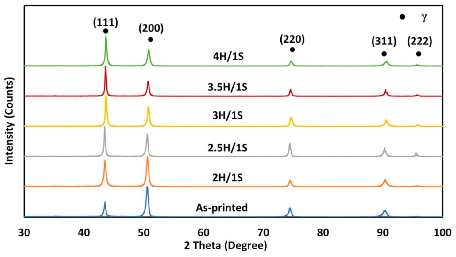
3.2. Texture and Phase Evolution Using XRD Analysis

XRD analysis was employed as an initial characterization and screening method because it provides quick and informative feedback about the microstructural evolution in terms of texture changes and phase precipitation and/or dissolution, which are the main concerns in the optimization process. Figure 5 shows the XRD patterns of the as-printed and heat-treated samples. As can be seen in this figure, the as-printed and 2H/1S conditions exhibited higher peak intensities of γ (200) than those of γ (111), indicating that the 2H/1S treatment did not significantly change the as-printed texture due to a potentially insufficient activation energy. Thus, this condition was excluded from further analysis as it did not allow to achieve the desired texture. However, an increase in the homogenization time to 2.5, 3, 3.5 and 4 h resulted in noticeable changes in the as-printed texture and revealed higher peak intensities of γ (111) as compared to those of γ (200) with intensity ratios (f) of 1.38, 1.51, 2.05 and 1.83, respectively. This means that after a homogenization treatment at 1080 °C for 2.5 h, the as-printed texture was already significantly affected by the homogenization time.
Furthermore, to follow the precipitation/dissolution of phases containing Nb, Ti and Mo, the lattice parameter of γ-matrix in the heat-treated IN718 (2H/1S, 2.5H/1S, 3H/1S, 3.5H/1S and 4H/1S) conditions was calculated, as shown in Figure 6. For comparison, the lattice parameter of γ-matrix in the as-printed condition, as a reference (illustrated by a dashed line), and in the 1H/1S-treated conditions reported in the previous work [22], are included in this figure. As can be seen, the lattice parameter of γ-matrix in the as-printed condition increased from 3.5999 ± 0.0034 Å to 3.6039 ± 0.0016 Å, 3.6031 ± 0.0008 Å and 3.6035 ± 0.0007 Å, after the 1H/1S, 2H/1S and 2.5H/1S conditions, respectively. This can be attributed to the dissolution of the segregated Nb, Ti and Mo (present in the inter-dendritic regions and grain boundaries) back into the γ-matrix, causing an expansion in the lattice, because the atomic size of these elements is 33, 18 and 27.5%, respectively, larger than that of Ni [22]. Such a back-diffusion phenomenon has a beneficial effect on the mechanical properties of the LPBF IN718 alloy as it releases more age-hardening constituents such as Nb and Ti, which are required for the precipitation of γ″ and γ′ phases.
However, the application of the 3H/1S, 3.5H/1S and 4H/1S treatments resulted in a significant reduction in the γ-matrix lattice parameter (Figure 6) relative to the as-printed condition, being 3.5965 ± 0.0015 Å, 3.5964 ± 0.0029 Å and 3.5931 ± 0.0036 Å, respectively. It is interesting to note that the lattice parameter gradually decreases with an increase in the homogenization time to 3, 3.5 and 4 h. This can be explained by the depletion of some alloying elements (Nb and Ti) from γ-matrix during the heat treatments. Therefore, a drop in the mechanical properties after the 3H/1S, 3.5H/1S and 4H/1S heat treatments is expected given the smaller precipitation of γ′ and γ′′ phases. Such a γ-matrix lattice parameter reduction with longer annealing treatments was also reported by Jiang et al. [31]. Accordingly, it can be concluded that the homogenization treatment at 1080 °C for 2.5 h is a threshold whereafter there is a degradation in the hardening due to a depletion of precipitate-forming elements.

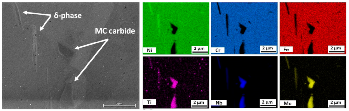
3.3. Microstructure and Elemental Analysis

3.3.1. Precipitates and Grain Morphology Evolution

Figure 7 shows the precipitate distribution in the as-printed and heat-treated conditions. As can be seen in the as-printed micrograph (Figure 7a,b), continuous chains of small regions enriched in segregated elements and Laves phase are distributed along the inter-dendritic and grain boundary zones. The homogenization treatment (1080 °C) is intended to dissolve these segregated elements and detrimental phases, such as Laves phase, whereas the subsequent solution treatment (980 °C) is intended to precipitate δ-phase since the δ-phase precipitation temperature range in IN718 superalloy lies between 750 and 950 °C [32].
After the heat treatments with different homogenization times (2.5, 3, 3.5 and 4 h), these inter-dendritic and grain boundary Laves phase chains are dissolved, allowing a greater release of the segregated elements into γ-matrix, as can be seen in Figure 7c–j. Furthermore, only inter-granular δ-phase precipitated after these heat treatments, indicating a nearly complete dissolution of the Nb-enriched regions inside the grains (inter-dendritic zones). At the end of the solidification stage, the grain boundaries accumulated more segregated elements as compared to the inter-dendritic zones with a higher concentration of Nb, as was previously observed in Figure 7 in [22]. This is because the segregation energy of Nb at the grain boundaries is twice that in the matrix [33]. During the homogenization treatment, the inter-dendritic segregates easily vanished, while retaining a sufficient Nb concentration along the grain boundaries for the precipitation of inter-granular δ-phase during the consecutive solution treatment. Although the heat treatments involved the same solution time (1 h), the amount of the precipitated δ-phase along the grain boundaries decreased as homogenization treatment time increased, as shown in Figure 7d,f,h,j. This is mainly because of the decrease in the Nb concentration along the grain boundaries with such homogenization time increase. However, after these conditions, the image threshold for digitized SEM micrographs must be analyzed using ImageJ software in order to quantify the amount of δ-phase precipitation.
After the 3H/1S, 3.5H/1S and 4H/1S treatments, more irregular-shaped particles were formed along the grain boundaries, as shown in the inset image in Figure 7f,h,j. According to the EDS analysis shown in Figure 8, these particles are highly enriched with Nb (≈51 wt. %) and Ti (≈6.5 wt. %) and, therefore, they have been indexed as MC carbides. These findings are consistent with the results of the γ-matrix lattice parameter analysis, wherein a decrease in the lattice parameter of γ-matrix was observed, due to the depletion of Nb and Ti from the matrix to form MC carbides.
Although the purpose of the homogenization treatment is to dissolve the segregates and to homogenize the elemental distribution in γ-matrix, it can also trigger static recrystallization, which is necessary to refine the as-printed microstructure and consequently improve the mechanical properties of LPBF IN718. As mentioned earlier, in most pertinent literature consulted examines how to homogenize the as-printed microstructure and improve the mechanical properties through the dissolution of the detrimental phases and the precipitation of the strengthening phases (γ′ and γ′′). However, less attention is paid to the grain structure, which must also be known in order to obtain isotropic mechanical properties, especially in the case of a typical elongated grain morphology of the as-printed LPBF IN718.
The high level of residual stresses which are generated due to the rapid and repetitive heating and cooling inherent to the LPBF process is the driving force triggering the static recrystallization process during homogenization treatment [32]. As can be seen in Figure 7c–f, the microstructure after the 2.5 h and 3 h homogenization conditions is mainly composed of a significant number of elongated grains with longitudinal axes parallel to the building direction, surrounded by a small number of equiaxed grains that were concentrated along the grain boundaries of the elongated grains (see Figure 7f). Thus, the mechanical properties of LPBF IN718 are expected to be anisotropic even after the 2.5H/1S and 3H/1S conditions. It is worth mentioning that the microstructure and grain morphology features obtained in this study after the 2.5H/1S and 3H/1S conditions do not match those obtained by some other researchers [34,35], who reported that a complete equiaxed grain IN718 matrix was obtained after a homogenization treatment at 1080 °C for 1.5 h, followed by a solution treatment at 980 °C for 1 h. The discrepancy can be explained by the fact that the variations in the printing process parameters as well as the performed scanning strategies would result in changes in the stored energy from one as-printed material to another, which consequently leads to changes in temperature and incubation time of the static recrystallization process.
In contrast with the 2.5 h and 3 h conditions, after the homogenization treatment for 3.5H/1S, more equiaxed grains with some annealing twins in the grain interiors are observed, as shown in Figure 7g,h. However, elongated grains were still present under this condition, indicating that a longer homogenization time is required to obtain a completely recrystallized material. After the 4H/1S treatment, distinct microstructural changes and dominant equiaxed grains with interior annealing twins are observed, suggesting that the recrystallization process is almost complete, inasmuch as annealing twins exist only in unstrained recrystallized grains [32]. Furthermore, in the current study, the average measured grain size in the completely recrystallized IN718 is 62.5 μm, which is consistent with that obtained in [36] (65 μm) after homogenization treatment at 1150 °C for 2 h, followed by aging treatment (700 °C for 12 h, followed by water cooling) for LPBF IN718.

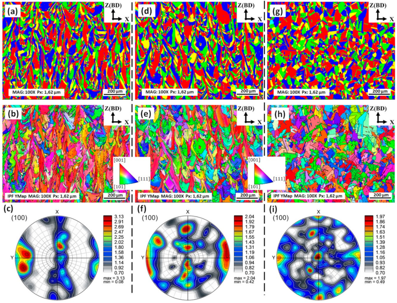
3.3.2. Texture and Grain Structure Evolution

Figure 9 shows the grain morphology, inverse pole figures (IPF) and pole figures (PF) of the as-printed and heat-treated conditions used to investigate the evolution in the crystallographic orientation alignment and grain structure. Based on the XRD and microstructure analyses, the 2.5H/1S and 4H/1S treatment conditions were selected to be analyzed using the EBSD, inasmuch as the 2.5H/1S conditions are the threshold after which the depletion of age-hardening constituents (Nb and Ti) from γ-matrix occurs, while the 4H/1S conditions correspond to those whereafter a near-completely-recrystallized material is obtained.
As can be seen in Figure 9a–c, the alloy in the as-printed conditions exhibit an elongated grain microstructure with a strong fiber texture along the (100) plane, which is parallel to the building direction. Such a textured material and grain morphology are typical of IN718 alloy fabricated by LPBF. After the 2.5H/1S conditions, noticeable changes in the crystallographic orientation are observed, and are shown by a decrease in the red areas in Figure 9e and a lower texture intensity value of the maximum uniform density along the (100) orientation in the pole figure (MUD = 2.04) (Figure 9f). This points to the weakening of the (100) texture, as compared to the as-printed conditions (MUD = 3.13). These results are consistent with those of the XRD analysis (Figure 5). However, the alloy microstructure in the xz-plane (parallel to the building direction) is still composed of columnar grains (Figure 9d), thus indicating no significant changes as compared to the as-printed grain morphology.
Figure 10a,b show the grain aspect ratio histograms of the as-printed 2.5H/1S and 4H/1S conditions extracted from the EBSD data. The aspect ratio reported in this figure corresponds to the grain width-to-length ratio, meaning that the closer this ratio is to 1, the more equiaxed the grains are. As can be seen in this figure, the histogram peaks of the as-printed and 2.5H/1S conditions are observed to be closer to the lower aspect ratio values, indicating the presence of a significant number of columnar grains even after the 2.5H/1S heat treatment. This result suggests that the 2.5H/1S treatment is still insufficient to significantly change the as-printed grain structure, which, once again, is consistent with the microstructure analysis (see Figure 7c,d).
After the 4H/1S treatment, fully recrystallized equiaxed grains with annealing twins are observed, and become the dominant grain morphology as shown in Figure 9g. This state of complete recrystallization is characterized by a relatively weak texture, with an MUD of 1.97 along the (100) plane (Figure 9i) and an orientation of the measured grain map that is less aligned with (100) plane, as compared to the 2.5H/1S and as-printed conditions. In addition, a significant increase in the aspect ratio of the grain structure corresponding to the 4H/1S conditions (Figure 10c) is observed, as indicated by the peak shift towards the higher aspect ratio values, thus suggesting the nucleation of new equiaxed grains via the complete recrystallization process, that is also consistent with the microstructure results (Figure 7i,j).

3.3.3. Misorientation Angle Evolution

The formation of a sub-grain misorientation network during the LPBF solidification process and its evolution under different post-heat treatments strongly affect the mechanical properties of IN718. In this context, Figure 11 shows the evolution of the high- and low-angle grain boundaries (HAGBs and LAGBs) of LPBF IN718 alloy under the as-printed and heat-treated conditions, respectively indicated by the black and red full lines. According to the study by Li et al. [36], the misorientation angles (MAs) between 2° and 15° are identified as LAGBs, whereas angles greater than 15° are defined as HAGBs.
As can be seen in Figure 11a, the microstructure of the as-printed condition contains columnar grains with a relatively high density of LAGBs having a number fraction (NF) of 40.4%. Such a high NF of LAGBs is consistent with the microstructure of the as-printed conditions, wherein the sub-grains are composed of columnar dendrites (Figure 7a,b), that formed during the solidification process, and are divided by the LAGBs. After the 2.5H/1S condition, the density of the LAGBs decreases slightly to 37.8%, which is also consistent with the microstructure results, since most of the substructure features (columnar dendrites) disappear in the micrographs shown in Figure 7c,d. Furthermore, the transformation of some columnar grains to equiaxed grains (incomplete recrystallization process) also contributes to such a slight increase in HAGBs, from 59.6 to 62.1%, at the expense of LAGBs, as can be seen in Figure 11d.
After the 4H/1S treatment, a significant decrease in LAGBs, from 37.8 to 12.4%, is observed, to the benefit of HAGBs, which increase from 62.1 to 87.7%, as shown in Figure 11c,d. This is attributable to a complete elimination of sub-grain features: full recrystallization is achieved after the 4H/1S treatment, since there is a high fraction of annealing twins (MAs ≈ 60°).
Coincidence site lattice (CSL) boundaries are special grain boundaries which are characterized by having specific misorientation values and the reciprocal density of coinciding sites is defined as Ʃ. CSL is widely used to identify twin boundaries and to analyze the grain boundary character distribution [36]. Primary twins, Ʃ3, are characterized by 60° misorientation around the (111) plane, and twins can be formed during either heat treatments or recrystallization. For further tracking of the annealing twins after heat treatments, the NF evolution of the coincidence site lattice (CSL Ʃ3) grain boundaries in the as-printed and heat-treated conditions was investigated, as shown in Figure 11d. It should be noted in this figure that, as compared to the as-printed and 2.5H/1S conditions, the 4H/1S treatment shows a relatively higher fraction (87.1%) of the CSL Ʃ3 grain boundaries, thanks to the presence of a large number of annealing twins. These new annealing twin boundaries may form as a result of the interaction of pre-existing Ʃ3 boundaries during the migration of the grain boundaries or growth accidents at the migration grain boundaries [37].
It is also important to note that the NF of the annealing twins, indicated by CSL Ʃ3, exhibits the same trend as HAGBs as shown in Figure 11d. Such a high fraction of HAGBs and annealing twin boundaries (Σ3) in the interior of the grains indicate that the 4H/1S treatment clearly provides a sufficient activation energy for the grain boundary migration, which results in the material grain boundaries being engineered via the promotion of a near-complete recrystallization process and introduction of annealing twins. The twinned structure in the materials is regarded as one of the grain boundary engineering (GBE) techniques that can significantly improve the mechanical properties of metallic alloys [32,36]. Therefore, improved mechanical properties are expected to be obtained after the application of this heat treatment.
Generally, the Kernel Average Misorientation (KAM) value calculated from the EBSD data can qualitatively reflect the degree of microscopic plastic strain in samples, as indicated by changes in colors, that is nearly associated with the dislocation density, and is strongly linked to the material mechanical properties [32]. Figure 12 shows the evolution of the average KAM value in the as-printed 2.5H/1S and 4H/1S heat-treated conditions with misorientation angle values ranging from 0 to 5°. The blue to red colors in the KAM maps represent the lowest to highest kernel misorientation angles, respectively, as indicated by the color bar below Figure 12d. As seen in Figure 12a, a large local misorientation (0.85°) in the as-printed conditions is observed, indicating the presence of large local plastic strains and high dislocation densities. Such large local plastic stains in the as-printed condition are related to the presence of high residual stresses resulting from high thermal stresses generated during the LPBF printing process. These residual stresses provide the driving force for the static recrystallization process when adequate post-process heat treatments are applied.
After the 2.5H/1S treatment conditions, a slight decrease in the KAM values is observed (0.75°) (see Figure 12b), indicating that the homogenization treatment for 2.5 h is insufficient to completely release the stored distortion energy, and that high plastic strains are still present. When the homogenization time increases to 4 h (4H/1S condition), a significant decrease in the KAM values is observed (0.5°) (see Figure 12c), indicating that more of the stored energy has been released via the annihilation of dislocation tangles. Considering the equiaxed grain morphology (see Figure 9g), along with the low KAM values of the 4H/1S conditions, it can be concluded that the 4H/1S treatment is an adequate post-process heat treatment for LPBF IN718 alloy, since it triggers a complete recrystallization process, accompanied by a significant relief of processing-induced residual stresses.

3.4. Mechanical Properties

3.4.1. Room Temperature Tensile Properties

Figure 13 shows the RT tensile properties of LPBF IN718 alloy in the as-printed and heat-treated conditions. Furthermore, the RT tensile properties of the heat-treated (AMS5662) wrought IN718 reported in [38] are included in this figure for comparison. Detailed average RT mechanical properties values are listed in Table 6. It can be seen that the as-printed samples exhibit the lowest tensile strength (978 MPa), but the highest elongation to failure (29%), as compared to the heat-treated conditions. This is attributable to the ease of dislocation glide and multiplication during the tensile deformation in the absence of the strengthening phases (γ′ and γ′′), resulting in an inferior strength and enhanced ductility. After the 2.5H/1S heat treatment, the TS significantly increases to 1366 MPa, whereas the ductility significantly decreases to 16%. This is due to the precipitation of γ′ and γ′′ phases, which play a crucial role in strengthening the IN718 alloy by interacting with the dislocation movement during deformation. After 4H/1S heat treatment of the LPBF IN718 alloy, the TS is comparable to that of the 2.5H/1S condition (1367 MPa), while the elongation to failure increases (20.3%), as shown in Figure 13. As well, the tensile properties (TS, YS and El) after the both heat-treated conditions exceed those of the wrought alloy [38]. Furthermore, the 4H/1S treatment leads to a significant improvement in plasticity, and provides tensile and yield strengths comparable to those of the conventionally heat-treated LPBF IN718, as shown in Table 6 (heat treatment conditions correspond to the AMS standards [38,39]).
Although the 4H/1S treatment leads to smaller γ-matrix lattice parameters (Figure 6) and lower KAM values (Figure 12c,d) than those after the 2.5H/1S treatment, thus indicating the depletion of the constituents that promote precipitation hardening in the γ-matrix and a decrease in dislocation density, the mechanical strengths are nearly similar, while the plasticity is improved (after 4H/1S treatment). This suggests that the presence of another strengthening mechanism, rather than γ′ and γ′′, contributes to improvements of both the strength and ductility at RT. It has been reported that the material strengthening following precipitation of γ′′ results in a deterioration of the material ductility, also known as the strength-plasticity trade-off phenomenon [36]. To obtain such a good balance between the strength and ductility, a GBE method, such as one introducing annealing twins, can be used, as proposed by Watanabe et al. [40]. In this context, as mentioned earlier, in the 4H/1S treatment, the homogenization treatment at 1080 °C for 4 h significantly affects the grain structure and provides additional activation energy for the grain boundary migration. Thus, a high fraction of annealing twins within the recrystallized grains after the 4H/1S treatment is observed, as evidenced by a high number fraction of CSL and HAGBs (Figure 11d). It has been reported that the presence of a high fraction of annealing twins can effectively block and hinder the dislocation movements during deformation, resulting in material strength improvements [32,36]. Furthermore, an improved material plasticity can be obtained following the sliding of HAGBs [36]. Thus, it is reasonable to expect both a high strength and ductility after the application of the 4H/1S treatment conditions. Furthermore, a relatively lower dislocation density in the recrystallized 4H/1S-treated conditions (Figure 12c) also contributes to a higher ductility, as compared to that of the 2.5H/1S-treated conditions. Therefore, it can be concluded that the 4H/1S heat-treated LPBF IN718 alloy manifests an optimized level of RT mechanical properties, i.e., the highest strength and elongation to failure.

3.4.2. High-Temperature Tensile Testing (650 °C)

Figure 14 shows the high-temperature (650 °C) tensile properties of LPBF IN718 alloy in the as-printed and heat-treated conditions. For comparison, the tensile properties of the wrought IN718 (AMS5662) at 650 °C obtained in [38] are included in this figure. As can be seen in Figure 14, the tensile strength in the as-printed condition is lower than that in the heat-treated conditions, whereas its elongation to failure is the highest. This is consistent with the RT tensile properties, and is once again attributed to the absence of γ′ and γ′′ phases in the as-printed material. After both heat treatments (2.5H/1S and 4H/1S), the TS and YS increased significantly, exceeding those of the heat-treated (AMS5662) wrought IN718, whereas their elongations to failure decrease significantly, and become slightly lower than that of the wrought IN718, and are about ¼ the elongation of the as-printed samples. However, the comparison with the tensile properties of the standard heat-treated LPBF IN718 reported in [34] reveals that the 2.5H/1S and 4H/1S treatments lead to significant improvements in both the strength and elongation to failure at 650 °C, as shown in Table 7. Generally, this is attributed to the precipitation of dispersed strengthening phases (γ′ and γ′′) and intergranular δ-phase, which restrict the motion of dislocations and grain boundaries.
Moreover, notwithstanding the different strengthening mechanisms during both the 2.5H/1S and 4H/1S treatments, they exhibited a similar strength and ductility at 650 °C. Reiterating the KAM and sub-grain maps, the high strength of the 2.5H/1S-treated samples at high temperatures can be related to a combined effect of the incomplete annihilation of the as-printed lattice imperfections (Figure 12b), i.e., the sub-grain structure (Figure 11b,d), where a high number fraction of LAGBs is accompanied by the precipitation of γ′, γ′′ and δ phases. Furthermore, the orientation of the elongated grains along the tensile loading direction also contributes to the ductility of the 2.5H/1S-treated samples. However, after the 4H/1S treatment, the material strengthening is due to a high percentage of annealing twins, as indicated by a relatively high number fraction of the CSL Ʃ3 boundaries and HAGBs (Figure 11d), along with the precipitation of γ′, γ′′ and δ phases. Therefore, despite having quite different microstructures and underlying strengthening mechanisms, the 2.5H/1S- and 4H/1S-treated samples ended up having very similar high-temperature mechanical properties.
Compared with the RT tensile properties, the tensile strength of the as-printed samples at 650 °C decreases moderately by 16%, while the elongation to failure increases significantly by 24% (see Figure 15), which can be explained by a decrease in the grain boundary strength due to a decrease in the grain boundary adhesion between the adjacent grains at elevated temperature [38]. Moreover, the improvement in the material plasticity at elevated temperatures can be explained by the thermal activation of the atoms and vacancies that further promote the plastic deformation via the dislocation slip [38]. Unlike the as-printed samples, the ductility of both the 2.5H/1S and 4H/1S-treated samples was reduced by 37.5 and 50%, respectively, when tested at 650 °C, as opposed to RT (see Figure 15). This could be explained by the well-known high temperature ductility loss phenomenon in nickel-based superalloys [41]. It is worth noting that at 650 °C, the 4H/1S-treated samples exhibit a more significant drop in ductility than the 2.5H/1S-treated samples due to a relatively more intensive precipitation of coarse MC carbides.
Therefore, in situations where the product will be used in RT applications, 4H/1S treatment is recommended, while the 2.5H/1S treatment is recommended for high-temperature applications, but only if having isotropic properties is not mandatory. Having directional solidified material with anisotropic properties has some beneficial effects in some aerospace applications, including providing better creep and thermal fatigue resistance. If an IN718 component is subjected to high mechanical stresses both at room and elevated temperatures (650 °C), 4H/1S treatment is obviously a better choice, especially if the application requires isotropic materials with homogenous mechanical properties. For some other applications wherein IN718 is to be processed by LPBF followed by forging, we recommend the forging process after printing, followed by either the 2.5H/1S or 4H/1S heat treatment.

4. Conclusions

The need to compromise the high-mechanical performance of 3D printed Inconel 718 in order to obtain non-distinctive crystallographic texture is one of the main challenges facing the laser powder bed fusion process specially for applications requiring isotropic properties. DOE was employed in the present study to optimize the soaking times of homogenization and solution treatments that yield high and isotropic mechanical properties of LPBF IN718 components. The main findings of the current study can be summarized as follows:
  • The as-printed microstructure shows an elongated grain morphology with a continuous chain of segregates and Laves phase in the inter-dendritic zones and along the grain boundaries. In addition, a strong texture along the (100) plane is observed.
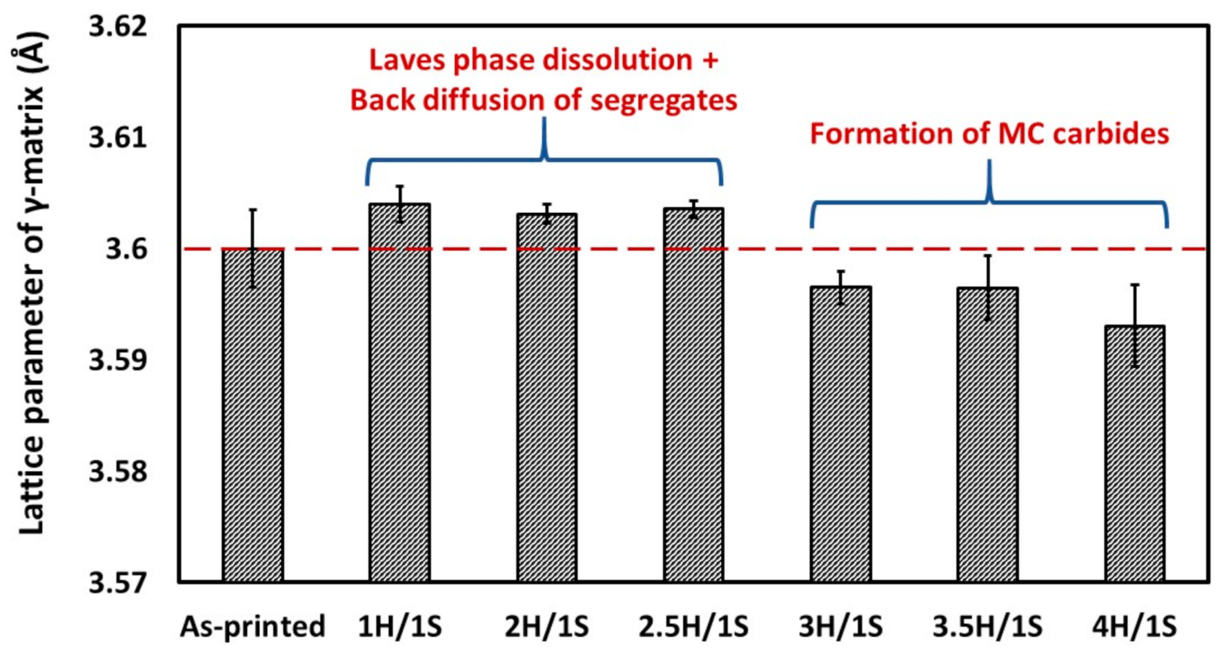
  • After heat treatments, there is a significant back diffusion of the segregated elements and a dissolution of Laves phase. However, a homogenization treatment for more than 2.5 h results in the depletion of the elements (Ti and Nb) necessary for the precipitation of γ′ and γ′′ phases from the γ-matrix, as a drop in the γ-matrix lattice parameter after 3, 3.5 and 4 h-long treatment supports this hypothesis.
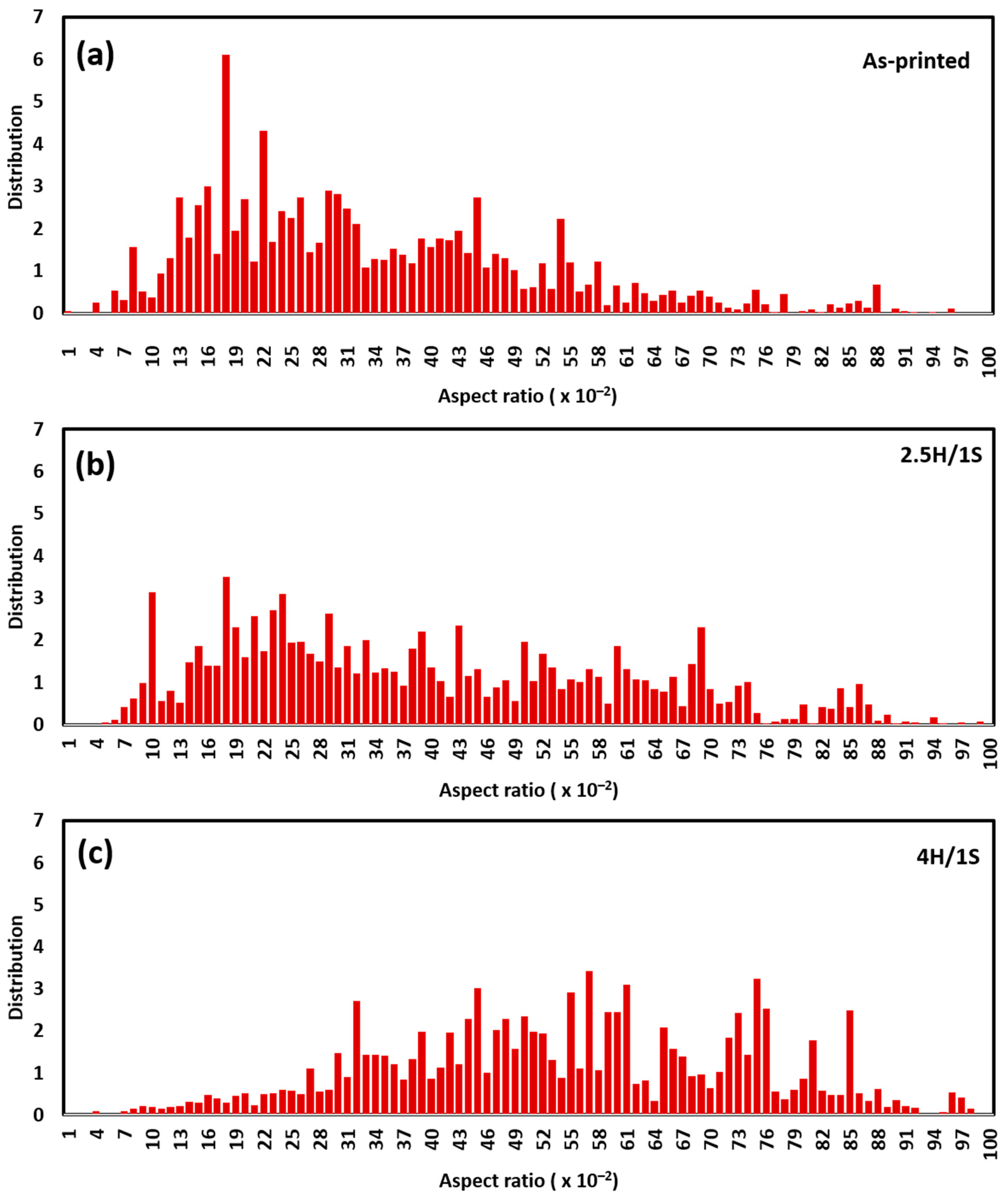
  • Noticeable changes in the preferred crystallographic (100) texture are observed after a 2.5 h homogenization treatment. However, a nearly complete recrystallization with a significantly weakened texture along the (100) direction is obtained after a 4 h homogenization treatment.
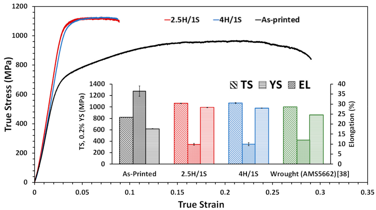
  • At room temperature, the 2.5H/1S and 4H/1S treatments lead to a significant improvement in the tensile properties (TS, YS and El) of LPBF IN718 alloy, as compared to those of the conventionally heat-treated LPBF IN718 (AMS standards) and the wrought (AMS5662) alloy. Moreover, a superior balance between the material strength and ductility is obtained after the 4H/1S treatment due to the presence of a high fraction of annealing twins.
  • Both the 2.5H/1S and 4H/1S-treated samples show comparable strengths at RT and at 650 °C. However, the strengthening mechanisms after both treatments are different: a precipitation hardening combined with the contribution of a primary dislocation network are the strengthening mechanisms during the 2.5H/1S treatment, whereas during the 4H/1S treatment, precipitation hardening becomes the main strengthening mechanism.
  • At 650 °C, the 2.5H/1S- and 4H/1S-treated samples exhibit higher tensile and yield strengths than, and a comparable ductility to those of the (AMS5662) wrought IN718.
  • It is concluded that the 4H/1S treatment offers optimized mechanical properties at RT and at 650 °C and a desirable random crystallographic texture.

Author Contributions

E.M.F. and M.M. conceived and designed the research and its methodology; E.M.F. performed the experimental work; M.M., M.J. and V.B. provided the additive manufacturing (LPBF) tools and characterization facilities; M.S. prepared the EBSD samples and performed the EBSD analysis; E.M.F. and M.M. discussed and analyzed the data; E.M.F. and M.S. discussed and analyzed the EBSD data. D.S. participated in the discussion and the analysis of the tensile testing. M.M., M.J. and V.B. managed and supervised the project; E.M.F. wrote the original draft of the manuscript; M.M., V.B., M.J., M.S. and D.S. revised and edited the paper. All authors have read and agreed to the published version of the manuscript.

Funding

This research is financially supported by the Egyptian Armed Forces and Natural Sciences and Engineering Research Council (NSERC), Canada.

Institutional Review Board Statement

Not applicable.

Informed Consent Statement

Not applicable.

Data Availability Statement

Data is contained within the article.

Conflicts of Interest

The authors declare no conflict of interest.

References

  1. Mostafa, A.; Picazo Rubio, I.; Brailovski, V.; Jahazi, M.; Medraj, M. Structure, texture and phases in 3D printed IN718 alloy subjected to homogenization and HIP treatments. Metals 2017, 7, 196. [Google Scholar] [CrossRef] [Green Version]
  2. Calandri, M.; Yin, S.; Aldwell, B.; Calignano, F.; Lupoi, R.; Ugues, D. Texture and microstructural features at different length scales in Inconel 718 produced by selective laser melting. Materials 2019, 12, 1293. [Google Scholar] [CrossRef] [PubMed] [Green Version]
  3. Luke Nelson, C. Selective Laser Melting of Nickel Superalloys for High Temperature Applications. Ph.D. Thesis, University of Birmingham, Birmingham, UK, 2013. [Google Scholar]
  4. Mostafa, A.; Shahriari, D.; Rubio, I.P.; Brailovski, V.; Jahazi, M.; Medraj, M. Hot compression behavior and microstructure of selectively laser-melted IN718 alloy. Int. J. Adv. Manuf. Technol. 2018, 96, 371–385. [Google Scholar] [CrossRef]
  5. GE Reports Staff 5 Ways GE is Changing the World with 3D Printing. Available online: https://www.ge.com/news/reports/5-ways-ge-changing-world-3d-printing (accessed on 10 November 2019).
  6. Lesyk, D.A.; Martinez, S.; Mordyuk, B.N.; Dzhemelinskyi, V.V.; Lamikiz, А.; Prokopenko, G.I. Post-processing of the Inconel 718 alloy parts fabricated by selective laser melting: Effects of mechanical surface treatments on surface topography, porosity, hardness and residual stress. Surf. Coat. Technol. 2020, 381, 125136. [Google Scholar] [CrossRef]
  7. Hosseini, E.; Popovich, V. A review of mechanical properties of additively manufactured Inconel 718. Addit. Manuf. 2019, 30, 100877. [Google Scholar] [CrossRef]
  8. Bean, G.E.; McLouth, T.D.; Witkin, D.B.; Sitzman, S.D.; Adams, P.M.; Zaldivar, R.J. Build orientation effects on texture and mechanical properties of selective laser melting Inconel 718. J. Mater. Eng. Perform. 2019, 28, 1942–1949. [Google Scholar] [CrossRef]
  9. Newell, D. Solution Anneal Heat Treatments to Enhance Mechanical Performance of Additively Manufactured Inconel 718. Ph.D. Thesis, Air Force Institute of Technology, Dayton, OH, USA, 2020. [Google Scholar]
  10. Huang, W.; Yang, J.; Yang, H.; Jing, G.; Wang, Z.; Zeng, X. Heat treatment of Inconel 718 produced by selective laser melting: Microstructure and mechanical properties. Mater. Sci. Eng. A 2019, 750, 98–107. [Google Scholar] [CrossRef]
  11. Shi, R.; Khairallah, S.A.; Roehling, T.T.; Heo, T.W.; McKeown, J.T.; Matthews, M.J. Microstructural control in metal laser powder bed fusion additive manufacturing using laser beam shaping strategy. Acta Mater. 2020, 184, 284–305. [Google Scholar] [CrossRef]
  12. Raghavan, N.; Simunovic, S.; Dehoff, R.; Plotkowski, A.; Turner, J.; Kirka, M.; Babu, S. Localized melt-scan strategy for site specific control of grain size and primary dendrite arm spacing in electron beam additive manufacturing. Acta Mater. 2017, 140, 375–387. [Google Scholar] [CrossRef]
  13. Roehling, T.T.; Wu, S.S.Q.; Khairallah, S.A.; Roehling, J.D.; Soezeri, S.S.; Crumb, M.F.; Matthews, M.J. Modulating laser intensity profile ellipticity for microstructural control during metal additive manufacturing. Acta Mater. 2017, 128, 197–206. [Google Scholar] [CrossRef]
  14. Deng, D.; Peng, R.L.; Brodin, H.; Moverare, J. Microstructure and mechanical properties of Inconel 718 produced by selective laser melting: Sample orientation dependence and effects of post heat treatments. Mater. Sci. Eng. A 2018, 713, 294–306. [Google Scholar] [CrossRef]
  15. Chlebus, E.; Gruber, K.; Kuźnicka, B.; Kurzac, J.; Kurzynowski, T. Effect of heat treatment on the microstructure and mechanical properties of Inconel 718 processed by selective laser melting. Mater. Sci. Eng. A 2015, 639, 647–655. [Google Scholar] [CrossRef]
  16. Vilaro, T.; Colin, C.; Bartout, J.D.; Nazé, L.; Sennour, M. Microstructural and mechanical approaches of the selective laser melting process applied to a nickel-base superalloy. Mater. Sci. Eng. A 2012, 534, 446–451. [Google Scholar] [CrossRef]
  17. Kuo, Y.-L.; Horikawa, S.; Kakehi, K. Effects of build direction and heat treatment on creep properties of Ni-base superalloy built up by additive manufacturing. Scr. Mater. 2017, 129, 74–78. [Google Scholar] [CrossRef]
  18. Li, X.; Shi, J.; Wang, C.; Cao, G.; Russell, A.; Zhou, Z.; Li, C.; Chen, G. Effect of heat treatment on microstructure evolution of Inconel 718 alloy fabricated by selective laser melting. J. Alloys Compd. 2018, 764, 639–649. [Google Scholar] [CrossRef]
  19. Diepold, B.; Vorlaufer, N.; Neumeier, S.; Gartner, T.; Göken, M. Optimization of the heat treatment of additively manufactured Ni-base superalloy IN718. Int. J. Miner. Metall. Mater. 2020, 27, 640–648. [Google Scholar] [CrossRef]
  20. Pande, C.S.; Rath, B.B.; Imam, M.A. Effect of annealing twins on Hall–Petch relation in polycrystalline materials. Mater. Sci. Eng. A 2004, 367, 171–175. [Google Scholar] [CrossRef]
  21. Yuan, Y.; Gu, Y.; Cui, C.; Osada, T.; Yokokawa, T.; Harada, H. A Novel strategy for the design of advanced engineering alloys—Strengthening turbine disk superalloys via twinning structures. Adv. Eng. Mater. 2011, 13, 296–300. [Google Scholar] [CrossRef]
  22. Fayed, E.; Shahriari, D.; Saadati, M.; Brailovski, V.; Jahazi, M.; Medraj, M. Influence of homogenization and solution treatments time on the microstructure and hardness of Inconel 718 fabricated by laser powder bed fusion process. Materials 2020, 13, 2574. [Google Scholar] [CrossRef]
  23. Fayed, E.; Shahriari, D.; Saadati, M.; Brailovski, V.; Jahazi, M.; Medraj, M. Effect of homogenization and solution treatments time on the elevated-temperature mechanical behavior of Inconel 718 fabricated by laser powder bed fusion. Sci. Rep. 2021. [Google Scholar]
  24. Anderson, H.; Carriere, J.; Vaughn, N.; Kraber, J.; Sobczyk, P. Design Expert Software; Stat-Ease Inc.: Minneapolis, MN, USA, 2019. [Google Scholar]
  25. Beausir, J.-J. Fundenberger Analysis Tools for Electron and X-Ray Diffraction; ATEX—Software; Université de Lorraine: Metz, France, 2017. [Google Scholar]
  26. Bruker Nano GmbH. Quantax Esprit Software; Bruker Nano GmbH: Berlin, Germany, 2015. [Google Scholar]
  27. Zhang, H.; Gu, D.; Ma, C.; Guo, M.; Yang, J.; Wang, R. Effect of post heat treatment on microstructure and mechanical properties of Ni-based composites by selective laser melting. Mater. Sci. Eng. A 2019, 765, 138294. [Google Scholar] [CrossRef]
  28. Ni, M.; Chen, C.; Wang, X.; Wang, P.; Li, R.; Zhang, X.; Zhou, K. Anisotropic tensile behavior of in situ precipitation strengthened Inconel 718 fabricated by additive manufacturing. Mater. Sci. Eng. A 2017, 701, 344–351. [Google Scholar] [CrossRef]
  29. Zhang, D.; Feng, Z.; Wang, C.; Wang, W.; Liu, Z.; Niu, W. Comparison of microstructures and mechanical properties of Inconel 718 alloy processed by selective laser melting and casting. Mater. Sci. Eng. A 2018, 724, 357–367. [Google Scholar] [CrossRef]
  30. Tucho, W.M.; Cuvillier, P.; Sjolyst-Kverneland, A.; Hansen, V. Microstructure and hardness studies of Inconel 718 manufactured by selective laser melting before and after solution heat treatment. Mater. Sci. Eng. A 2017, 689, 220–232. [Google Scholar] [CrossRef]
  31. Jiang, R.; Mostafaei, A.; Pauza, J.; Kantzos, C.; Rollett, A.D. Varied heat treatments and properties of laser powder bed printed Inconel 718. Mater. Sci. Eng. A 2019, 755, 170–180. [Google Scholar] [CrossRef]
  32. Cao, Y.; Bai, P.; Liu, F.; Hou, X.; Guo, Y. Effect of the solution temperature on the precipitates and grain evolution of IN718 fabricated by laser additive manufacturing. Materials 2020, 13, 340. [Google Scholar] [CrossRef] [Green Version]
  33. Connétable, D.; Ter-Ovanessian, B.; Andrieu, É. Diffusion and segregation of niobium in fcc-nickel. J. Phys. Condens. Matter 2012, 24, 095010. [Google Scholar] [CrossRef]
  34. Zhao, J.-R.; Hung, F.-Y.; Lui, T.-S. Microstructure and tensile fracture behavior of three-stage heat treated Inconel 718 alloy produced via laser powder bed fusion process. J. Mater. Res. Technol. 2020, 9, 3357–3367. [Google Scholar] [CrossRef]
  35. Strößner, J.; Terock, M.; Glatzel, U. Mechanical and microstructural investigation of nickel-based superalloy IN718 manufactured by selective laser melting (SLM). Adv. Eng. Mater. 2015, 17, 1099–1105. [Google Scholar] [CrossRef]
  36. Li, X.; Shi, J.J.; Cao, G.H.; Russell, A.M.; Zhou, Z.J.; Li, C.P.; Chen, G.F. Improved plasticity of Inconel 718 superalloy fabricated by selective laser melting through a novel heat treatment process. Mater. Des. 2019, 180, 107915. [Google Scholar] [CrossRef]
  37. Dave VanAken Engineering Concepts: Formation of Annealing Twins. Available online: https://www.industrialheating.com/articles/86154-engineering-concepts-formation-of-annealing-twins (accessed on 27 January 2020).
  38. Gao, Y.; Zhang, D.; Cao, M.; Chen, R.; Feng, Z. Effect of δ phase on high temperature mechanical performances of Inconel 718 fabricated with SLM process. Mater. Sci. Eng. A 2019, 767, 138327. [Google Scholar] [CrossRef]
  39. Zhang, D.; Niu, W.; Cao, X.; Liu, Z. Effect of standard heat treatment on the microstructure and mechanical properties of selective laser melting manufactured Inconel 718 superalloy. Mater. Sci. Eng. A 2015, 644, 32–40. [Google Scholar] [CrossRef]
  40. Watanabe, T. An approach to grain boundary design for strong and ductile polycrystals. Res. Mech. 1984, 11, 47–84. [Google Scholar]
  41. Kreitcberg, A.; Brailovski, V.; Turenne, S. Elevated temperature mechanical behavior of IN625 alloy processed by laser powder-bed fusion. Mater. Sci. Eng. A 2017, 700, 540–553. [Google Scholar] [CrossRef]
Figure 1. (a) LPBF building platform illustrating the orientation of the as-printed coupons with respect to the building direction (BD); (b) geometry and dimensions of the microstructure and tensile samples; (c) schematic drawing showing the scanning strategy utilized in the present study. (a) and (b) were also used in [22]. All dimensions in (b) are in mm.
Metals 11 00144 g001
Figure 2. Three-dimensional (3D) response surfaces of the effect of the interaction between the homogenization and solution treatment times on: (a) TS, (b) YS and (c) El (all at 650 °C), (d) Vickers microhardness (room temperature), and (e) texture degree
Metals 11 00144 g002
Figure 3. Contour lines curves: (a) maximum desirability function and predicted values of (b) TS, (c) YS, (d) El, (e) Vickers microhardness, and (f) texture degree.
Metals 11 00144 g003
Figure 4. (a) Schematic drawing illustrating the position of the new proposed treatment conditions within the treatment time window with respect to the previous treatments; (b) the full regime of the heat treatment cycle applied in the current study.
Metals 11 00144 g004
Figure 5. X-ray diffraction of the LPBF IN718 in the as-printed and heat-treated conditions.
Metals 11 00144 g005
Figure 6. Lattice parameter evolution of the as-printed γ-matrix as a function of the heat treatment conditions.
Metals 11 00144 g006
Figure 7. SEM micrographs of the vertical (xz) plane of LPBF IN718 under: (ab) as-printed, (cd) 2.5H/1S, (ef) 3H/1S, (gh) 3.5 H/1S and (ij) 4H/1S conditions.
Metals 11 00144 g007
Figure 8. EDS elemental distribution in MC carbides and δ-phase.
Metals 11 00144 g008
Figure 9. EBSD grain map, inverse pole figure (IPF) and pole figure (PF) of LPBF IN718 under: (ac) as-printed, (df) 2.5H/1S treatment, and (gi) 4H/1S treatment conditions. The EBSD mappings of the as-printed and heat-treated samples were plotted using the y-based projected IPF. (a) and (b) were used also in [22].
Metals 11 00144 g009
Figure 10. Evolution of the grains’ aspect ratio with the heat treatment conditions: (a) as-printed; (b) 2.5H/1S; (c) 4H/1S.
Metals 11 00144 g010
Figure 11. Evolution of the misorientation distribution of LAGBs (2° < θ < 15°) and HAGBs (θ > 15°) under different conditions: (a) as-printed, (b) 2.5H/1S, (c) 4H/1S, and (d) the evolution of the number fraction of LAGBs, HAGBs and coincidence site lattice (CSL Ʃ3) grain boundaries under the aforementioned conditions. The LAGBs and HAGBs are indicated by the red and black full lines, respectively, in (ac).
Metals 11 00144 g011
Figure 12. Evolution of the kernel average misorientation angles (KAM) of the LPBF IN718 under (a) as-printed, (b) 2.5H/1S, and (c) 4H/1S conditions and (d) the number fraction of KAM under as-printed and aforementioned heat treatment conditions.
Metals 11 00144 g012
Figure 13. Room temperature tensile properties of the LPBF IN718 in as-printed and heat-treated conditions. For comparison, the RT tensile properties of wrought IN718 (AMS5662) [38] are included.
Metals 11 00144 g013
Figure 14. High-temperature (650 °C) tensile properties of LPBF IN718 in as-printed and heat-treated conditions. For comparison, the high temperature (650 °C) tensile properties of wrought IN718 (AMS5662) [38] are included.
Metals 11 00144 g014
Figure 15. Comparison of the RT and 650°C elongations to failure of the as-printed and heat-treated LPBF IN718 samples illustrating the elevated-temperatures ductility loss.
Metals 11 00144 g015
Table 1. Nominal chemical composition of the as-received gas atomized IN718 powder.
ElementNiCrNbMoTiAlFe + Traces
wt.%49.1919.044.922.701.080.33Bal.
Table 2. LPBF process parameters used in the present study.
Process ParameterValue
Laser power (Watt)285
Laser scanning velocity (mm/s)1000
Laser beam diameter (μm)100
Layer thickness (μm)40
Hatching space (μm)110
Hatch angle (degree)67
Building plate pre-heating temperature (°C)80
Table 3. Details of heat treatment conditions and the corresponding tensile properties at 650 °C (TS, YS and El), hardness measurements and texture degree [22,23].
Heat Treatment ConditionsTensile Properties at 650 °CHV (0.5/15)Texture Degree
Homogenization
(at 1080 °C)
Solution
(at 980 °C)
AgingTS(MPa)YS(MPa)El (%)
1 h/AC *15 min/AC720 °C/8 h/FC **
at 55 °C/h to 620 °C
+ 620 °C/8 h/AC
1038 ± 14976 ± 911.2 ±2525 ± 80.83
1 h/AC1 h/AC1074 ± 281001 ± 1211.8 ± 0.3513 ± 90.57
4 h/AC37.5 min/AC1017 ± 11927 ± 28.2 ± 0.2496 ± 71.84
7 h/AC15 min/AC986 ± 14901 ± 77.4 ± 0.9454 ± 172.38
7 h/AC1 h/AC994 ± 11909 ± 87.3 ± 1460 ± 131.96
* AC: air cooling, ** FC: furnace cooling.
Table 4. Details of multi-objective optimization target and criteria.
Variables/ReponsesInput/OutputCriterionLimitImportance
LowerUpper
VariablesHomogenization soaking time (h)In range17
Solution soaking time (min)In range1560
ResponsesTensile strength, TS (MPa)Maximize98610745
Yield strength, YS (MPa)Maximize90110015
Elongation, El (%)Maximize7125
Vickers Microhardness (HV0.5/15)Maximize4545255
Texture degree, f (ratio)In range>12.45
Table 5. Details of proposed heat treatments conditions in the present study.
DesignationHomogenization Heat Treatment (H)Solution Heat Treatment (S)Aging Heat Treatment
As-printedNoneNoneNone
2H/1S1080 °C for 2 h/AC
|
980 °C for 1 h/AC
|

|
720 °C/8 h/FC at 55 °C/h to 620 °C + 620 °C/8 h/AC
2.5H/1S1080 °C for 2.5 h/AC
3H/1S1080 °C for 3 h/AC
3.5H/1S1080 °C for 3.5 h/AC
4H/1S1080 °C for 4 h/AC
Table 6. RT tensile strength (TS), yield strength (YS) and elongation to failure (El) values in the as-printed and heat-treated conditions. The RT tensile properties reported in [34,38,39] are included for comparison.
Material ConditionTS (MPa)YS (MPa)El (%)Reference
As-printed978 ± 6678 ± 729 ± 1.5
2.5H/1S1366 ± 81250 ± 816 ± 0.5This work
4H/1S1367 ± 71234 ± 920 ± 0.5
Wrought AMS56621280103012[38]
Wrought AMS56621276103412.1[39]
Cast AMS53838627585[39]
LPBF IN718 AMS56621370108410.1[38]
LPBF IN718 AMS56621380124015.5[34]
LPBF IN718 ASM53831371104612.3[38,39]
LPBF IN718 ASM53831350123813[34]
Table 7. Elevated-temperature (650 °C) tensile strength (TS), yield strength (YS) and elongation to failure (El) values of the as-printed and heat-treated conditions. The tensile properties at 650 °C reported in [34,38] are included for comparison.
Material ConditionTS (MPa)YS (MPa)El (%)Reference
As-printed820 ± 2617 ± 436 ± 3
2.5H/1S1063 ± 6991 ± 510 ± 0.4This work
4H/1S1069 ± 8979 ± 310 ± 0.8
Wrought AMS5662100086212[38]
LPBF IN718 AMS566210259155.5[34]
LPBF IN718 ASM538310209503.5[34]
Publisher’s Note: MDPI stays neutral with regard to jurisdictional claims in published maps and institutional affiliations.

