Article

Optimization Study of Post-Weld Heat Treatment for 12Cr1MoV Pipe Welded Joint

1
College of Mechanical and Electronic Engineering, Shandong University of Science and Technology, Qingdao 266590, China
2
Shandong Branch of Guangzhou Zoneteam Architectural Design & Urban Planning Institute Co., Ltd., Jinan 250013, China
3
College of New Energy, China University of Petroleum (East China), Qingdao 266580, China
*
Author to whom correspondence should be addressed.
Metals 2021, 11(1), 127; https://doi.org/10.3390/met11010127
Submission received: 14 December 2020 / Revised: 4 January 2021 / Accepted: 7 January 2021 / Published: 10 January 2021
(This article belongs to the Special Issue Heat Treatment and Mechanical Properties of Metals and Alloys)

Abstract

:
In order to clarify the role of different post-weld heat treatment processes in the manufacturing process, welding tests, post-weld heat treatment tests, and finite element analysis (FEA) are carried out for 12C1MoV steel pipes. The simulated temperature field and residual stress field agree well with the measured results, which indicates that the simulation method is available. The influence of post-weld heat treatment process parameters on residual stress reduction results is further analyzed. It is found that the post weld dehydrogenation treatment could not release residual stress obviously. However, the residual stress can be relieved by 65% with tempering treatment. The stress relief effect of “post weld dehydrogenation treatment + temper heat treatment” is same with that of “temper heat treatment”. The higher the temperature, the greater the residual stress reduction, when the peak temperature is at 650–750 °C, especially for the stress concentration area. The longer holding time has no obvious positive effect on the reduction of residual stress.

1. Introduction

Welding technology has the advantages of wide adaptability and cost saving, is widely used in the construction of key components of thermal power units such as steam pipe, superheater, reheater, and so on. However, due to welding imperfections, welding residual stress, mismatched local performance, and brittle structures in heat-affected zone, welded joints are generally regarded as weak links on the component [1,2,3,4,5]. With the continuous improvement of welding technology and non-destructive testing methods, welding imperfections have be effectively controlled in the manufacturing process. In the design process, the local non-uniform microstructure and mismatched mechanical property of the welded joint can also be considered effectively by introducing the weld coefficient. However, there are still some controversies and uncertainties in the understanding of welding residual stress and its effect evaluation. Welding residual stress is one of the key causes for stress corrosion cracking of weldments [6]. Tensile residual stress is considered to be the critical factor in increasing the sensitivity of fatigue damage of welded joints [7]. Premature failure and fracture of welded joints caused by welding residual stress usually occurred [8,9]. Therefore, it is required to reduce welding residual stress. Up to now, there are many methods to reduce welding residual stress including pre-heating [10], temper bead welding [11], post-weld heat treatment, hammering, vibration aging, ultrasonic impact, and so on. Compared with other methods, post-weld heat treatment can not only reduce the welding residual stress effectively, but also improve the mechanical performance of the welded joint [12,13,14,15,16]. Therefore, post-weld heat treatment is the main method to eliminate welding residual stress in engineering application.
There are several post-weld heat treatment processes, such as dehydrogenation heat treatment (DHT), normalizing heat treatment, tempering heat treatment, et al., in actual industrial production. How to choose suitable heat treatment processes according to material properties and welding characteristics is an important issue for manufacturer. The effect of DHT on the welding residual stress of high-strength steel was studied by Xue et al. [17], and the results showed that the DHT can reduce the residual stress slightly. Comparative study on different heat treatment processes of API X60 grade steel was conducted by Khalaj et al. [18]. They found that the post-weld heat treatment process composed of two-steps of “quenching + tempering” is more effective and reasonable than the traditional one-step normalizing heat treatment. It is worth noting that an improperly designed post-weld heat treatment process is not only the loss of effect of reducing of residual stress, but also has negative effects. Chen et al. [19] found that an unreasonable post-weld heat treatment process would lead to uneven temperature distribution of 12Cr1MoV pipeline, which would introduce harmful thermal stress leading to cracking of welded joint. Furthermore, the influence of post-weld heat treatment on mechanical properties should also be considered. Based on Chen’s investigation, it is found that qualified welded joints can be obtained by DHT at 200 °C × 2 h, but stress relief heat treatment at 600 °C × 2 h will worsen the performance of welded joints.
Currently, experimental testing and finite element simulation are main means to evaluate residual stress reduction effect. Olabi [14] et al. measured the residual stress of low-carbon steel welded joint before and after post-weld heat treatment by using the blind-hole method. The results showed that the residual stress is reduced by 70% after post-weld heat treatment. Paddea et al. [20] obtained the residual stress distribution of P91 steel pipe welded joint by neutron diffraction method. The results are as follows: prior to post-weld heat treatment, the highest tensile residual stress of about 600 MPa was found at the boundary between the heat-affected zone (HAZ) and adjacent parent material, and at the weld root near the inner surface of the pipe. The location of the highest tensile stress after post-weld heat treatment (PWHT) was still near the HAZ, about 120 MPa. Dong et al. [21] investigated the effects of post-weld heat treatment process parameters including peak temperature, holding time and component thickness on residual stress through numerical simulation, and the results showed that peak temperature is the main factor affecting stress relief. Qian et al. [22] studied influences of post-weld heat treatment from different criteria at home and abroad on the residual stress and energy consumption. They found that the heat treatment process from the criteria of ASME-Ⅷ is the best. However, most of the current research about multiple post-weld heat treatment cycles is focus on its effect on the microstructure and mechanical properties of welded joints [23,24,25]. On the country, there is no much detailed study on evolution of residual stress during multiple post-weld heat treatment cycles. Therefore, it is of great significance to study the influence of various post-weld heat treatment processes on the residual stress of welded joints.
In the present work, welding tests, post-weld heat treatment tests, and finite element analysis (FEA) are carried out for 12C1MoV steel pipes clarify the role of different post-weld heat treatment processes in the manufacturing process. The evolution of residual stress distribution of the welded joint during welding and post-weld heat treatment processes were studied through experimental and numerical methods. The influence of post-weld heat treatment process parameters on residual stress reduction results is further analyzed. The tensile properties of welded joints subjected to different heat treatment conditions were measured by tensile experiments. This study aims to provide a theoretical basis for the design and optimization of post-weld heat treatment process.

2. Materials and Experimental Procedure

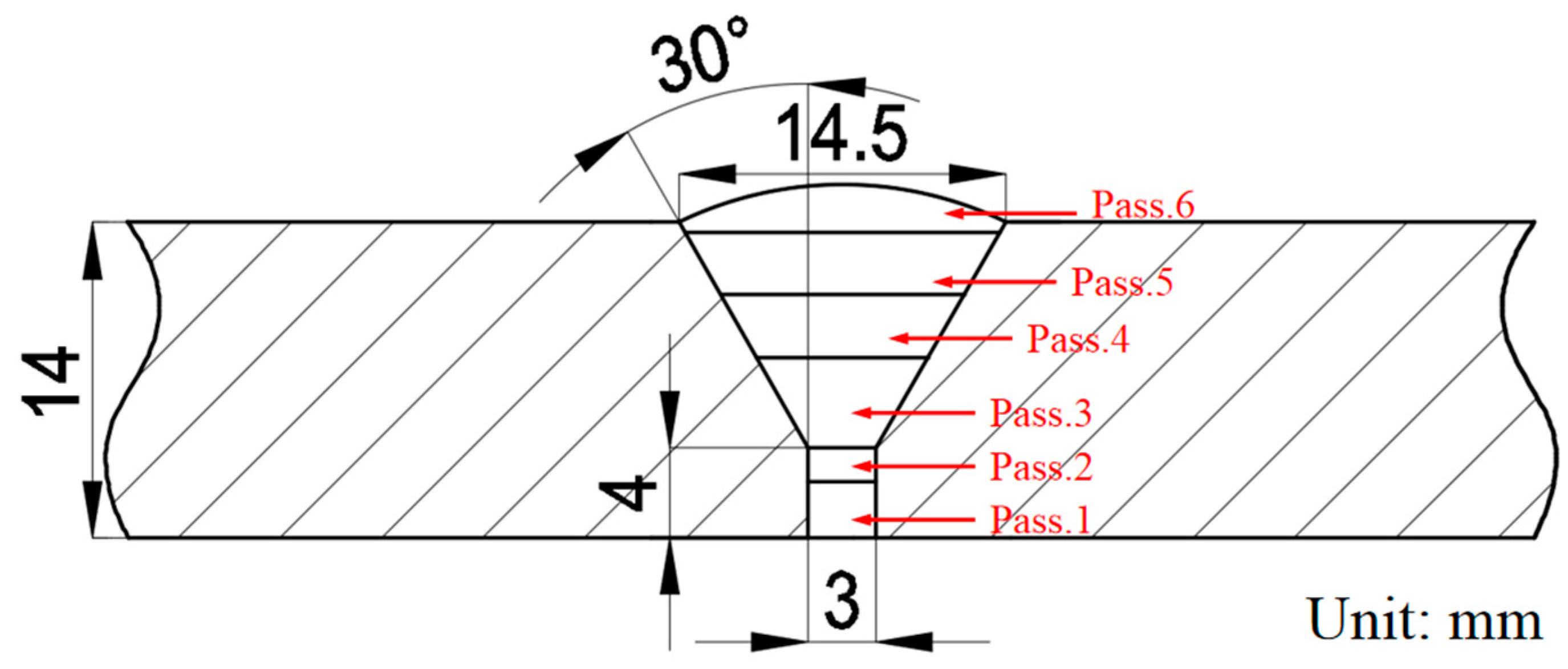
2.1. Materials and Welding Process

The welded joint was manufactured by joining two sections of 12Cr1MoV steel pipe with the size of Φ168 mm × 14 mm × 200 mm. A V-shaped groove with 30° for the butt joint was selected with the width of 3 mm at bottom. The welding groove and welding passes distribution are shown in Figure 1. Totally, 6 welding passes were used for the 12Cr1MoV steel welded pipe specimen. According to the welding sequence, they are marked as Pass.1~Pass.6 (seen in Figure 1). There is only a 3 mm gap at the root of the welding groove as shown in Figure 1. Hence, welding rod with small diameter of 3.2 mm is used for the welding passes marked as Pass.1 and Pass.2. It is worth noting that the welding current used for Pass.2 is adjusted according the height of Pass.1 to ensure fulfill the root of the welding groove. The last welding pass, i.e., Pass.6, is the cap pass. Its width is 14.5 mm and height is about 2 mm (excluding weld reinforcement). R317 was selected as the filler metal in the experiment, the detailed chemical compositions (wt. %) of base metal (12Cr1MoV) and electrode (R317) are listed in Table 1 (provided by the manufacturer). Before welding, pipe surface cleaning was conducted to remove oils and rusts. Then, pre-heat treatment with temperature of 200 °C was performed, as shown in Figure 2. Finally, shielded metal arc welding (SMAW) was used to fabricate the welded joint. Technological parameters of the welding process are listed in Table 2.

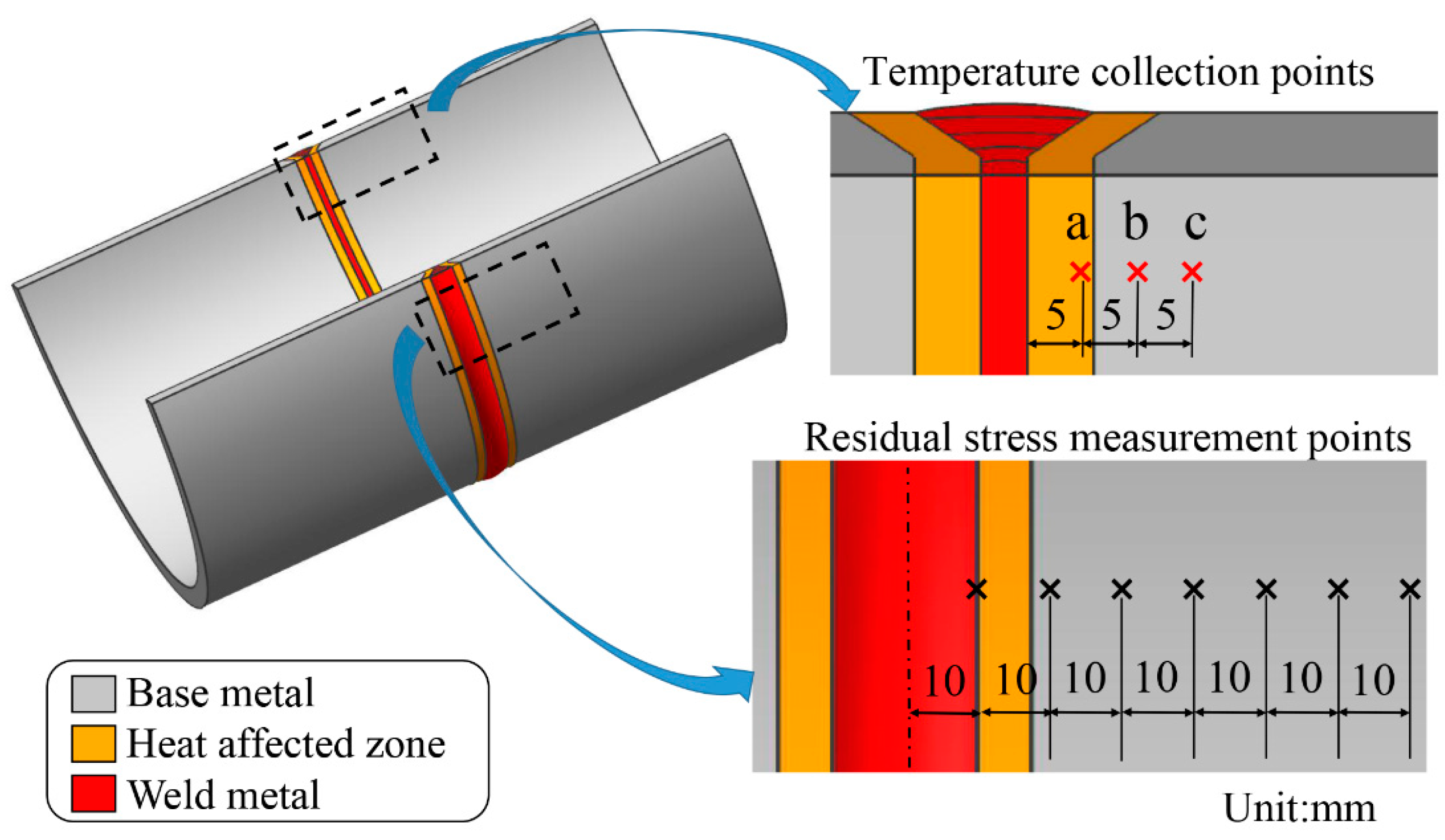
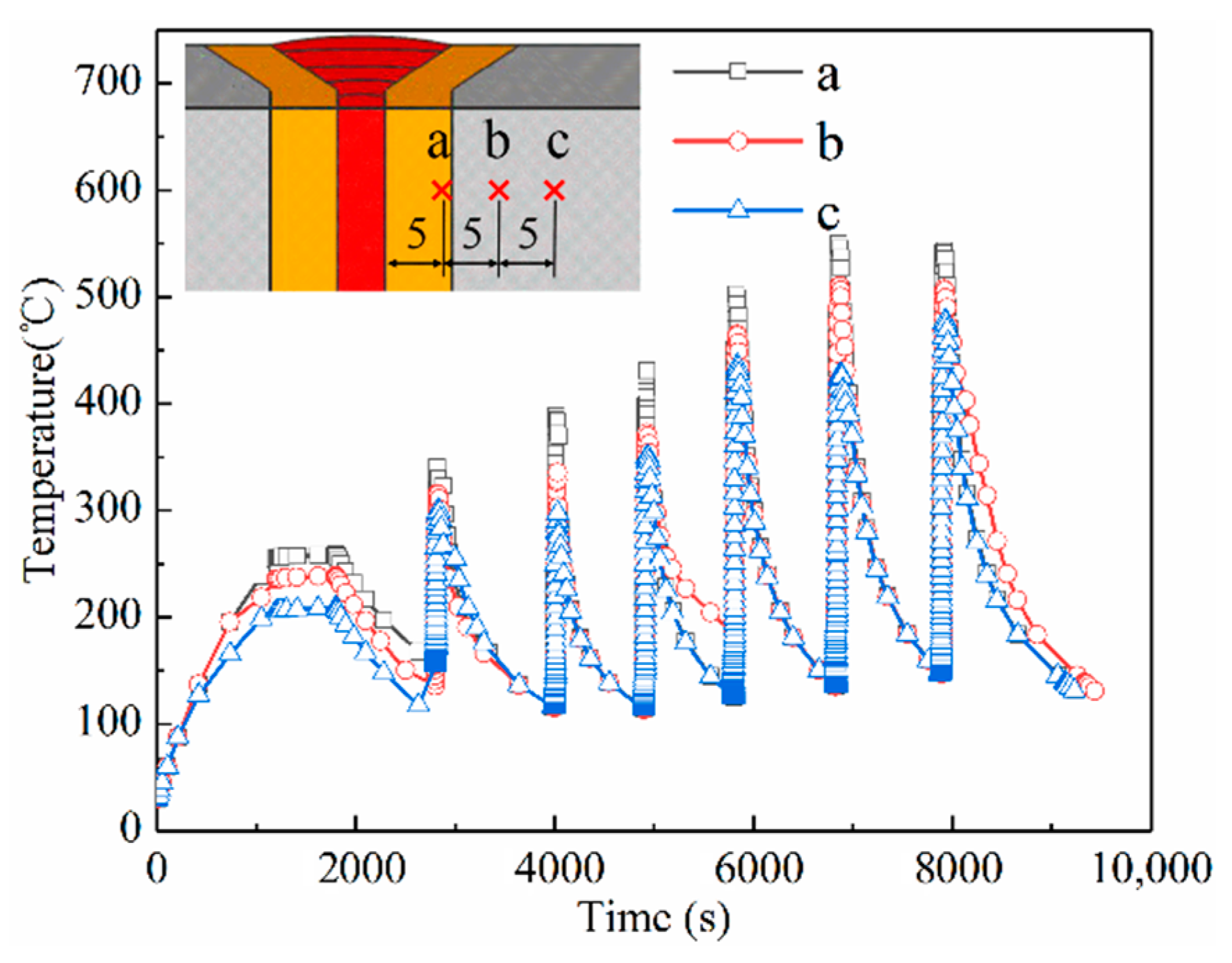
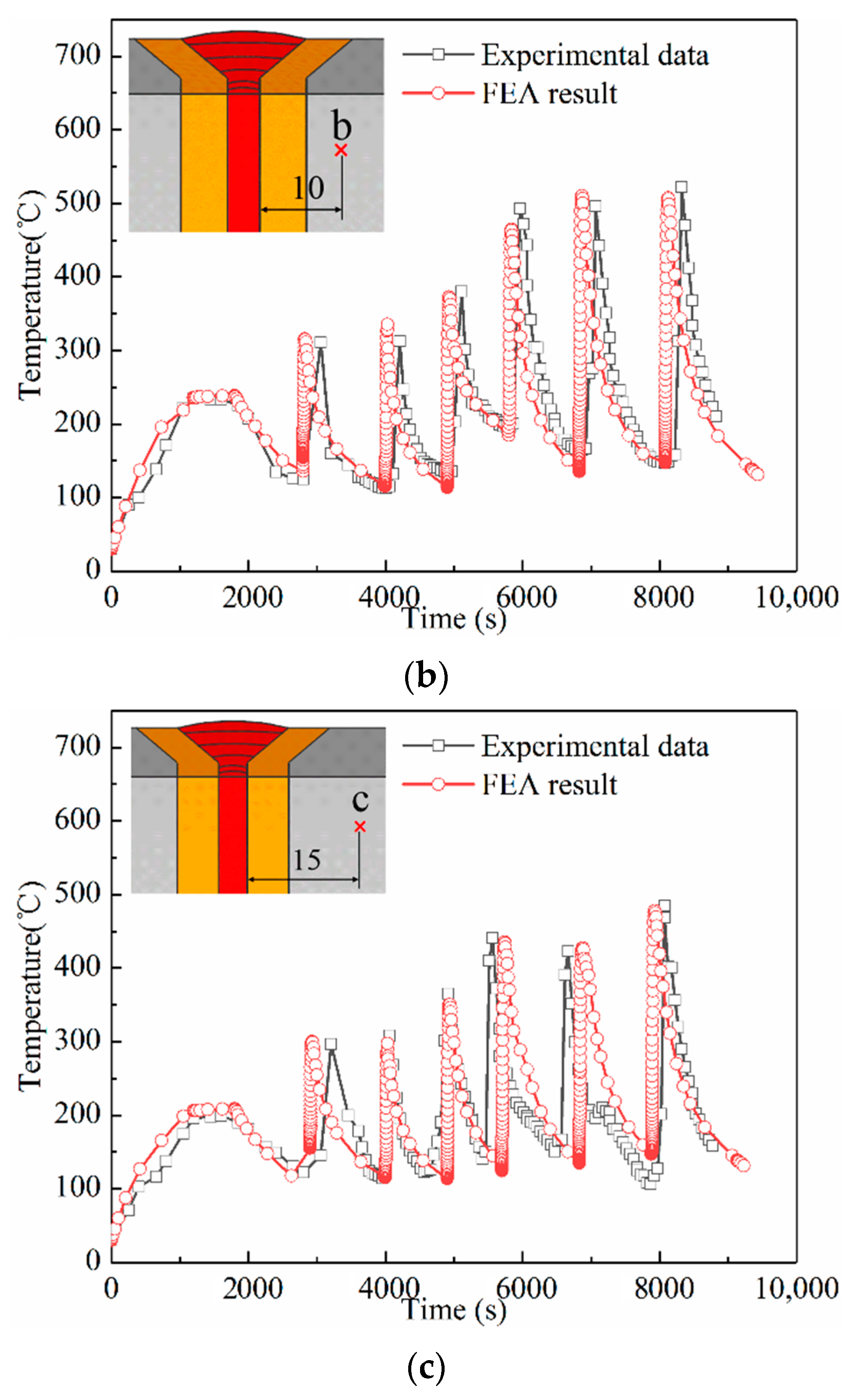
2.2. Measurement of Welding Heat Cycle Curve

In order to verify the simulated temperature field during the welding process, the welding heat cycle curve was measured by thermocouples (see Figure 2). Three WRNK-191 armored K-type thermocouples were attached to the points marked as “a”, “b”, and “c” in Figure 3. The transient temperatures of measured points were acquired and recorded by HPDJ-8125 dynamic data acquisition and analysis system.

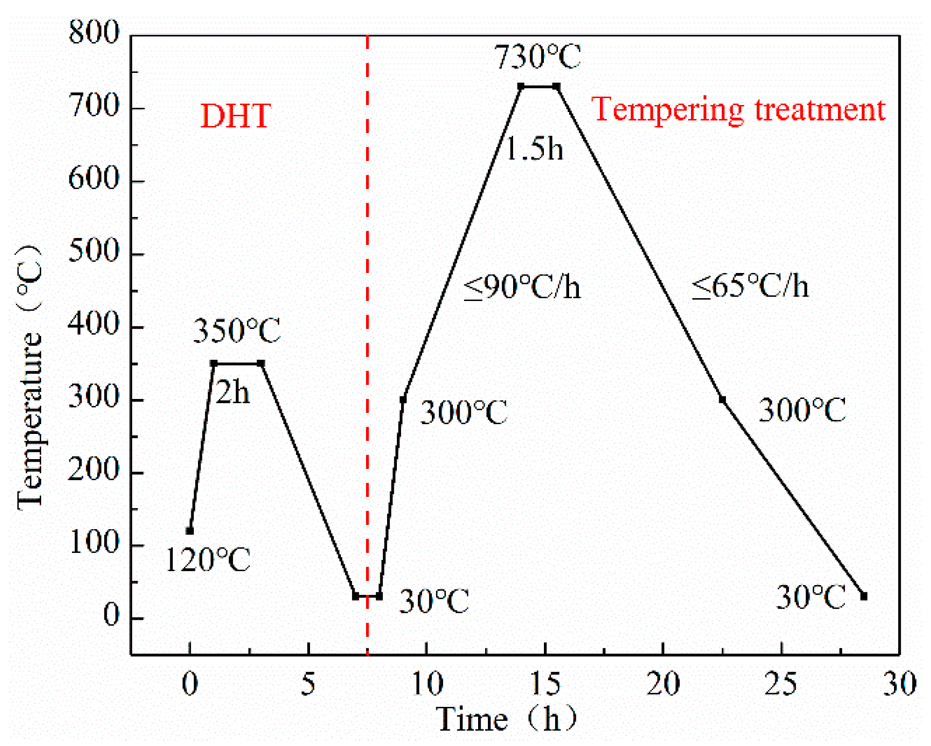
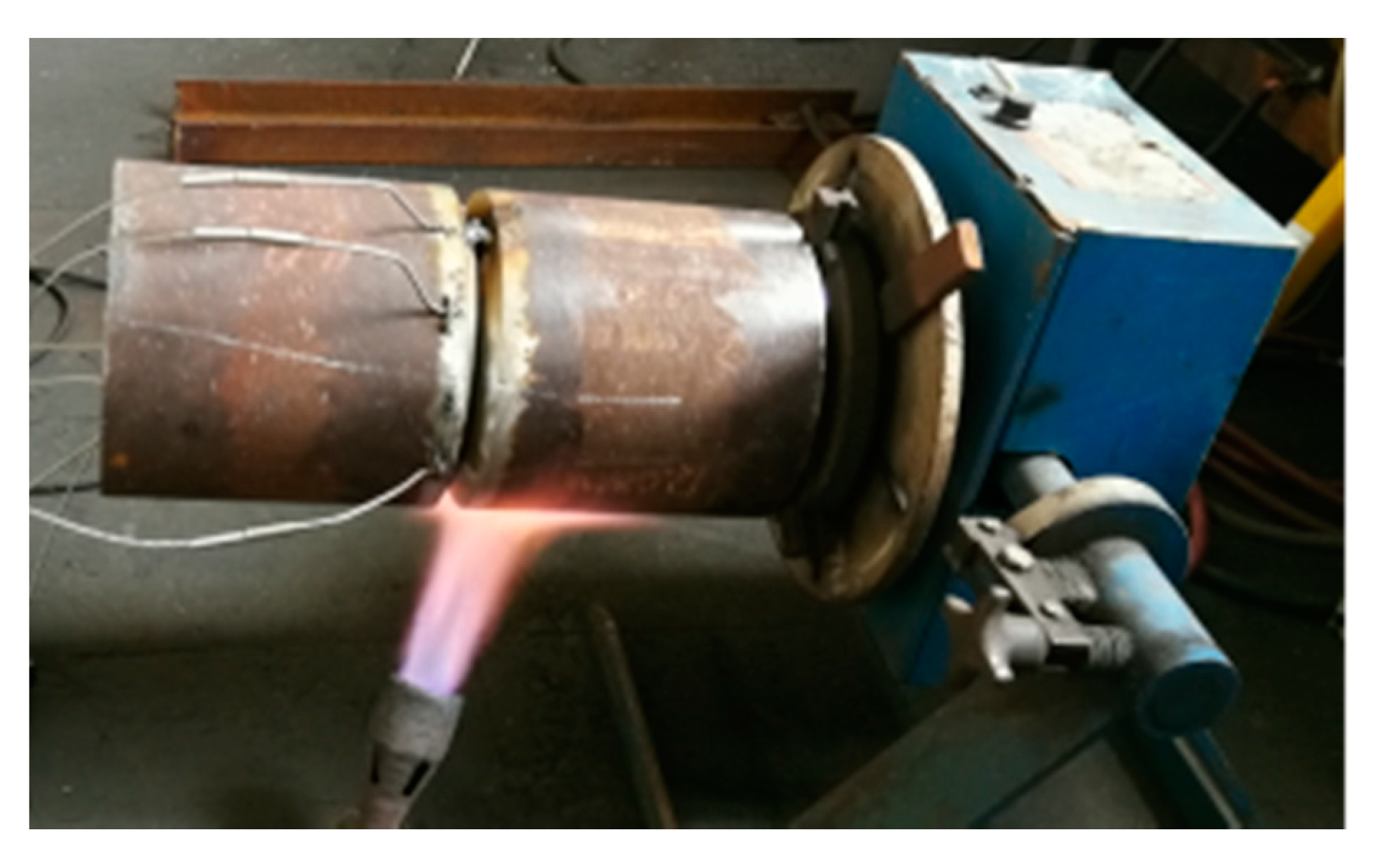
2.3. Post-Weld Heat Treatment Process

In order to investigate the distribution of welding residual stresses in the case of different post-weld heat treatment, thermal cycle curve shown in Figure 4 was used, i.e., DHT and tempering treatment were carried out successively. DHT was conducted at 350 °C for 2 h, while tempering was conducted based on the industry recommended 730 °C for 1.5 h [26].

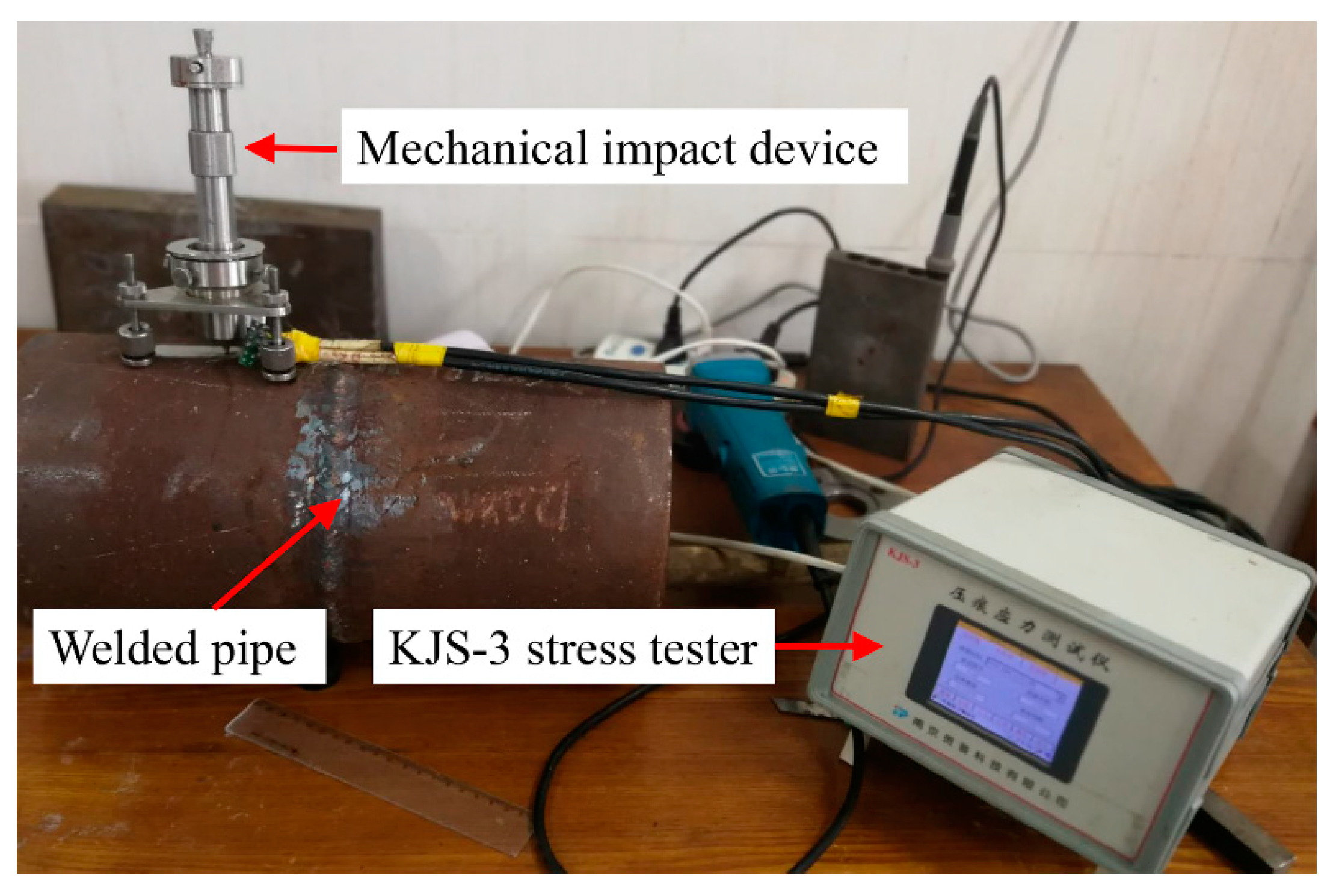
2.4. Residual Stress Measurement

Instrumented indentation test was conducted to measure the hoop stress and axial stress of different points along cross-weld path shown in Figure 3. This method has the advantage of almost non-destructive nature and convenience in operation [27]. The residual stress was measured by using the KJS-3 indentation stress tester illustrated in Figure 5. Firstly, the surface of the welded joint was mechanically polished. Then, the BA120-1BA-ZKY strain gauges were glued to the test points with professional adhesive and the stress tester was connected with the strain gauges. Thirdly, the impact indentation device was placed on the weldment (seen in Figure 5) and the spherical indenter was aligned with the strain gauge. Finally, the impact force was applied on the weldment by releasing the spring of the impact device.

3. Finite Element Simulation

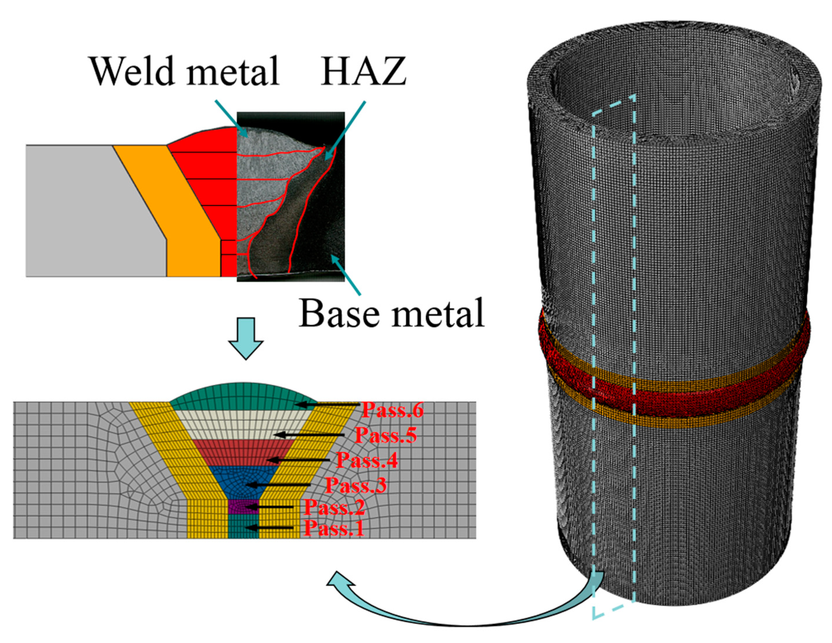
3.1. Finite Element Model

Three-dimensional finite element model was established and meshed according to actual geometrical size of the pipe, welding groove type and the multi-pass weld metal arrangement based on the microstructure observation, as shown in Figure 6. Totally, 519,381 nodes and 551,435 elements were meshed. DC3D8, DC3D6, and DC3D4 elements were used for thermal analysis, and C3D8R, C3D6, and C3D4 elements were used for structural analysis. In order to improve the calculation efficiency and ensure the calculation accuracy, the mesh size at the weld metal and the heat-affected zone (HAZ) was refined and the larger size mesh was adopted in the base metal.

3.2. Thermal Analysis

In order to save calculation time and cost. The volumetric heat source with uniform density was used in the thermal analysis. The heat flux of each weld pass can be obtained by the following equation [28,29,30]:
q i = η U i I i t w i t s V i
where qi (J/mm3) is the heat flux of the ith-pass weld; η is the arc efficiency factor, which was assumed as 0.7 for SMAW process; twi (s) is the total welding time of the ith-pass weld; ts (s) is the heating time used in the simulation; and Vi (mm3) is the volume of the ith-pass weld; Ui (V) is the welding voltage, and Ii (A) is the welding current. All the parameters are listed in Table 2.
The heat loss caused by heat convection can be calculated by the Newton cooling equation [31]:
q c = h c ( T s T a )
where qc (W/m2) is the heat flux across the welded surface due to convection; hc is the convective heat transfer coefficient, which was taken as 10 W/(m2·K); Ts (°C) is the current temperature on the welded surface; Ta is the ambient temperature, which was taken as 30 °C in the calculation.
The heat loss due to heat radiation was calculated by the Stefan–Boltzmann law [31]:
q r = ε σ [ ( T s + 273.15 ) 4 ( T a + 273.15 ) 4 ]
where qr (W/m2) is the heat flux across the welded surface due to radiation; ε is the emissivity, which was taken as 0.85 in the modeling; σ is the Stefan–Boltzmann constant, i.e., 5.67 × 10⁻⁸ W/(m2·K4).

3.3. Simulation of Welding and Post-Weld Heat Treatment

The same FE model used in the thermal analysis was employed in the residual stress analysis. A thermo-plastic sequential coupling FE program is developed to calculate weld residual stress by the ABAQUS finite element software (ABAQUS 6.14, Dassault SIMULA, Providence, RI, USA). Based on incremental plasticity theory, the total measurable strain can be partitioned into strain components as follows [32]:
ε = ε t h + ε e + ε p
The incremental form of the above equation can be expressed as
Δ ε = Δ ε t h + Δ ε e + Δ ε p
where εth, εe, and εp are thermal, elastic, and plastic strain, respectively. Stress-free stated can be achieved by setting the temperature-related material property, i.e., the corresponding elastic modulus at the liquid temperature is 0.001, which makes simulated result approaches stress-free state. The elastic strain was calculated according to the isotropic Hook’s law. The elastic modulus and Poisson’s ratio of the law are related to temperature. The plastic behavior was considered by Von Misses yield criterion. The work hardening was considered using the isotropic hardening rule. It is worth noting that Δε is only related with the constraint conditions (i.e., the geometric structure). For example, under fully restrained conditions, Δε = 0 must be maintained throughout the heating and cooling stages [33]. In this case, εth will increase during the heating process, i.e., εth = αΔT. Correspondingly, εe and εp must be changed to satisfy Equation (4). However, the variation of εe is limited, the maximum value of εe is σy/E, where σy and E are yield stress and Young’s modulus, respectively. Further heating results in no change in elastic strain. However, the increase in thermal strain with increasing temperature all goes to the equal amount of increase in compressive plastic strain εp. After cooling to room temperature, although the thermal strain disappears, there is still residual elastic strain and residual elastic strain, leading to residual stress and welding deformation. When post weld treatment is simulated, the calculated residual stress field is taken as the pre-stress condition of the post-weld heat treatment simulation. During PWHT, with the increase of temperature, the elastic modulus and yield strength of the material decrease accordingly. In other words, plastic strain will increase in turn. To effectively relieve residual stress, the amount of permanent tensile deformation that needs to be introduced into the welded joint should can be in the order of εy (=σy/E). This can be achieved through increase of plastic strain as mentioned above in uniform post-weld heat treatment (PWHT). This is a brief introduction, and the detailed information can be found in the literature [21,33]. The detailed thermo-physical properties of 12Cr1MoV steel used in the simulation are list in Table 3 [34]. It is worth noting that the matched filler metal, i.e., whose mechanical properties is similar to that of base metal, are used in this study. Hence, it is assumed that the thermo-physical properties of filler metal are in accordance with those of the base metal.
During the actual welding process, the pipe was clamped on a special fixture as shown in Figure 2. Therefore, in the simulation process, the inner surface of the pipe model was fixed and constrained according to the actual clamping mode.
When the heat treatment is simulated, the calculated welding stress field is taken as the pre-stress condition of the post-weld heat treatment simulation. During PWHT, with the increase of temperature, the elastic modulus and yield strength of the material decrease accordingly. When the residual stress is greater than the yield strength, the weldment produces plastic deformation, which releases the residual stress. The thermal load consistent with the thermal cycle curve as shown in Figure 4 is applied on the whole model.

4. Results and Discussion

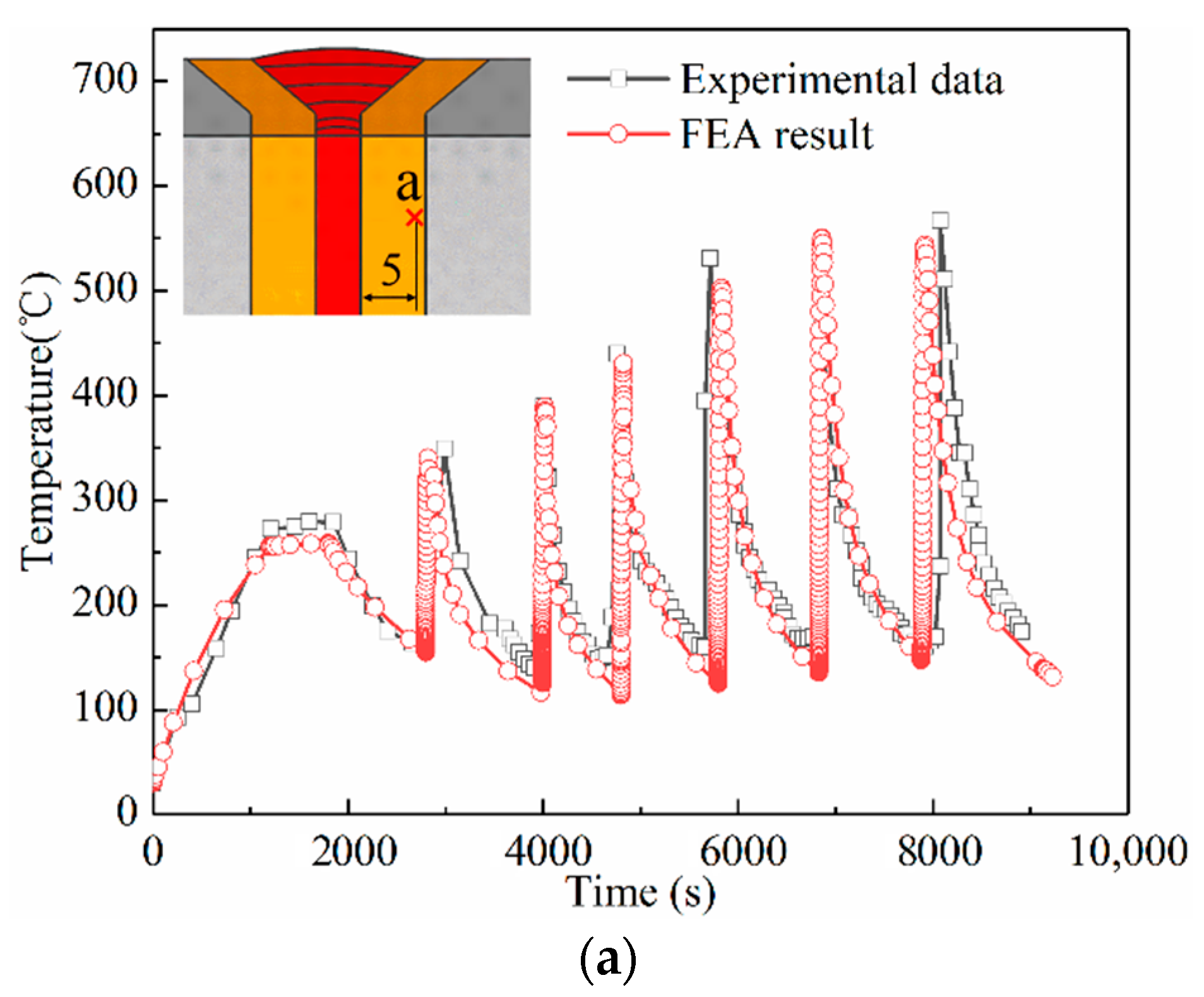
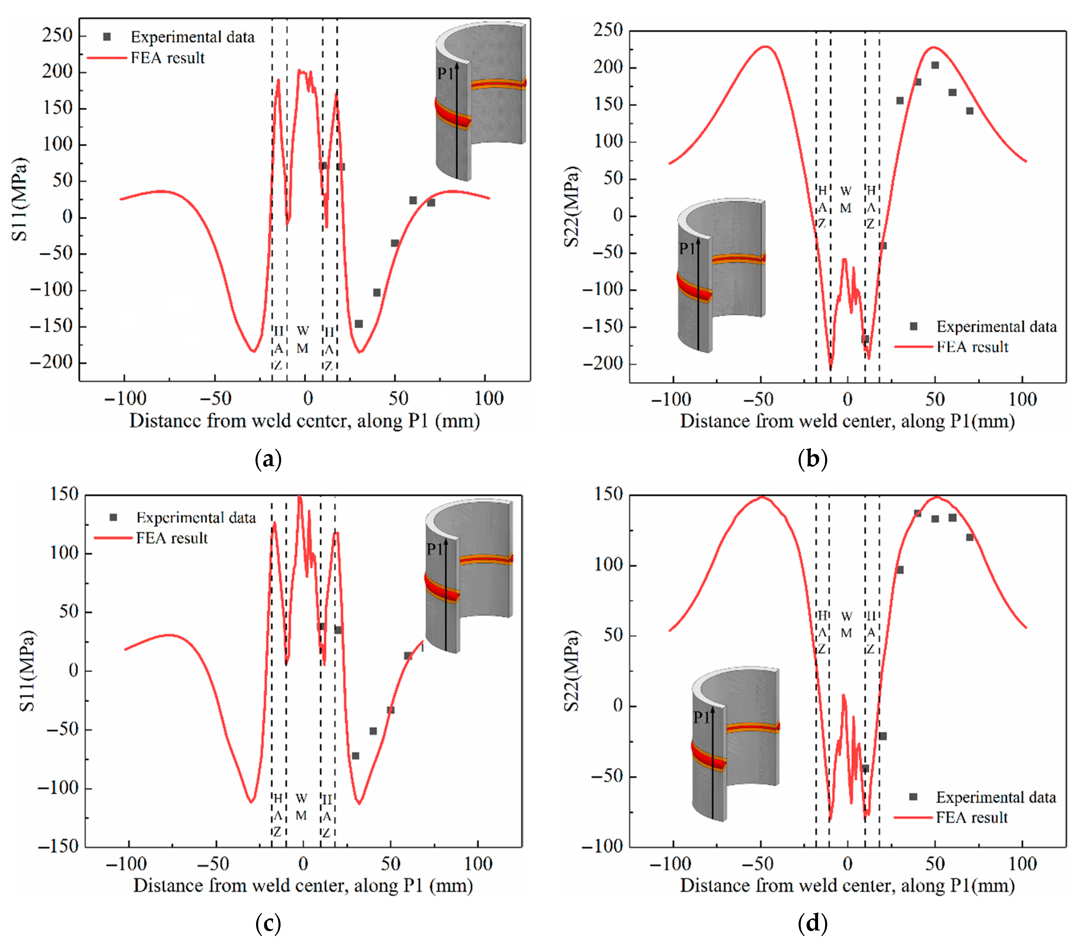
4.1. Verification of Simulation Results

Figure 7 shows the measured welding thermal curves of points marked as “a”, “b”, and “c” in Figure 3. It is found that the temperature increase dramatically to a peak value when the heat source is loaded. While, it decrease slowly as the heat source is removed. When the next pass is started, the phenomenon is repeated. It is worth noting that that peak temperature increase gradually with the increase of the number of thermal cycles. The order of different locations based on the peak temperature is: a > b > c, i.e., the closer to the weld center, the higher the peak temperature of each thermal cycle curve.
To verify the accuracy of the simulation results of welding temperature field, the measured thermal curves of the points marked as “a”, “b”, and “c” are compared with those obtained by simulation, respectively. The results are shown in Figure 8. It is clearly to see both peak temperature error and interlayer temperature error of points “a”, “b”, and “c” are less than 5%. Both heating rate and cooling rate are consistent with the experimental results. Therefore, it is proved the thermal simulation results are effective and reliable.
Both hoop stress S11 and axial stress S22 along outer surface P1 and inner surface P2 were measured by instrumented indentation method. There are seven points on each path. The detailed location is illustrated in Figure 9. Figure 10 shows the comparison between experimental results and simulation result of residual stress after different heat treatment. Overall, the simulation results are in good agreement with the measured value. It indicates that the simulation method could predict the residual stress precisely.

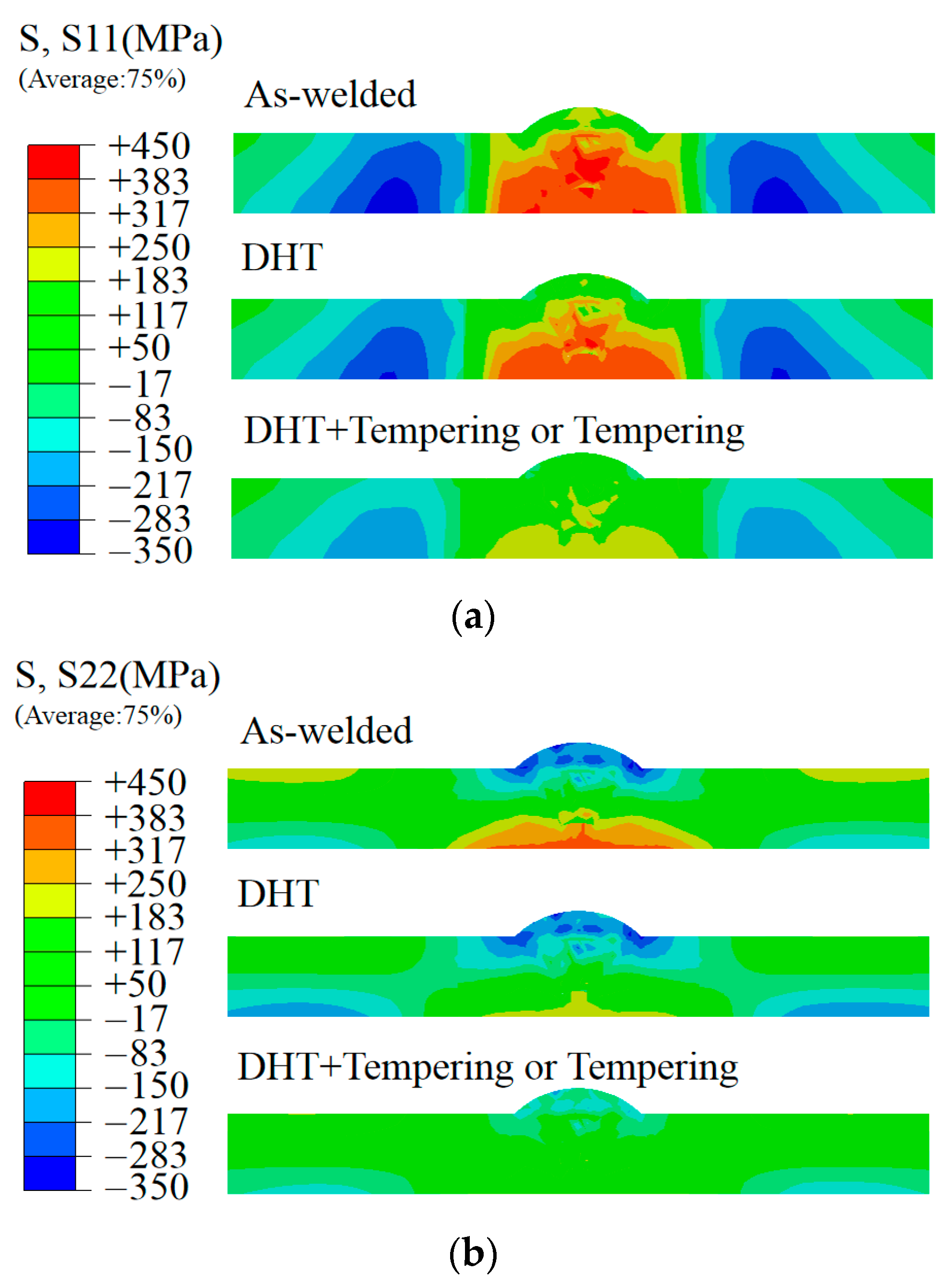
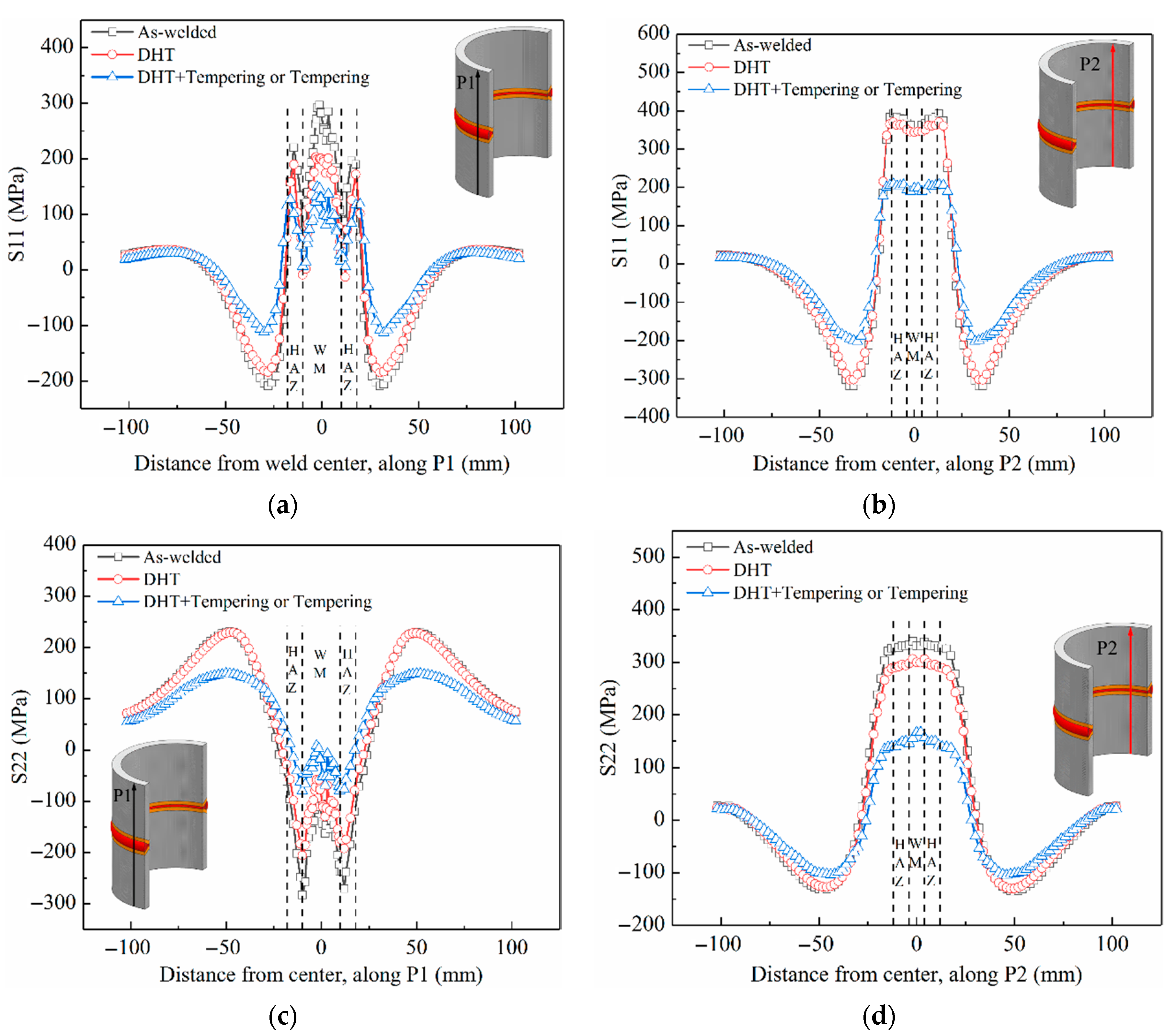
4.2. Comparison of Residual Stress Reduction Effects of Different Heat Treatment Processes

Generally, DHT is used to improve the welding quality by reducing hydrogen content in weld metal and heat affect zones. Hence, there is little attention paid to the residual stress reduction effects caused by DHT. However, profound understanding of residual stress evolution mechanism of DHT plays an important role in optimization of heat treatment process. In order to assess stress relief effect, residual stress distribution contours after welding without heat treatment, DHT, and tempering heat treatment are shown in Figure 11. As can be seen from Figure 11a, it shows that the hoop stress S11 distribution in longitudinal section of the pipe welded joint after DHT is similar to that after welding without heat treatment. It indicates that DHT has almost no effect on hoop stress S11 relief. However, DHT plays an evident influence on axial stress S22. Figure 11b shows that the maximum tensile axial stress S22 decreased obviously, while the DHT has no effect on residual compressive stress S22. This result is basically consistent with the measurement results of the residual stress value before and after the DHT by Xue et al. [17], but the finite element simulation cloud chart shows the residual stress release effect more intuitively. In comparison, tempering heat treatment has obvious effect on the amplitude and distribution of residual stress. It is worth noting that the stress distribution pattern after DHT + Tempering is same to that after Tempering without DHT. This means that DHT only required if immediate tempering heat treatment is not possible.
In the study of residual stress of 12Cr1MoVR tube welded joints with/without PWHT by Wang et al. [16], only the residual stress distribution of the weld and HAZ was studied, but the difference in the residual stress distribution between the inner and outer surfaces of the pipeline was not studied. Figure 12 compares the hoop stress S11 and the axial stress S22 after different heat treatment along outer surface P1 and inner surface P2, respectively. The S11 distribution along P1 is similar to that along P2, and the peak values were found at the weld (seen in Figure 12a,b). The maximum value of S11 on P1 and P2 are 315 MPa and 395 MPa, respectively. After DHT the maximum S11 decrease slightly, they are 230 MPa and 370 MPa, respectively. However, the maximum S11 are reduced to 135 MPa and 210 MPa, respectively. Hence, the order of different heat treatment based on the magnitude of stress relief is: Tempering heat treatment > DHT. For axial stress S22, although the stress distribution along outer surface P1 is different from that along inner surface P2, but there is no change in the residual stress reduction effects of different heat treatment processes.

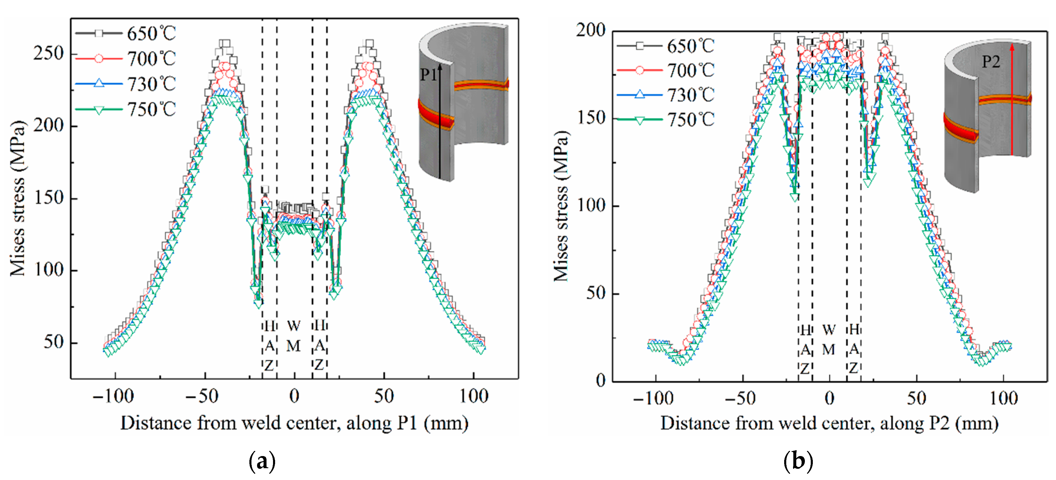
4.3. Optimization of Post-Weld Heat Treatment Process

As discussed in Section 4.3, the residual stress reduction effects of DHT + Tempering is same to that of Tempering. This means that DHT only required if immediate tempering heat treatment is not possible. Paddea et al. [20] and Tan et al. [35] only studied the residual stress reduction effect of a specified PWHT, but disregarded the influence of various parameters of PWHT on the release of residual stress. In order to realize optimization of post-weld heat treatment, the effect of peak temperature and holding time of tempering on stress relief is studied in detail. Figure 13a,b illustrate the Mises stress distribution along P1 and P2 at 650 °C, 700 °C, 730 °C, and 750 °C with holding time of 1.5 h, respectively. It is found that the higher the peak temperature, the better the effect of residual stress release. However, the stress release is mainly concentrated in the stress concentration area, and the magnitude of stress reduction is comparatively small. Figure 14a,b illustrate the Mises stress distribution along P1 and P2 at 730 °C with holding time of 1 h, 1.5 h, 2 h, and 2.5 h, respectively. Comparison of the simulation results show that the influence of the holding time is slight. Therefore, from the viewpoint of reduction of residual stress, it is recommended to increase the peak temperature and shorten the holding time.

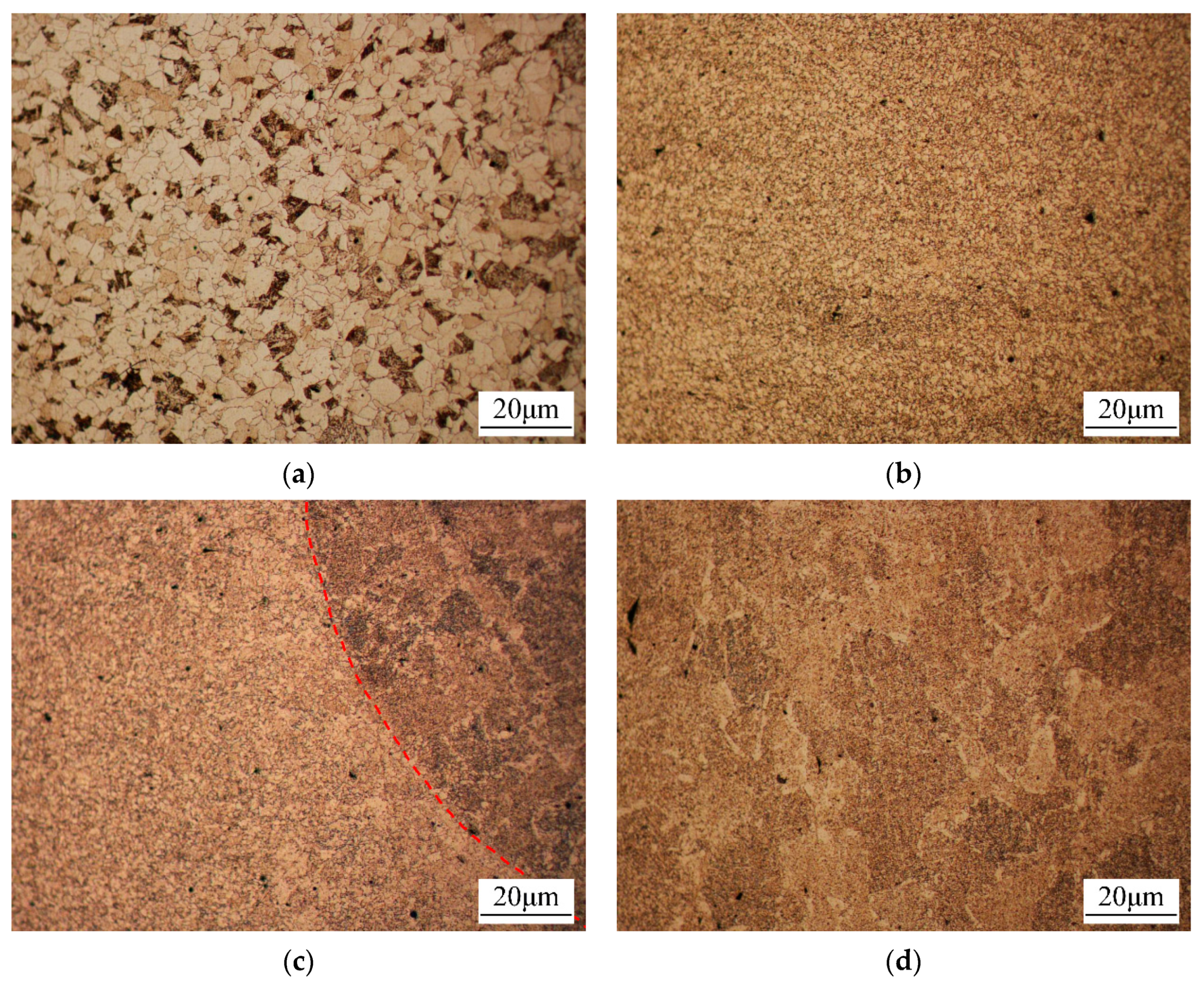
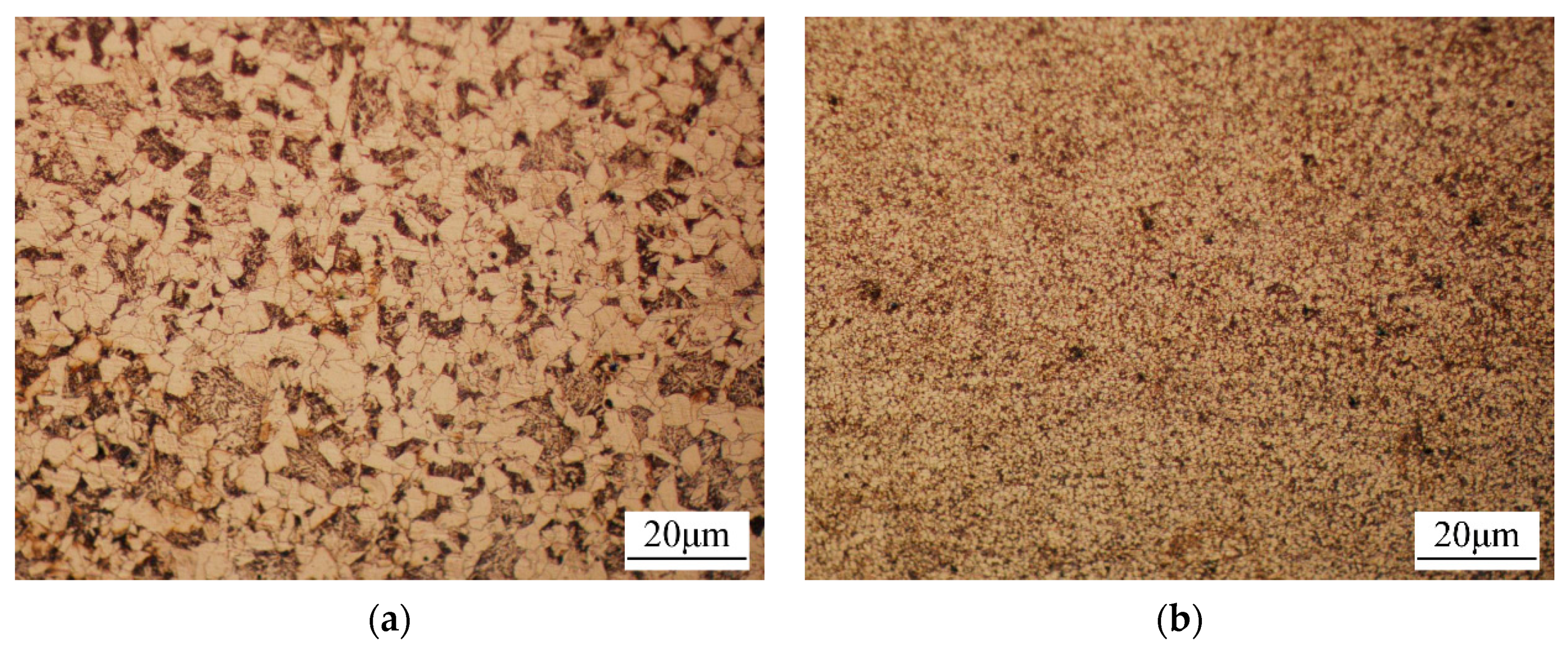
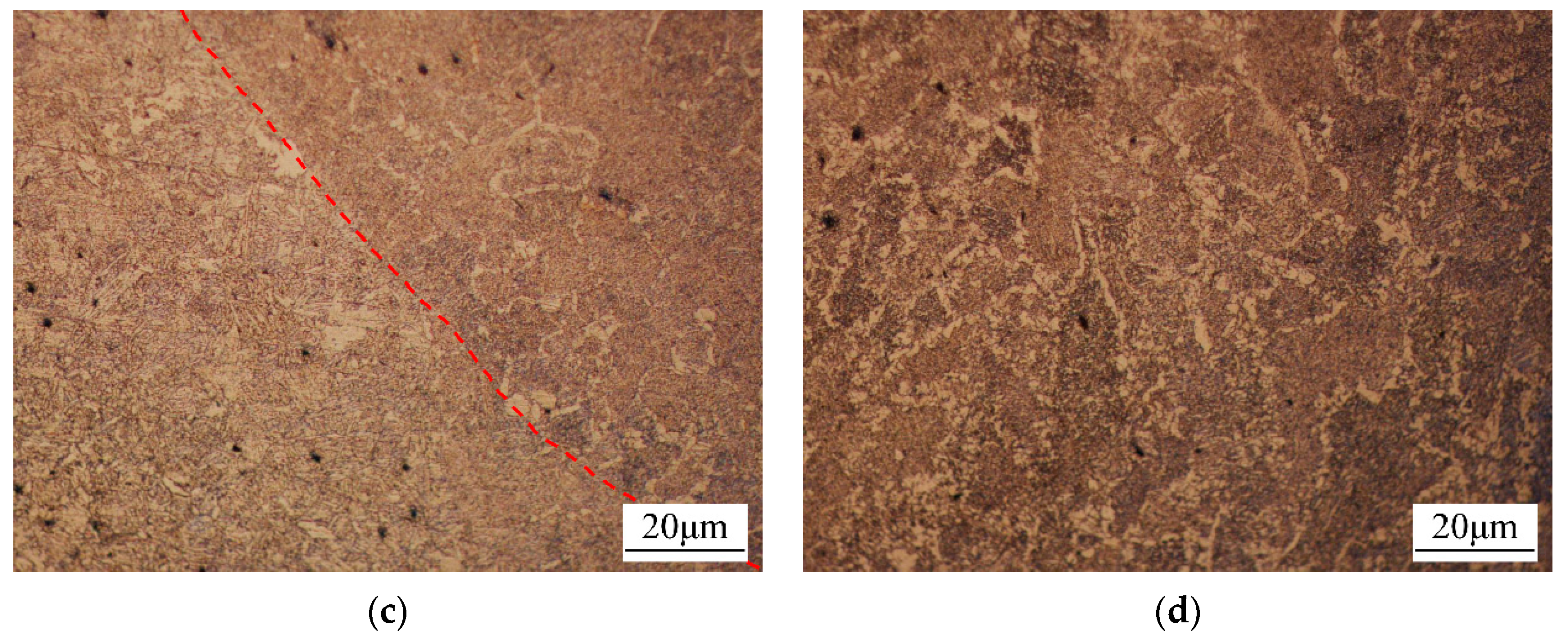
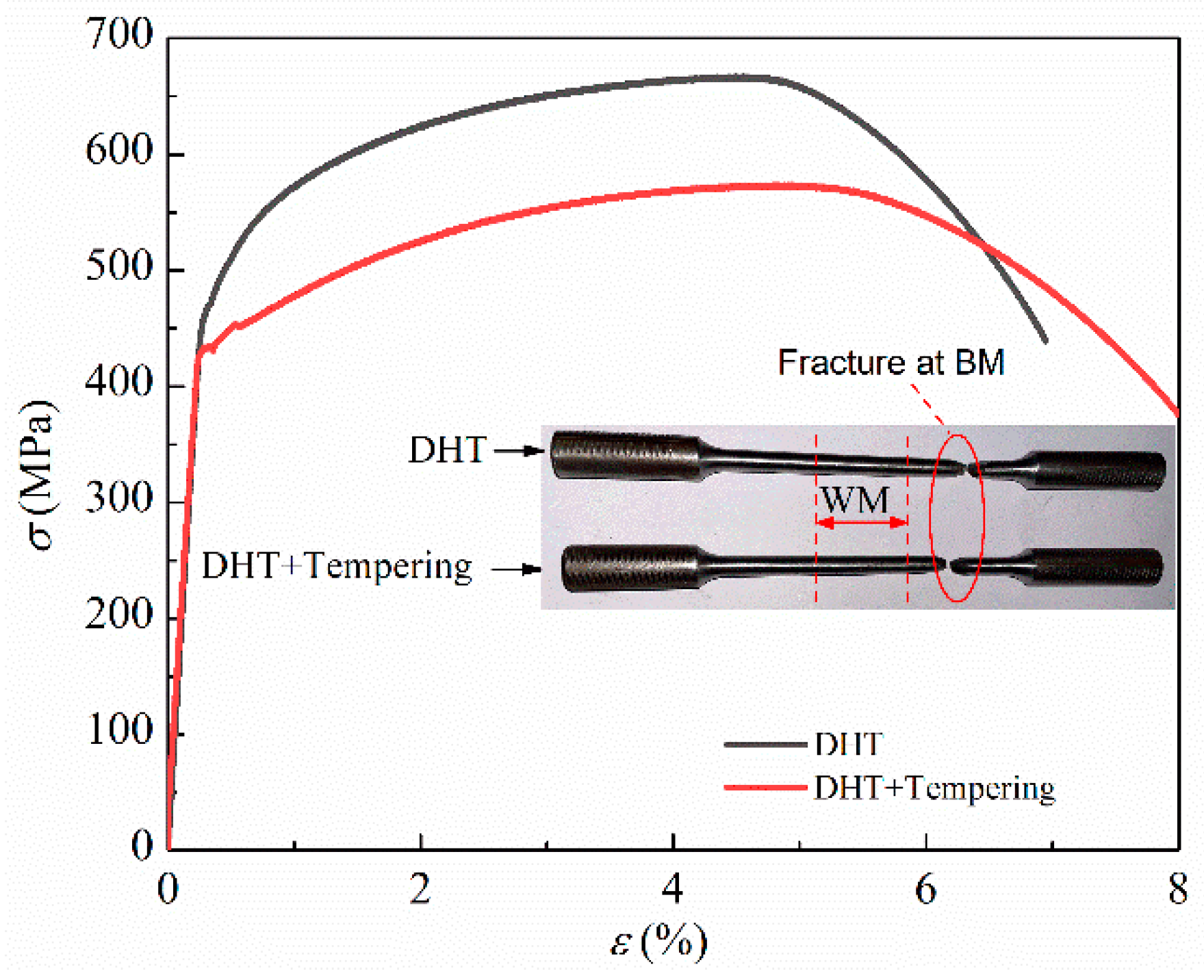
4.4. Influence of Post-Weld Heat Treatment on Microstructure and Tensile Property

The microstructures of 12Cr1MoV steel pipe weldment after DHT and tempering heat treatment are shown in Figure 15 and Figure 16, respectively. According to the microstructural morphology and grain size, the welded joint is divided into four subzones: base metal (BM), heat affected zone (HAZ), fusion zone and weld metal (WM).
Both BMs subjected to DHT and tempering heat treatment are composed of ferrite and pearlite. However, the amount of pearlite is obvious different. Microstructural observations revealed that the pearlite content in the BM with DHT (seen in Figure 15a) is higher than that with tempering heat treatment (seen in Figure 16a). The comparison between Figure 15b and Figure 16b show that the grain size of HAZ with DHT is smaller than that with tempering heat treatment. For WM with DHT, there are a large number of grain boundary ferrite, as shown in Figure 15c,d. However, the content of grain boundary ferrite of WM with tempering heat treatment decreased obviously, as shown in Figure 16c,d.
Micro-hardness of subzones in welded joints with different heat treatment are summarized in Table 4. For both welded joints, based on the micro-hardness, the order of different subzones is: WM > HAZ > BM. In addition, the overall micro-hardness of welded joint with DHT is higher than that with tempering heat treatment.
According to GB/T 228.1-2010 “Metallic materials-Tensile testing-Part 1: Method of test at room temperature” and GB/T 2651-2008 “Tensile test method on welded joints”, standard round bar specimens with diameter of 6 mm were used for tensile testing on a MTS 647 type universal testing machine. The tensile rate is 0.5 mm/min. The obtained tensile curves are shown in Figure 17. The yield strength and tensile strength of the welded joint with DHT are 487 MPa and 665 MPa, respectively. While those of the welded joint with tempering heat treatment decreased to 427 MPa and 574 MPa. However, all the tensile properties confirm to the requirement of GB 5310-2017 standard, i.e., the yield strength must exceed 255 MPa and the tensile strength must exceed 470 MPa. For both specimens, fracture occurred in BMs due to their lower strength.

5. Conclusions

The role of different post-weld heat treatment processes in the manufacturing process was studied experimentally and numerically. Conclusions are summarized as follows:
(1)
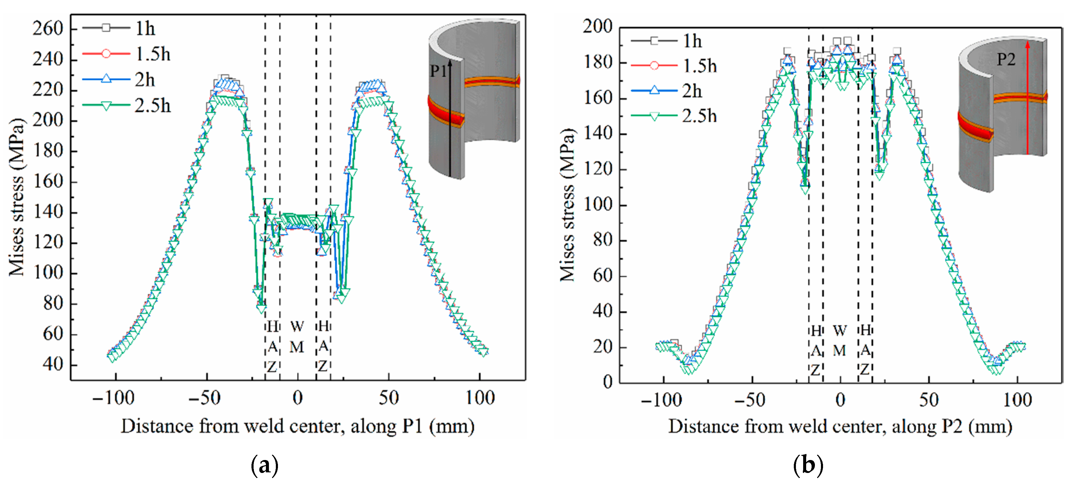
The residual stress relief effect of DHT is limited to the weld metal and heat-affected zone with reduction margin of about 10%. DHT has no effect on hoop stress S11, it only affects axial stress S22. Tempering heat treatment can reduce the residual stress including hoop stress S11 and axial stress S22 by 65%. After tempering heat treatment, the nonhomogeneous residual stress tend to be uniform.
(2)
The residual stress field after “DHT + tempering heat treatment” is same as that after tempering heat treatment alone. Therefore, it is not absolutely necessary to conduct DHT for as-welded joints. If the actual conditions permit, tempering treatment shall be carried out immediately after welding to save time and cost.
(3)
The higher the peak temperature of tempering treatment, the more obvious the residual stress reduced. However, a longer holding time has no obvious effect on the reduction of residual stress. If the main purpose of post-weld heat treatment is to reduce residual stress, the holding time can be appropriately shortened to obtain higher economic benefits.
(4)
For both welded joints, based on the micro-hardness, the order of different subzones is: WM > HAZ > BM. This is consistent with the observation of fracture occurred in BMs due to their lower strength. In addition, the micro-hardness of DHT welded joint is about 15–50 HV higher than that of tempering heat treatment. After tempering heat treatment, due to the decrease in pearlite content, the yield strength decreases from 487 MPa to 427 MPa and the tensile strength from 665 MPa to 574 MPa. While, the elongation increases with the decrease of grain boundary ferrite of WM.

Author Contributions

Conceptualization, X.H. and B.Y.; methodology Z.L.; software, Z.L.; validation, Z.Y., J.C., and M.S.; formal analysis, Z.L. and Y.L.; investigation, X.H. and B.Y.; resources, Z.Y.; data curation, Z.L.; writing—original draft preparation, X.H and Z.L.; writing—review and editing, B.Y. and J.C.; visualization, X.H.; supervision, B.Y.; project administration, B.Y.; funding acquisition, B.Y. All authors have read and agreed to the published version of the manuscript.

Funding

This research was funded by National Natural Science Foundation of China (Grants No.: 51805546), the Nature Science Foundation of Shandong Province (Grants No: ZR2019BEE050), the Fundamental Research Funds for the Central Universities (Grants No: 18CX02149A), UPC project (Grants No: YJ20170018).

Institutional Review Board Statement

Not applicable.

Informed Consent Statement

Not applicable.

Data Availability Statement

The data presented in this study are available in this article.

Conflicts of Interest

The authors declare no conflict of interest.

References

  1. Yang, B.; Xuan, F.Z. Nonhomogeneous microstructure related creep damage of the CrMoV multi-pass weld metal. Mater. Sci. Eng. A 2019, 763, 138122. [Google Scholar] [CrossRef]
  2. Yang, B.; Xuan, F.Z.; Chen, J.K. Evaluation of the microstructure related strength of CrMoV weldment by using the in-situ tensile test of miniature specimen. Mater. Sci. Eng. A 2018, 736, 193–201. [Google Scholar] [CrossRef]
  3. Yang, B.; Xuan, F.Z. Creep behavior of subzones in a CrMoV weldment characterized by the in-situ creep test with miniature specimens. Mater. Sci. Eng. A 2018, 723, 148–156. [Google Scholar] [CrossRef]
  4. Yang, B.; Xuan, F.Z.; Liu, X.P. Heterogeneous creep behavior of a CrMoV multi-pass weld metal. Mater. Sci. Eng. A 2017, 690, 6–15. [Google Scholar] [CrossRef]
  5. Jang, J.; Lee, B.W.; Ju, J.B.; Kwon, D.; Kim, W. Experimental analysis of the practical LBZ effects on the brittle fracture performance of cryogenic steel HAZs with respect to crack arrest toughness near fusion line. Eng. Fract. Mech. 2003, 70, 1245–1257. [Google Scholar] [CrossRef]
  6. Nitsche, A.; Allen, D.; Mayr, P. Damage assessment of creep affected weldments of a Grade 91 header component after long-term high temperature service. Weld World 2015, 59, 675–682. [Google Scholar] [CrossRef]
  7. Fabricius, A.; Jackson, P.S. Premature Grade 91 failures—Worldwide plant operational experiences. Eng. Fail. Anal. 2016, 66, 398–406. [Google Scholar] [CrossRef]
  8. Vinoth Kumar, M.; Balasubramanian, V.; Rajakumar, S.; Albert, S.K. Stress corrosion cracking behaviour of gas tungsten arc welded super austenitic stainless steel joints. Def. Technol. 2015, 11, 282–291. [Google Scholar] [CrossRef]
  9. Hu, J.; Liu, F.; Cheng, G.; Zhang, Z. Life prediction of steam generator tubing due to stress corrosion crack using Monte Carlo Simulation. Nucl. Eng. Des. 2011, 241, 4289–4298. [Google Scholar] [CrossRef]
  10. Ali, H.; Ma, L.; Ghadbeigi, H.; Mumtaz, K. In-situ residual stress reduction, martensitic decomposition and mechanical properties enhancement through high temperature powder bed pre-heating of Selective Laser Melted Ti6Al4V. Mater. Sci. Eng. A 2017, 695, 211–220. [Google Scholar] [CrossRef]
  11. Shi, X.; Zhang, Y.L.; Zhao, J.P.; Gou, R.B. Evaluation of welding residual stress based on temper bead welding technique. Adv. Mater. Res. 2011, 418–420, 1208–1212. [Google Scholar] [CrossRef]
  12. Fan, Z.; Du, J.; Zhang, Z.; Tian, J.; Ma, J.; Niu, K. Failure Mechanism of 12Cr1MoVG Tubes from Reheater in an Ultra-Supercritical Boiler. Mater. China 2019, 6, 614–619. [Google Scholar]
  13. Ronevich, J.A.; Song, E.J.; Feng, Z.; Wang, Y.; D’Elia, C.; Hill, M.R. Fatigue crack growth rates in high pressure hydrogen gas for multiple X100 pipeline welds accounting for crack location and residual stress. Eng. Fract. Mech. 2020, 228, 106846. [Google Scholar] [CrossRef]
  14. Olabi, A.G.; Hashmi, M.S.J. The effect of post-weld heat-treatment on mechanical-properties and residual-stresses mapping in welded structural steel. J. Mater. Process. Technol. 1995, 55, 117–122. [Google Scholar] [CrossRef]
  15. Samuel, E.I.; Choudhary, B.K.; Rao, K.B.S. Influence of post-weld heat treatment on tensile properties of modified 9Cr–1Mo ferritic steel base metal. Mater. Sci. Technol. 2007, 23, 992–999. [Google Scholar] [CrossRef]
  16. Wang, J.; Sun, J.; Yu, X.; Chen, G.; Fu, Q.; Gao, C.; Tang, W. Microstructures and mechanical properties of 12Cr1MoVG tube welded joints with/without post-weld heat treatment. J. Mater. Eng. Perform. 2017, 26, 4659–4666. [Google Scholar] [CrossRef]
  17. Xue, C.; Li, Z.; Zhang, J. Influence of Dehydrogenation Process after Welding on High Strength Steel Welding Residual Stress. Welded Pipe Tube 2013, 36, 22–25. [Google Scholar]
  18. Khalaj, G.; Pouraliakbar, H.; Jandaghi, M.R.; Gholami, A. Microalloyed steel welds by HF-ERW technique: Novel PWHT cycles, microstructure evolution and mechanical properties enhancement. Int. J. Press. Vessel. Pip. 2017, 152, 15–26. [Google Scholar] [CrossRef]
  19. Chen, Z.; Zhao, Y.; Zhao, J.; Wang, G.; Lu, L.; Liu, W. Analysis and Controlling for Cracks in Welded Joint of Thick Walled Steel 12Cr1MoVG. Proc. CSEE 2012, 32, 137–143. [Google Scholar]
  20. Paddea, S.; Francis, J.A.; Paradowska, A.M.; Bouchard, P.J.; Shibli, I.A. Residual stress distributions in a P91 steel-pipe girth weld before and after post weld heat treatment. Mater. Sci. Eng. A 2012, 534, 663–672. [Google Scholar] [CrossRef]
  21. Dong, P.; Song, S.; Zhang, J. Analysis of residual stress relief mechanisms in post-weld heat treatment. Int. J. Press. Vessel. Pip. 2014, 122, 6–14. [Google Scholar] [CrossRef]
  22. Qian, Y.; Zhao, J. Influences of local PWHT from different criteria at home and abroad on the residual stress of the under-matching welded joint. Int. J. Press. Vessel. Pip. 2017, 154, 11–16. [Google Scholar] [CrossRef]
  23. Liang, M.; Liu, S.; Song, L.; Zhao, Y. Effect of simulated stress-relieving heat treatment on microstructure and tensile properties of CLAM steel. Fusion Eng. Design 2019, 148, 111287. [Google Scholar] [CrossRef]
  24. Sterjovski, Z.; Carr, D.G.; Dunne, D.P. Effect of PWHT cycles on fatigue crack growth and toughness of quenched and tempered pressure vessel steels. Mater. Sci. Eng. A 2005, 391, 256–263. [Google Scholar] [CrossRef]
  25. Dey, H.C.; Albert, S.K.; Bhaduri, A.K.; Roy, G.G.; Balakrishnan, R.; Panneerselvi, S. Effect of post-weld heat treatment (PWHT) time and multiple PWHT on mechanical properties of multi-pass TIG weld joints of modified 9Cr-1Mo steel. Weld. World 2014, 58, 389–395. [Google Scholar] [CrossRef]
  26. Chen, L.; Xie, X.; Zhang, J.; Xia, C.; Gao, M.; Bai, Q. Performance evaluation of 12Cr1MoVG thick-wall pipe after multiple simulated post-weld heat treatment. Phys. Exam. Test 2019, 37, 23–28. [Google Scholar]
  27. Huang, C.; Li, H.; Luo, C.; Song, Y. Comparative study of blind hole method and indentation method in measuring residual stress of 2219 aluminum alloy arc-welded joint. Trans. China Weld. Inst. 2017, 38, 54–58, 131. [Google Scholar]
  28. Deng, D.; Kiyoshima, S.; Ogawa, K.; Yanagida, N.; Saito, K. Predicting welding residual stresses in a dissimilar metal girth welded pipe using 3D finite element model with a simplified heat source. Nucl. Eng. Des. 2011, 241, 46–54. [Google Scholar] [CrossRef]
  29. Deng, D.; Zhang, C.; Pu, X.; Liang, W. Influence of material model on prediction accuracy of welding residual stress in an austenitic stainless steel multi-pass butt-welded joint. J. Mater. Eng. Perform. 2017, 26, 1494–1505. [Google Scholar] [CrossRef]
  30. Deng, D.; Murakawa, H.; Liang, W. Numerical and experimental investigations on welding residual stress in multi-pass butt-welded austenitic stainless steel pipe. Comput. Mater. Sci. 2008, 42, 234–244. [Google Scholar] [CrossRef]
  31. Jiang, W.; Luo, Y.; Wang, B.Y.; Tu, S.T.; Gong, J.M. Residual stress reduction in the penetration nozzle weld joint by overlay welding. Mater. Des. 2014, 60, 443–450. [Google Scholar] [CrossRef]
  32. Jiang, W.; Chen, W.; Woo, W.; Tu, S.-T.; Zhang, X.-C.; Em, V. Effects of low-temperature transformation and transformation-induced plasticity on weld residual stresses: Numerical study and neutron diffraction measurement. Mater. Des. 2018, 147, 67–79. [Google Scholar] [CrossRef]
  33. Dong, P. On repair weld residual stress and significance to structural integrity. Welding World 2018, 62, 351–362. [Google Scholar] [CrossRef]
  34. Fu, K. Dissimilar Heat-Resistant Steel Tube Joint Welding Numerical Simulation. Master’s Thesis, Inner Mongol University, Hohhot, Inner Mongolia, China, 2015. [Google Scholar]
  35. Tan, L.; Zhang, J.; Zhuang, D.; Liu, C. Influences of lumped passes on welding residual stress of a thick-walled nuclear rotor steel pipe by multipass narrow gap welding. Nucl. Eng. Des. 2014, 273, 47–57. [Google Scholar] [CrossRef]
Figure 1. Schematic of welding groove and weld bead distribution.
Metals 11 00127 g001
Figure 2. Pre-heat treatment of 12Cr1MoV pipe welded joint.
Metals 11 00127 g002
Figure 3. Schematic of temperature and residual stress measurement points.
Metals 11 00127 g003
Figure 4. Thermal cycle curve of post-weld heat treatment.
Metals 11 00127 g004
Figure 5. Residual stress measurement by instrumented indentation test.
Metals 11 00127 g005
Figure 6. Finite element model and meshing.
Metals 11 00127 g006
Figure 7. Welding thermal cycle curves obtained from finite element analysis.
Metals 11 00127 g007
Figure 8. Comparison of the thermal cycle curves obtained from experiment and simulation at different points, a (a), b (b), and c (c). For the specific positions of a, b, and c points, refer to Figure 3.
Metals 11 00127 g008aMetals 11 00127 g008b
Figure 9. Illustration for paths used for residual stress analysis.
Metals 11 00127 g009
Figure 10. Comparison of the residual stress distribution along P1 path between experimental data and finite element analysis (FEA) result under different heat treatment conditions, S11 (a) and S22 (b) is the residual stress after dehydrogenation heat treatment (DHT); S11 (c) and S22 (d) is the residual stress after tempering heat treatment.
Metals 11 00127 g010
Figure 11. Comparison of residual stress distributions in condition of “as-welded”, “Dehydrogenation heat treatment” and “Tempering heat treatment”: (a) S11 and (b) S22.
Metals 11 00127 g011
Figure 12. Residual stress distributions at different paths of the welded joint: S11 along P1 path (a) and P2 path (b); S22 along P1 path (c) and P2 path (d).
Metals 11 00127 g012
Figure 13. Mises stress distributions at different peak temperature along P1 path (a) and P2 path (b).
Metals 11 00127 g013
Figure 14. Mises stress distributions with different holding time along P1 path (a) and P2 path (b).
Metals 11 00127 g014
Figure 15. Microstructures of the 12Cr1MoV welded joint after DHT: (a) Base metal, (b) HAZ, (c) fusion zone, (d) weld metal.
Metals 11 00127 g015aMetals 11 00127 g015b
Figure 16. Microstructures of the 12Cr1MoV welded joint after tempering heat treatment. (a) Base metal, (b) heat-affected zone (HAZ), (c) fusion zone, (d) weld metal.
Metals 11 00127 g016
Figure 17. Tensile stress (σ)-strain (ε) curves of the 12Cr1MoV steel welded joints after DHT or after tempering heat treatment.
Metals 11 00127 g017
Table 1. Chemical compositions of 12Cr1MoV steel pipe and R317 rods (wt. %).
MaterialCMnSiCrMoVSP
12Cr1MoV (BM)0.130.550.341.080.310.230.0180.017
R317 (rod)0.120.900.601.500.650.350.0200.020
Table 2. Technological parameters of the welding process.
Weld Bead NumberCurrent (A)Voltage (V)Welding Time (s)Cooling Time (s)Heat Input Value (kJ/mm)Filler Rod Diameter (mm)
Pass.11502210011000.4383.2
Pass.2120221207800.4183.2
Pass.3140251157850.5254.0
Pass.4140251309000.5834.0
Pass.5140251409100.6284.0
Pass.615025145Cool to 120 °C0.6754.0
Table 3. Thermo-physical properties of 12Cr1MoV steel used in the finite element model.
TemperatureSpecific HeatThermal ConductivityThermal Expansion CoefficientElastic ModulusPoisson RatioYield Stress
T (°C)C (J/Kg·K)λ (W/m·k)α (10−6/°C)E (Gpa)μσ (MPa)
2056045.210.82140.29393
10056945.213.02110.29374
20058645.213.42060.29-
30061142.713.61950.30308
40065340.513.81870.30285
50068237.714.21790.30266
60072935.514.41670.32251
700-33.414.6-0.32-
Table 4. Micro-hardness of subzones in welded joints with different heat treatment.
Heat TreatmentMicro-Hardness (HV)
Base Metal HAZWeld Metal
DHT200.6233.1274.9
DHT + Tempering183.8199.1226.7
Publisher’s Note: MDPI stays neutral with regard to jurisdictional claims in published maps and institutional affiliations.

