Review

A Review of Factors Affecting the Mechanical Properties of Maraging Steel 300 Fabricated via Laser Powder Bed Fusion

by
Barry Mooney
and
Kyriakos I. Kourousis
*
School of Engineering, University of Limerick, V94 T9PX Limerick, Ireland
*
Author to whom correspondence should be addressed.
Metals 2020, 10(9), 1273; https://doi.org/10.3390/met10091273
Submission received: 29 August 2020 / Revised: 19 September 2020 / Accepted: 20 September 2020 / Published: 22 September 2020
(This article belongs to the Section Additive Manufacturing)

Abstract

:
Maraging steel is an engineering alloy which has been widely employed in metal additive manufacturing. This paper examines manufacturing and post-processing factors affecting the properties of maraging steel fabricated via laser powder bed fusion (L-PBF). It covers the review of published research findings on how powder quality feedstock, processing parameters, laser scan strategy, build orientation and heat treatment can influence the microstructure, density and porosity, defects and residual stresses developed on L-PBF maraging steel, with a focus on the maraging steel 300 alloy. This review offers an evaluation of the resulting mechanical properties of the as-built and heat-treated maraging steel 300, with a focus on anisotropic characteristics. Possible directions for further research are also identified.

1. Introduction

Laser powder bed fusion (L-PBF) is a technology used in metal additive manufacturing (AM). Controlled by existing computer-aided design/manufacturing know-how, L-PBF systems drive a high-wattage laser energy source to selectively melt successive thin layers of metallic powder particles, which in turn produces high-density functional components, though the majority of these parts require additional finishing. A typical L-PBF process configuration is illustrated in Figure 1.
Since the mid-1990s, there have been major advancements in controlling the L-PBF technology’s underlying physics, and as a result, it became less complicated to implement in practice, and has become much more prevalent in recent years [1,2,3]. Metal L-PBF systems are well suited to serial production as they provide consistent and repeatable outputs and are capable of producing metallic components with the durability, quality, and precision suitable for industrial applications [4,5,6,7,8,9]. On account of the demand, the range of L-PBF processable materials has been expanding simultaneously, where so far, the compositions have closely followed that of standard alloys. The logic being, for structural applications, it is desirable that the AM parts do not deviate characteristically from those conventionally manufactured (CM) [9,10].
Maraging steels possess the mechanical properties which offer them engineering significance in applications where high strength, toughness, and ductility, at high hardness, and dimensional stability are required [11,12,13]. Maraging refers to martensitic microstructure, commonly found in steels, which can be strengthened/hardened through an ageing heat-treatment [14,15]. Maraging steel’s low-carbon soft martensitic matrix is mostly free from interstitial alloying elements, which rank it as an excellent candidate for synthesis by AM and welding [11,16,17,18]. It is maraging steel’s outstanding properties and conjunction with the L-PBF process’s shaping efficiency that give maraging steel 300 such appeal. The ideal situation is a stand-alone L-PBF technology that can produce parts exhibiting predictable, repeatable and reliable mechanical properties with implicit material characteristics. Comprehensive metallurgical evaluations and assessments of machine-specific behaviours are necessary in the pursuit of this goal. In the case of L-PBF maraging steel 300, however, the reality is that the AM system/feedstock suppliers provide very limited data on the output of the process in terms of the material’s performance. Moreover, the metallurgical observations in the literature are highly varied and the body of published research is currently inadequate to characterise material performance for engineering designs and products. The purpose of this review is to examine how the mechanical properties of the L-PBF maraging steel 300 are influenced by the: (a) AM process, namely powder and fabrication (focusing on processing parameters, laser scan strategy and build orientation) and (b) post-processing (focusing on heat treatment). The aspects covered in the review paper are illustrated in Figure 2.

2. Conventionally Manufactured Maraging Steel

2.1. Characteristics

The 18% Ni 300 grade maraging steel (referred for simplicity as maraging steel 300 in this paper), or slight modifications thereof, has been used widely in AM, and is retailed commercially in powder form under several aliases. Maraging steel 300 has already been recognised as a very important hardenable alloy in the mold and tooling industry. It was quickly identified that it might be especially well-qualified for use with contemporary metal AM process innovations when this technology emerged in the mid-1990s [2,19,20]. The processing advantages offered by AM have therefore given maraging steel 300 modern engineering significance for the fabrication of general mechanical components where high-resolution, high-precision, ultra-high-strength, toughness and ductility, and dimensional stability are required, such as aerospace parts and tooling [11,12,13,21].
Maraging steel’s exceptional strength and toughness are achieved by combining its binary Fe-Ni primary phase system with a fine dispersion of secondary phase alloying elements (Mo, Co, and Ti). Strengthening precipitates, which block the movement of dislocations/defects within the crystal lattice, are mobilised through a straightforward and relatively expeditious ageing heat-treatment [12,16,22,23]. The 300 designation represents the alloy’s yield strength (Rp0.2) in kilopound per square inch (ksi) units, whereas the maraging classification indicates a strong martensitic structure which can be improved significantly by a precipitation hardening heat-treatment (ageing) [15,24,25]. The maraging steel 300 was one of four strength grades (200, 250, 300, 350) developed by International Nickel (Inco) [12,14]. Inco initially developed four commercial MS grades (Table 1) which were tailored to cover a range of strength capabilities, with each strength level being optimised for toughness [24].
Maraging steel 300 is highly important with a large application scope in the aerospace/marine, defence and industrial sectors (e.g., in fabricating large welded artillery shells/vessels, precision load-bearing structures, and tooling mold and die) [12,18,24,26,27]. Considered ultra-high-strength steels, with processing advantages such as insensitivity to welding and ease of heat-treatment, maraging steels provide designers with materials that have high specific strength (yield strength, Rp0.2, to density), and fracture toughness (MPa. m ) for structural applications [12]. This is illustrated in the Ashby chart in Figure 3, where one can observe that maraging steels can be a competitive choice with titanium alloys.
High strength is achieved in these 18Ni maraging steel alloys by second-phase precipitation of intermetallic compounds rather than by carbide precipitation [28,29]. The presence of carbon must be as minimal as possible to avoid affecting the steel’s advantageous characteristics (strength-toughness combination, harden-ability, formability) [14]. Once these intermetallic compounds are present as a fine dispersion uniformly distributed throughout the softer Fe-Ni matrix, a condition of optimum strength can be obtained.

2.2. Heat Treatment

CM maraging steel 300 has traditionally achieved its strength by means of a two-stage heat-treatment [15,25], solution-annealing and isothermal ageing. The goal of the solution-anneal, whereby the alloy is heated and held in the fully austenitic phase (Typically 1 h at 815 °C), is to disperse the concentration of hardening elements, which have accumulated at grain boundaries, by fully dissolving them into a solid solution [18]. As the alloy cools rapidly to room temperature, the austenite transforms into extremely ductile, body-centered cubic (BCC) martensite [15]. This diffusionless transformation is easily achieved at low temperatures (135 °C) and cooling rates by virtue of the alloy’s high Ni content (18%) [14,15]. The outcome of the solution annealing process paves the way for the ensuing precipitation hardening response, which causes the second phase to precipitate locally.
Maraging steel producers supply the alloy in its solution annealed condition, which can be readily fabricated by conventional methods (CM). In fabrication, components exhibiting work-hardening can benefit from a repeated solution anneal, which re-homogenises the microstructure, suppresses anisotropy (i.e., caused by coldworking), and alleviates residual fabrication stresses. The material will once again display homogeneous mechanical properties, although naturally, this supplementary heat-treatment step incurs additional fabrication cost [15,18].
Strength is achieved when the dispersion of hardening particles precipitate locally to impede the motion of dislocations. These obstacles heighten the stress required for dislocation motion, hence enhancing the alloy’s strength and hardness. Furthermore, when good toughness is sought, maraging steel alloys are aged past their peak-hardness condition (overaged), where the decomposition of metastable martensite to austenite (or austenite reversion) takes place [30]. The ageing time (t) and temperature (T) parameters exert significant authority on the size development of precipitates [25].

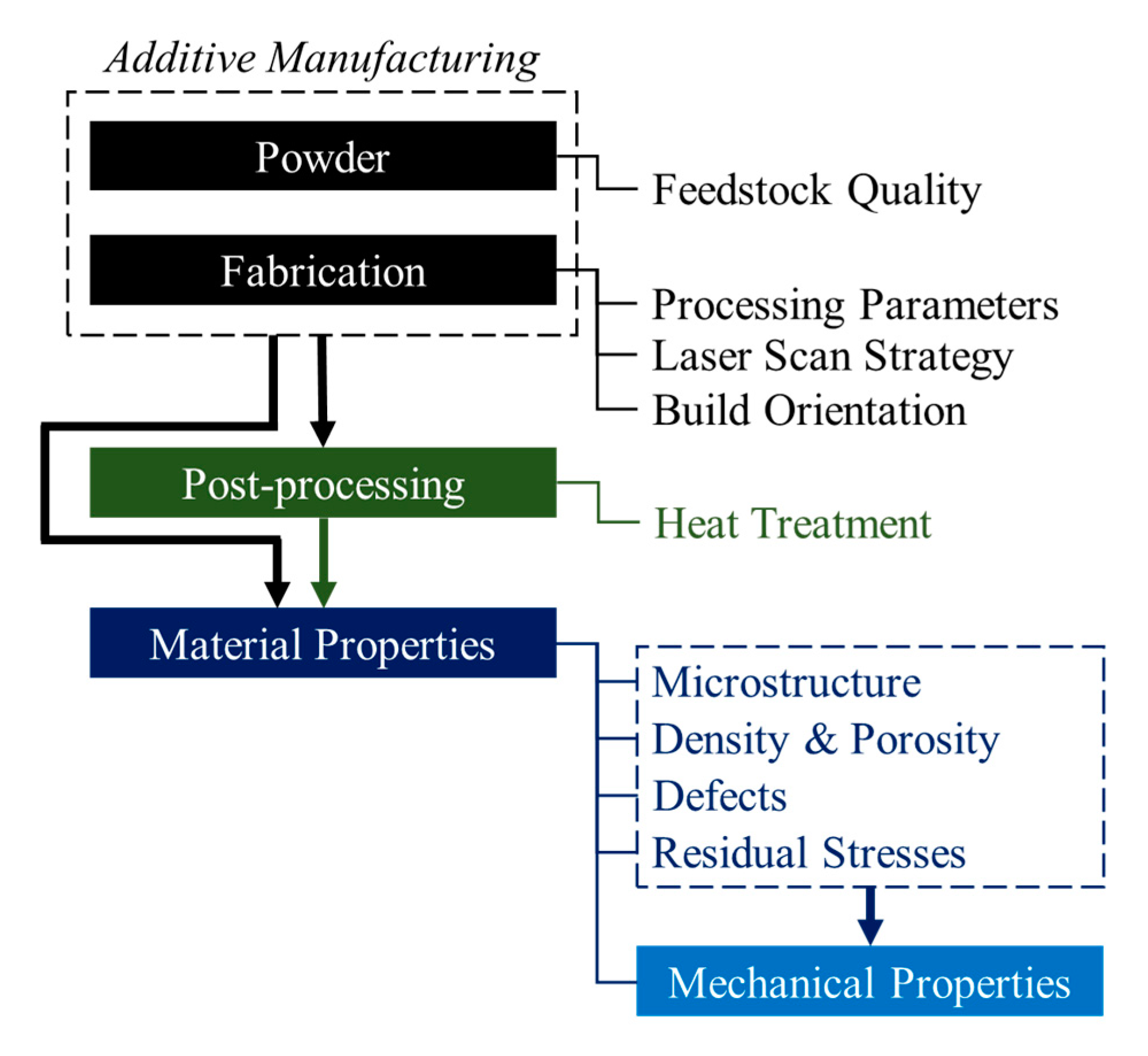
3. Factors Affecting Laser Powder Bed Fusion Built Part Properties

The L-PBF’s technology wider adoption by the industry relies on a foundational level of process control and an ability to regulate metallurgical outputs. As the technology continues to mature, more is expected of the functional parts produced, with special attention towards achieving metallurgical soundness by tackling the factors which influence mechanical performance [6]. Engineering design and manufacturing are influenced by material anisotropy, microstructural defects, etc., incurring additional costs to resolve these issues. Furthermore, unique attention for the produced parts in terms of extensive post-processing (i.e., surface finishing, heat treatment and non-destructive inspections) is necessary. Structure–critical metallic components produced by L-PBF systems are expected to display a high degree of isotropy, especially for high performance—fatigue critical applications.

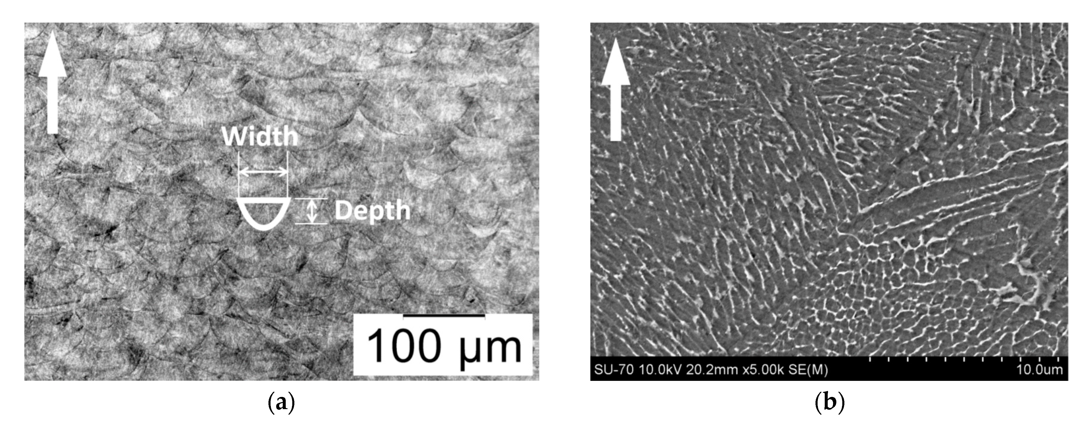
3.1. The Anisotropic Character of the Laser Powder Bed Fusion Process and Impact on Microstructure

Among issues identified is the dependence of mechanical properties on the build orientation, and the repeatability of mechanical properties outputs for products produced on different L-PBF equipment. The L-PBF build-process itself is inherently anisotropic. Uniaxial movement of the build plate, layer-wise powder deposition, planar movement of the heat-source (scan strategy), and the subsequent heat-transfer through pre-deposited layers, all promote orientation-dependent properties. When powerful laser scan strategies are employed to successively melt thin layers of fine powder particles, it provokes a distinct three-dimensional macrostructural pattern formation. At a deeper metallurgical level, the dynamics of heat-transfer within the melt-pool and surrounding material provokes specific microstructures. Depending on the particular alloy’s chemistry as well as the laser scan algorithm employed, this heat-transfer can cause directionality of crystal growth (fibre texture) and non-random crystalline orientation effects (crystallographic texture) [31,32,33,34,35]. Cyclic high-temperatures and rapid melt-pool cooling rates, along with the magnitude and direction of heat flow, continually change grain-boundary location within and between build layers. This thermal handling guides the formation of the AM microstructure evolution, crystalline orientation, and fibrous alignment. Both fibrous and crystallographic textures have been correlated to mechanical property anisotropy in a range of AM materials (e.g., IN738LC alloy, Hastelloy X) [32,34].
Columnar grains have been reported in several studies, with their axis orientated parallel to the direction of build and concurrent with the direction of maximum heat-flow [3,31,36]. The preferential growth of columnar grains for a given build layer can be broken up by rotating the laser scan direction (e.g., 90°) for subsequent layers as demonstrated by AlMangour et al. [37]. This approach led to decreased texture and reduced mechanical property anisotropy in TiB2/316 L stainless steel nanocomposites. Similarly, Bhardwaj et al. [38] recently demonstrated how the laser scan direction has a strong influence on the crystallographic texture and mechanical properties in EOS maraging steel 300 (codified as MS1), showing that the texture depends on the adopted scan strategy.

3.2. Impact on Built Part Properties

The state of anisotropy in the as-built metal is further exacerbated by ancillary process defects, such as residual stresses, and porosity. In addition, the L-PBF build conditions (environmental conditions, processing parameters, and quality of raw materials) are known to influence part performance and can amplify/ exaggerate the condition of anisotropy and affect repeatability. Part density is compromised by imperfections such as regions of un-melted powder, and the presence of voids/porosity and inclusions [39,40,41]. Porosity reduces the fabricated component’s effective cross-sectional area and can act as stress raisers and potential loci for fracture initiation [5,39]. Lower fatigue strengths have been reported for L-PBF components due to these defects [42]. Furthermore, the correct use of support structures during the build process is essential for controlling the deformation of parts from thermal residual stresses which are the unavoidable consequence of the mandatory high melt-pool temperatures and rapid cooling rates.
Residual stresses in AM-produced alloys are the unfortunate and unavoidable consequence of the short and severe laser-powder interaction times and rapid melt-pool cooling rates [43]. Residual stresses can lead to dimensional instability either during the build, or during secondary machining operations (e.g., when the parts are removed from the build plate). The residual stress distribution through the material also plays a significant role in the component’s directional mechanical properties. The severity of these process induced imperfections has somewhat abated in recent years, with the continued harmonisation of processing conditions, and the improved quality of raw materials [4,31]. Nonetheless, the art has not been completely mastered, meaning the defects that persist are more than enough to impact the mechanical performance and intensify anisotropy in L-PBF fabricated metals.
The multitude of fabrication variables (e.g., laser power, scan speed, layer thickness) which require optimisation in order to ensure sound metallurgical bonding whilst curtailing process defects, signify the level of control complexity that industrial practitioners must grapple with. Some L-PBF system providers ameliorate the cause by providing factory default, undisclosed, and pre-optimised sets of parameters for specific material and machine combinations. These support reliable mechanical properties and bolsters a repeatable industry level of quality making it possible to directly fabricate near fully dense components that exhibit the mechanical functionality necessary for heavy-duty tasks [44].

4. The Laser Powder Bed Fusion Maraging Steel

4.1. Microstructure

The typical low-magnification microstructure of maraging steel 300 has a complex appearance, with bundled interconnections of fan-shaped solidification cells between molten lines [17,45]. An example of the sectioned microstructure is shown in Figure 4. The particular development/detail (i.e., melt-pool width and depth) is subject to the L-PBF processing parameters employed (e.g., the layer thickness, scan strategy, scan spacing, speed and laser power). Nonetheless, several maraging steel 300 studies [17,45,46,47] employing alternative L-PBF systems and process parameter settings report very similar microstructures. In these studies, the melt-pools were observed to range in width (75–100 μm) and depth (40–50 μm), shown in Figure 4a, which is reflective of the applied laser spot-size, energy and layer-thickness. Variations in the reported AM systems’ laser input energy (i.e., ranging between 105–400 W), laser scan strategies (e.g., the scan rotation angle between successive layers), and the use of pulsed versus continuous line scan, were also observed across these studies. These general observations serve to demonstrate how the AM processing procedure is not a standardised practice, and the methods by which it is administered, along with the metallurgical results achieved, are subject to variation between producers.
A higher magnification image revealing the formation of a microstructure (fused/re-solidified zones) of very fine solidification cells is shown in Figure 4b. These cellular martensite bundles comprise a compact arrangement of fine, coarse, and dendrite cell formations with sub-micron intercellular spacing, and grow epitaxially across laser-tracks and build-layers [28,29,40,45,46,47]. Assisted by rapid melt-pool cooling rates (circa 103 to 108 K/s), the evolution mechanisms of these cells relate to the melt-region thermal flux direction which changes for successive layers whereby the cells orientate themselves concurrent with the direction of heat-flow/removal. A theoretical explanation of their formation is presented in a recent study by Tan et al. [48]. This characteristic cellular structure, unique to the powder processing method, is believed to be a major contributor to the strength difference between as-built AM versus the solution-annealed CM alloy, which in contrast does not display retained austenite in its microstructure, and exhibits random parent grains, each containing coarse and disordered packets of parallel lath-martensite [13,16,47,49,50].
As shown in Figure 4, retained austenite is easily distinguishable in the high magnification microstructure where it presents as the bright phase which aggregates at cell boundaries. It arises in the as-built alloy from an uncompleted transformation into martensite during the rapid cooling/solidification. The existence of these microscopic segregated solute-rich regions not only softens the as-built alloy, but also augments further austenite reversion during the elevated temperature precipitation heat-treatment cycle [17,40,51,52,53].
Accordingly, the importance of appropriate L-PBF processing variables is evident since these will govern the volume of retained austenite in the as-built microstructure, and ultimately the part performance. Studies that performed quantitative phase analysis [17,46,51,52] have confirmed a significant amount of retained austenite in the as-built metal, however, are at variance with regards to the percentage volume present. Jägle et al. [52]—who used high resolution electron backscatter diffraction (EBSD) scans—estimated a volume fraction of 8.5% ± 3.56%, whereas Casati et al. [17], Kempen et al. [51], Suryawanshi et al. [46], Yin et al. [54], and Tan et al. [48] performing Reitveld refinements measured 11.38%, 5.8%, 10%, 10.3% and 1.6% respectfully.
The observed variability in the literature may indeed be the direct result of the individual fabrication parameters and scan strategies and/or due to material characterisation diligence. In their study, Bhardwaj et al. [38] quantified the effect of two alternative laser scan strategies on the volume of as-built retained austenite and found that the scan strategy indeed impacts on the quantity of this phase, and thus the alloy’s as-built tensile properties (discussed further in the sequel). The harmful effect of this austenite phase, which limits the as-built alloy’s strengthening capacity, can be greatly diminished by holding the laser heat-input to a minimum, in conjunction with the use of appropriate laser scan strategies.
When comparing the AM material against its CM counterpart Jägle et al. [16] found no observable difference between the precipitate chemistry, formation kinetics, morphology, or size. Despite their vastly different processing routes (CP versus AM), precipitates form in the very same way, although the materials exhibit significantly different characteristics with respect to the grain-morphology and size, the texture, and the presence of retained austenite. The alloy’s processing history can be held exclusively responsible hence. In an early study by Stanford et al. [13] the authors claim that precipitation took place in EOS MS1, during the build process, as revealed by their microstructural evaluation. Particles of ~20–100 nm in size were observed via Scanning Electron Microscopy (SEM), and the material exhibited a good degree of hardness in the as-built condition (387 Vickers Hardness (HV), 39–40 Rockwell C Hardness (HRC)). In stark contrast, Jägle et al. [29] reported no evidence of early precipitation or nucleation of solutes in the as-built material despite the alloy’s propensity to develop precipitates, and despite AM’s unique thermal profile (intrinsic heat-treatment). This view is shared by Mutua et al. [49], who declare that the high solidification cooling rates prohibit the formation of precipitates. In more detailed follow-up examinations, Jägle et al. [16] state that early stages of precipitation are limited to Ti-Ti clustering which constitutes the early formation of Ni3Ti precipitates. When investigating the size and morphology of precipitates in aged material Jägle et al. [29] found that the particles ranged in size from diameter ~2–11 nm depending on their chemistry. Separately, Suryawanshi et al. [46] found the average precipitate size to be ~40 nm in length and ~5 nm in width. These conclusions put Stanford’s observations into question. The works conducted by Jägle are considered to have a greater technical footing as they employed more capable L-PBF equipment, and more appropriate characterisation techniques in their assessments.
The discrepancies between studies, however, is a testament to the level of variation that exists between independent researchers and producers. The selection of equipment, processing parameters, and characterisation techniques can provide vastly contrasting results between studies.

4.2. Factors Affecting Material Properties

4.2.1. Powder

An area of primary research is focused on L-PBF system parameter optimisation with the prevailing goal of eliminating microstructural defects such as porosity, un-fused particles, and micro-cracking. Moreover, incorrect combinations of process parameters have an influence on the part’s distortion and its final geometrical accuracy. While the user can impose certain authority over the system’s control parameters and performance towards this goal, the feedstock quality (chemical composition, size and morphology) is more intractable, and plays an important role in the final quality and properties of the fabricated part. The chemical composition specification ranges covering the main commercially available maraging steel 300 powders (including EOS MS1, Concept Laser CL50WS and Renishaw M300) [55,56,57,58,59,60,61,62], which are typically controlled by L-PBF equipment manufacturers, are presented in Table 2.
Individual suppliers work within these specification limits for their specific powder blend. The defined chemical specification of a given powder variant is critical towards the achievable properties of the finished part, however, these specifications are often difficult to achieve in production because the powders tend to vary within specification (e.g., through regulation of gas and vacuum parameters during atomization). Therefore, a degree of supplier and batch variability is inevitable [63,64]. Slight alterations to the powder’s chemistry can have major implications on the produced parts as discussed in a case study by feedstock supplier LPW Technology [63]. The discovery of cracking in bulk L-PBF maraging steel 300 was traced back to the presence of residual chemical elements—in particular Silicon, Manganese and Boron—which were not deliberately added to the alloy but were present in raw material despite the powder falling within specification for the main comprising elements. This highlights the alloy’s sensitivity to upstream contamination and signifies the importance of sourcing quality assured products from reputable suppliers who can meet narrow chemical specification requirements and mitigate against residual element contamination.
As with the powder’s chemistry, subtle alterations to its morphology (size and shape) can exert significant control over the L-PBF build quality, particularly, the as-built surface roughness and relative density of the parts. The powder granule shape and size distribution determine the achievable layer-wise packing density, flowability and inter-particle sintering kinetics during fabrication [65], yet very few L-PBF maraging steel 300 researchers [48,66,67,68,69] have performed particle analysis on the starting material, thus making it difficult to correlate observed microstructural defects and mechanical properties variations with the feedstock characteristics.
In these studies, unimodal distributions of spherically shaped granules with size range 10–70 μm, and central tendency of 35–40 μm, have been generally acknowledged. When a batch of powder is cycled through multiple AM builds, the feedstock experiences a steady gain in Nitrogen and Oxygen concentrations [70], as well as a shift towards larger and agglomerated powder granules which tend to get pushed cross-platform into the system’s collection chamber during recoating. Contrastingly, smaller spherical granules, which permit high packing efficiencies, are more readily consumed by the process. These symptoms of powder recycling will impede flow behaviour due to inter-particle friction during the recoating process, lead to reduced packing efficiencies, and effect the feedstock’s interaction with the laser beam.
Together these factors will ultimately lower the AM part’s build quality (i.e., surface roughness and relative density) [65,71]. Irregular shaped microstructural defects/pores are indicative of powder packing deficiencies, whereas the formation of spherical pores pertains to melt-pool gas entrapment. So far, only one early study by Hoeges et al. [72] has presented findings on the influence of maraging steel 300 feedstock on the produced metal. The study deals with a comparison between gas and water atomized maraging steel 300 powders, and their influence on the properties of L-PBF test-coupons. Despite only slight differences in the powder morphologies, it was necessary to modify the L-PBF processing parameters for each of these powder variants in order to achieve similar relative densities in the produced parts.
To date, however, no study has examined the role of particle morphology on the achievable surface roughness, relative density and mechanical properties of maraging steel 300 by holding constant the L-PBF processing parameters. Perhaps the ongoing development of new in situ techniques for L-PBF process monitoring/diagnostics, i.e., [73,74,75], will allow enhanced process reliability by compensating for feedstock variations in real-time fabrication, and ultimately facilitate the production of components exhibiting enhanced material performance.

4.2.2. Processing Parameters

Several maraging steel 300 studies have identified the optimum processing parameters as those which provide part relative density >99% [39,40,41,46,47,76]. According to powder feedstock supplier LPW, a relative density of >99.9% is considered the benchmark for near fully dense builds [63]. Experimental results published by Koutney et al. [67] showed that an increase in the laser energy density during AM processing (i.e., from 53.6–65.5 J/mm3) can lead to enhanced relative density (99.1–99.9%) and superior mechanical properties (e.g., 16% increase in Elasticity Modulus (E), 3% greater yield strength (Rp0.2) and 26% increased ductility) in as-built maraging steel 300. Energy density (Ed) is a function of laser power (P), scan speed (v), pitch (scan spacing) (h), and layer-thickness (lt) as described by Equation (1) [49,77]:
Ed = P/vhlt
Through a Design of Experiments (DOE) approach, Casalino et al. [77], Campanelli et al. [78], and Mutua et al. [49] lay the groundwork for maximising relative density while signalling the significance of Ed by varying factors P and v, and monitoring the alloy’s resulting mean-response in terms of density, hardness, tensile strength, and ductility measurements. The mechanical properties were highly variable due to the effects of Ed on the resulting relative density which ranged in these studies from 90.9–99.9%. In their work, Mutua et al. [49] provide a graphical process window/schema obtained from their experimental results. The schema relates these influential parameters (P, v, Ed) and clearly identifies a suitable L-PBF process window for maraging steel 300 fabrication, i.e., regions in which the relationship between these input variables corresponds to alterations in the alloy’s relative density, microstructure, and hence the mechanical properties. The authors also showed that excessively high Ed will lead to porosity, thus, a reduction in the alloy’s relative density. The spherically shaped pores observed in this condition were caused by gas entrapment within molten pools. Similarly, Suryawanshi et al. [46] suggest that a sub-optimal combination of process settings, namely laser power (P) and/or lower scan-speed (v) may have been responsible for the presence of small spherically shaped pores in their fabricated test specimens. The same authors present contradictory porosity quantifications for alternative evaluation techniques: the Archimedes method (0.5%), and Image Analysis Method (0.7–1.1%). In their reported mechanical properties, an underperformance in terms of the alloy’s as-built strength can be observed. Furthermore, the aged (5 h at 480 °C) tensile ductility properties were approximately 40% lower than the guide-values outlined in their material supplier’s datasheet [57]. As highlighted earlier, these metallurgical defects can act as stress raisers and potential loci for fracture initiation causing the alloy to fail prematurely. Moreover, the state of anisotropy can be exacerbated by ancillary process defects, such as residual stresses, and porosity, and a number of researchers have investigated the effect of L-PBF processing parameters to improve the build quality of maraging steel 300 [49,77,78].

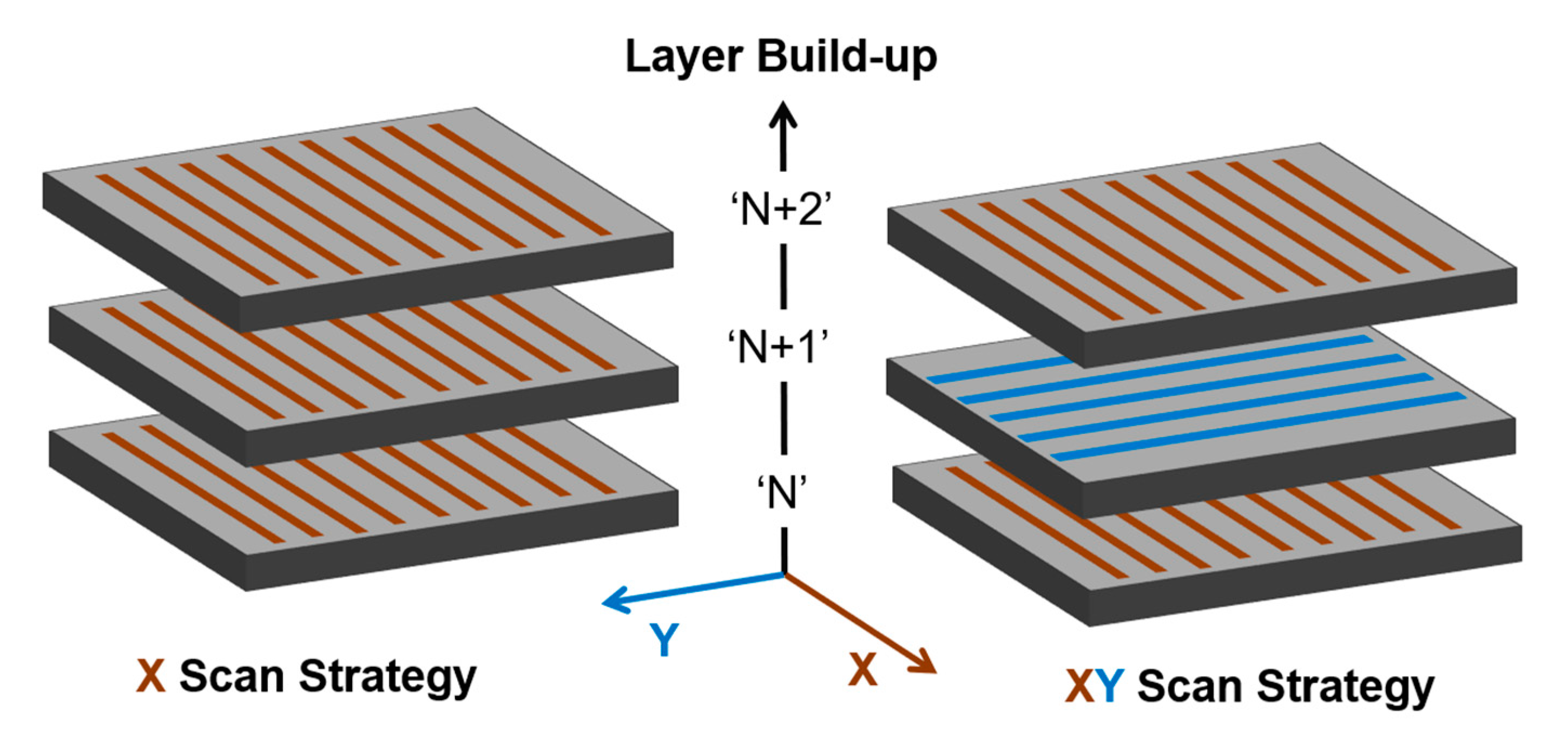
4.2.3. Laser Scan Strategy

Past research efforts have been mostly focused on processing parameters’ optimisation to achieve high-density parts, with less work conducted on assessing the effect of alternative laser scan strategies on the microstructural integrity and anisotropy of maraging steel 300 [38]. Yasa et al. [41] and Becker et al. [39] put forward proposals of laser re-melting (or double exposure) scan strategies as a solution towards decreasing unwanted porosity. Both studies demonstrated how such scan strategies can provide slight improvements to maraging steel 300’s relative density results. In their experiments, Becker et al. [39] selected suitable parameter settings and used these in conjunction with a double exposure scan-strategy to reduce the presence of voids to within 0.3% in the as-built metal (i.e., improving relative density from 99.5% to 99.7%). They scrutinised the effect of laser re-melting by performing tensile tests on specimens built with their longitudinal axis aligned at 0° and 90° to the build-plate. In the reported results, however, the marginal decrease in porosity achieved through laser re-melting (0.2%), is partnered by a considerable increase in tensile property anisotropy (i.e., Elasticity Modulus, yield strength and ductility). Whilst a single laser exposure scan-strategy produced material exhibiting a certain anisotropy, the second pass of the laser resulted in a significantly larger divergence in properties with respect to the build orientation. The results imply that residual stresses and/or preferred texture (perhaps promoted by this double exposure scan strategy), in conjunction with AM’s inherently anisotropic layer-wise macrostructure, may be at the root of the strength divergence. Residual stresses are suspected to be the cause of scattering witnessed in crack growth analysis in the same article. Additionally, when Yasa et al. [41] achieved hardness values 30% higher than the CM alloy, they assigned their reasoning to early-stage precipitation caused by the process’s intrinsic heating. It may be more plausible, however, that this premium hardness derived from compressive surface stresses is installed by the double exposure scan strategy. Although tailored scan strategies can be employed to eradicate porosity, the evidence suggests that these thermal processing events have ancillary effects that may adversely affect the performance of the produced part.
Becker et al. [39] and Bhardwaj et al. [38] showed that rotating the laser scan direction for subsequent build layers during AM build-up had a noticeable impact on the residual stress state in maraging steel 300. In these studies, measurements were performed on the top (free-surface), and base surface (after removal from the build-plate). Two scan strategies, X and XY—as shown in Figure 5—were compared. While both of these studies investigate the influence of the intra-layer laser scan rotation (90°) on surface/near-surface residual stresses, alternative residual stress characterisation techniques were employed and these produced conflicting results. In Figure 5N” represents an arbitrary build layer and subsequent layers are labelled “N + 1” and “N + 2”. Using x-ray diffraction, Bhardwaj et al. [38] detected compressive surface residual stresses for both X and X-Y strategies. Higher magnitude stresses, 25% of yield strength (0.25 × Rp0.2), were observed in material fabricated using the X scan strategy, whereas the X-Y strategy resulted in slightly lower magnitudes (0.2 × Rp0.2). This X-Y strategy was also beneficial towards reducing texture, and tensile specimens fabricated using this algorithm achieved higher yield strength and tensile strength, but lower ductility. Interestingly, these mechanical properties observations are believed to be related to a reduced (10%) presence (for this X-Y scan strategy) of retained austenite. Unfortunately, the authors do not specify the tensile specimens AM build orientation making it difficult to speculate further on the reported outcomes. Separately, Suryawanshi et al. [46] detected only weak fibre texture in the as-built condition and credited the absence of texture to their use of the X-Y strategy during the build-up. They did, however, notice that some grains appeared to be orientated in the laser scan direction, which may be a result of melt-pool solidification behaviour.
In contrast to Bhardwaj, Becker et al. [39], who determined near-surface residual stresses using the mechanical Strain-gage hole-drilling method (HDM), discovered 40% higher magnitude stresses approaching yield strength (0.7 × Rp0.2) in the material that had been fabricated using the X-Y strategy. Moreover, the stresses observed were tensile in nature which is clearly a contradictory finding. The residual stress variation between literature studies suggests there is a need for more comprehensive investigation using appropriate evaluation techniques. Becker et al. [39] do comment that the stress distributions were non-uniform and inconsistent between specimens, and attribute this to the AM process’s complex temperature gradients. Earlier work by Casavola et al. [79] employing HDM also observed high-magnitude tensile near-surface stresses (0.7 × Rp0.2) in the as-built condition. It is worth noting, however, that one of the fundamental limitations of the HDM method—which relies on the accurate measurement of strains which are caused by localised stress relaxation on the outside of a shallow hole as it is introduced incrementally into the stressed material—is that small experimental errors in strain measurement translate into larger calculated residual stresses. Even in the as-built condition, maraging steel exhibits a high Elasticity Modulus (E) (160 GPa) and high hardness (Vickers Hardness 350 kgf/mm2), making it a difficult alloy to characterise by sensitive mechanical methods. Nevertheless, it is clear from these studies that scan strategies play an important role in the development of residual stress and texture in the as-built material.
To date, AM scan strategy manipulation has played only a supporting or minor role in research concerning L-PBF maraging steel 300. Accordingly, the AM research and manufacturing community would benefit from a study that would fully characterise the effect of alternative scan strategies on the microstructural integrity, mechanical performance and anisotropy for this alloy.

4.2.4. Build Orientation and Heat Treatment

Anisotropy describes an uneven response of the alloy’s elastic and plastic properties (or flow–strain relationships) with respect to the AM build orientations. L-PBF maraging steel 300 has a major drawback against its CM counterpart. The mechanical properties are known to be anisotropic due to an inherent sensitivity with regards to how a part is orientated within the build volume [55,56,80]. This anisotropy is manifested through the fabrication process where large thermal gradients during melt-pool solidification, combined with the layer-wise deposition of the powder, planar movement of the heat-source, and uniaxial movement of the build-plate, make it difficult to homogenise the microstructure and mechanical properties of the as-built metal. As discussed, a microstructure of fine solidification cells, unique to the powder processing method and consequent to the powder granule melt dynamics, is coupled with continuous re-melting/heating of material beneath the melt-pool during the build-up. This causes a distinct three-dimensional microstructural pattern to form and results in mechanical properties which vary with direction (anisotropy). In the case of the EOS MS1, the material becomes isotropic following the application of a specified ageing heat treatment (6 h at 490 °C), according to the EOS material datasheet (MDS) [55]. However, the MDS is not sufficient to characterise the material performance for engineering designs and products, since it covers only the primary build orientations (0° and 90°), and comes from a single source (EOS, the L-PBF equipment manufacturer).
In contrast to CM maraging steel 300, and by reason of the rapid melt-pool cooling rates, the L-PBF process provides a solid solution with full potential for precipitation strengthening [17]. As discussed, rapid cooling creates a metastable martensite structure which is supersaturated with respect to the solute [15,28,29,52]. This affords the heat treater/AM practitioners with an opportunity to by-pass solution annealing and commence precipitation-hardening directly post-fabrication, which allows for a much-accelerated fabrication route than that of the CP-alloy. The effectiveness of both the L-PBF fabrication and heat-treatment process can only be measured by the extent to which the as-built and heat-treated component behaves under mechanical loading. However, limited published research exists to date concerning the build orientation influence on mechanical behaviour of AM produced maraging steel 300 [66,81,82,83,84,85]. Croccolo et al. [82], who investigated the dependence of build orientation relative to the build plane (0°, 45°, and 90°) on the high cycle fatigue life of EOS M280 produced MS1 specimens in the aged (6 h at 490 °C) condition only, found no substantial difference on the fatigue properties. Monkova et al. [81] examined the tensile properties of EOS MS1 fabricated at 0°, 45°, and 90°, and contrary to the EOS published MDS [55] they observed no significant orientation dependence in the tensile stress-strain behaviour for as-built, solution heat-treated (1 h at 820 °C), and aged (6 h at 490 °C) material.
Mooney at al. [84] examined a wide array of strengthening heat treatment plans to assess the influence of thirty combinations of time and temperature on mechanical properties and plastic anisotropy of maraging steel 300 fabricated at 0°, 45°, and 90°. Of note is that considerable anisotropy has been confirmed in [84] for the as-built condition, which can be drastically reduced via ageing heat treatment. Other available test data mainly cover static testing (tensile, and/or hardness) of maraging steel specimens fabricated in only one [13,16,17,45,51,66,67,77,83,86], or two [28,39,46,49,80] of the primary AM build orientations. One of the most comprehensive of these studies in terms of the reported mechanical properties is that of Jägle et al. [17], which has monitored the effect of an array of aging heat-treatments on the static properties of the L-PBF alloy. While the study presents a broad range of hardness results, limited tensile properties are reported (i.e., for the as-built and five other peak-aged heat-treatment conditions). Furthermore, only the horizontal (0°) build-orientation is considered. Yin et al. [54], Bai et al. [40] and Mutua et al. [49] also present hardness and tensile data for horizontal specimens tested under a narrow array of aging treatments. In these studies, however, non-characteristic fluctuations/ variations in the AM alloy’s elastic and plastic behaviour can be observed. While explanations for these abnormalities are not asserted, they may indeed be introduced during the fabrication process and/or during the material characterisation process (e.g., due to the tensile test rates employed).
Maraging steel 300 is rarely used in the as-built state, and Becker et al. [39] account for the effectiveness of heat treatment on residual stress relaxation. The authors demonstrated that by subjecting the material to a post-AM solution anneal, residual stress magnitudes could be relieved by up to 80% and the properties (now akin to those of CP-material) exhibited their most isotropic state (albeit with 26% reduction in yield strength). The evidence suggests that the solution anneal is undoubtedly effective in reducing the residual stress state, however, this superfluous process-step incurs additional processing cost and complexity and subtracts from the overall maraging steel 300 AM appeal. An ageing heat treatment cycle is the natural route to enhance the alloy’s strength capabilities, however, on its own, ageing at moderate temperatures (e.g., 440–540 °C) seems capable only to provide partial stress relief.
Croccolo et al. [82] allege that the standard ageing treatment of 6 h at 490 °C is particularly effective at reducing residual stresses in maraging steel 300, however, a lack of research knowledge regarding stress relaxation by cause of ageing make its effectiveness inscrutable. In this context, a better comprehension of the link between the alloy’s ageing heat-treatment and the suppression of factors such as texture and residual stress, which influence mechanical performance and property anisotropy, is required. Such a study could also incorporate alternative scan strategies and build orientations in its appraisal.

4.3. Mechanical Properties

Non-standardisation of machine-powder variable settings across the metal AM landscape leads to variations in the microstructural evolution, austenite retention, and presence of defects in fabricated parts. These issues, in conjunction with the use of an assortment of standard/non-standard test-coupon geometries (e.g., flat and cylindrical) and mechanical testing rates in the research literature, have resulted in a spread in the published monotonic properties of L-PBF maraging steel 300. The results for as-built and the heat-treated material are presented in the following subsections.

4.3.1. As-built Material

There is a variation in the L-PBF maraging steel 300 properties reported in the published literature for contrasting test-coupon geometries which have been fabricated on various systems [13,17,39,46,47,48,49,51,55,66,67,80,81,84,86]. The spread of the as-built tensile properties reported across these studies (i.e., Elasticity Modulus (E): 150–194 GPa; yield strength (Rp0.2): 768–1214 MPa; tensile strength (Rm): 1010–1325 MPa; and elongation at break (At): 6.1–14.3%) is a measure of the variability observed. The tensile yield strength (Rp0.2) and elongation (At) at break values measured across various research studies conducted on maraging steel 300 are plotted in Figure 6, offering a better visualisation of the wide-spread variability observed. For reference, the values published by EOS in their material datasheet (MDS) for MS1 are included in the plot.
Of note are the results obtained by Meneghetti et al. [87]. The red circled data points shown in Figure 6 are the values published by EOS in their MDS for MS1 [55], while circled in black are properties reported by Meneghetti et al. [87]. Both of these groups highlight anisotropic as-built properties since values for the horizontal (circular symbol) and vertically orientated (square symbol) test-specimens do not overlap. The plus (+) symbol is used where the author has not specified the build direction of the tested parts. As shown, both the EOS [55] (red circled) data and Meneghetti et al. [87] (black circled) data, which report properties for horizontal (0°) and vertical (90°) build orientations, provide evidence that a certain stress and strain anisotropy exists in the as-built metal. There is, however, a lack of consensus between Meneghetti et al. [87] reported tensile data and their concluding remarks where they comment that there is no difference in terms of mechanical properties between specimen build orientation. It is also worth noting that this study reports unusually high elongation (At) properties for the as-built EOS MS1, as also shown in Figure 6.

4.3.2. Heat-Treated (Aged) Material

Understandably, the quality of the as-built metal will govern its mechanical performance in the aged condition, and that various combinations of ageing time and temperature will give contrasting mechanical properties outcomes in maraging steel 300. Yasa et al. [41] was the first openly published study to examine optimisation of the ageing heat-treatment of maraging steel 300. The study demonstrated how increased hardness, approximately 10% greater than the CP-alloy, could be achieved in the AM alloy. However, as-expected, ductility and toughness were markedly reduced to values lower than the CP-alloy (AM ductility: 1.5% versus CP: 7%).
Other authors also report lower ductility in the L-PBF and heat-treated (aged) material [17,45,47,72]. Casati et al. [17] rationalise AM’s comparatively poor ductility and toughness by speculating that the retained austenite at cell boundaries is so fine and well-dispersed, that it prevents any substantial toughening as further reversion takes place during ageing. Certainly, studies covering the conventional welding of maraging steel relate poor weld toughness to high energy inputs which involve prolonged high-temperature exposure and slower cooling rates. This condition can lead to a coarse and segregated structure and encourages precipitation at grain boundaries and thus embrittlement [18]. In a continuation of the work by Yasa et al. [41], the same group of researches [51] found the best ageing parameters, in terms of developing optimum hardness, to be 5 h at 480 °C. With this t, T combination, a hardness of 58 HRC was achieved. Contuzzi et al. [83] accomplished comparable optimum hardness (57 HRC) in his brief conference article, but this was achieved after 15 h at 500 °C, whereas Mutua et al. [49] identified 5 h at 460 °C as their optimum heat treatment plan. Campanelli et al [88] performed an extensive hardness measurement (HV) campaign on solution treated and aged SLM MS300 in a range of t, T combinations (0.25–25 h and 440–560 °C). The maximum hardness value (700 HV) was achieved for 10 h at 480 °C heat treatment. Casati et al. [17] investigated the effects of a more expansive range of ageing parameters (t, T) on the hardness of AM-processed maraging steel 300. The strengthening trend as a function of ageing time for the various temperatures revealed the peak hardness for a given t, T combination. These peak conditions were then examined further on tensile test-specimens which were built in the horizontal (0°) orientation. The measured properties reflected the observed changes in the microstructure (i.e., increase in austenite with t, T). The maximum yield strength obtained (Rp0.2 = 1957 ± 43 MPa after 8 h at 460 °C) is comparable to the typical EOS MS1 achievable value, but EOS specify a different t, T combination (Rp0.2 = 1990 ± 100 MPa after 6 h at 490 °C).
It is evident that no two studies have identified an equivalent optimum heat treatment (ageing) cycle for strength/hardness in the L-PBF alloy. The variety suggests skepticism about the most appropriate ageing parameters, not only in terms of amassing strength and hardness (which has been the focus of these studies in the past), but also in identifying the best combination of t, T to embody ductility and toughness. When increased ductility is sought in MS1, EOS suggest an ageing treatment of 6h at 525 °C (−600 °C) [89], however until now, there has been no published tensile data available for the appraisal of these ageing parameters (either from EOS or the research literature). The formulation of a full and robust evaluation of the wide-scale heat treatment and build orientation influences on the monotonic tensile properties of L-PBF maraging steel, as presented in this study, is therefore much needed.
The populous presence of blocking precipitates, as well as giving maraging steel outstanding strength and hardness in the aged condition, are also highly effective at concealing anisotropic mechanical behaviour. In that context, EOS publish isotropic data for MS1 in its aged condition [55]. However, a certain stress and strain anisotropy is evident in Suryawanshi et al. [46], Mooney et al. [84] and Meneghetti et al. [87] aged yield strength (Rp0.2) and elongation (At) experimental data which are presented in Figure 7. As before, this plot intends to highlight a large degree of mechanical properties variation observed within and between literature studies for maraging steel 300 which has been aged to achieve optimal strength. From the data presented, it is worth noting that Suryawanshi et al. [46] downplayed a strength difference (117 MPa) between 0° and 90° build orientations as “marginal”, whereas a strain anisotropy of 5% was not highlighted by Meneghetti et al. [87]. Anisotropy can also be observed in Suryawanshi’s crack-growth resistance results which show that vertical (90°) specimens display a slightly higher rate of crack-growth than horizontal (0°) specimens, however, this too is not highlighted by the authors. Moreover, it is noted that the Mooney et al. [84] obtained results suggest that induced anisotropy is not possible to be eliminated by applying the 6 h at 490 °C heat treatment, while this plan does not optimise the alloy’s performance in terms of strength, ductility and hardness.
The direct comparison of stress versus strain behaviour between alternative build orientations (i.e., by superimposing the data on a plot) can provide very valuable information on the AM alloy’s mechanical response, whereas, on their own, the “fixed value” properties derived from these plots may lead to anisotropic behavior being overlooked. To date, however, only one study by Meneghetti et al. [87] provides a visual insight into the anisotropic (elastic and plastic) maraging steel 300 material response by supporting the derived mechanical properties of horizontal and vertically orientated test-coupons with their corresponding superimposed—curves. In this study, both elastic and plastic anisotropy can be observed in the as-built alloy’s—plotted paths, however as mentioned above, the derived mechanical properties do not effectively communicate this observation, nor was it highlighted by the authors. They recorded similar derived mechanical property values (Elasticity Modulus, yield strength, tensile strength and ductility) for specimens fabricated at alternative build orientations (0° and 90°) in both as-built and heat-treated (aged) material conditions. Upon ageing, the tensile elastic anisotropy previously observed in the as-built—curves is largely reduced. Nonetheless, a slight strength difference between build orientations is reflected in the aged material’s plastic response (i.e., between the material’s yield point through failure).
Croccolo et al. [82] revealed fatigue strength anisotropy in aged EOS MS1 test-specimens grown at three different angles (0°, 45°, and 90°) between the specimen’s longitudinal axis and the build direction. This experimental study executed a robust fabrication process using the EOSINT M280 AM machine with supplier’s (EOS) pre-optimised parameter-set (Performance 2.0 for MS1) to manufacture standardised specimens which were then shot-peened, precipitation hardened (6 h at 490 °C), and shot-peened once more prior to finish-grinding. This cautious sample preparation sequence, plus the fact that the alloy had been aged to obtain peak strength, rationalises the results achieved. No significant disparity was observed in the fatigue strength between build-orientations. Still, the 45° and 90° specimens displayed lower fatigue limits, albeit marginal (1.6%, 2.6%), than horizontal specimens. Residual stresses may be a contributory factor here since it is known that they are positively correlated with increasing build height [90,91] and suggests that through-thickness, property-altering, residual stresses may remain in the material after the prescribed EOS ageing (6 h at 490 °C) and shot-peening treatments.

5. Conclusions

This review identified and discussed a number of factors contributing to the variability of the L-PBF maraging steel 300 mechanical properties reported in the published literature. These findings can be helpful in guiding further research efforts in the AM manufacturing and post-processing arena. A summary of some of the key findings is provided below:
  • Not only the quality of the powder but also its morphology can play an important role in achieving higher relative density and optimising mechanical properties.
  • Processing parameters directly influence the material microstructure, which in turn has an impact on the mechanical properties and anisotropic characteristics of the material. Moreover, in an effort to control density and porosity levels when manipulating processing parameters, adverse results may be obtained in terms of anisotropy.
  • Laser scan strategy is a complex problem for material properties’ optimisation, yet it offers an opportunity for further research on how alternate strategies may offer not improved anisotropy.
  • The build orientation influence on the mechanical performance of the material is best to be examined in conjunction with heat treatment plans. Anisotropy can be drastically reduced via an appropriate choice of such plans, which are generally easy to implement for this material. In addition, the growing body of research in this field is expected to inform changes in the way heat treatments are selected relative to the sought mechanical properties.

Author Contributions

Conceptualization, B.M. and K.I.K.; methodology, B.M. and K.I.K.; formal analysis, B.M.; investigation, B.M.; resources, B.M.; data curation, B.M.; writing—original draft preparation, B.M. and K.I.K.; writing—review and editing, B.M. and K.I.K.; visualization, B.M. and K.I.K.; supervision, K.I.K..; project administration, B.M. and K.I.K.; funding acquisition, B.M. and K.I.K. All authors have read and agreed to the published version of the manuscript.

Funding

This research was funded by the Irish Research Council, through the Government of Ireland Postgraduate Research Programme.

Conflicts of Interest

The authors declare no conflict of interest. The funders had no role in the design of the study; in the collection, analyses, or interpretation of data; in the writing of the manuscript, or in the decision to publish the results.

References

  1. EOS. Materials for Metal Additive Manufacturing. EN. Electro Optical Systems. 2017. Available online: https://www.eos.info/en/additive-manufacturing/3d-printing-metal/dmls-metal-materials (accessed on 14 June 2020).
  2. Wohlers, T.; Gornet, T. History of Additive Manufacturing. White Paper. Wohlers Associates. 2014, p. 34. Available online: http://wohlersassociates.com/history2014.pdf (accessed on 2 November 2017).
  3. Carter, L.N.; Martin, C.; Withers, P.J.; Attallah, M.M. The influence of the laser scan strategy on grain structure and cracking behaviour in SLM powder-bed fabricated nickel superalloy. J. Alloys Compd. 2014, 615 (Suppl. C), 338–347. [Google Scholar] [CrossRef]
  4. Herzog, D.; Seyda, V.; Wycisk, E.; Emmelmann, C. Additive manufacturing of metals. Acta Mater. 2016, 117 (Suppl. C), 371–392. [Google Scholar] [CrossRef]
  5. Ahuja, B.; Schaub, A.; Junker, D.; Karg, M.; Tenner, F.; Plettke, R.; Merklein, M.; Schmidt, M. A round robin study for leaser beam melting in a metal powder bed. S. Afr. J. Ind. Eng. 2016, 27, 30–42, ISSN 1012-277X. [Google Scholar] [CrossRef] [Green Version]
  6. Bassoli, E.; Gatto, A.; Sewell, N.T.; Johns, D. On the effects of build orientation in powder-fed Additive Layer Manufacture of steel 316L. In Innovative Developments in Design and Manufacturing. Advanced Research in Virtual and Rapid Prototyping. 4th International Conference on Advanced Research and Rapid Prototyping. (Liberia, Portugal); CRC Press: Rotterdam, The Netherlands, 2010; pp. 263–268. ISBN 9781439859216. [Google Scholar]
  7. Appleyard, D. Powering up on powder technology. Met. Powder Rep. 2015, 70, 285–289, ISSN 0026-0657. Available online: http://www.sciencedirect.com/science/article/pii/S0026065715005184 (accessed on 6 October 2017). [CrossRef]
  8. Scott, D. Add It up: 5 Industrial Additive Manufacturing Trends for 2017. Autodesk. 2017. Available online: https://www.autodesk.com/redshift/industrialadditive-manufacturing-trends/ (accessed on 5 October 2017).
  9. Singh, S.; Ramakrishna, S.; Singh, R. Material issues in additive manufacturing: A review. J. Manuf. Process. 2017, 25 (Suppl. C), 185–200. [Google Scholar] [CrossRef]
  10. Grand-View-Research. 3D Metal Printing Market Analysis By Product (Titanium, Nickel, Steel, Aluminum), By Application (Aerospace and Defense, Automotive, Medical and Dental), By Form (Powder, Filament), By Region, By Country, And Segment Forecasts, 2014–2025. Annual Report 4312495. Research and Markets. May 2017, p. 90. Available online: https://www.researchandmarkets.com/research/j37c7h/3d_metal_printing (accessed on 5 October 2017).
  11. Davis, J.R. (Ed.) Alloying: Understanding the Basics; ASM International: Materials Park, OH, USA, 2001; ISBN 978-0-87170-744-4. [Google Scholar]
  12. Hall, A.M.; Slunder, C.J. The Metallurgy, Behaviour, and Application of the 18-Percent Nickel Maraging Steels. Survey 20000828 057. SP-5051. NASA. 1968. Available online: http://www.dtic.mil/dtic/tr/fulltext/u2/a382105.pdf (accessed on 14 June 2020).
  13. Stanford, M.; Kibble, K.; Lindop, M.; Mynors, D.; Durnall, C. An investigation into fully melting a maraging steel using Direct Metal Laser Sintering (DMLS). In Proceedings of the Special Edition Metal Forming Conference, Krakow, Poland, 21–24 September 2008; Volume 2, pp. 847–852. [Google Scholar]
  14. Sha, W.; Guo, Z. Maraging Steels, Modelling of Microstructure, Properties and Applications; Woodhead Publishing: Cambridge, UK, 2009; ISBN 978-1-84569-686-3. [Google Scholar]
  15. ASM International. ASM Handbook Volume 4: Heat Treating; ASM International: Materials Park, OH, USA, 1991; Volume 4. [Google Scholar]
  16. Jägle, E.A.; Sheng, Z.; Wu, L.; Lu, L.; Risse, J.; Weisheit, A.; Raabe, D. Precipitation reactions in age-hardenable alloys during laser additive manufacturing. JOM 2016, 68, 943–949. [Google Scholar] [CrossRef] [Green Version]
  17. Casati, R.; Lemke, J.N.; Tuissi, A.; Vedani, M. Aging behaviour and mechanical performance of 18-Ni 300 steel processed by selective laser melting. Metals 2016, 6, 218. [Google Scholar] [CrossRef]
  18. Lang, F.H.; Kenyon, N. WRC Bulletin: Welding of Maraging Steels; Technical Report 159; Welding Research Council: New York, NY, USA, 1971. [Google Scholar]
  19. Sercombe, T.B. Sintering of freeformed maraging steel with boron additions. Mater. Sci. Eng. A 2003, 363, 242–252. [Google Scholar] [CrossRef]
  20. Casavola, C.; Campanelli, S.L.; Pappalettere, C. Experimental Analysis of Residual Stresses in the Selective Laser Melting Process. In Proceedings of the XIth International Congress and Exposition; Society for Experimental Mechanics Inc.: Orlando, FL, USA, 2008. [Google Scholar]
  21. Renishaw. Digging Deep with Wassara; Case Study H-5800-4015-01; Renishaw: Wotton-under-Edge, UK, 2018; Available online: http://www.renishaw.com/en/digging-deep-withwassara--43252 (accessed on 10 July 2020).
  22. Tariq, F.; Naz, N.; Rasheed, A.B. Effect of cyclic aging on mechanical properties and microstructure of maraging steel 250. J. Mater. Eng. Perform. 2010, 19, 1005–1014. [Google Scholar] [CrossRef]
  23. Kleiner, L.M.; Simonov, Y.N. Structure and properties of low-carbon martensitic steels. Met. Sci. Heat Treat. 1999, 41, 366–368. [Google Scholar] [CrossRef]
  24. Inco. 18 per Cent Maraging Steels; Engineering Properties. Tech. Rep. 4419; International Nickel Company, Inco Euro Limited: Brussels, Belgium, 1976; p. 30. [Google Scholar]
  25. Davis, J.R. (Ed.) ASM Specialty Handbook: Tool Materials; ASM International: Materials Park, OH, USA, 2005; ISBN 9780871705457. [Google Scholar]
  26. Abrahamson, E.P. Processing and Properties on 18Ni Maraging Steel by Powder Metallurgy; Tech. Rep. AD 758439. AMMRC TR 73-4.; Army Materials and Mechanics Research Center: Watertown, MA, USA, 1973. [Google Scholar]
  27. Shekhter, A.; Aaronson, H.I.; Miller, M.R.; Ringer, S.P.; Pereloma, E.V. Effect of aging and deformation on the microstructure and properties of Fe- Ni-Ti maraging steel. Metall. Mater. Trans. A 2004, 35, 973–983. [Google Scholar] [CrossRef]
  28. Casati, R.; Lemke, J.; Vedani, M. Microstructural and Mechanical Properties of as Built, Solution Treated and Aged 18 Ni (300 grade) Maraging Steel Produced by Selective Laser Melting. La Metall. Ital. 2017, 11–20. Available online: http://www.aimnet.it/la_metallurgia_italiana/2017/gennaio/Casati.pdf (accessed on 14 June 2020).
  29. Jägle, E.A.; Choi, P.P.; van Humbeeck, J.; Raabe, D. Precipitation and austenite reversion behavior of a maraging steel produced by selective laser melting. J. Mater. Res. 2014, 29, 2072–2079. [Google Scholar] [CrossRef] [Green Version]
  30. Viswanathan, U.K.; Dey, G.K.; Sethumadhavan, V. Effects of austenite reversion during overageing on the mechanical properties of 18 Ni (350) maraging steel. Mater. Sci. Eng. A 2005, 398, 367–372. [Google Scholar] [CrossRef]
  31. Niendorf, T.; Leuders, S.; Riemer, A.; Richard, H.A.; Tröster, T.; Schwarze, D. Highly Anisotropic Steel Processed by Selective Laser Melting. Metall. Mater. Trans. B 2013, 44, 794–796, ISSN 1543-1916. [Google Scholar] [CrossRef] [Green Version]
  32. Kunze, K.; Etter, T.; Grässlin, J.; Shklover, V. Texture, anisotropy in microstructure and mechanical properties of IN738LC alloy processed by selective laser melting (SLM). Mater. Sci. Eng. A 2015, 620 (Suppl. C), 213–222. [Google Scholar] [CrossRef]
  33. Brown, C.U.; Donmez, A. NIST Advanced Manufacturing Series. In Microstructure Analysis for Additive Manufacturing: A Review of Existing Standards; Report 100-3; NIST: Gaithersburg, MD, USA, 2016; p. 27. [Google Scholar] [CrossRef]
  34. Etter, T.; Kunze, K.; Geiger, F.; Meidani, H. Reduction in mechanical anisotropy through high temperature heat treatment of Hastelloy X processed by Selective Laser Melting (SLM). IOP Conf. Ser. Mater. Sci. Eng. 2015, 82, 012097. [Google Scholar] [CrossRef]
  35. Dieter, G.E. Mechanical Metallurgy; McGraw-Hill: New York, NY, USA, 1961. [Google Scholar]
  36. Thijs, L.; Kempen, K.; Kruth, J.; van Humbeeck, J. Fine-structured aluminium products with controllable texture by selective laser melting of pre-alloyed AlSi10Mg powder. Acta Mater. 2013, 61, 1809–1819. [Google Scholar] [CrossRef] [Green Version]
  37. AlMangour, B.; Grzesiak, D.; Yang, J.M. Rapid fabrication of bulk-form TiB2/316L stainless steel nanocomposites with novel reinforcement architecture and improved performance by selective laser melting. J. Alloys Compd. 2016, 680, 480–493. [Google Scholar] [CrossRef]
  38. Bhardwaj, T.; Shukla, M. Effect of laser scanning strategies on texture, physical and mechanical properties of laser sintered maraging steel. Mater. Sci. Eng. A 2018, 734, 102–109, ISSN 0921-5093. [Google Scholar] [CrossRef]
  39. Becker, T.H.; Dimitrov, D. The achievable mechanical properties of SLM produced Maraging Steel 300 components. Rapid Prototyp. J. 2016, 22, 487–494. [Google Scholar] [CrossRef]
  40. Bai, Y.; Yang, Y.; Wang, D.; Zhang, M. Influence mechanism of parameters process and mechanical properties evolution mechanism of maraging steel 300 by selective laser melting. Mater. Sci. Eng. A 2017, 703 (Suppl. C), 116–123. [Google Scholar] [CrossRef]
  41. Yasa, E.; Deckers, J.; Kruth, J.P.; Rombouts, M.; Luyten, J. Experimental investigation of Charpy impact tests on metallic SLM parts. In Innovative Developments in Design and Manufacturing Advanced Research in Virtual and Rapid Prototyping; CRC Press-Taylor Francis Group: Leiria, Portugal, 2009; pp. 214–217. Available online: https://lirias.kuleuven.be/bitstream/123456789/224820/2/Yasa_VRAP_2009_submitted.pdf (accessed on 24 November 2017).
  42. Frazier, W.E. Metal additive manufacturing: A review. J. Mater. Eng. Perform. 2014, 23, 1917–1928. [Google Scholar] [CrossRef]
  43. Glaser, R.; Goel, R.; Hewitt, M.; Meng, F.; Wang, P.; Yan, R. 3D Printing Alloys; Report; Northwestern University: Evanston, IL, USA, 2015; Available online: https://canvas.northwestern.edu/files/2229202/download?download_frd=1&verifier=N8bi8oUaRn08EPsKLapRweNJAdhdKg2PH0jtJdIJ (accessed on 28 October 2017).
  44. Campanelli, S.L.; Contuzzi, N.; Angelastro, A.; Ludovico, A.D. NewTrends in Technologies: Devices, Computer, Communication and Industrial Systems; IntechOpen: London, UK, 2010; Chapter 13, Capabilities and Performances of the Selective Laser Melting Process; pp. 233–252. [Google Scholar]
  45. Tan, C.; Zhou, K.; Tong, X.; Huang, Y.; Jing, J.; Ma, W.; Li, F.; Kuang, T. Microstructure and Mechanical Properties of 18Ni-300 Maraging Steel Fabricated by Selective Laser Melting. In Proceedings of the 6th International Conference on Advanced Design and Manufacturing Engineering (ICADME 2016); Atlantis Press: Amsterdam, The Netherlands, 2016; pp. 404–410. [Google Scholar] [CrossRef] [Green Version]
  46. Suryawanshi, J.; Prashanth, K.G.; Ramamurty, U. Tensile, fracture, and fatigue crack growth properties of a 3D printed maraging steel through selective laser melting. J. Alloys Compd. 2017, 725 (Suppl. C), 355–364. [Google Scholar] [CrossRef]
  47. Bourdil, D. (Ed.) Microstructure and Mechanical Properties of Maraging Steel 300 after Selective Laser Melting. Solid Freeform Fabrication Symposium. (Texas, Aug. 12, 2010). USA. August 2010, pp. 383–396. Available online: https://sffsymposium.engr.utexas.edu/Manuscripts/2010/2010-32-Yasa.pdf (accessed on 8 August 2017).
  48. Tan, C.; Zhou, K.; Ma, W.; Zhang, P.; Liu, M.; Kuang, T. Microstructural evolution, nanoprecipitation behavior and mechanical properties of selective laser melted high-performance grade 300 maraging steel. Mater. Des. 2017, 134, 23–34. [Google Scholar] [CrossRef]
  49. Mutua, J.; Nakata, S.; Onda, T.; Chen, Z.C. Optimization of selective laser melting parameters and influence of post heat treatment on microstructure and mechanical properties of maraging steel. Mater. Des. 2018, 139, 486–497. [Google Scholar] [CrossRef]
  50. Morito, S.; Tanaka, H.; Konishi, R.; Furuhara, T.; Maki, T. The morphology and crystallography of lath martensite in Fe-C alloys. Acta Mater. 2003, 51, 1789–1799. [Google Scholar] [CrossRef]
  51. Kempen, K.; Yasa, E.; Thijs, L.; Kruth, J.-P.; van Humbeeck, J. Microstructure and mechanical properties of Selective Laser Melted 18Ni-300 steel. Lasers in Manufacturing 2011; In Proceedings of the Sixth International WLT Conference on Lasers in Manufacturing. Phys. Procedia 2011, 12, 255–263, ISSN 1875-3892. [Google Scholar] [CrossRef] [Green Version]
  52. Jägle, E.A.; Sheng, Z.; Kurnsteiner, P.; Ocylok, S.; Weisheit, A.; Raabe, D. Comparison of Maraging Steel Micro- and Nanostructure Produced Conventionally and by Laser Additive Manufacturing. Materials 2017, 10, 8. [Google Scholar] [CrossRef] [Green Version]
  53. Shamantha, C.R.; Narayanan, R.; Iyer, K.J.L.; Radhakrishnan, V.M.; Seshadri, S.K.; Sundararajan, S.; Sundaresan, S. Microstructural changes during welding and subsequent heat treatment of 18Ni (250-grade) maraging steel. Mater. Sci. Eng. A 2000, 287, 43–51. [Google Scholar] [CrossRef]
  54. Yin, S.; Chen, C.; Yan, X.; Feng, X.; Jenkins, R.; O’Reilly, P.; Liu, M.; Li, H.; Lupoi, R. The influence of aging temperature and aging time on the mechanical and tribological properties of selective laser melted maraging 18Ni-300 steel. Addit. Manuf. 2018, 22, 592–600. [Google Scholar] [CrossRef]
  55. EOS. EOS MaragingSteel MS1; Material data sheet EOSINT M280 EOSINT M270; EOS GmbH: Munich, Germany, 2011; p. 6. Available online: http://ip-saas-eos-cms.s3.amazonaws.com/public/1af123af9a636e61/042696652ecc69142c8518dc772dc113/EOS_MaragingSteel_MS1_en.pdf (accessed on 14 June 2020).
  56. Renishaw. Maraging Steel M300 Powder for Additive Manufacturing; Data sheet; Renishaw: New Mills, UK, 2017; p. 2. Available online: http://resources.renishaw.com/en/download/data-sheet-maraging-steel-m300-for-200-w-powder-for-additive-manufacturing--96325 (accessed on 14 June 2020).
  57. Concept Laser. CL 50WS Hot Work Steel 1.2709 Powder. Material Data Sheet; Concept Laser: Lichtenfels, Germany, 2016; p. 2. Available online: https://www.concept-laser.de/fileadmin//user_upload/Datasheet_CL_50WS.pdf (accessed on 15 August 2018).
  58. 3D Systems. LaserForm Maraging Steel (B) for ProX DMP 200 and 300 Direct Metal Printers; Material Product Data Sheet; 3D Systems: Rock Hill, SC, USA, 2017; p. 1. Available online: https://www.3dsystems.com/materials/maraging-steel (accessed on 19 September 2017).
  59. Oerlikon. Maraging Steel (C300) Type Powder for Additive Manufacturing; Material Product Data Sheet; Oerlikon AG: Pfäffikon, Switzerland, 2017; p. 1. Available online: https://www.oerlikon.com/metco/en/ (accessed on 19 September 2017).
  60. LPW. Powder Range. Metal Powders from LPW. Material Data Sheet; LPW Technologies: Widnes, UK, 2016; p. 12. Available online: http://www.lpwtechnology.com/wp-content/uploads/2016/11/LPW_Powders_Brochure.pdf (accessed on 19 September 2017).
  61. 3TRPD. Maraging Steel 1.2709 (Source EOS). Material Specification; 3TRPD: 3T Additive Manufacturing: Fulton Court, UK, 2012; p. 1. Available online: http://www.3trpd.co.uk/wp-content/uploads/2013/03/maraging-steel-1-2709-2012.pdf (accessed on 19 September 2017).
  62. Sandvik Materials Technology. Sandvik Osprey Metal Powders; Tech. Rep.; Sandvik Materials Technology Ltd.: Halesowen, UK, 2010; Available online: https://www.materials.sandvik/globalassets/global/downloads/products_downloads/metal_powders/s-po009-ps-eng-09.2010.pdf (accessed on 10 July 2020).
  63. LPW Technology. Case Study: Maraging Steel—The Effects of Alloy Chemistry on Processability. Case Study. LPW. August 2017. Available online: https://www.lpwtechnology.com/wp-content/uploads/2017/08/Case-Study-M300.pdf (accessed on 10 July 2020).
  64. LPW Technology. Case Study: The Impact of Powder Variability on Additive Manufacturing Build Quality. Case Study. LPW. May 2018. Available online: https://www.lpwtechnology.com/wp-content/uploads/2018/05/Case-Study-12-ALSi10Mg-Final.pdf (accessed on 10 July 2020).
  65. Sutton, A.T.; Kriewall, C.S.; Leu, M.C.; Newkirk, J.W. Powders for Additive Manufacturing Processes: Characterization Techniques and Effects on Part Properties. In Proceedings of the 26th Annual International Solid Freeform Fabrication Symposium, Austin, TX, USA, 8–10 August 2016. [Google Scholar]
  66. Burkert, T.; Fischer, A. The Effects of Heat Balance on the Void Formation within Marage 300 Processed by Selective Laser Melting. In International Solid Freeform Fabrication Symposium; University of Texas: Austin, TX, USA, 2015; pp. 745–757. Available online: http://sffsymposium.engr.utexas.edu/sites/default/files/2015/2015-61-Burkert.pdf (accessed on 14 June 2020).
  67. Koutney, D.; Panteljev, L.; Tomes, J.; Palousek, D. Comparison of selective laser melting of 18NI maraging steel by PXL and M2 cusing. Mod. Mach. Sci. J. 2016, 180, 1590–1596. [Google Scholar] [CrossRef]
  68. Kempen, K. Expanding the Materials Palette for Selective Laser Melting of Metals. In Dissertation. KU Leuven—Faculty of Engineering Science; Katholieke Universiteit Leuven: Leuven, Belgium, 2015. [Google Scholar]
  69. Masneri, C. Microstructural and Mechanical Properties of Maraging Steel Parts Produced by Selective Laser Melting. Master’s Thesis, Politecnico Milano, Milan, Italy, 2016. [Google Scholar]
  70. Renishaw. Investigating the Effects of Multiple Re-Use of Ti6Al4V Powder in Additive Manufacturing (AM). White Paper. Renishaw. 2016. Available online: http://resources.renishaw.com/en/details/white-paper-investigatingthe-effects-of-multiple-powder-re-use-in-am--83164 (accessed on 10 July 2020).
  71. Quinn, P.T.; O’Halloran, S.M.; Lawlor, J.; Raghavendra, R. Characterization of Recycled Powders and Resulting Properties Derived From Additive Manufacturing. In Proceedings of the Preliminary Proceedings: 35th International Manufacturing Conference (IMC35), 20 June 2018; Dublin Institute of Technology: Dublin, Ireland, 2018; pp. 8–11. [Google Scholar]
  72. Hoeges, S.; Schade, C.T.; Causton, R. Development of a Maraging Steel Powder for Additive Manufacturing. In Proceedings of the MPIF World Congress on Powder Metallurgy and Particulate Materials, San Diego, CA, USA, 17–28 May 2015; pp. 17–28. [Google Scholar]
  73. Montazeri, M.; Yavari, R.; Rao, P.; Boulware, P. In-Process Monitoring of Material Cross-Contamination Defects in Laser Powder Bed Fusion. ASME. J. Manuf. Sci. Eng. 2018, 140, 111001. [Google Scholar] [CrossRef]
  74. Mahmoudi, M.; Ezzat, A.A.; Elwany, A. Layerwise Anomaly Detection in Laser Powder-Bed Fusion Metal Additive Manufacturing. ASME. J. Manuf. Sci. Eng. 2019, 141, 031002. [Google Scholar] [CrossRef]
  75. Polozov, I.; Sufiiarov, V.; Kantyukov, A.; Razumov, N.; Goncharov, I.; Makhmutov, T.; Silin, A.; Kim, A.; Starikov, K.; Shamshurin, A.; et al. Microstructure, densification, and mechanical properties of titanium intermetallic alloy manufactured by laser powder bed fusion additive manufacturing with high-temperature preheating using gas atomized and mechanically alloyed plasma spheroidized powders. Addit. Manuf. 2020, 34, 101374. [Google Scholar] [CrossRef]
  76. Tolosa, I.; Garciandía, F.; Zubiri, F.; Zapirain, F.; Esnaola, A. Study of mechanical properties of AISI 316 stainless steel processed by “selective laser melting”, following different manufacturing strategies. Int. J. Adv. Manuf. Technol. 2010, 51, 639–647. [Google Scholar] [CrossRef]
  77. Casalino, G.; Campanelli, S.L.; Contuzzi, N.; Ludovico, A.D. Experimental investigation and statistical optimisation of the selective laser melting process of a maraging steel. Opt. Laser Technol. 2015, 65, 151–158. [Google Scholar] [CrossRef]
  78. Campanelli, S.L.; Contuzzi, N.; Ludovico, A.D. Manufacturing of 18 Ni Marage 300 Steel Samples by Selective Laser Melting. In Advances in Materials and Processing Technologies; Advanced Materials Research; Trans Tech Publications: Baech, Switzerland, 2010; Volume 83, pp. 850–857. [Google Scholar] [CrossRef]
  79. Casavola, C.; Campanelli, S.L.; Pappalettere, C. Preliminary investigation on distribution of residual stress generated by the selective laser melting process. J. Strain Anal. Eng. Des. 2009, 44, 93–104. [Google Scholar] [CrossRef]
  80. Frey, M.; Shellabear, M.; Thersson, L. Mechanical Testing of DMLS Parts. White Paper. EOS GmbH. 2015. Available online: https://gpiprototype.com/pdf/mechanical-testing-of-dmls-parts.pdf (accessed on 14 June 2020).
  81. Monkova, K.; Zetkova, I.; Kucerová, L.; Zetek, M.; Monka, P.; Dana, M. Study of 3D printing direction and effects of heat treatment on mechanical properties of MS1 maraging steel. Arch. Appl. Mech. 2018, 1–14. [Google Scholar] [CrossRef]
  82. Croccolo, D.; De Agostinis, M.; Fini, S.; Olmi, G.; Vranic, A.; Ciric-Kostic, S. Influence of the build orientation on the fatigue strength of EOS maraging steel produced by additive metal machine. Fatigue Fract. Eng. Mater. Struct. 2016, 39, 637–647. [Google Scholar] [CrossRef]
  83. Contuzzi, N.; Campanelli, S.; Casalino, G.; Ludovico, A. Effect of Heat Treatment on Selective Laser Melted Steel Parts. In Annals of DAAAM for 2010 & Proceedings of the 21st International DAAAM Symposium; Katalinic, B., Ed.; DAAAM International: Vienna, Austria, 2010; pp. 1–2. Available online: https://www.daaam.info/Downloads/Pdfs/proceedings/proceedings_2010/24802_Symp_1_head.pdf (accessed on 14 June 2020).
  84. Mooney, B.; Kourousis, K.I.; Raghavendra, R. Plastic anisotropy of additively manufactured maraging steel: Influence of the build orientation and heat treatments. Addit. Manuf. 2019, 25, 19–31. [Google Scholar] [CrossRef] [Green Version]
  85. Mooney, B.; Kourousis, K.I.; Raghavendra, R.; Agius, D. Process phenomena influencing the tensile and anisotropic characteristics of additively manufactured maraging steel. Mater. Sci. Eng. A 2019, 745, 115–125. [Google Scholar] [CrossRef]
  86. Sedlak, J.; Rican, D.; Piska, M.; Rozkosny, L. Study of Materials Produced by Powder Metallurgy Using Classical and Modern Additive Laser Technology. Procedia Eng. 2015, 100, 1232–1241, Part of Special issue 25th DAAAM International Symposium on Intelligent Manufacturing and Automation, 2014. [Google Scholar] [CrossRef] [Green Version]
  87. Meneghetti, G.; Rigon, D.; Cozzi, D.; Waldhauser, W.; Dabala, M. Influence of Build Orientation on Static and Axial Fatigue Properties of Maraging Steel Specimens Produced by Additive Manufacturing. Procedia Structural Integrity 7 (2017). In Proceedings of the 3rd International Symposium on Fatigue Design and Material Defects, FDMD 2017, Lecco, Italy, 19–22 September 2017; pp. 149–157, ISSN 2452-3216. Available online: http://www.sciencedirect.com/science/article/pii/S2452321617304262 (accessed on 10 July 2020). [CrossRef]
  88. Campanelli, S.L.; Contuzzi, N.; Posa, P.; Angelastro, A. Study of the aging treatment on selective laser melted maraging 300 steel. Mater. Res. Express 2019, 6, 066580. [Google Scholar] [CrossRef]
  89. EOS. Machine and Software Parameters EOSINT M 280. EN. ParameterSheet. Made Available to EOSINT M280 Machine Owners by Request to EOS (not Published); EOS GmbH: Munich, Germany, 2015. [Google Scholar]
  90. Mercelis, P.; Kruth, J. Residual stresses in selective laser sintering and selective laser melting. Rapid Prototyp. J. 2006, 12, 254–265. [Google Scholar] [CrossRef]
  91. Edwards, P.; Ramulu, M. Fatigue performance evaluation of selective laser melted Ti-6Al-4V. Mater. Sci. Eng. A 2014, 598, 327–337. [Google Scholar] [CrossRef]
Figure 1. Typical Laser Powder Bed Fusion (L-PBF) process configuration.
Metals 10 01273 g001
Figure 2. Overview of the aspects covered in the review paper.
Metals 10 01273 g002
Figure 3. Ashby chart with topmost materials in terms of Fracture Toughness versus Specific Strength.
Metals 10 01273 g003
Figure 4. (a) Low magnification optical and (b) high magnification Scanning Electron Microscope (SEM) images of laterally sectioned structure fabricated with the EOS EOSINT M280 L-PBF system using the manufacturer’s recommended set of parameters (MS1 Performance 2.0) and EOS maraging steel 300 powder (codified by EOS as MS1). The arrows indicate the additive manufacturing (AM) build direction.
Metals 10 01273 g004
Figure 5. The bi-directional (X) and cross-directional (XY) scan strategies used by Becker et al. [39] and Bhardwaj et al. [38] to compare the residual stress state, texture, and mechanical properties in maraging steel 300. “N” represents an arbitrary build layer and subsequent layers are labelled “N + 1” and “N + 2”.
Metals 10 01273 g005
Figure 6. Comparison of the as-built yield strength (Rp0.2) and %elongation (At) properties by AM build-orientation for maraging steel 300 test-specimens fabricated using various geometries, processing parameters, scan strategies, and powder feedstock types.
Metals 10 01273 g006
Figure 7. Comparison of the heat-treated (aged), for optimal strength, yield strength (Rp0.2) and % elongation (At) properties by AM build-orientation for maraging steel 300 test-specimens fabricated using various geometries, processing parameters, scan strategies, and powder feedstock types. Circled in red are the values published by EOS in their material datasheet for MS1 which indicate isotropic mechanical properties upon ageing since horizontal (circular symbol) and vertically orientated (triangular symbol) specimen values overlap.
Metals 10 01273 g007
Table 1. Chemical composition (wt%) and strength of commercial-grade maraging steels, Inco [24].
Alloy DesignationNiMoCoTiAlRp0.2 (MPa)
18Ni (200)183.38.50.20.11400
18Ni (250)185.08.50.40.11700
18Ni (300)185.09.00.70.12000
18Ni (350)184.212.51.60.12400
Table 2. Typical chemical composition ranges (wt%) of 18% Ni maraging steel 300 powders used in metal L-PBF [55,56,57,58,59,60,61,62].
NiMoCoTiCrSiMnCFe
17–194.5–68.5–110.6–1.20–0.5≤1.0≤1.0≤0.03Balance

