Article

The Pitting Corrosion Behavior of the Austenitic Stainless Steel 308L-316L Welded Joint

1
Collaborative Innovation Center of Steel Technology, University of Science and Technology Beijing, Beijing 100083, China
2
Suzhou Nuclear Power Research Institute, Suzhou 215004, China
3
Shandong Provincial Key Laboratory for High Strength Lightweight Metallic Materials, Advanced Materials Institute, Qilu University of Technology (Shandong Academy of Science), Jinan 250353, China
*
Author to whom correspondence should be addressed.
Metals 2020, 10(9), 1258; https://doi.org/10.3390/met10091258
Submission received: 17 August 2020 / Revised: 9 September 2020 / Accepted: 10 September 2020 / Published: 18 September 2020

Abstract

:
The pitting corrosion resistance of the austenitic stainless steel 308L-316L welded joint was investigated by electrochemical tests. It is found that the weld zone was the most critical for pits to initiate in the welded joint due to relatively instable passive film with few Mo and inhomogeneous passive film induced by multiple (Mn, Al, and Si) oxides and continuous network of 13.94 vol.% δ ferrites. By statistical analysis, 53.8% pits initiated at (Mn, Al, and Si) oxides, 23.0% in austenite, and 23.2% at interface between ferrite and austenite. In addition, heat-affected zone was prone to have pitting corrosion compared with the base metal since residual strain was much higher in the region.

1. Introduction

The austenitic stainless steel 308L-316L welded joint is widely used to connect the reactor pressure vessel nozzle with the safe end of the primary circuit piping in a pressurized water reactor nuclear power plant [1,2]. The high temperature and pressure water environment there promote pitting corrosion and stress corrosion cracking (SCC) of the welded joint, posing a threat on the safe operation of the reactor. It is reported that the SCC was susceptible to occur at heat-affected zone (HAZ) and weld metal (WM) in the welded joint due to the residual strain distribution, and the change in microstructure and the stress corrosion crack growth can be explained with the slip-oxidation mechanism [3]. However, to the authors’ knowledge, studies on pitting corrosion behavior of the 308L-316L welded joint are limited in current literatures. Moreover, it is noteworthy that the pits are preferable origins for SCC since they serve as the stress concentration sites and are more likely to form cracks [4,5]. Therefore, it is necessary to study the main site for pits and the pitting corrosion behavior of the welded joint to ensure the safe operation of the power plant.
The pitting corrosion resistance in the HAZ of welded joints has been widely investigated. Zhang et al. found that the precipitation of Cr2N led to surrounding Cr-depleted zone in ferrite in HAZ, where a poor pitting corrosion resistance exhibited [6]. By nitrogen added in Ar shielding gas welding, N2 facilitated the formation of primary austenite and suppressed the Cr2N precipitation, which is conducive to the corrosion resistance [6]. Cui et al. revealed that the overlapped HAZ was more prone to have pits due to galvanic corrosion and segregation of alloying elements caused by multiple thermal cycling in E316L weld metal [7]. On the other hand, residual stress, mixed microstructure with ferrite, and inclusion in the WM zone also need to be taken into consideration for evaluation of pitting corrosion. During welding, some delta ferrite was retained to prevent hot crack [8,9,10], while excessive ferrite led to inhomogeneous distribution of forming element for passive film [11]. At the same time, some inclusions or precipitates, such as MnS, CrS, and M23C6, etc., may also form [12,13,14]. Obviously, the pitting corrosion resistances of different stainless-steel welded joints were related to the microstructure change, chemical segregation, and residual strain. The pitting corrosion behaviors on some welded joints, such as X5CrNi18-10, NiCrMoV, AISI 316, etc., have been reported [15,16,17]. Chu et al. found that the strong strain concentration caused high susceptibility for WM since dislocation outcrops in the interior of the grains formed small anodes. Yet the formation of carbon rings improved the pitting resistance for HAZ in the NiCrMoV welded joints [16]. Bore reported that the pitting potentials of both HAZ and WM in the X5CrNi18-10 were similar in the nitrogen-free shielding, although the pitting resistance of HAZ was about 30% lower than in BM [15]. However, the critical section of pitting corrosion and the related factors for the 308L-316L welded joint are still unknown.
In this work, the pitting corrosion behaviors of different sections in the 308L-316L welded joint are analyzed by potentiodynamic polarization curves, and the corrosive surface of each section are also characterized. To understand the difference of corrosion behavior, the microstructure of the weld joints is characterized and the composition of passive films of different sections are also analyzed.

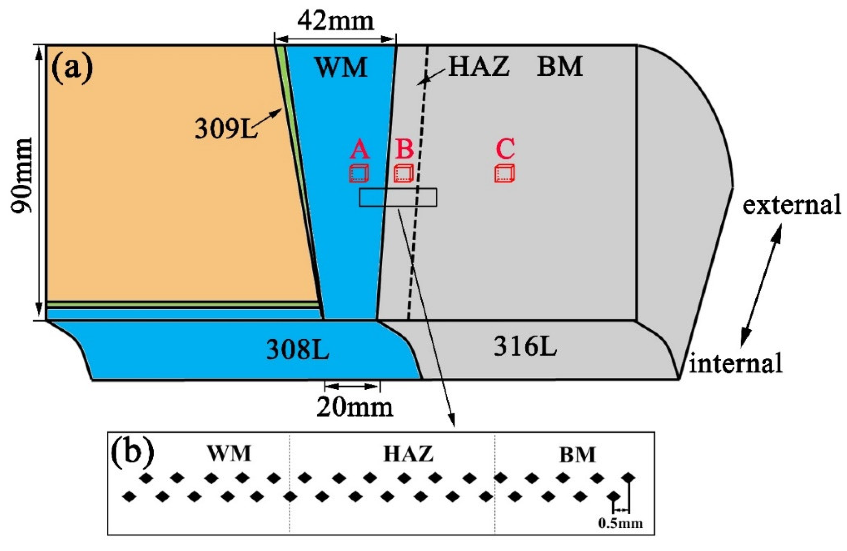
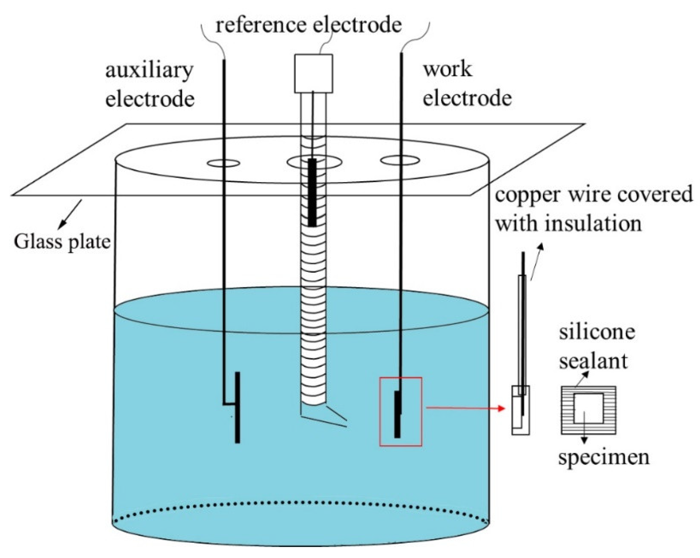
2. Materials and Methods

The welded joint used in this article was prepared by multipass and multilayer shielded metal arc welding, provided by Dongfang Electric Corporation (Guangzhou, China). It was manufactured by buttering with 308L as the WM and 316L as BM in tungsten inert gas welding. The welding was performed with a current of 350 A and a voltage of 12 V in 99.995% Ar gas. The travel speed of welding is 100 mm/min. The chemical composition of filler metal 308L and base metal (BM) 316L are Fe-17.9Cr-11Ni-0.9Mn-0.35Si-0.3C (wt.%) and Fe-20Cr-11.7Ni-2.4Mo-1.71Mn-0.52Si-0.025C (wt.%), respectively. As shown in Figure 1a, three specimens (shown by A, B, and C) were cut in WM, HAZ, and BM sections respectively, for microstructure observation. Another three specimens A, B, and C of the dimensions 5 mm × 5 mm × 2 mm, were cut in the same region for electrochemical tests. The microhardness measurements were conducted in the middle of the welded joint to distinguish HAZ from BM, as seen in Figure 1b. The microhardness across the 308L-316L interface was measured with VTD512 microhardness tester (Beijing Wowei Technology Limited Company, Beijing, China) with a load of 0.49 N and a holding time of 15 s. The distance between two measures is 0.5 mm.
For original microstructure observation, specimens for scanning electron microscope (SEM, Zeiss supra55, Zeiss, Jena, Germany) observation were grinded by silicon carbide papers with 200–2000 grit, polished by 2.5 μm diamond paste, and electroetched in a mixture with 10 wt.% oxalic acid and 90 wt.% H2O. The energy dispersive spectrometer (EDS, Zeiss, Jena, Germany) was used to analyze the distribution of chemical elements. Residual strain distribution was further analyzed with electron backscatter diffraction (EBSD, Jena) with a step size of 3.5 μm, and the data were processed with the software Channel 5 (5.12, Oxford Instruments, Oxon, UK). To characterize the residual strain, the average misorientation was calculated with a criterion that misorientations exceeding a tolerance value of 5° were excluded from calculation [1]. For EBSD, specimens were grinded and then electropolished in a mixture with 15 vol.% perchloric acid and 85 vol.% ethyl alcohol. Foils for transmission electron microscope (TEM, Tecnai G20, FEI, Hillsboro, OR, USA) were prepared from the disks with a twin-jet polisher at 50 mV in an electrolyte consisting of 95 vol% ethanol and 5 vol% perchloric acid at −30 °C.
To characterize the pitting corrosion resistance, the potentiodynamic polarization curves of different sections in the 308L-316L welded joint were analyzed. Electrochemical tests were performed in the 3.5 wt.% NaCl solution at room temperature by three-electrode cell system with the specimens as the working electrode, a saturated calomel electrode (SCE) as the reference electrode, and a platinum electrode as the auxiliary electrode. The schematic drawing of the electrochemical cells was shown in Figure 2. The specimens for electrochemical tests were grinded and then polished. The specimens were sealed in silicone sealant, and the polished surfaces were exposed as the working electrodes. The specimens were tested by continuous open-circuit potential until the potential was stable within ±1 mV. To get relatively small pits and distinguish the pit initiation sites, the potentiodynamic polarization curves were tested with the potential scan rate of 2 mV/s. After tests, the specimens were characterized with SEM to observe the corrosive surface. All electrochemical tests were performed three times to ensure repeatability. In order to analyze the distribution of pits in WM, 500 pits were observed. The specimens were processed at −1200 mVSCE for 10 min to remove the oxides formed in air by cathodic reduction. Then, to obtain dense passive and thin films at surface, specimens were anodic polarized in the 0.5 M H2SO4 solution at 400 mVSCE for 1 h. To characterize the composition of the passive films, X-ray photoelectron spectroscopy (XPS) measurements (Kratos Analytical Ltd., Manchester, UK) were taken using an Al-Kα anode X-ray source (150 W, 15 kV, and hn = 1486.6 eV).

3. Results

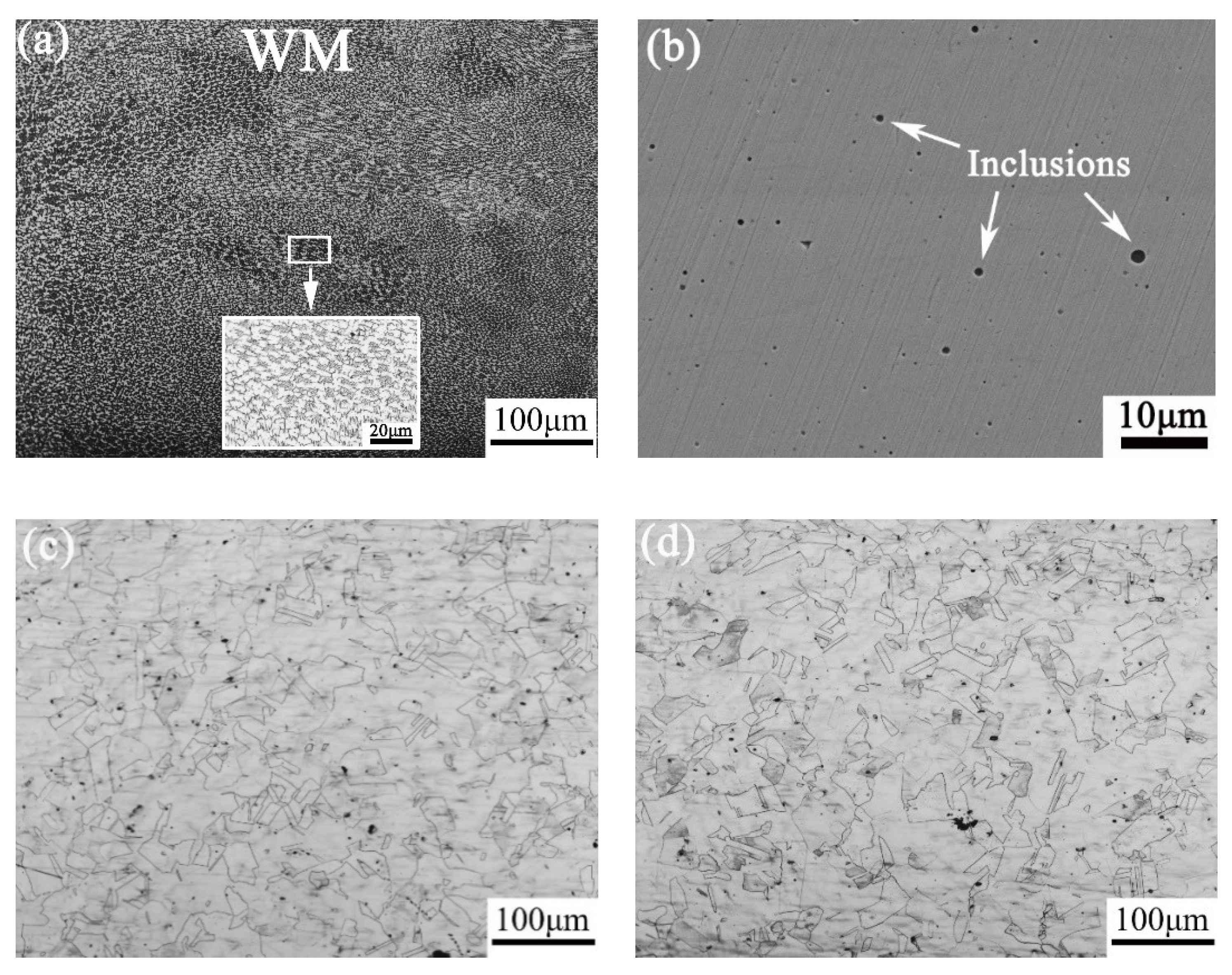
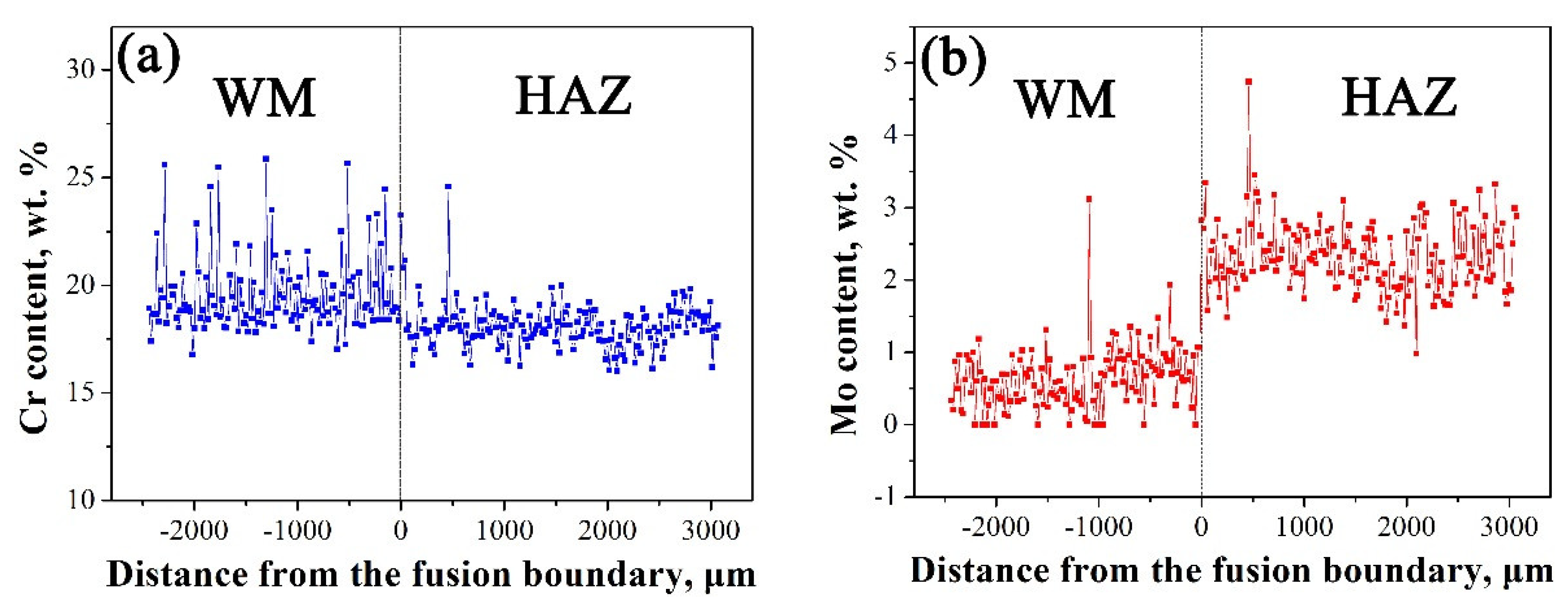
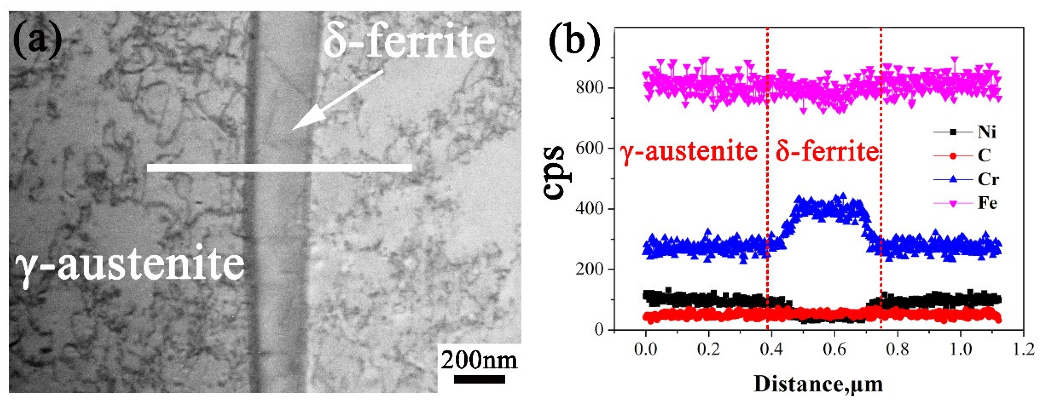
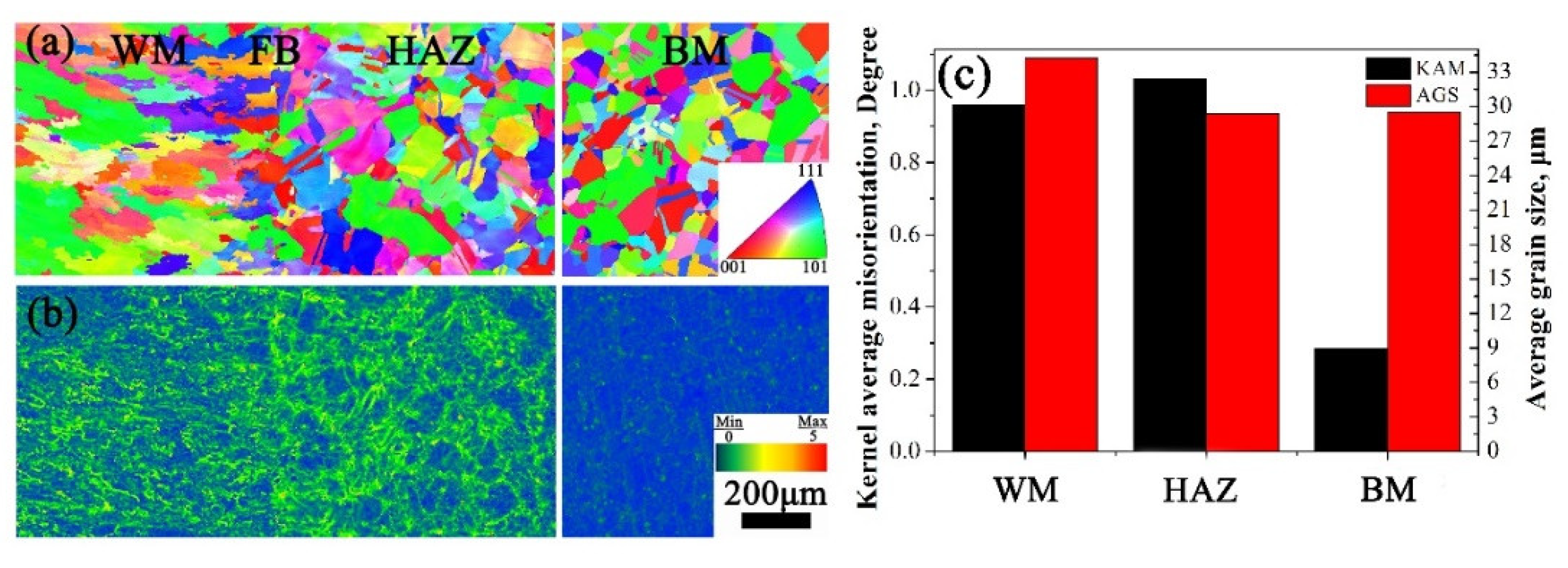
3.1. Microstructure of the 308L-316L Welded Joint

As shown in Figure 3a, WM consists of coarse grains of dendrite-like austenitic structure and skeletal δ ferrite. By doing statistical analysis, there is 13.96 vol.% δ ferrite in WM. By observing the microstructure of WM without etching in Figure 3b, there are many inclusions with a size range of 0.5–1.5 μm, which are deoxidation products during welding. By observing Figure 3c,d, we can see that both HAZ and BM consist of fine equiaxed austenite grains with annealing twins. There is no obvious change in grain size and microstructure morphology between those two regions.
Further EDS analysis shown in Figure 4 indicates that inclusions in WM are rich in Mn, Al, Si, and O and are in depletion of Cr, Fe, and Ni. It is easy to induce that the inclusions are (Mn, Al, and Si) oxides with a circular shape. The EDS line scanning curves across the welded joint is shown in Figure 5. As seen, the two sections contain similar Cr content, while there are more Mo elements in 316L than in 308L. With the increasing distance from FB, there is no obvious change on Cr and Mo contents in 316L stainless steel. Moreover, there is large fluctuation for Cr elements in WM due to the existence of δ ferrite. Further EDS line scanning with large magnification indicates that δ ferrite contains more Cr than γ austenite, as seen in Figure 6. In addition, much more dislocations tangled with each other in austenite than in ferrite are seen.
By performing EBSD, the inverse pole figure (IPF) and kernel average misorientation (KAM) distribution of the welded joint is shown in Figure 7a,b, respectively. As seen in Figure 7a, grain orientations in all sections distribute randomly. Except for austenite dendrites in WM, austenite in HAZ and BM presents as equiaxed grains and no obvious difference was observed in the two sections, which is consistent with Figure 3. On the other hand, there is much higher residual strain in WM and HAZ than in BM, as seen in Figure 7. Average grain size (AGS) and KAM value in the three sections were calculated as seen in Figure 7c. Obviously, AGS in HAZ and BM is similar, i.e., 29 μm. However, the KAM value of HAZ and WM is about 1°, which is much higher than the 0.3° of BM. According to the reference [18], the residual strain values were estimated as 7.70%, 9.96%, and 1.81% for WM, HAZ, and BM, respectively.

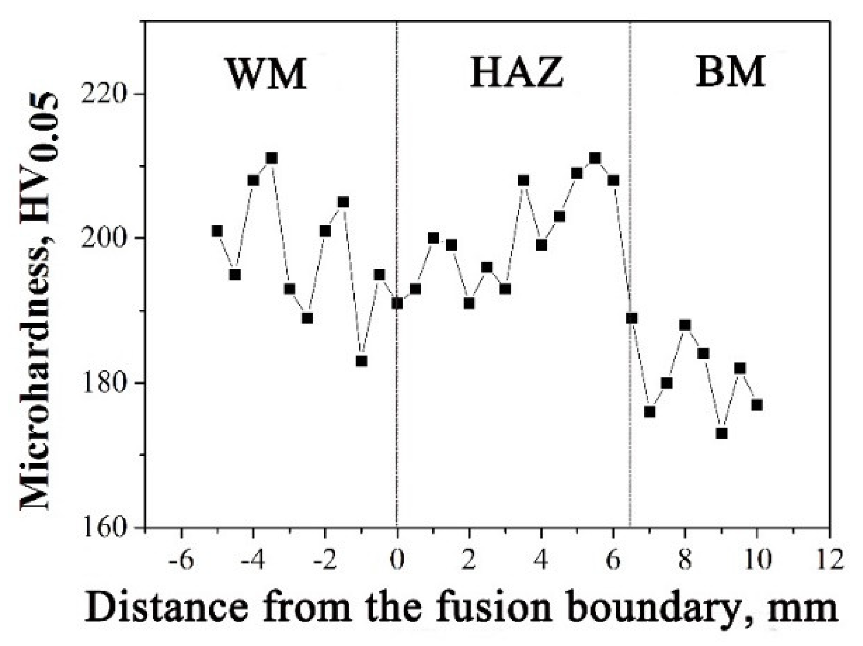
3.2. Microhardness Distribution of 308L-316L Welded Joint

Since there is no obvious microstructure difference between HAZ and BM, the microhardness distribution across the welded joint was measured to determine the HAZ region, as shown in Figure 8. As seen, the microhardness within 6.3 mm away from fusion boundary is around 200 HV, which is clearly higher than 180 HV, the microhardness of BM. Therefore, HAZ region can be distinguished. In addition, the WM also has a similar microhardness value with HAZ region, whose average microhardness is around 198 HV.

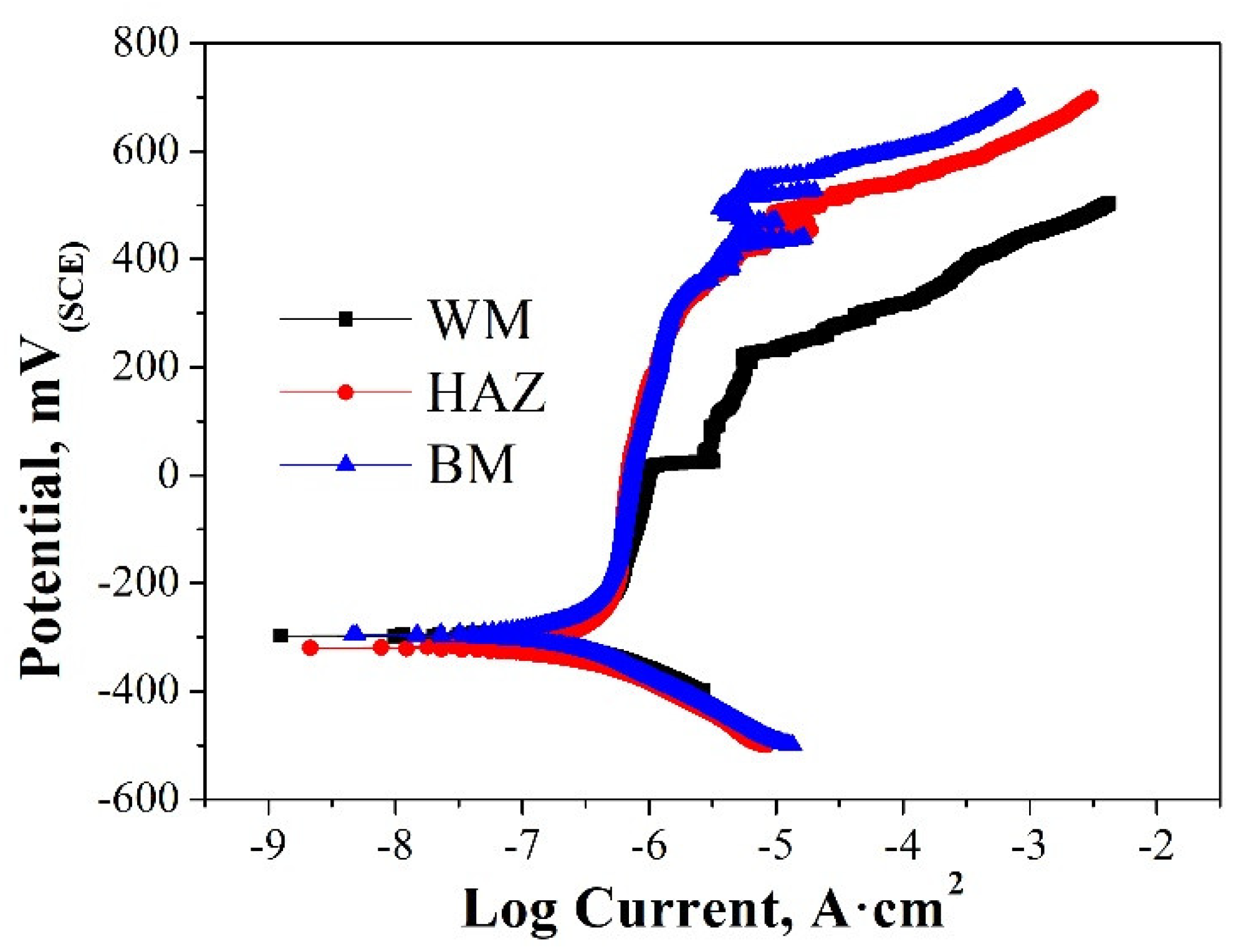
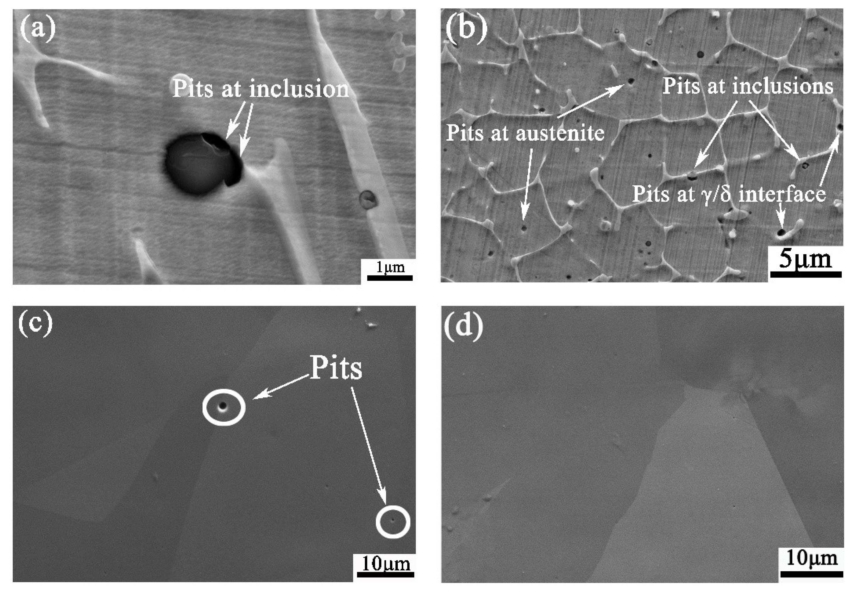
3.3. Electrochemical Test and Pitting Corrosion Morphology of 308L-316L Welded Joint

The representative set of potentiodynamic polarization curves of different sections in the 308L-316L welded joint is shown in Figure 9. By analyzing the curves, the values of corrosion potentials (Ecorr) and pitting potentials (Epit) are listed in Table 1. There is no significant difference in corrosion potential (Ecorr) among the three sections. Epit represents the resistance of pitting corrosion. The higher the value, the higher the pitting corrosion resistance. As seen, the high-to-low order of pitting potentials is Epit (BM) > Epit (HAZ) > Epit (WM). Apparently, the WM is the most critical section for pitting corrosion in the welded joint.
The morphologies of different sections after potentiodynamic polarization tests are shown in Figure 10. Apparently, there are the most pits in WM, and the least pits in BM, which is in tune with the results of electrochemical tests. It can also be found that there are pits at inclusions, austenite, and the interface between austenite and ferrite in WM. By statistical analysis with 500 pits in WM, 53.8% pits initiate at inclusions, 23.2% at δ/γ interface, and 23% in austenite. In 316 HAZ section, the pits observed are in austenite.

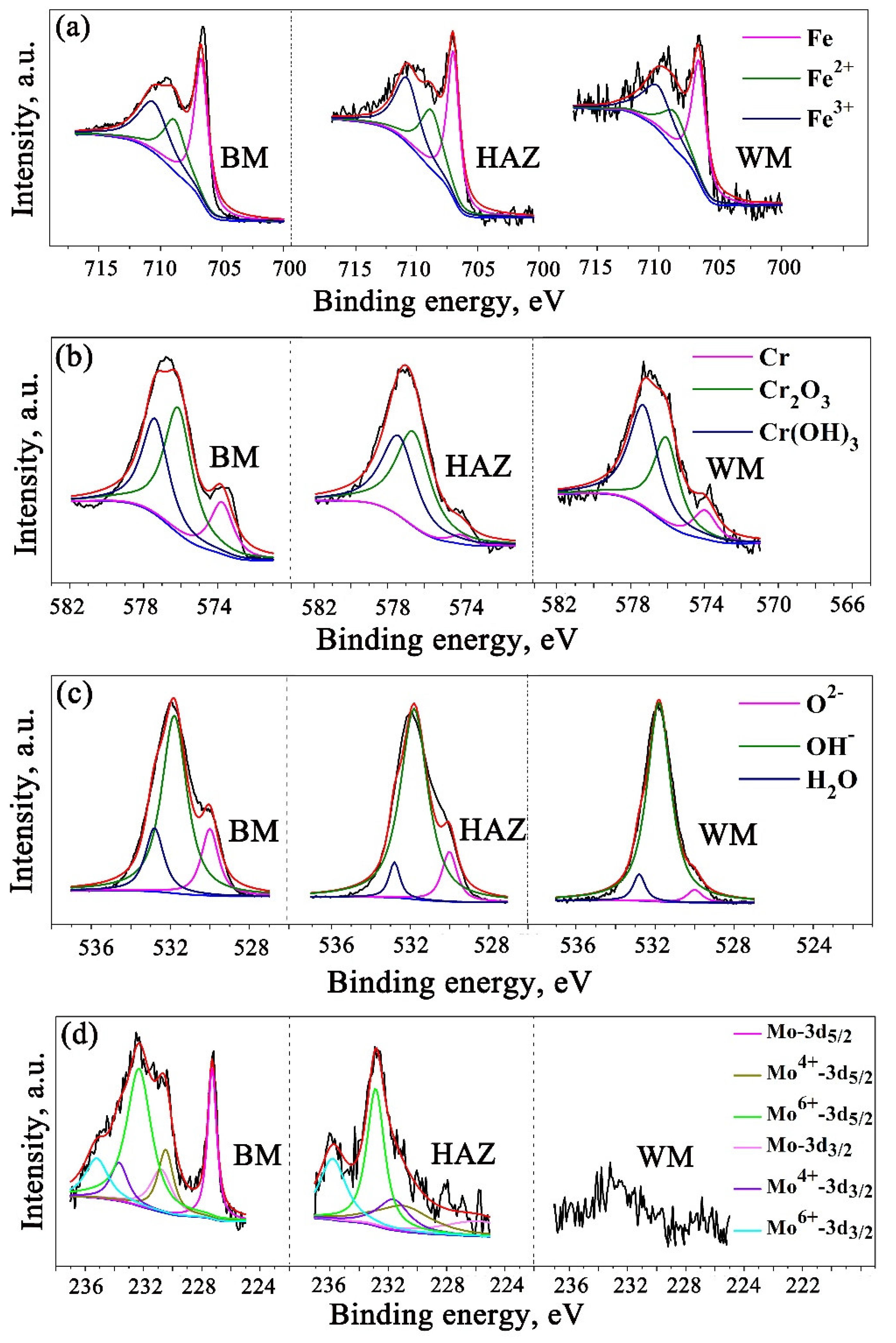
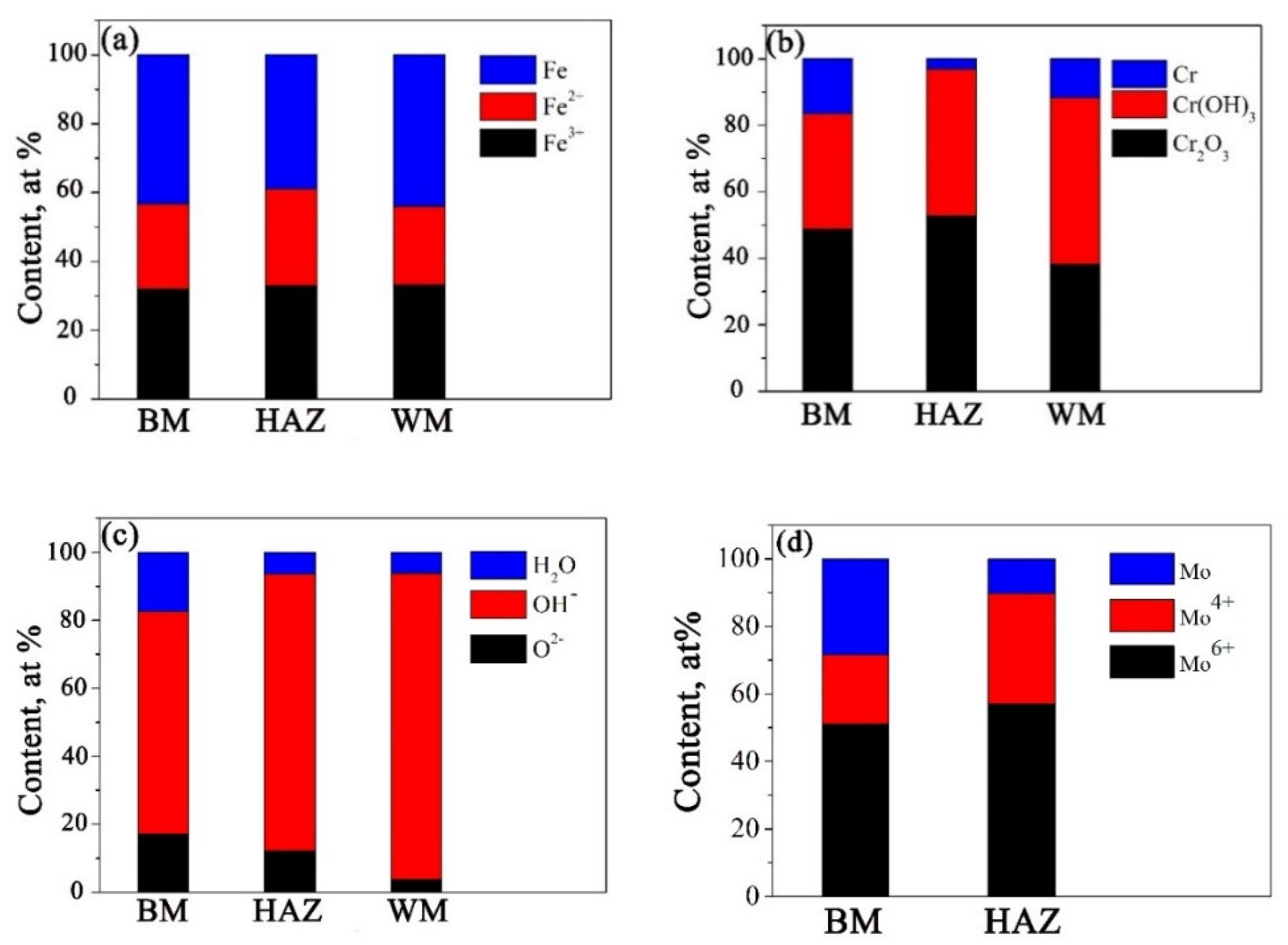
3.4. XPS Analysis of 308L-316L Welded Joint

The pitting resistance of stainless steel is closely related to composition and structure of passive film on their surface. In this study, XPS was used to analyze the passive film and the results are shown in Figure 11. The spectra of the Fe2p3/2, Cr2p3/2, O1s, and Mo 3d were evaluated using the parameters of standard peaks [19,20,21]. According to the binding energy, Fe2p3/2 peak can be decomposed into the Fe2+ at 708.4 eV, Fe3+ at 710.8 eV, and Fe0 at 707 eV and Cr 2p3/2 into the Cr3+ in Cr2O3 at 576.6 eV, Cr3+ in Cr(OH)3 at 577.4 eV, and Cr0 at 574 eV [19]. Mo 3d spectra were detected in both BM and HAZ section, while it was almost invisible in WM. Since Mo 3d5/2 and Mo 3d3/2 were difficult to be decomposed, six overlapping components were deconvoluted to Mo 3d5/2 at 227.4 eV, Mo4+ 3d5/2 at 230.2 eV, Mo6+ 3d5/2 at 232.2 eV, Mo 3d3/2 at 230.9 eV, Mo4+ 3d3/2 at 233.4 eV, and Mo6+ 3d3/2 at 234.1 eV [22].
The fraction of (a) Fe, (b) Cr, (c) O, and (d) Mo species in passive films in different sections were analyzed according to Figure 11. As shown in Figure 12, there is no obvious difference for Fe species among BM, HAZ, and WM. In addition, Cr2O3 content in both HAZ and BM sections is ~50%, which is much higher than that in WM. The high-to-low order of Cr(OH)3 content in different sections is WM > HAZ > BM. Moreover, Mo6+ is the primary component of Mo species in BM and HAZ. It is very likely that Mo6+ formed MoO42− and Mo4+ formed MoO2 since no other negative ions combing Mo can form during the test.

4. Discussion

By analyzing Epit value and pitting corrosion morphology, the WM is the most critical section for pitting corrosion for the 308L-316L welded joint. First, the passive film formed in WM is inhomogeneous. As stated above, 53.8% pits initiate at inclusions, 23.2% at δ/γ interface, and 23% in austenite in WM. Those inclusions have been identified as (Mn, Al, and Si) oxides, which are Cr-depleted, as shown in Figure 4. As a result, weak passivation films containing few protective Cr2O3 are easy to be broken under action of Cl ions. In addition, some pits also initiated at the δ/γ interface. According to the reference [3], there are some Cr-depleted carbides at the δ/γ interface, which are prone to have pits. Many studies have illustrated that a small amount of δ ferrite will improve the hot cracking resistance of austenitic stainless steel [8,9,10]. Yet more than 5 vol.% δ ferrite will deteriorate the pitting corrosion resistance [11]. The WM contains 13.96 vol.% δ ferrite, and continuous network ferrite further reduces the corrosion resistance of the steel [11]. The last but not least, some pits nucleate in austenite, which can be attributed to less Cr content and lots of dislocations, as seen in Figure 6.
Moreover, the passive film in WM is relatively instable, compared with that in HAZ and BM. The passive films of stainless steel consist of inner oxide layer and outer oxide particles. The inner oxide layer composed of Fe2O3 and Cr2O3 is critical to the corrosion resistance of stainless steel [23]. The outer hydroxides including Cr(OH)3 and FeOOH are easy to be penetrated and unprotective [13]. Cr2O3, Fe2O3, and FeO are main erosion-resisting oxides with O2− [23]. As seen in Figure 12, there are more OH and less O2− in WM than in HAZ and BM. This illustrates less Fe2O3 and Cr2O3 existing in WM. As a result, the passive film is unstable. Furthermore, the WM contains less Mo. Mo existed in passivation film with different forms, contributing to the pitting resistance. For instance, MoO42− with Mo6+ prevents Cl ion from accumulating on the passivated metal surface [24]. In addition, MoO2 with Mo4+ can also increase the stability of passivation film [25].
As discussed before, the HAZ is more susceptible for pitting corrosion than 316L BM since the Epit value is lower than the BM, as shown in Figure 9 and Table 1. Even though there is no obvious difference for microstructure distribution, AGS, and chemical composition between the HAZ and BM, the rapid cooling process after welding causes residual strain in the HAZ, as shown in Figure 7. The existence of residual stress accompanied by the residual strain makes Cl ions migrate along the stress gradient easily [26], which limits the repassivation of stainless steel. In consequence, Cl ions concentration induced by residual strain in HAZ promotes pitting corrosion. This is consistent with the phenomenon that pit density grows with the increased residual stress observed by Boven et al. [27].
According to above discussion, the schematic illustration of passivation film on the surface of 308L-316L welded joint is shown in Figure 13. The passive film is inhomogeneous for WM since Cr-depleted oxide inclusions, ferrite, and carbides at the interface lead to less protective inner layer oxides such as Cr2O3. In addition, the passive film in WM is also unstable. This is because the residual strain promotes Cl ions concentration and there is less Mo content, which can stabilize the passive film. Moreover, the residual strain in HAZ also promotes its pitting corrosion susceptibility, compared with the BM.

5. Conclusions

In this work, pitting corrosion behavior of a 308L-316L welded joint was analyzed and the following conclusions can be summed up:
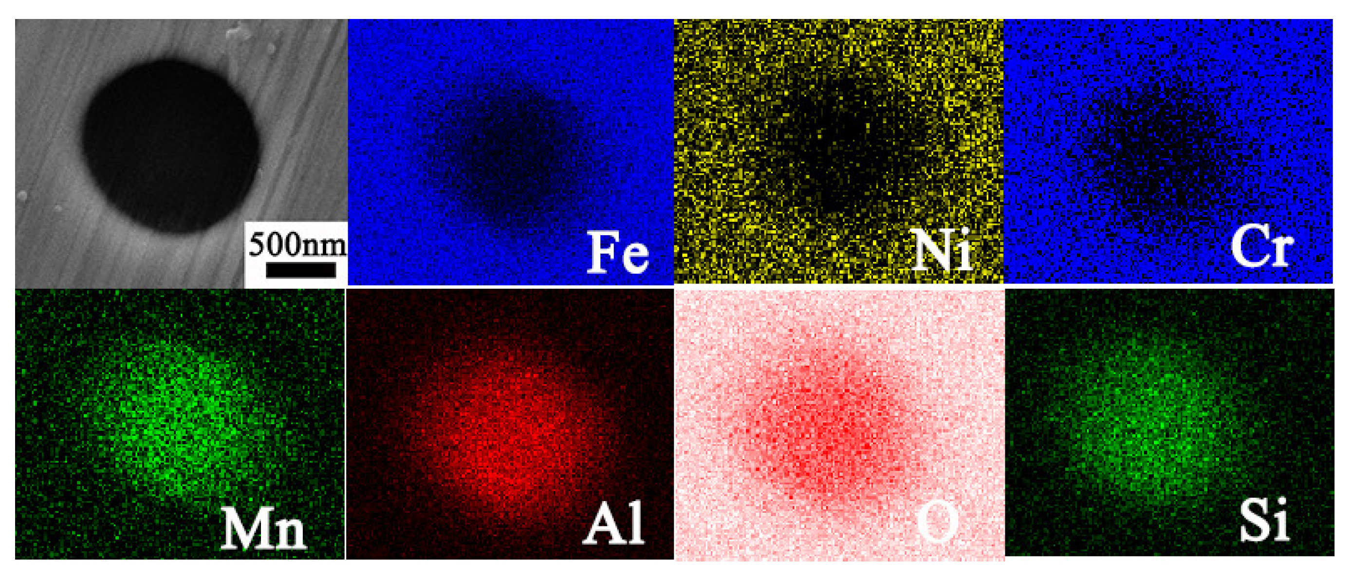
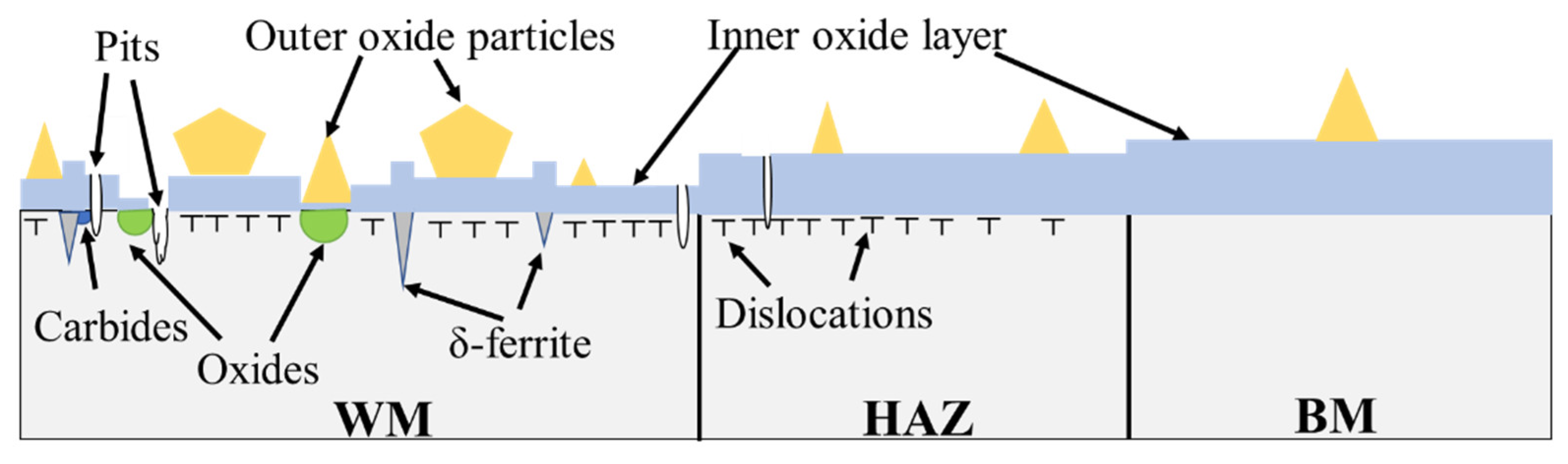
  • WM is the most vulnerable for pits to initiate in the 308L-316L welded joint. By statistical study, there are 53.8% pits initiating at Mn, Al, and Si oxides, 23.0% in austenite, and 23.2% at interface between ferrite and austenite.
  • The passive film is inhomogeneous due to lots of Cr-depleted zones such as Mn, Al, and Si oxides, carbides at interface, and austenite. It is also unstable owing to few Mo content and large residual strain.
  • HAZ is slightly easier for pits corrosion, compared with the BM even though austenite distribution in the two sections is similar. This is because the residual strain in HAZ is estimated to be 9.96%, about five times higher than the BM, which accelerates the concentration of Cl ion and promotes pitting corrosion.

Author Contributions

J.H.: conceptualization, methodology, writing original draft, and project administration. S.X.: writing original draft and investigation. W.T.: reviewing and editing. Y.H.: reviewing and editing. J.M.: reviewing and editing. X.W.: supervision and project administration. All authors have read and agreed to the published version of the manuscript.

Funding

This research received no external funding.

Conflicts of Interest

The authors declare no conflict of interest.

References

  1. Ma, C.; Peng, Q.; Mei, J.; Han, E.-H.; Ke, W. Microstructure and corrosion behavior of the heat affected zone of a stainless steel 308L-316L weld joint. J. Mater. Sci. Technol. 2018, 34, 1823–1834. [Google Scholar] [CrossRef]
  2. Ming, H.; Zhang, Z.; Wang, J.; Han, E.-H.; Ke, W. Microstructural characterization of an SA508–309L/308L–316L domestic dissimilar metal welded safe-end joint. Mater. Charact. 2014, 97, 101–115. [Google Scholar] [CrossRef]
  3. Dong, L.; Ma, C.; Peng, Q.; Han, E.-H.; Ke, W. Microstructure and stress corrosion cracking of a SA508-309L/308L-316L dissimilar metal weld joint in primary pressurized water reactor environment. J. Mater. Sci. Technol. 2020, 40, 1–14. [Google Scholar] [CrossRef]
  4. Haruna, T.; Toyota, R.; Shibata, T. The effect of potential on initiation and propagation of stress corrosion cracks for type 304l stainless steel in a chloride solution containing thiosulfate. Corros. Sci. 1997, 39, 1873–1882. [Google Scholar] [CrossRef]
  5. Dong, L.; Peng, Q.; Han, E.-H.; Ke, W.; Wang, L. Stress corrosion cracking in the heat affected zone of a stainless steel 308L-316L weld joint in primary water. Corros. Sci. 2016, 107, 172–181. [Google Scholar] [CrossRef]
  6. Zhang, Z.; Jing, H.; Xu, L.; Han, Y.; Zhao, L.; Zhang, J. Influence of microstructure and elemental partitioning on pitting corrosion resistance of duplex stainless steel welding joints. Appl. Surf. Sci. 2017, 394, 297–314. [Google Scholar] [CrossRef]
  7. Cui, Y.; Lundin, C.D. Evaluation of initial corrosion location in E316L austenitic stainless steel weld metals. Mater. Lett. 2005, 59, 1542–1546. [Google Scholar] [CrossRef]
  8. Han, L.; Guobiao, L.; Zidong, W.; Hong, Z.; Feng, L. Study on Corrosion Resistance of 316L Stainless Steel Welded Joint. Rare Met. Mater. Eng. 2010, 39, 393–396. [Google Scholar]
  9. Patchett, B.; Bringas, J. The Metals Blue Book. Filler Metals; CASTI Publishing Inc. And American Welding Society (AWS): Edmonton, AB, Canada, 1998. [Google Scholar]
  10. Lo, I.H.; Tsai, W.T. Effect of heat treatment on the precipitation and pitting corrosion behavior of 347 SS weld overlay. Mater. Sci. Eng. A 2003, 355, 137–143. [Google Scholar] [CrossRef]
  11. Sui, G.; Charles, E.A.; Congleton, J. The effect of delta-ferrite content on the stress corrosion cracking of austenitic stainless steels in a sulphate solution. Corros. Sci. 1996, 38, 687–703. [Google Scholar] [CrossRef]
  12. Ida, N.; Muto, I.; Sugawara, Y.; Hara, N. Local Electrochemistry and In Situ Microscopy of Pitting at Sensitized Grain Boundary of Type 304 Stainless Steel in NaCl Solution. J. Electrochem. Soc. 2017, 164, C779–C787. [Google Scholar] [CrossRef]
  13. Ryan, M.P.; Williams, D.E.; Chater, R.J.; Hutton, B.M.; McPhail, D.S. Why stainless steel corrodes. Nature 2002, 415, 770–774. [Google Scholar] [CrossRef] [PubMed]
  14. Es-Souni, M.; Beaven, P.A. Microanalysis of inclusion/matrix interfaces in weld metals. Surf. Interface Anal. 1990, 16, 504–509. [Google Scholar] [CrossRef]
  15. Jegdić, B.; Bobić, B.; Radojković, B.; Alić, B.; Radovanović, L. Corrosion resistance of welded joints of X5CrNi18-10 stainless steel. J. Mater. Process. Technol. 2019, 266, 579–587. [Google Scholar] [CrossRef]
  16. Chu, T.; Nuli, Y.; Cui, H.; Lu, F. Pitting behavior of welded joint and the role of carbon ring in improving corrosion resistance. Mater. Des. 2019, 183, 108120. [Google Scholar] [CrossRef]
  17. Malhotra, D.; Shahi, A.S. Metallurgical, Fatigue and Pitting Corrosion Behavior of AISI 316 Joints Welded with Nb-Based Stabilized Steel Filler. Met. Mater. Trans. A Phys. Met. Mater. Sci. 2020, 51, 1647–1664. [Google Scholar] [CrossRef]
  18. Kamaya, M. Measurement of local plastic strain distribution of stainless steel by electron backscatter diffraction. Mater. Charact. 2009, 60, 125–132. [Google Scholar] [CrossRef]
  19. Ming, H.L.; Zhang, Z.M.; Wang, S.Y.; Wang, J.Q.; Han, E.H.; Ke, W. Short time oxidation behavior of 308L weld metal and 316L stainless steel with different surface state in simulated primary water with 0.1 mg/L dissolved oxygen. Mater. Corros. 2015, 66, 869–881. [Google Scholar] [CrossRef]
  20. Ma, C.; Han, E.-H.; Peng, Q.; Ke, W. Effect of polishing process on corrosion behavior of 308L stainless steel in high temperature water. Appl. Surf. Sci. 2018, 442, 423–436. [Google Scholar] [CrossRef]
  21. Kong, X.; Qiao, Y. Crack trapping effect of persistent grain boundary islands. Fatigue Fract. Eng. Mater. Struct. 2005, 28, 753–758. [Google Scholar] [CrossRef]
  22. Liu, C.T.; Wu, J.K. Influence of pH on the passivation behavior of 254SMO stainless steel in 3.5% NaCl solution. Corros. Sci. 2007, 49, 2198–2209. [Google Scholar] [CrossRef]
  23. Chen, X.; Li, Y.; Zhu, Y.; Bai, Y.; Yang, B. Improved corrosion resistance of 316LN stainless steel performed by rotationally accelerated shot peening. Appl. Surf. Sci. 2019, 481, 1305–1312. [Google Scholar] [CrossRef]
  24. Ilevbare, G.O.; Burstein, G.T. The inhibition of pitting corrosion of stainless steels by chromate and molybdate ions. Corros. Sci. 2003, 45, 1545–1569. [Google Scholar] [CrossRef]
  25. Kuczynska-Wydorska, M.; Flis-Kabulska, I.; Flis, J. Corrosion of low-temperature nitrided molybdenum-bearing stainless steels. Corros. Sci. 2011, 53, 1762–1769. [Google Scholar] [CrossRef]
  26. Reddy, G.M.; Rao, K.S.; Sekhar, T. Joining. Microstructure and pitting corrosion of similar and dissimilar stainless steel welds. Sci. Technol. Weld. Join. 2008, 13, 363–377. [Google Scholar] [CrossRef]
  27. Boven, G.V.; Chen, W.; Rogge, R. The role of residual stress in neutral pH stress corrosion cracking of pipeline steels. Part I: Pitting and cracking occurrence. Acta Mater. 2007, 55, 29–42. [Google Scholar]
Figure 1. Schematic drawing showing (a) the geometry of the 308L-316L welded joint and (b) the distribution of microhardness points.
Metals 10 01258 g001
Figure 2. Schematic drawing of the electrochemical cells.
Metals 10 01258 g002
Figure 3. Microstructure of (a) weld metal (WM) with etching, (b) WM without etching, (c) heat-affected zone (HAZ), and (d) base metal (BM).
Metals 10 01258 g003
Figure 4. EDS surface scanning of inclusion in WM.
Metals 10 01258 g004
Figure 5. EDS line scanning curves across 308L-316L interface: (a) Cr and (b) Mo.
Metals 10 01258 g005
Figure 6. (a) TEM morphology and (b) EDS analysis across ferrite and austenite.
Metals 10 01258 g006
Figure 7. (a) Inverse pole figure (IPF), (b) kernel average misorientation (KAM) maps, and (c) statistical information in different section of the 308L-316L welded joint.
Metals 10 01258 g007
Figure 8. Microhardness distribution of the 308L-316L welded joint.
Metals 10 01258 g008
Figure 9. Potentiodynamic polarization curves of different sections in the 308L-316L welded joint.
Metals 10 01258 g009
Figure 10. Local corrosion morphologies for (a) and (b) 308L WM, (c) 316L HAZ, and (d) 316L BM.
Metals 10 01258 g010
Figure 11. XPS spectra of (a) Fe 2p3/2, (b) Cr 2p3/2, (c) O 1s, and (d) Mo 3d in the passive film formed on BM, HAZ, and WM.
Metals 10 01258 g011
Figure 12. The fraction of (a) Fe, (b) Cr, (c) O, and (d) Mo species in passive films in different sections.
Metals 10 01258 g012
Figure 13. Schematic illustration of the passivation film on the surface of 308L-316L welded joint.
Metals 10 01258 g013
Table 1. Corrosion and pitting potentials of the 308L-316L welded joint in the 3.5 wt.% NaCl solution.
SectionEcorr (mVSCE)Epit (mVSCE)
WM−299 ± 35217 ± 77
HAZ−319 ± 4485 ± 23
BM−295 ± 9545 ± 12

