Article

Effects of Laser Melting Distribution on Wear Resistance and Fatigue Resistance of Gray Cast Iron

1
College of Automotive Engineering, Jilin University, Changchun 130025, China
2
School of Mechanical Science and Aerospace Engineering, Jilin University, Changchun 130025, China
3
College of Material Science and Engineering, Jilin University, Changchun 130025, China
*
Author to whom correspondence should be addressed.
Metals 2020, 10(9), 1257; https://doi.org/10.3390/met10091257
Submission received: 6 July 2020 / Revised: 11 September 2020 / Accepted: 14 September 2020 / Published: 17 September 2020
(This article belongs to the Special Issue Advances in Laser Materials Processing)

Abstract

:
The coupling bionic surface is generally prepared by laser melting on the surface of a gray iron brake hub, which can allow the brake hub to achieve excellent wear resistance and fatigue resistance. The designs of most previous experiments have been based on independent units that were uniform in their distribution patterns. Although some progress has been made in the optimization of cell features, there is still room for further improvement with respect to bionics and experimental optimization methods. Here, experiments on units with non-uniform distributions of different distances were used to rearrange and combine the bionic elements. This paper is that the original uniform distribution laser melting strengthening model was designed as a non-uniform distribution model, and the heat preservation and tempering strengthening effect of continuous multiple melting strengthening on the microstructure of the melting zone is discussed. The mechanism of crack initiation and the mode of crack propagation were analyzed. The relationship between the internal stress in the melting zone and the crack initiation resistance was also discussed. In this paper, the mechanism of different spacing distribution on the surface of gray cast iron by laser remelting is put forward innovatively and verified by experiments, which provides a solid theoretical basis for the follow-up industrial application.

1. Introduction

Results have shown that the base metal on the brake drum surface of gray cast iron may be melted rapidly by laser technology. This can change the structure of the brake drum base metal, refine the grain, and greatly improve hardness, strength, and toughness [1,2,3]. By imitating the biological characteristics of organisms that exist in nature that show excellent wear and fatigue resistance [4,5], a bionic functional surface similar to the surface of such organisms can be fabricated by applying a laser to the inner wall of a gray cast iron brake drum [6,7]. The structure of the base metal of the brake drum can be irradiated by a laser [8,9], causing it to melt rapidly and then solidify again instantaneously [10]. The new structure obtained has a strength and toughness far beyond that of the gray cast iron base metal [11,12]. The locus of the melted structure is distributed on the inner surface of the brake drum with a certain shape [13,14]. Thus, the hard unit and the base metal are combined to form a soft/hard interphase bionic surface composed of different structures and shapes. Previous test results showed that the hard element embedded in the matrix has a “dike” and “nail pile” effect [15,16]. This hard element can effectively prevent the growth of cracks in the brake drum, reduce the growth rate of surface cracks in the gray cast iron, and improve the service life of the brake drum.
The experiments conducted in this study attempted to address human needs by learning and applying the mechanisms and laws of the biological world that have been discovered by the application of the bionics principle [17,18]. The phenomenon of biological coupling is an inherent property of living things that has increased the vitality of organisms throughout their evolutionary history. The researchers in this study found that the ability of natural organisms to adapt to their environment did not simply involve changes in a single factor; instead, this adaptability resulted from the synergy of two or more different parts or the coupling of different factors. Some examples of this adaptability include the self-cleaning function of the leaves of plants such as the lotus leaf and reed and the anti-sticking property exhibited by the wings of insects such as the night moth [19,20]. These functionalities are all realized by the coupling of various factors such as the non-smooth shape of a surface or the micro/nanocomposite structure of low-energy materials. For example, the non-smooth hard scales on the backs of lizards, rock lizards, and scorpions are coupled with multiple layers of flexible connective tissue that lie just under the skin, which allows these species to have excellent resistance to erosion in desert environments. The excellent wear resistance of conch and other seashells depends on the coupling of non-smooth composite morphology, multilayer structures, and special materials [21,22].
Similarity science points out that the principles of certain biological structures and functions can be used to construct technical systems and make the characteristics of these technical systems like those of biological systems. The systems formed have functions that are like those of the original system. The surface structures of organisms with excellent wear resistance and fatigue resistance share many similar characteristics [23]. First, they all have alternating structures made up of hard and soft elements. The distribution of hard elements can take various forms. The relatively high degree of hardness of the hard elements comes from the difference in structure or material between the hard and soft elements. The coupling of morphology, structure, and material gives such surfaces excellent wear resistance and fatigue resistance. The properties of a surface comprising soft phases and hard phases can be brought fully into play in biology [24]. The hard phase structure can play a supporting role by, for example, preventing crack initiation and propagation; in addition, this structure can improve the wear resistance of materials. According to the principle of biological coupling, the bionic coupling wear-resistant and thermal fatigue-resistant model is a type of hard element with certain shapes distributed on the soft base metal. This hard element derives different microstructural or constituent materials from the soft base metal, and the two constitute a structure with soft and hard intersections [25]. Coupling bionic wear-resistance and anti-fatigue properties has been proposed as a way to theoretically solve the problem of part failure caused by fatigue and wear on the surface of materials and engineering application problems such as surface adhesion and drag reduction.
Much research and achievements in applications of bionic coupling wear-resistance and fatigue resistance have been made using laser treatment [26]. Laser technology also has a lot of applications in the surface strengthening of alloy parts. Qiuyue Su et al. studied the influence of nano layer depth etched by femtosecond and nanosecond laser on the precision of resistance modulation [27]. This method is applied to wear-resistant parts under various working conditions. The hard phases are processed on their parent bodies by laser melting or cladding. These hard phases and the parent bodies form different types of soft and hard interphase structures on the surface of the parts, replacing the original surface and greatly improving their thermal fatigue resistance, wear-resistant performance, and the service life of the parts. According to the principle of biological coupling, different functions can be obtained by different coupling and factor combinations, and different functional requirements can be obtained by changing the parameters of each coupling element to form corresponding models [28]. All these studies are based on the experimental optimization design of various bionic coupling models, which are composed of coupling elements that include various shapes, structures, and materials. After the effects of different coupling bionic treatments on the thermal fatigue resistance and wear resistance of materials are determined, they can be applied to each wear-resistant component to improve the service life of components [29].
The application of coupled biomimetic theory has achieved many breakthroughs in terms of wear resistance and fatigue resistance. However, in the process of biomimetic model design, research has primarily been based on a single type of spacing [30]. Although the performance achieved by the biomimetic model depends on the characteristic parameters of the coupling element, the spacing distribution of the unit always maintains an average distribution [31]. In nature, the non-uniform distribution of various bio-coupling elements on the surface of organisms can further improve the performance of organisms by enhancing their ability to cope with more complex biological environments. In the process of braking, the surface of the brake drum is constantly subjected to tension and compression stress in the process of brake pad wear [32]. At the same time, because of the large amount of heat generated in the process of friction, the interior of the brake drum is constantly subjected to the internal stress transformations caused by the alternation of cold and hot temperatures. Therefore, the fatigue failure and crack growth mode of the brake drum represent locally concentrated non-uniform sudden changes in growth. This study designed a coupling bionic model of the surface of a non-uniform gray cast iron brake drum to further enhance the reliability of the wear-resistance and anti-fatigue characteristics of the bionic brake drum. In this paper, based on the above research, the uniform distribution of the bionic surface was designed as a non-uniform distribution. The microstructure and internal stress of laser melting changed from discontinuous processing to continuous processing of the local area. Therefore, the wear resistance and fatigue resistance of the non-uniform distribution bionic surface also change correspondingly. This paper hopes to further optimize the wear resistance and fatigue resistance of the gray iron coupling bionic surface and provide a more practical model. The model that we designed used a different combination of multiple units rather than a single unit to enhance the wear-resistance and anti-fatigue properties [33].

2. Experimental

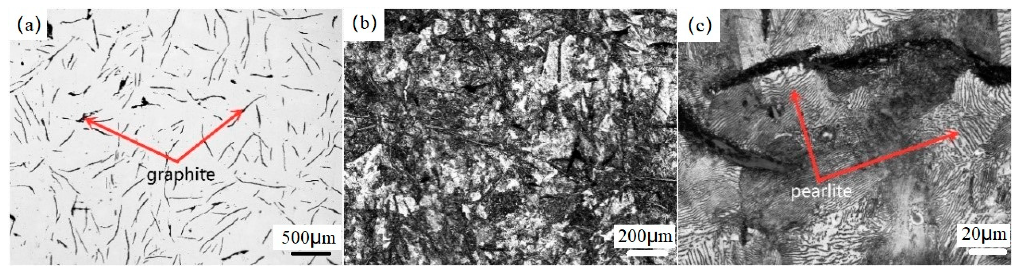
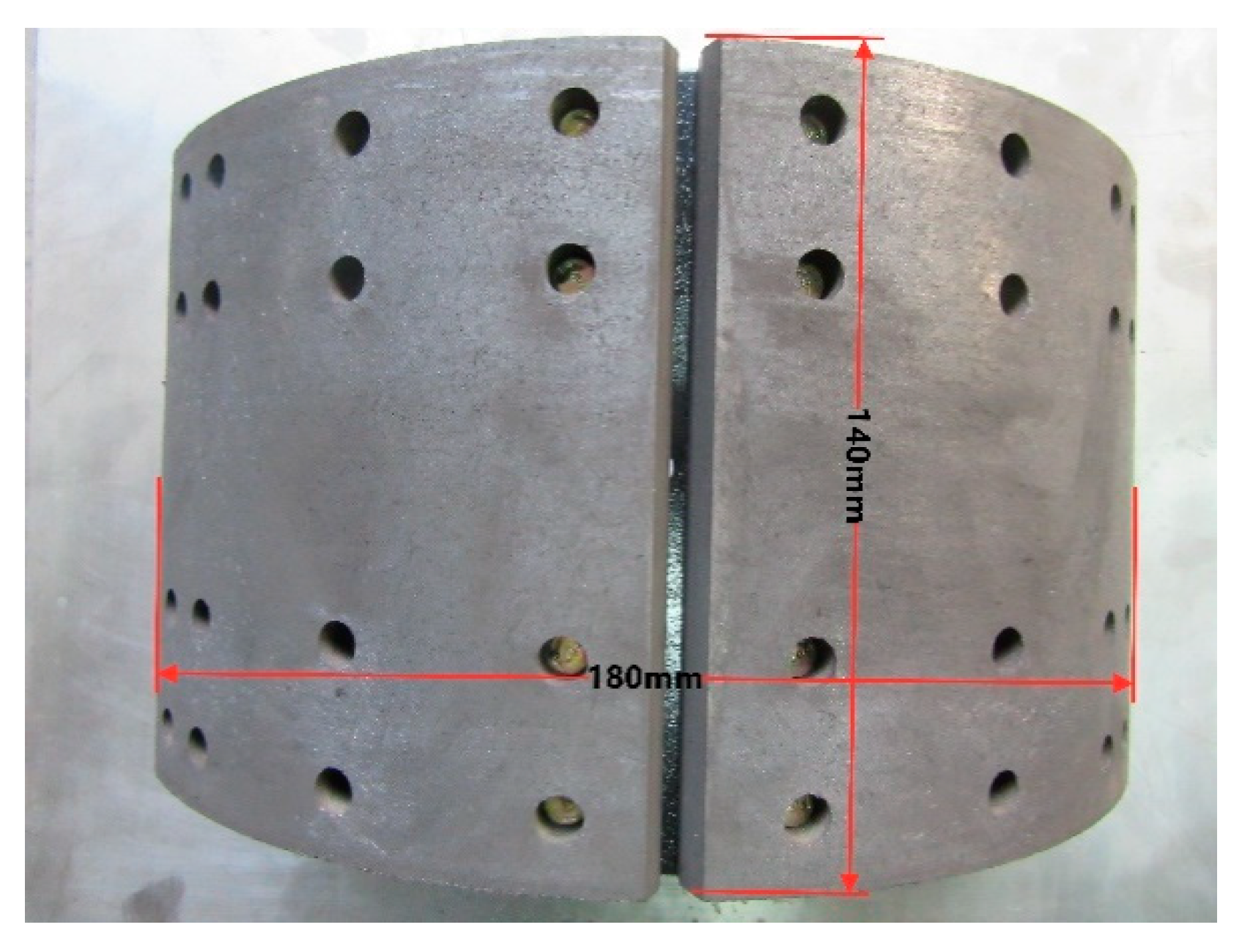
2.1. Experiment Materials

The cast iron used in the experiment was cut from the brake drum of a heavy truck provided by the First Automotive Work shop Group in China. The cast iron brand of the brake drum production was HT250, and the structure of cast iron material is shown in Figure 1. The graphite type contained a small amount of type B flake graphite (see Figure 1a); the matrix structure was pearlite (more than 90%) + a small amount of ferrite (see Figure 1b,c); and the main chemical composition is shown in Table 1.
The wear pair selected for this test was a pair of brake pads commonly used in the brake drum of heavy trucks—semi-metallic brake pads—as shown in Figure 2

2.2. Experimental Method

In this experiment, a brake hub manufactured by the FAW casting company was studied where the brake hub was destroyed, and the sample was prepared. Striped biomimetic samples were used in the experiments as previous research has shown that striped biomimetic samples have better performance/price ratios. The coupling bionic specimen with a non-uniform distribution described in this paper is shown in Figure 3. This was designed as a model with either a two, three, or four parallel offset distribution of a biomimetic unit. Each model in this paper was defined as P2, P3, and P4, and the average distribution of a single cell was defined as P1. To ensure the robustness of the tests, the total number of units on the same sample and the distribution/area ratio between the unit and the parent remained unchanged. Each unit–body combination was arranged in strips with a spacing of 2.4 mm, 3.6 mm, and 4.8 mm. After the design was complete, the laser melting method was used to complete the processing. Thermal fatigue tests were conducted on different unit combinations, and the wear tests were conducted under different thermal fatigue times. The thermal fatigue wear characteristics of different coupled bionic models were studied. Finally, the corresponding model was adjusted based on the wear and fatigue of the brake hub occurring during actual use, and the adjusted and optimized model was retested to verify that the adjustment improved the model.

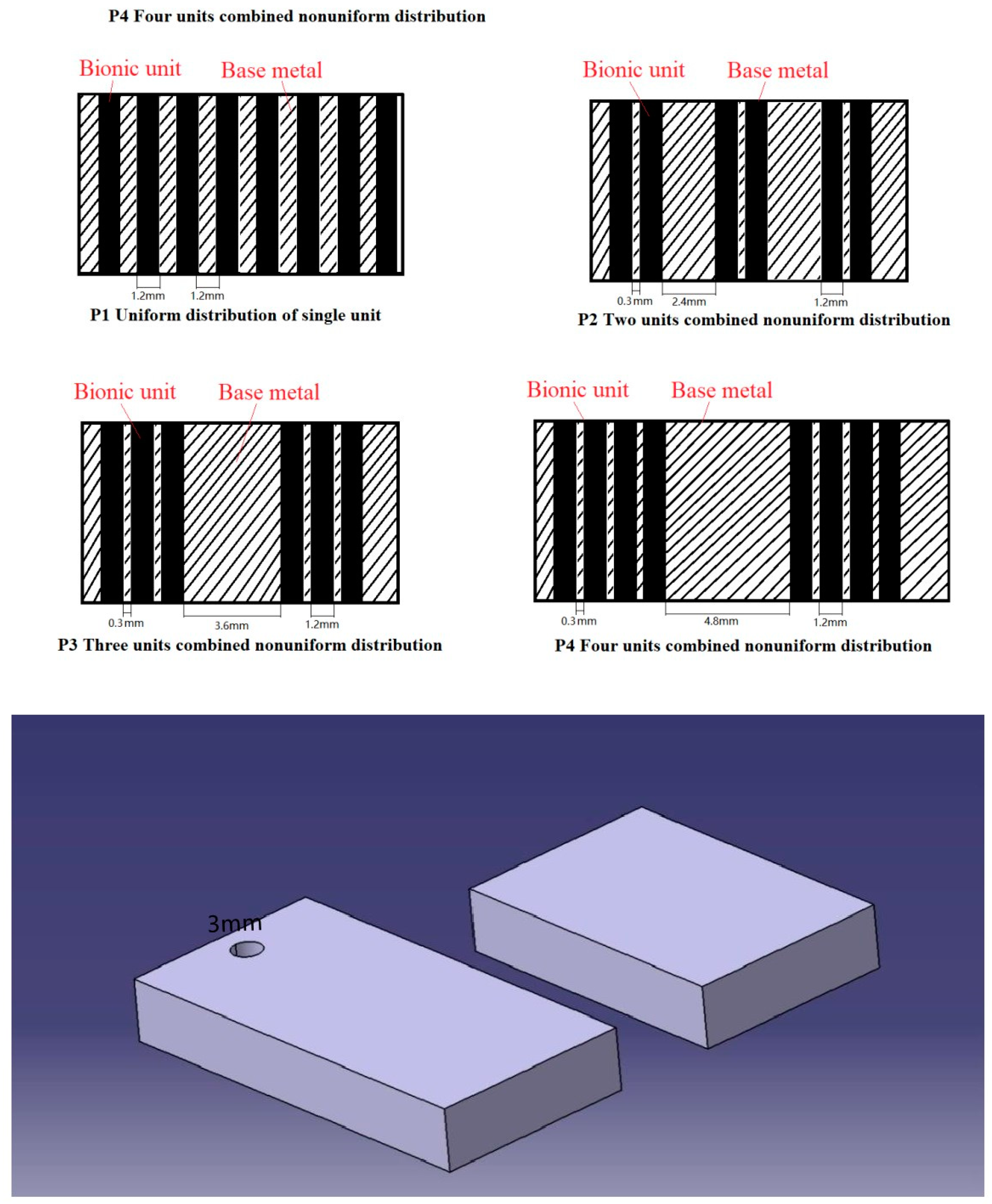
2.3. Sample Preparation

Using a DK77 electric spark cutting machine produced by Donghua CNC company in China, the fragments of the grey cast iron brake hub were processed into 100 × 20 × 10 mm3 and 40 × 20 × 10 mm3 rectangular samples, and a 3 mm round hole was drilled on the upper part of 40 rectangular samples, as shown in Figure 3. The surfaces of the samples were polished with 80#, 360#, 600#, and 1000# sandpaper to remove machining traces.
The bionic sample processing was carried out by the system of controlling the laser source’s moving track with a six degree of freedom manipulator (Figure 4). The main part of the system was the Nd: YAG pulse laser generator (XL-500WF, Rofin, Munich, Germany). A pulse beam with a wavelength of 1064 nm and a maximum output power of 300 W was emitted through the YAG crystal. The laser energy transmitted by the optical fiber was dispersed with a Gaussian distribution on the sample surface. The entire experimental laser setup was comprised of a cooling system, a two-dimensional rotating table, a six degree of freedom manipulator, and a servo control system. By adjusting the position coordinates of the manipulator in the z-axis direction, precise control of the defocusing amount of the laser spot can be realized, and the spot with the required size can meet the needs of the unit machining. The first mock exam was carried out to adjust the output laser parameters through the laser control cabinet, and ensure that the laser output energy was in accordance with the test requirements and that the size, shape, and organizational structure of the bionic cells in each model laser processing were the same. The laser parameters are shown in Table 2.

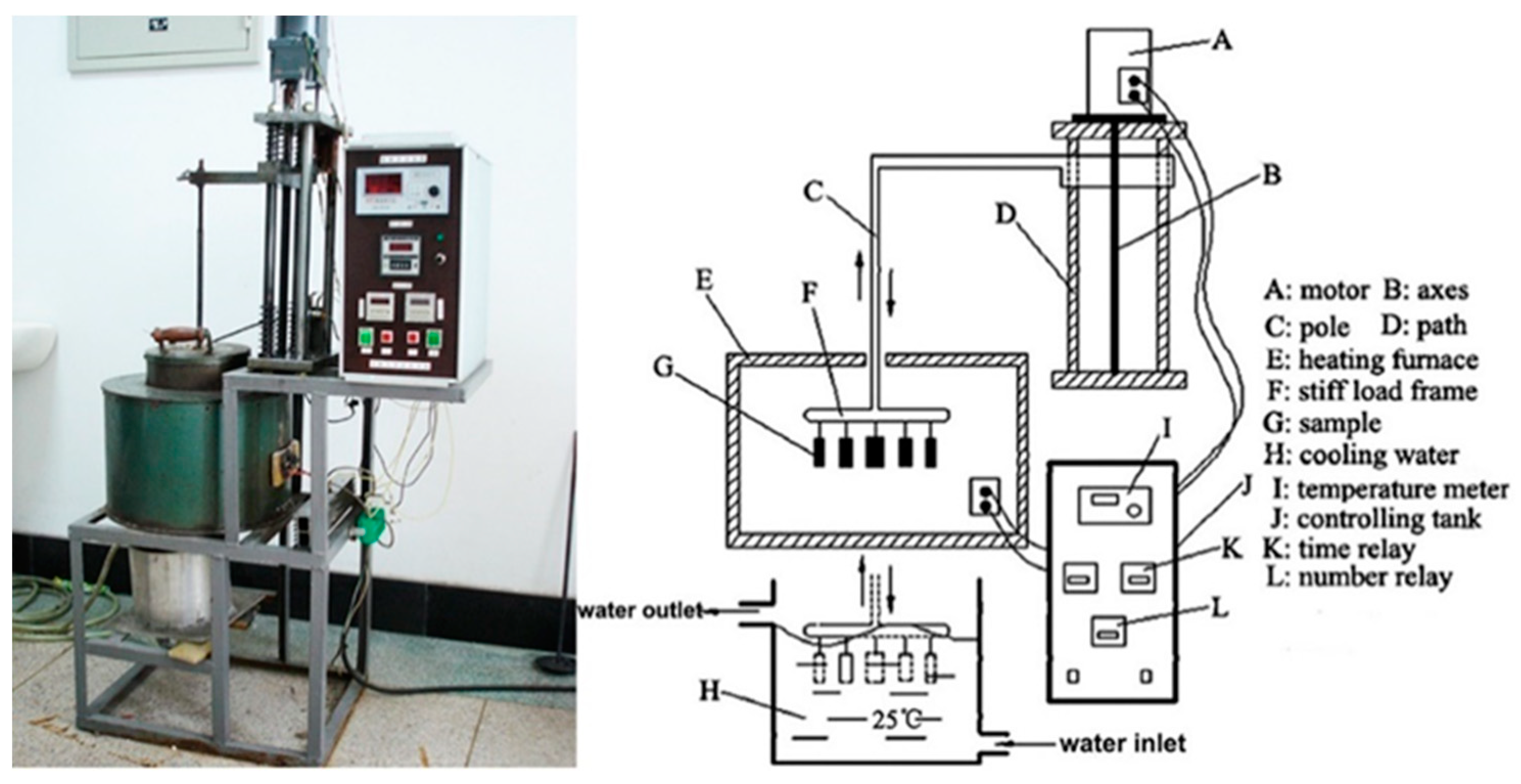
2.4. Thermal Fatigue Test
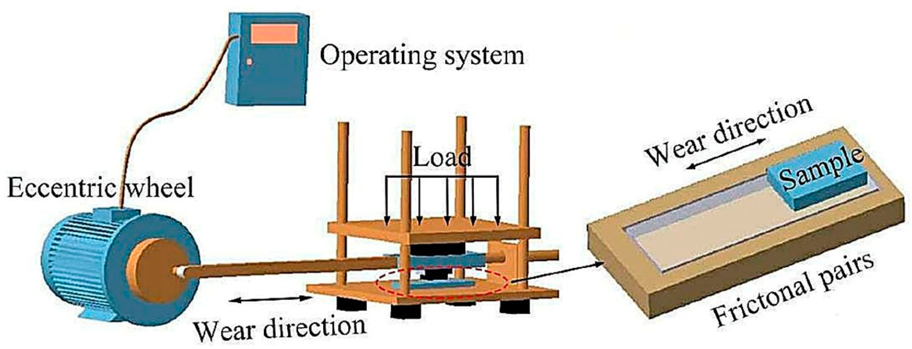
The equipment used in the thermal fatigue test was a self-made self-restrained thermal fatigue test machine, as shown in Figure 5. The heating temperature was 700 °C, and the cooling medium was running tap water. The heating time was 160 s, and the cooling time was 20 s. The melted sample and the untreated sample were placed in the thermal fatigue test machine for the thermal fatigue test. The samples were removed after the test, the number of cold and hot cycles was recorded, and finally the length and number of cracks were measured.

2.5. Wear Tests

Due to the obvious directionality of the friction between the brake drum and the brake pad, in order to better simulate the friction conditions during the actual operation of the drum brake, the matching wear test was carried out on the self-made linear reciprocating wear test machine, and the structural diagram of the test machine is shown in Figure 6. The wear testing machine is composed of a controller, a counter, a servo motor, a linkage driving mechanism, and a wear testing area. The rotation of the servo motor drives the connecting rod to create reciprocating motion. The rotation speed of the servo motor controls the relative motion speed between the friction pairs. The slideway is coated with lubricating oil to ensure smooth reciprocating motion and maintain the level. The slider is equipped with a metal bracket to adjust the load by adding different weights to the bracket. The size specifications of the friction pairs used in this test were as follows: bionic sample was 120 × 30 × 10 mm3 rectangular, the ground cast iron sample was 100 × 20 × 10 mm3 rectangular, and the edge was chamfered by 1 mm. The brake pad sample was placed under the wear test area and kept stationary, and the cast iron sample was placed in the fixture on the sliding block. The bionic friction surface processed on the sample was opposite to the brake pad. After loading, it makes contact with the brake pad and follows the guide rod for reciprocating motion. In the experiment, by adjusting the weight on the metal plate and adjusting the speed of the motor with the controller, the sliding friction process under different loads and different friction speeds was created. All the experiments were sliding dry friction experiments conducted at room temperature. The test load was 100 N, and the motor speed was 70 r/min. The stroke of the connecting rod was 0.07 m, and the wear time was set to 40 h for each rotation of the motor. After the wear experiment, the matching cast iron samples were cleaned with an ultrasonic cleaning instrument, and the wear debris on the surface of the brake pad samples was cleaned and removed. All samples were weighed by an electronic balance with an accuracy of 0.001 g. Each experiment was repeated three times, and the average weight loss of the three experiments was taken as the final experimental result.

2.6. Microstructure Observation and Wear Morphology Observation

A DK77 Electrical discharge machining was used to cut the laser-melted sample along its cross-section. Processing traces and oil stains on the cross-section were polished with different sandpaper grades. The samples were etched with a 4% nitric acid/alcohol solution to prepare them for metallographic observation. The morphology of biomimetic cells was observed under an optical microscope, and a cell without cracks and pores was selected for microstructure observation. A JEOL JSM-5600lv (SEM, Zeiss, Evo18, Oberkochen, Germany) scanning electron microscope (SEM) was used to observe the cross-section structure of the bionic unit bodies. In addition, after the unit body sample and brake pad samples were worn, their surfaces were also observed under SEM and their wear morphology was recorded. In this process, the samples did not require polishing and corrosion.
To characterize the wear performance, in addition to measuring the mass change before and after wear, the wear morphology of different biomimetic unit models and different brake pads were compared and analyzed using three-dimensional laser confocal microscopy (LEXT-OLS 3000 Olympus).

3. Results and Discussion

3.1. Structural Analysis of Non-Uniform Models of Bionic Unit of Grey Cast Iron

According to the discussion on the formation process of the unit [29,30] in the literature, the ambient temperature around the unit formation is relatively low. After remelting, a grain boundary structure with higher dislocation density is formed. This process of remelting and rapid cooling can be compared to a self-quenching process. As the entire process is continuous, the processing of the unit will increase the temperature of the surrounding material environment. For a unit that has been processed, it is equivalent to the process of heat preservation and tempering after the self-quenching process. These two processes occur one after another, which means that the unit created by laser melting and solidification has increased dislocation density and hardness and enhanced ductility and toughness. However, the distribution mode of the cell changes the interaction degree of the adjacent cell forming process. Figure 7 depicts cross-sectional morphology photos of four different biomimetic cell combinations, and Figure 8 shows thee SEM photos of the cell microstructure of different cell combinations.
It can be seen from Figure 7 that there were some differences in cell size among the four different combinations. The maximum depth of P4 was 1.089 mm, and the minimum depth of P1 was 0.878 mm. The matrix structure of the base metal was pearlite with a small amount of ferrite. During laser treatment, the heat is transferred from the surface to the interior of the base metal. The lower the ambient temperature of the base metal, the more quickly the heat input from the laser is transferred to the surrounding area, and the more heat is transferred out. The input heat can quickly diffuse to the surrounding area, and the degree of heat accumulation in the molten pool becomes weak. Subsequently, the superheated temperature of the liquid metal in the molten pool decreases, so that the laser processing area on the sample surface reaches the melting point temperature of the gray cast iron, and the melting area becomes smaller. The heat transfer in each direction of the heating area of the four distribution modes is different. The heat transfer on the surface occurs through radiation and natural convection. As more units are processed continuously, the unit melts more slowly until it eventually solidifies. The distribution mode of the unit changes the surrounding environment of the base metal, which has an impact on the shape, size, and other characteristics of the unit body. The increase in the number of unit body combinations increases the depth of the unit body embedded in the base metal, and the thickness of the unit body increases.
The change in the unit distribution had no effect on the structure of the unit, which was composed of deformed ledeburite and a small amount of residual austenite. The deformed ledeburite had the structure of martensite distributed on the cementite substrate. Normally, the pearlite is distributed on the cementite substrate, but the unit body was formed under the condition of rapid cooling. At high temperatures, the carbon dissolve in the ferrite too late to precipitate, and the supersaturated solid solution becomes martensite in ferrite. According to the X-ray (D/Max, 2500PC, Tokyo, Japan) diffraction analysis and SEM photos of the units with different distribution modes shown in Figure 9, it can be seen that the higher the ambient temperature of the base metal during the laser processing, the lower the initial austenite volume, and the higher the amount of eutectic carbide in the unit body; meanwhile, the dendrite spacing of the carbide becomes denser and finer. As shown in Figure 7, the dendrite spacing of P4 was relatively large, while that of P1 was the densest and finest.
The transverse and longitudinal microhardness distribution of the unit is shown in Figure 10b. The points are taken from the surface to the depth along the horizontal line at 25 um under the matrix and symmetrical center line of the unit, respectively. The measurement results are shown in Figure 10a,c. The microhardness of the surface of the two kinds of units was greater than that of the matrix. Due to the uniform structure on the same horizontal line, the hardness of a single unit showed little change, but there was an obvious hardness difference between the units arranged in different ways. The microhardness range of P1 was 765–820 HV, P2 was 675–725 HV, P3 was 590–640 HV, and P4 was 570–620 HV. The main reason for this hardness difference was the uneven heat transfer in the different arrangements, which resulted in different cooling rates across the entire molten pool. The top of the molten pool can radiate heat, and its cooling speed is faster. More carbide, martensite, and a small amount of austenite were formed during cooling. The temperature at the bottom of the molten pool was close to the melting point, and there was a large temperature gradient between the molten pool and the substrate. The cooling speed was slow. The austenite dendrite formed first, and then the austenite dendrite transformed into martensite. Therefore, in the depth direction, there were some differences in the microhardness of the unit, and the microhardness decreased gradually along the depth direction.

3.2. Thermal Fatigue Resistance Analysis of Non-Uniform Model of Biomimetic Unit

Under the action of cyclic thermal stress and thermal strain, the surface defects tend to produce stress concentration, thus becoming the location of crack nucleation. Due to the large amount of flake graphite in gray cast iron, each flake graphite can approximately form a micro notch in the matrix. In the process of the thermal cycle, because of thermal expansion and contraction, the internal stress is concentrated at the tip of the graphite, leading to crack initiation. As shown in Figure 11, after 20 thermal cycles, microcracks initiated at the tip of the two graphite samples and propagated along the interface, with poor bonding properties and grain boundaries. The contact area between the crack and the air was large, allowing for easy oxidation. The formation of loose oxide further promoted the crack growth. Energy Dispersive Spectrometer analysis showed that the oxide from the iron distributed into the cracks. The results showed that the stress concentration effect and oxidation corrosion promoted crack initiation and propagation.
The biomimetic unit embedded in the base metal acted as a crack-arresting unit that blocked crack growth. The local structural transformation of the base metal and the change in the temperature difference between the laser irradiation zone and the base metal generate certain types of stress that are conducive to improving surface wear resistance and fatigue resistance. At the same time, the existence of residual stress can reduce the sensitivity of the crack tip to stress as well as offset part of the driving force of the crack. The residual stress values of different models were different when they were processed; consequently, different models were used to measure residual stress. As the penetration depth of x-ray to the metal was about 20 μm, the stress value measured by the test should be the plane stress value of 20 μm deep on the surface of the unit. During the measurement, three points were selected along the laser scanning direction along the laser scanning direction in the middle of the melting unit, which were marked as A1, A2 and A3, and three points were selected as B1, B2, and B3 in the phase transition region of the unit. The D φ-sin2 φ curve of each measuring point is shown in Figure 12. Residual stress and its average values were calculated by the stress measuring instrument’s own software according to the slope of the regression line of D φ to sin2 φ. Residual tensile stress in the melting area of the biomimetic coupling unit in the laser scanning direction was approximately 202.8 MPa, and the residual compressive stress in the phase transformation area of the biomimetic coupling unit in the laser scanning direction was approximately 103.4 MPa. The molten metal in the molten pool shrank because of solidification through movement of the light beam. The melting layer and its surrounding transformation zone were combined metallurgically, which resulted in the contraction of the melting zone and the surrounding transformation zone, increasing the formation of residual tensile stress in the melting zone. Figure 13 shows the surface stress values of the unit in the four different distance distribution models. Surface stress values of the unit were lower as the number of biomimetic units in the model increased, which reflects the function of heat preservation and tempering in the processing of the unit.
When the microcrack growth is no longer dependent on the surface conditions of the material, the crack initiation phase ends, and the crack growth resistance depends on the overall properties of the material. We found that during the thermal cycle, due to the interaction between the surface layer and the thermal medium, the oxygen in the air reacts with the matrix to oxidize the surface layer. Additionally, a large amount of pearlite decomposes into ferrite and graphite, which reduces the hardness and strength of the material. As shown in Figure 14, due to the decomposition of cementite, the pearlite content was reduced, allowing the crack to expand into the matrix more easily. In the gray cast iron, the presence of graphite in the matrix was an excellent bridge for crack growth. Figure 15 shows the crack growth morphology in the macro state under the micro state. It can be seen from the figure that rapid crack growth was achieved by bridging the graphite in the matrix. Therefore, different types of graphite lead to different growth levels of macro thermal fatigue cracking.
Figure 16 shows the statistical curve of the thermal fatigue crack length and cycles of bionic units arranged in different ways from 0 to 600 times. It can be found that the fatigue resistance of the bionic model was better with the increase in the amount of bionic cell arrangement, which occurs because the bionic cell embedded in the substrate surface hinders the crack growth. With the increase in the number of thermal cycles and the continuous decarburization of the unit, the carbide and martensite phases in the unit were greatly reduced, the hardness of the unit was reduced, and the blocking effect was reduced. Therefore, in terms of the number of cracks, when the number of cycles reached 600, the number of cracks in P4 was 80, while that of P1 was 96. However, when P4 was 600 times, the maximum crack length was 2.8 mm, while that of P1 was 6.9 mm. This is due to the accumulation of energy at the crack tip because of the continuous thermal cycling, which allows the crack to break through the potential barrier of the unit. When breaking through the cell barrier, the crack deflects along the cell edge, which means that the crack propagation is interrupted. Therefore, with the increase in the number of elements in the arrangement mode, the maximum length of the crack was effectively shortened in the thermal cycle test of the sample, and the surface crack mode changed from a large, long crack to a fine, small crack (although the difference in the number of cracks was not particularly significant).

3.3. Thermal Fatigue Resistance Analysis of Non-Uniform Models of Biomimetic Units

Figure 14 depicts the bionic unit structure after 600 fatigue tests. From Figure 14b, many dispersed point graphite points can be seen. This shows that in the process of thermal fatigue, the cyclic thermal process causes the martensite phase to decompose and the carbon element to precipitate. In the biomimetic unit, tiny point like and strip like cementite could also be seen, and were distributed in the basic phase composed of ferrite. Figure 17 shows the weight loss results of the bionic samples with different distribution combinations and the semi-metallic brake pads after 150, 300, 450, and 600 thermal cycles. It can be seen from the results that with the increase in fatigue time, the wear amount of the bionic samples also increased. Compared with the blank sample, the wear loss of the bionic sample was much less important. Thus, in the early stages of fatigue, the bionic unit in the bionic sample effectively resists wear. With the increase in the fatigue time, the structure of the unit and the matrix change to varying degrees. The number of non-equilibrium phases with higher hardness in the unit decreases, which makes the hardness of the unit decrease.
There are different numbers of microcracks on the surface of the fatigue specimen. During the wear process, the edge of these microcracks is easier to peel off, which increases the wear amount of the specimen. Therefore, the number of microcracks in the sample surface has a great influence on the wear resistance of the sample. According to the results of wear loss, the samples with different unit distributions have different wear surfaces. P1 had the largest wear loss weight, and it also had the largest wear loss compared to the worn brake pads. This is because during the process of wear, with the increase in fatigue times, the unit is gradually impacted by the parent crack, which causes it to crack, and a large number of microcracks are produced on the surface. Moreover, with the increase in wear on the surrounding parent metal, the unit embedded in the parent metal will gradually be exposed to the friction surface. In this case, the microcracks on the surface of the unit will cause the unit to wear off and increase the amount of wear. The wear of P4 was most similar to that of P1. This is because the principle of the same unit area was adopted in the design of the bionic surface, so the surface of the base metal with a relatively large area on the P4 surface was exposed. In the process of wear, the area loses the protection of the unit body, so it also experiences relatively significant wear loss. P3 had the lowest amount of wear of all of the samples due to many factors. When the unit had the P3 distribution combination, the heat preservation and tempering process of the unit produced during the processing process increased the toughness of the unit. At the same time, the combined distribution of the units can protect each other during the wear process, which effectively blocks the development of cracks, reduces the micro cracks on the surface of the unit, and prevents excessive wear of the brake pads on the unit.
Figure 18 shows the surface wear morphology of different unit combinations after 600 thermal fatigue cycles. With the increase in fatigue times, different degrees of wear appeared on the surface of the unit, caused by the micro cracks peeling off the surface of the unit. With the increase in the number of units in each combination of units, the degree of wear was lighter, because the combined units protect each other, resulting in the relatively uniform wear that occurred between the units. Due to the wear and loss of support and protection of the matrix structure around P1, the brake pads caused more damage to P1 during the wear process, and the surface peeling was more serious.

4. Conclusions

In order to improve the wear resistance and thermal fatigue resistance of gray cast iron surface. As a result of previous studies, this paper makes some innovations and improvements. In order to improve the performance of the whole surface, the original average distribution hardening model was designed as a non-uniform distribution hardening model. The results showed that the structure, hardness, and grain size of the melting zone can be strengthened by the model of non-uniform strengthening, and the wear resistance and fatigue resistance of the whole gray cast iron surface can be improved. The specific innovative conclusions of this paper are as follows:
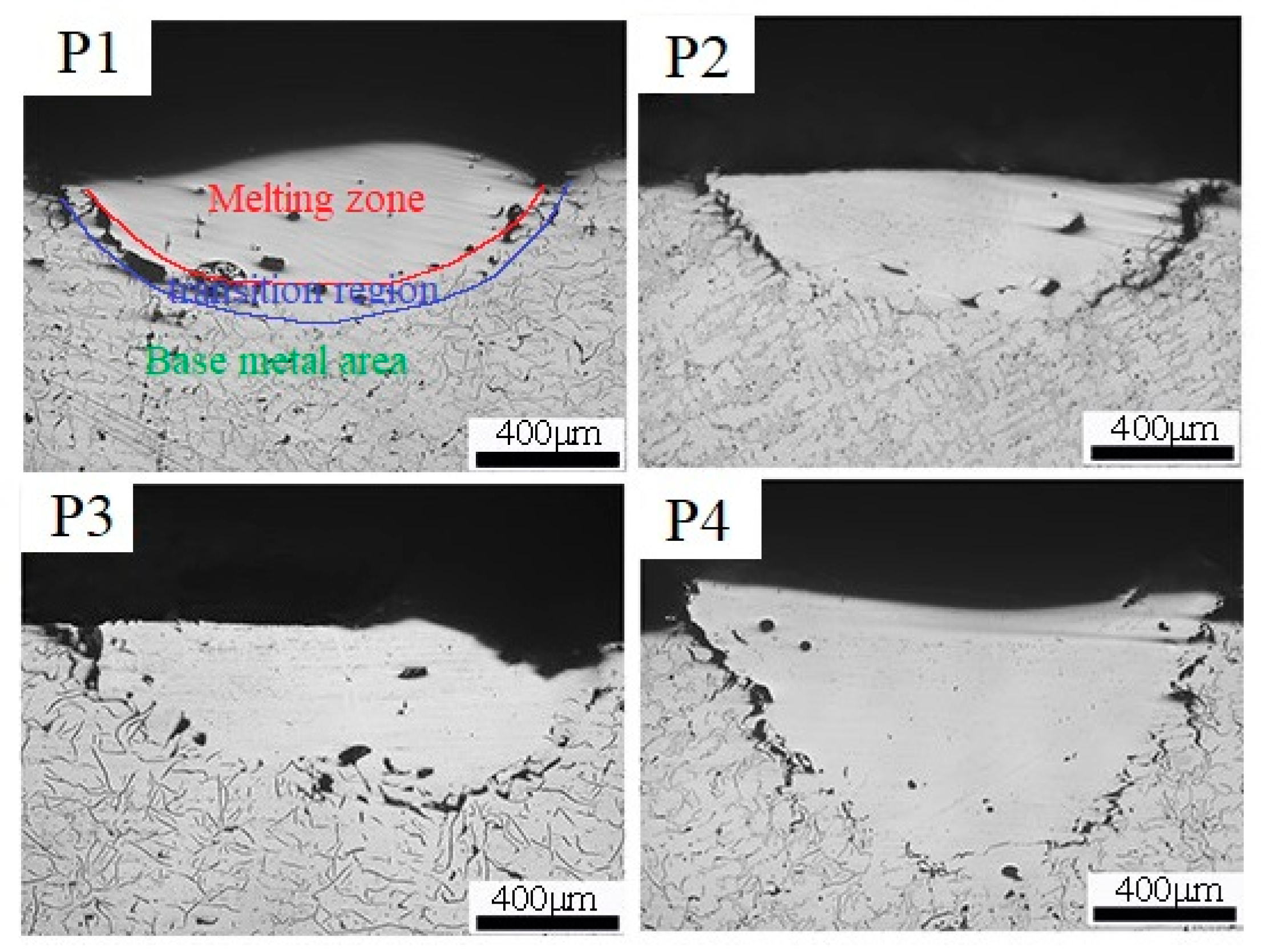
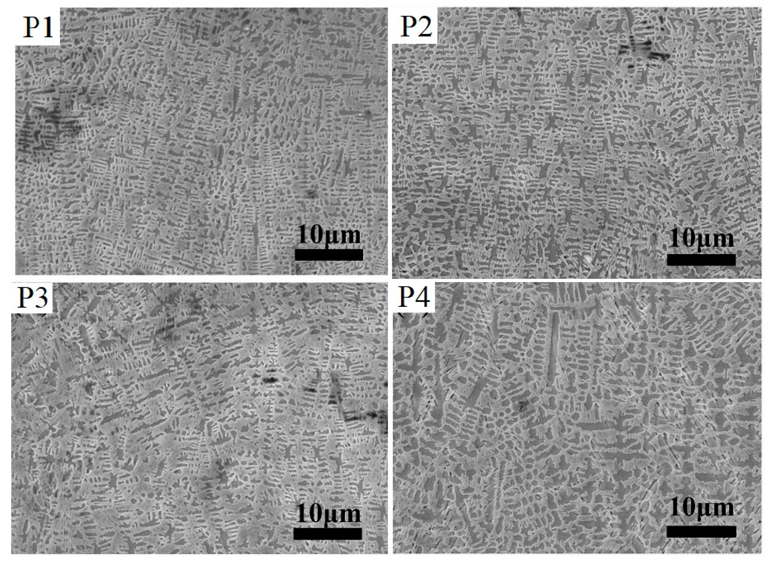
  • In the process of continuous laser remelting strengthening on the surface of gray cast iron, the adjacent melting zones will affect each other, resulting in heat preservation and a tempering effect, so that the area of the melting zone increases, but the grain size also increases accordingly. The hardness decreased from 765–820 HV (Hardness of Vickers) to 570–620 HV.
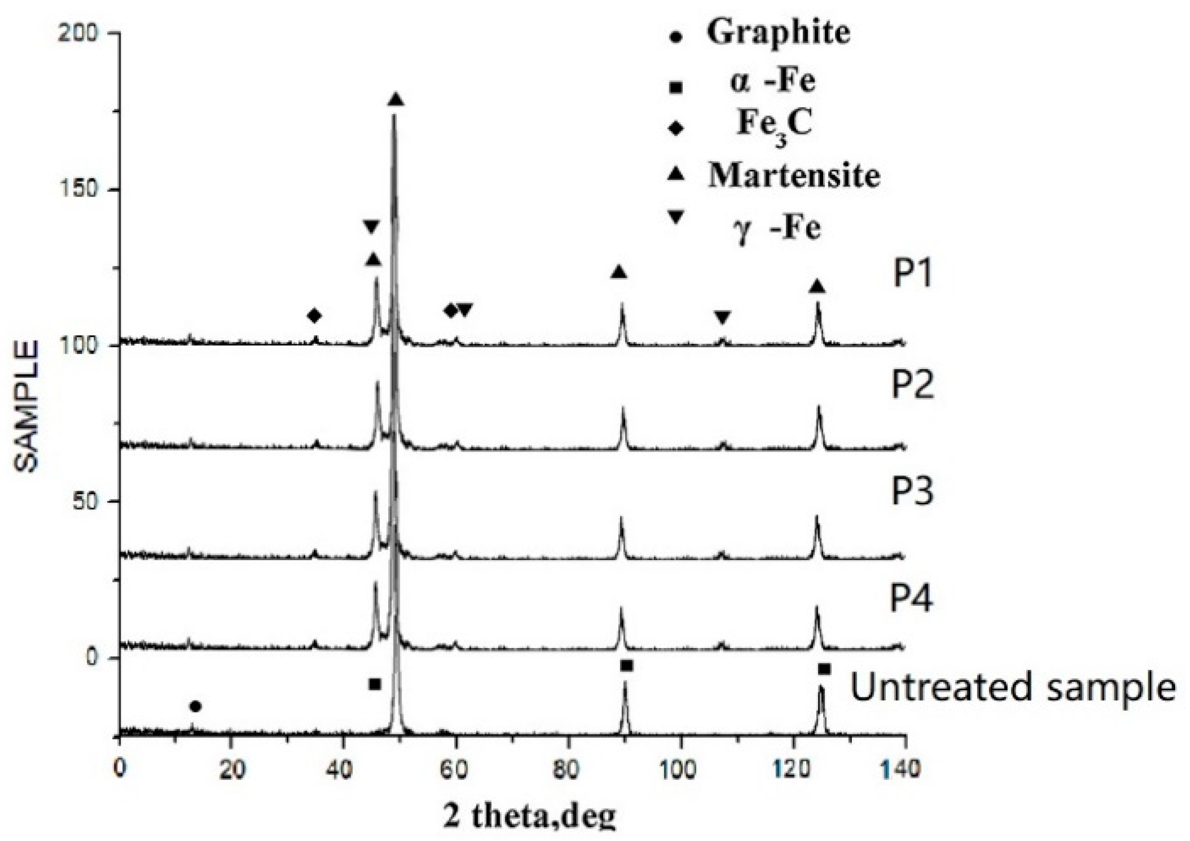
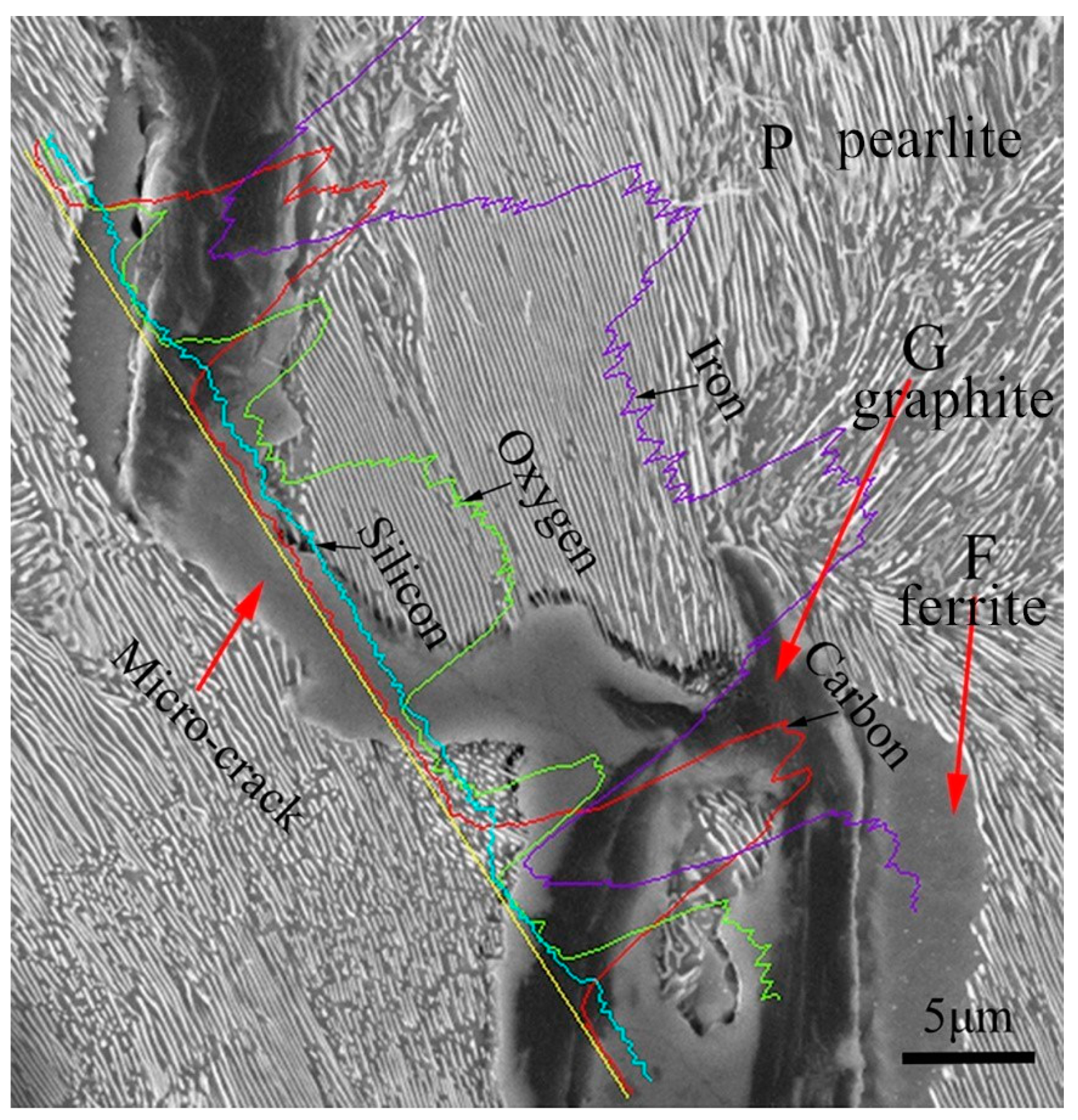
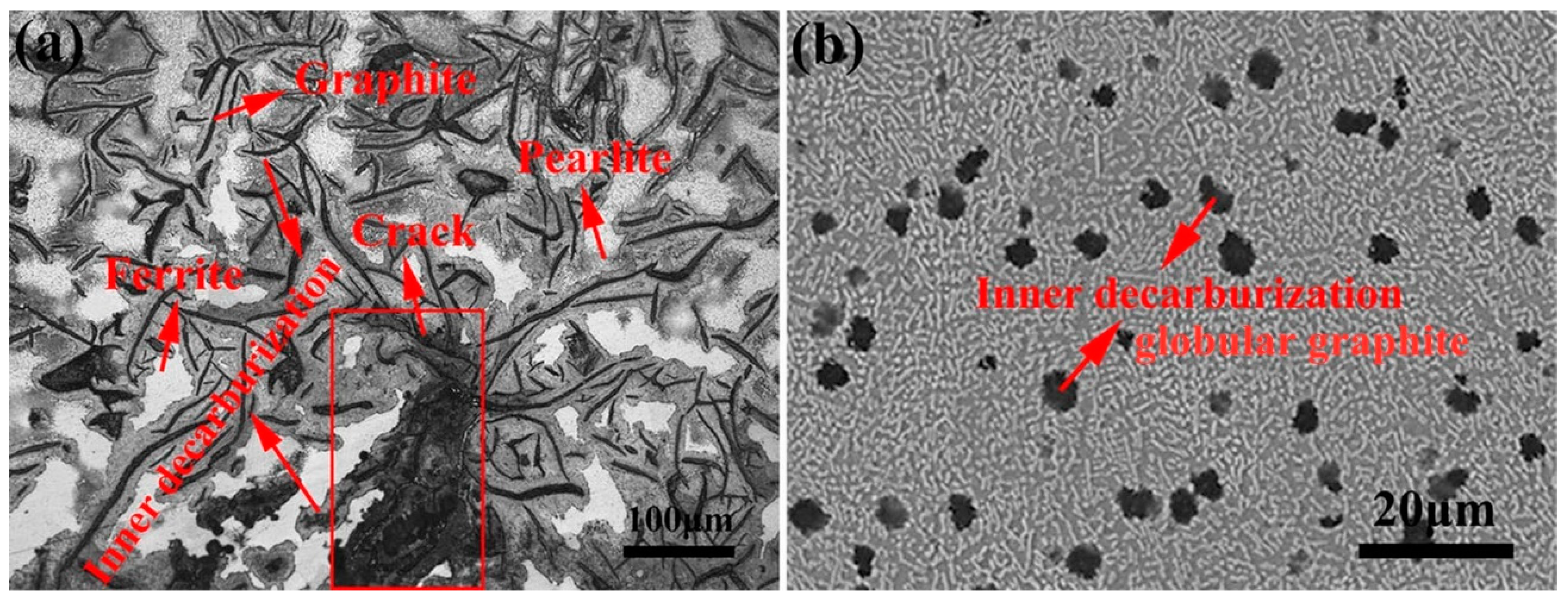
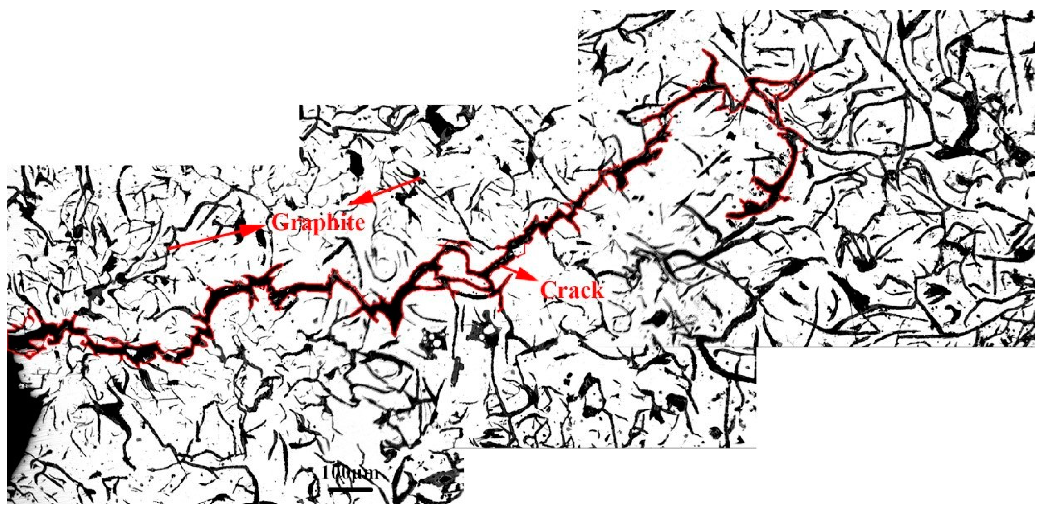
  • The mechanism of crack initiation in the early stage of thermal fatigue of gray iron was analyzed by EDS, and the phase transformation law of the microstructure in the melting zone was determined at the later stage of thermal fatigue.
  • The maximum residual tensile stress was 204 mpa in the melting zone and 103.4 mpa in the phase transformation zone
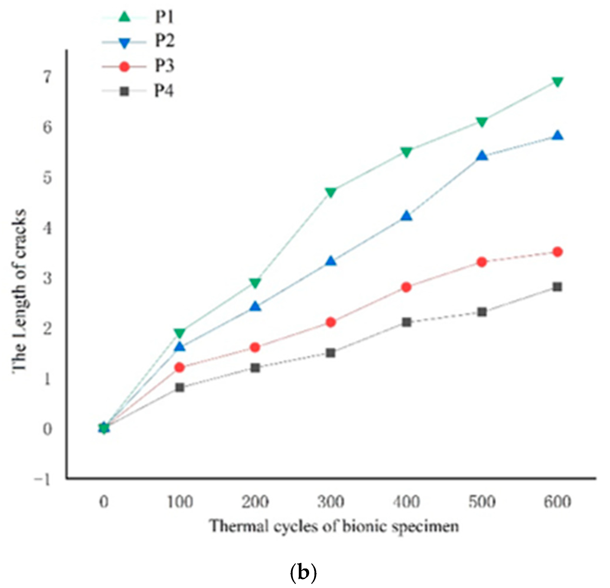
  • The thermal fatigue test showed that the greater the number of distribution strips in the melting zone, the longer the crack initiation time near the remelting zone, and the slower the propagation speed.
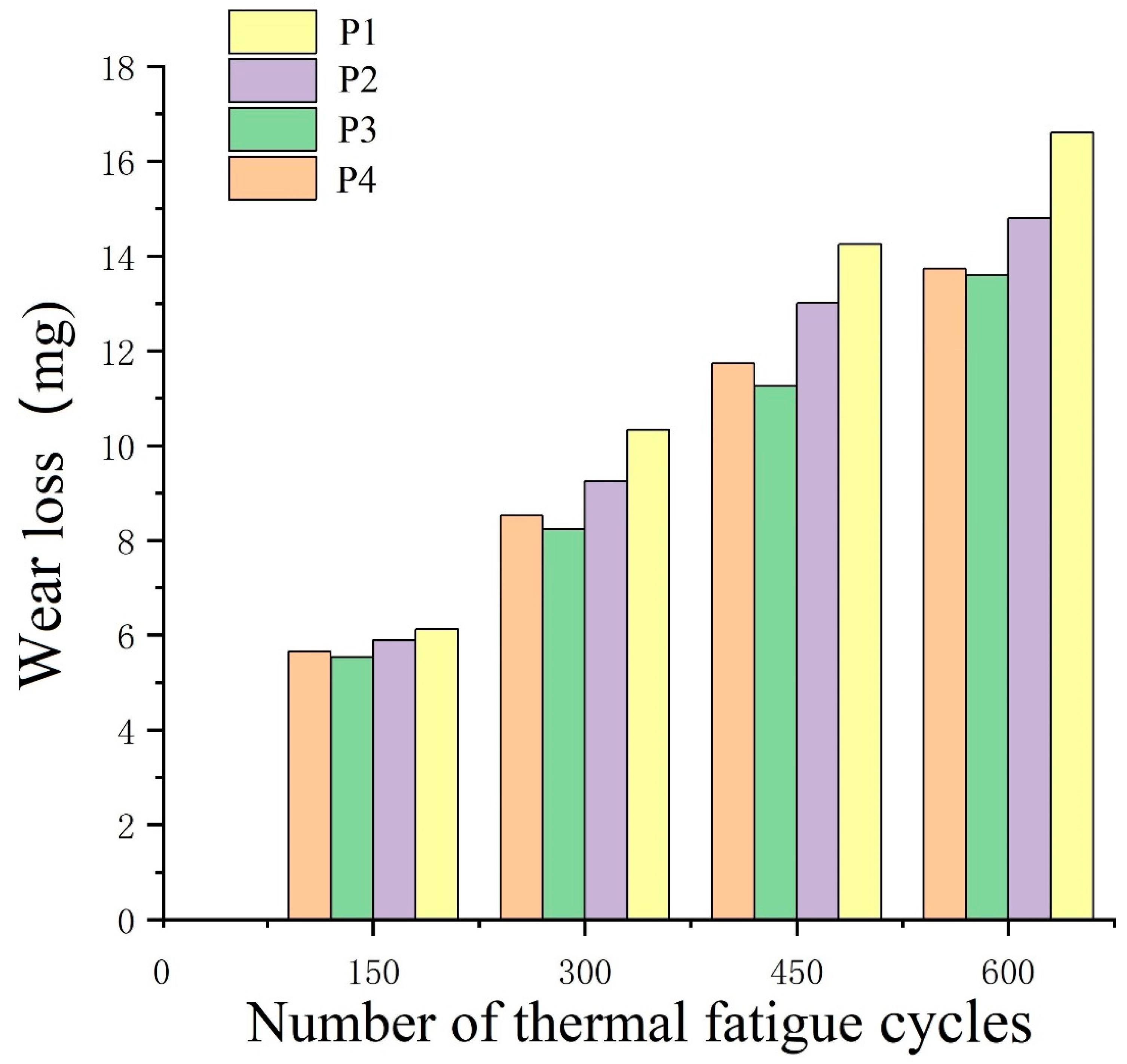
  • According to the wear test results of different blocks, it can be determined that the P3 model was the best, and the wear resistance of P1 was increased by 21.3%. The wear resistance test results were P3 > P2 > P4 > P1.

Author Contributions

Conceptualization, H.Y. and T.Z.; data curation, H.Z. and Q.W.; funding acquisition, H.Z.; methodology, H.Y.; project administration, H.Z.; validation, H.Y.; writing—original draft, T.Z.; writing—review and editing, H.Y. All authors have read and agreed to the published version of the manuscript.

Funding

This work was supported by Project 985-High Performance Materials of Jilin University, Project 985-Bionic Engineering Science and Technology Innovation, National Natural Science Foundation of China (U1601203), and double first-class project by Jilin Province and Jilin University (SXGJXX2017-14).

Acknowledgments

Acknowledgments are made to the Key Laboratory of Automobile Materials of Jilin University for the use of scanning electron microscopy and X-ray diffraction.

Conflicts of Interest

The authors declare no conflict of interest regarding the publication of this paper. I would like to declare on behalf of my co-authors that the work described was original research that has not been published previously, and not under consideration for publication elsewhere, in whole or in part. All the authors listed have approved the manuscript that is enclosed.

References

  1. Hussain, A.; Ahmad, I.; Hamdani, A.H.; Nussair, A.; Shahdin, S. Laser surface alloying of Ni-plated steel with CO2 laser. Appl. Surf. Sci. 2007, 253, 4947–4950. [Google Scholar] [CrossRef]
  2. Siyang, W.; Hong, Z. Effect of different hardness units on fatigue wear resistance of low hardenability steel. Opt. Laser Technol. 2020, 130, 180–184. [Google Scholar]
  3. Ren, L.Q.; Han, Z.W.; Li, J.J.; Tong, J. Effects of non-smooth characteristics on bionic bulldozer blades in resistance reduction against soil. J. Terrramech. 2003, 39, 22–30. [Google Scholar] [CrossRef]
  4. Tong, J.; Almobarak, M.A.M.; Ma, Y.H.; Ye, W.; Zheng, S. Biomimetic anti-abrasion surface of a cone form component against soil. J. Bionic Eng. 2010, 7, S36–S42. [Google Scholar] [CrossRef]
  5. Qingchun, G.; Hong, Z. Effect of medium on friction and wear properties of compacted graphite cast iron processed by biomimetic coupling laser remelting process. Appl. Surf. Sci. 2009, 255, 6266–6273. [Google Scholar]
  6. Zang, C.; Zhou, T.; Zhou, H.; Yuan, Y.; Zhang, P.; Meng, C.; Zhang, Z. Effects of substrate microstructure on biomimetic unit properties and wear resistance of H13 steel processed by laser remelting. Opt. Laser Technol. 2018, 106, 299–310. [Google Scholar] [CrossRef]
  7. Meng, C.; Zhou, H.; Zhang, H.; Tong, X.; Cong, D.; Wang, C.; Ren, L. The comparative study of thermal fatigue behavior of H13 die steel with biomimetic non-smooth surface processed by laser surface melting and laser cladding. Mater. Des. 2013, 51, 886–893. [Google Scholar] [CrossRef]
  8. Cong, D.; Zhou, H.; Yang, M.; Zhang, Z.; Zhang, P.; Meng, C.; Wang, C. The mechanical properties of H13 die steel repaired by a biomimetic laser technique. Opt. Laser Technol. 2013, 53, 1–8. [Google Scholar] [CrossRef]
  9. Zhou, H.; Zhang, P.; Sun, N.; Wang, C.T.; Lin, P.Y.; Ren, L.Q. Wear properties of compact graphite cast iron with bionic units processed by deep laser cladding WC. Appl. Surf. Sci. 2010, 256, 6413–6419. [Google Scholar] [CrossRef]
  10. Tong, X.; Zhou, H.; Chen, L.; Zhang, Z.-H.; Ren, L.-Q. Effects of c content on the thermal fatigue resistance of cast iron with biomimetic non-smooth surface. Int. J. Fatigue 2008, 30, 1125–1133. [Google Scholar]
  11. Almeida, A.; Carvalho, F.; Carvalho, P.A.; Vilar, R. Laser developed Al-Mo surface alloys: Microstructure, mechanical and wear behaviour. Surf. Coat. Technol. 2006, 200, 4782–4790. [Google Scholar] [CrossRef]
  12. Ren, L.Q.; Liang, Y.H. Biological couplings: Classification and characteristic rules. Sci. China Ser. E Technol. Sci. 2009, 52, 2791–2800. [Google Scholar] [CrossRef]
  13. Kamat, S.; Su, X.; Ballarini, R.; Heuer, A.H. Structural Basis for the Fracture Toughness of the Shell of the Conch Strombus Gigas. Nature 2000, 405, 1036–1040. [Google Scholar] [CrossRef] [PubMed]
  14. Ren, L.Q.; Liang, Y.H. Functional characteristics of dragonfly wings and progress in bionic research. Sci. China Sci. Technol. 2013, 56, 11–25. [Google Scholar] [CrossRef]
  15. Yang, H.; Wang, Q.; Zhou, T.; Zhou, H. The Relationship between the Model of the Laser Biomimetic Strengthening of Gray Cast Iron and Matching between Different Brake Pads. Metals 2020, 10, 184. [Google Scholar] [CrossRef] [Green Version]
  16. Chen, Z.; Zhu, Q.; Wang, J.; Yun, X.; He, B.; Luo, J. Behaviors of 40Cr steel treated by laser quenching on impact abrasive wear. Opt. Laser Technol. 2018, 103, 118–125. [Google Scholar] [CrossRef]
  17. Lu, H.; Liu, M.; Yu, D.; Zhou, T.; Zhou, H.; Zhang, P.; Bo, H.; Su, W.; Zhang, Z.; Bao, H. Effects of Different Graphite Types on the Thermal Fatigue Behavior of Bionic Laser-Processed Gray Cast Iron. Metall. Mater. Trans. A 2018, 49, 5848–5857. [Google Scholar] [CrossRef]
  18. Zhou, H.; Tong, X.; Zhang, Z.; Li, X.; Ren, L. The thermal fatigue resistance of cast iron with biomimetic non-smooth surface processed by laser with different parameters. Mater. Sci. Eng. A 2006, 428, 141–147. [Google Scholar] [CrossRef]
  19. Gan, L.; Liang, G.Y. Sliding abrasion resistance of gray cast iron surfaces with bio-inspired groove lines and groove stripes. Mater. Res. Express 2018, 5, 096525. [Google Scholar] [CrossRef]
  20. Yu, D.; Zhou, T.; Zhou, H. Non-single bionic coupling model for thermal fatigue and wear resistance of gray cast iron drum brake. Opt. Laser Technol. 2019, 111, 781–788. [Google Scholar] [CrossRef]
  21. Chang, G.; Zhou, T.; Zhou, H.; Zhang, P.; Ma, S.; Zhi, B.; Wang, S. Effect of Composition on the Mechanical Properties and Wear Resistance of Low and Medium Carbon Steels with a Biomimetic Non-Smooth Surface Processed by Laser Remelting. Metals 2020, 10, 37. [Google Scholar] [CrossRef] [Green Version]
  22. Chen, Z.K.; Zhou, T.; Zhang, H.F.; Yang, W.S.; Zhou, H. Influence of Orientations of Bionic Unit Fabricated by Laser Remelting on Fatigue Wear Resistance of Gray Cast Iron. J. Mater. Eng. Perform. 2015, 24, 2511–2520. [Google Scholar] [CrossRef]
  23. Su, W.; Zhou, T.; Sui, Q.; Zhang, P.; Zhou, H.; Li, H.; Zhang, Z.H. Study on the relationship between intervals among laser stripes and the abrasion resistance of biomimetic laser textured surfaces. Opt. Laser Technol. 2018, 107, 380–388. [Google Scholar] [CrossRef]
  24. Su, W.; Zhou, T.; Zhang, P.; Zhou, H.; Li, H. Effect of distribution of striated laser hardening tracks on dry sliding wear resistance of biomimetic surface. Opt. Laser Technol. 2018, 98, 281–290. [Google Scholar] [CrossRef]
  25. Zhang, H.; Zhang, P.; Sui, Q.; Zhao, K.; Zhou, H.; Ren, L. Influence of Multiple Bionic Unit Coupling on Sliding Wear of Laser-Processed Gray Cast Iron. J. Mater. Eng. Perform. 2017, 26, 1614–1625. [Google Scholar] [CrossRef]
  26. Chen, Z.K.; Zhou, T.; Zhao, R.Y.; Zhang, H.F.; Lu, S.C.; Yang, W.S.; Zhou, H. Improved fatigue wear resistance of gray cast iron by localized laser carburizing. Mater. Sci. Eng. A 2015, 644, 1–9. [Google Scholar] [CrossRef]
  27. Su, Q.; Bai, S.; Han, J.; Ma, Y.; Yu, Y.; Deng, Y.; Wu, M.; Zheng, C.; Hu, A. Precise laser trimming of alloy strip resistor: A comparative study with femtosecond laser and nanosecond laser. J. Laser Appl. 2020, 32, 022013. [Google Scholar] [CrossRef]
  28. Sui, Q.; Zhang, P.; Zhou, H.; Liu, Y.; Ren, L. Influence of Cycle Temperature on the Wear Resistance of Vermicular Iron Derivatized with Bionic Surfaces. Metall. Mater. Trans. A 2016, 47, 5534–5547. [Google Scholar] [CrossRef]
  29. Wang, C.-T.; Zhou, H.; Zhang, Z.; Zhao, Y.; Cong, D.-L.; Meng, C.; Zhang, P.; Ren, L.-Q. Mechanical property of a low carbon steel with biomimetic units in different shapes. Opt. Laser Technol. 2013, 47, 114–120. [Google Scholar] [CrossRef]
  30. Jing, Z.; Zhou, H.; Zhang, P.; Wang, C.; Meng, C.; Cong, D. Effect of thermal fatigue on the wear resistance of graphite cast iron with bionic units processed by laser cladding WC. Appl. Surf. Sci. 2013, 271, 329–336. [Google Scholar] [CrossRef]
  31. Xu, L.W. Application and analysis of surface engineering technology in mold manufacturing. Telecommun. Power Technol. 2017, 34, 114–115. [Google Scholar]
  32. Ma, S.; Zhou, T.; Zhou, H.; Chang, G.; Zhi, B.; Wang, S. Bionic Repair of Thermal Fatigue Cracks in Ductile Iron by Laser Melting with Different Laser Parameters. Metals 2020, 10, 101. [Google Scholar] [CrossRef] [Green Version]
  33. Zhi, B.; Zhou, T.; Zhou, H.; Zhang, P.; Ma, S.; Chang, G. Improved localized fatigue wear resistance of large forging tools using a combination of multiple coupled bionic models. SN Appl. Sci. 2019, 122, 63–68. [Google Scholar] [CrossRef] [Green Version]
Figure 1. Microstructure of cast iron material. (a) Graphite structure with cast iron. (b) Matrix structure of matched cast iron. (c) Pearlite structure amplification with cast iron.
Metals 10 01257 g001
Figure 2. Semi-metallic brake pads.
Metals 10 01257 g002
Figure 3. Bionic specimens with different distance distributions.
Metals 10 01257 g003
Figure 4. Schematic diagram of laser processing process.
Metals 10 01257 g004
Figure 5. Shape and test process of the thermal fatigue testing machine.
Metals 10 01257 g005
Figure 6. Linear reciprocating sliding friction and wear tester.
Metals 10 01257 g006
Figure 7. Photographs of cross section shapes of four different biomimetic unit combinations. The section of the bionic unit body is composed of the melting zone, transition zone, and base metal.
Metals 10 01257 g007
Figure 8. Electron micrograph of microstructure in melting and transition zone of biomimetic unit.
Metals 10 01257 g008
Figure 9. X-ray diffraction analysis of elements with different distribution.
Metals 10 01257 g009
Figure 10. Distribution of microhardness in transverse and longitudinal direction of unit. (a) Hardness of unit in transverse direction (b)Hardness distribution of unit (c) Depth hardness distribution of unit.
Metals 10 01257 g010
Figure 11. Crack initiation source of gray cast iron and EDS analysis of the elemental composition.
Metals 10 01257 g011
Figure 12. The D φ—sin2 φ curve of each measuring point.
Metals 10 01257 g012
Figure 13. Surface stress values of elements in four models of different distance distribution.
Metals 10 01257 g013
Figure 14. Microstructure of the cross sections of specimen after thermal 600 cycles. (a) the substrate; (b) the bionic unit
Metals 10 01257 g014
Figure 15. Micromorphology of macro thermal fatigue crack propagation.
Metals 10 01257 g015
Figure 16. Statistical curves of the length and number of thermal fatigue cracks of biomimetic units arranged in different ways from 0 to 600 times. (a) The quantity of cracks, (b)The length of cracks
Metals 10 01257 g016aMetals 10 01257 g016b
Figure 17. Weight loss results of thee bionic samples in the wear test with semi-metallic brake pads after thermal cycling.
Metals 10 01257 g017
Figure 18. Surface wear morphology of different unit combinations after 600 thermal fatigue cycles.
Metals 10 01257 g018
Table 1. Chemical compositions of nodular cast iron.
ElementCSiMnPSCuCrFe
Content3.411.610.960.020.010.3150.180Bal.
Table 2. Laser parameters.
SampleElectric Current
(A)
Pulse Duration
(ms)
Frequency
(Hz)
Defocus Amount
(mm)
Laser Energy Density
(J/mm2)
No.1120715155144.7

