Article

Characterization of Microstructure in High-Hardness Surface Layer of Low-Carbon Steel

1
State Key Laboratory of Advanced Special Steel, Shanghai Key Laboratory of Advanced Ferrometallurgy, School of Materials Science and Engineering, Shanghai University, Shanghai 200444, China
2
National High Magnetic Field Laboratory, Florida State University, Tallahassee, FL 32310, USA
*
Authors to whom correspondence should be addressed.
Metals 2020, 10(8), 995; https://doi.org/10.3390/met10080995
Submission received: 24 June 2020 / Revised: 16 July 2020 / Accepted: 19 July 2020 / Published: 23 July 2020

Abstract

:
Surface hardening improves the strength of low-carbon steel without interfering with the toughness of its core. In this study, we focused on the microstructure in the surface layer (0–200 μm) of our low-carbon steel, where we discovered an unexpectedly high level of hardness. We confirmed the presence of not only upper bainite and acicular ferrite but also lath martensite in the hard surface layer. In area of 0–50 μm, a mixed microstructure of lath martensite and B1 upper bainite was formed as a result of high cooling rate (about 50–100 K/s). In area of 50–200 μm, a mixed microstructure of acicular ferrite and B2 upper bainite was formed. The average nanohardness of the martensite was as high as 9.87 ± 0.51 GPa, which was equivalent to the level reported for steel with twenty times the carbon content. The ultrafine laths with an average width of 128 nm was considered to be a key cause of high nanohardness. The average nanohardness of the ferrites was much lower than for martensite: 4.18 ± 0.39 GPa for upper bainite and 2.93 ± 0.30 GPa for acicular ferrite. Yield strength, likewise, was much higher for martensite (2378 ± 123 MPa) than for upper bainite (1007 ± 94 MPa) or acicular ferrite (706 ± 72 MPa). The high yield strength value of martensite gave the surface layer an exceptional resistance to abrasion to a degree that would be unachievable without additional heat treatment in other steels with similar carbon content.

1. Introduction

Low-carbon steels are widely valued for their high ductility and toughness, but their strength and hardness have remained inferior to other steels [1,2,3]. In fact, for most applications of low-carbon steels, both hardness and strength, especially surface hardness, are important basic mechanical properties. The hardened surface layer improves the strength of the material while the tough core is retained.
Many surface hardening methods have been developed, such as laser hardening, induction hardening, carburizing, and nitriding [4]. However, all these methods require extra processing, which increases the cost. In a previous study, we produced an as-cast low-carbon steel with a hardened surface layer without introducing extra processing steps such as alloying, rolling, heat treatment, or surface treatment [5]. The average Vickers hardness in the surface area was 420 HV, which reached the hardness of martensite. At the same time, our steel has similar ductility and toughness as that of ordinary low-carbon steel.
On a microscale, the properties of different microstructures vary greatly, especially in quenched low-carbon steel, which can contain various microstructures—bainite, acicular ferrite, polygonal ferrite, and lath martensite, sometimes coexisting within a small area [6,7]. Lath martensite, usually the hardest microstructure in low-carbon steel, is characterized by ultrafine laths, appearing roughly parallel in packets separated from one another by high-angle boundaries [8,9]. During martensite transformation, interstitially dissolved carbon atoms line up in one direction, creating a body-centered tetragonal (bct) rather than a body-centered cubic (bcc) crystal structure [10,11,12,13,14,15,16,17]. Bainite, the second hardest microstructure, is characterized by parallel fine grains, either laths or plates, in separate blocks [11,18]. Acicular ferrite is characterized by randomly distributed needles with high-angle misorientation [19,20].
In current study, we aim to elucidate the main microstructures in the hard surface layer. Furthermore, in order to tease apart the properties of various microstructures, we characterized them by using nanoscale hardness tests. We believe that by adjusting the fabrication parameters as we did, researchers should be able to get the same structure with the same properties that we were able to achieve. We quantitatively characterized each constituent in the hard surface layer, including phase, morphology, and hardness/strength. We analyzed the main cause of high hardness in the surface layer and deduced the probable formation process of the mixed microstructure.

2. Materials and Methods

Rods of TG30 steel were heated to 1600 °C in an induction furnace. FeO was added to adjust free oxygen content to 35–50 ppm. Fe-Ti was added to the melt to adjust Ti (0.01–0.02%). Fe-Mn and Fe-Si were sequentially added to adjust Mn content and Si content (see Table 1 for chemical compositions). Two 9-mm-thick copper plates with a 2.5-mm-wide chamber between them were pressed into the melt and removed. This step took 0.24 s, during which heat transferred from the center to the surface and then to the copper plates, resulting in a flat steel sheet, 2.5 × 75 × 100 mm3, which was then subjected to 30 s of air cooling and finally quenched in water. The solidification rates, as simulated using Procast software (Version 2018, ESI Group, Paris, France), were about 900–1000 K/s at 0–50 μm depth and about 400–900 K/s at 50–200 μm depth. The rates were in the sub-rapid solidification range.
A 10 mm × 5 mm × 2.5 mm sample was cut from the sheet. The cross-sectional plane of the sample was milled and then polished using 0.05 μm Al2O3 suspension. The prior austenitic grains were etched using a picric acid solution and measured using the linear intercept method. The average prior austenitic grain size was 152 μm near the surface. The sample was then repolished and re-etched using 4% nital solution. We used a Hitachi SU1510/JSM-6700F SEM (Hitachi Group, Tokyo, Japan) to obtain room-temperature microstructure images. From each of the three main microstructure types found at the surface, we extracted a small specimen (4 μm × 2 μm × 50 nm) using a Helios nanolab 600 Focused Ion Beam (FIB, FEI company, Hillsboro, OR, USA). With a JEM-ARM200cF TEM (JEOL Ltd., Tokyo, Japan), we identified the Selected Area Electron Diffraction (SAED) patterns of each microstructure in each specimen [21].
For nanoindentation, we marked the area of each type of microstructure in the cross-sectional plane of the original sample using a Vickers hardness indenter (Shanghai Everone Precision Instruments Co., Ltd., Shanghai, China). We then repolished it with a Vibromet 2 vibratory polisher (Buehler Ltd., Lake Bluff, IL, USA) in the preparation for nanoindentation tests. We applied the continuous stiffness method (CSM) using an Agilent U9820A Nano Indenter G200 (Agilent Technologies, Inc., Santa Clara, CA, USA) equipped with a TB-13989 Berkovich-type diamond head (Agilent Technologies, Inc., Santa Clara, CA, USA) with a displacement resolution less than 0.02 nm. The Poisson’s ratio v was set at 0.3. To ensure the reliability of test results, the thermal drift effect during pressing was automatically deducted. Eight test points were indented on each microstructure, and the indentations were arranged in a dot array (Figure 1a). To avoid overlapping, the centers of test points were placed 20 μm apart. For each indentation, we immediately took readings for nanohardness directly from the software of nanoindentation equipment. We plotted a nanohardness–displacement curve for each indentation. After nanoindentation tests, the cross-sectional plane of the sample was etched again to screen the nanoindentations on target microstructures (Figure 1b).

3. Results

3.1. Microstructure

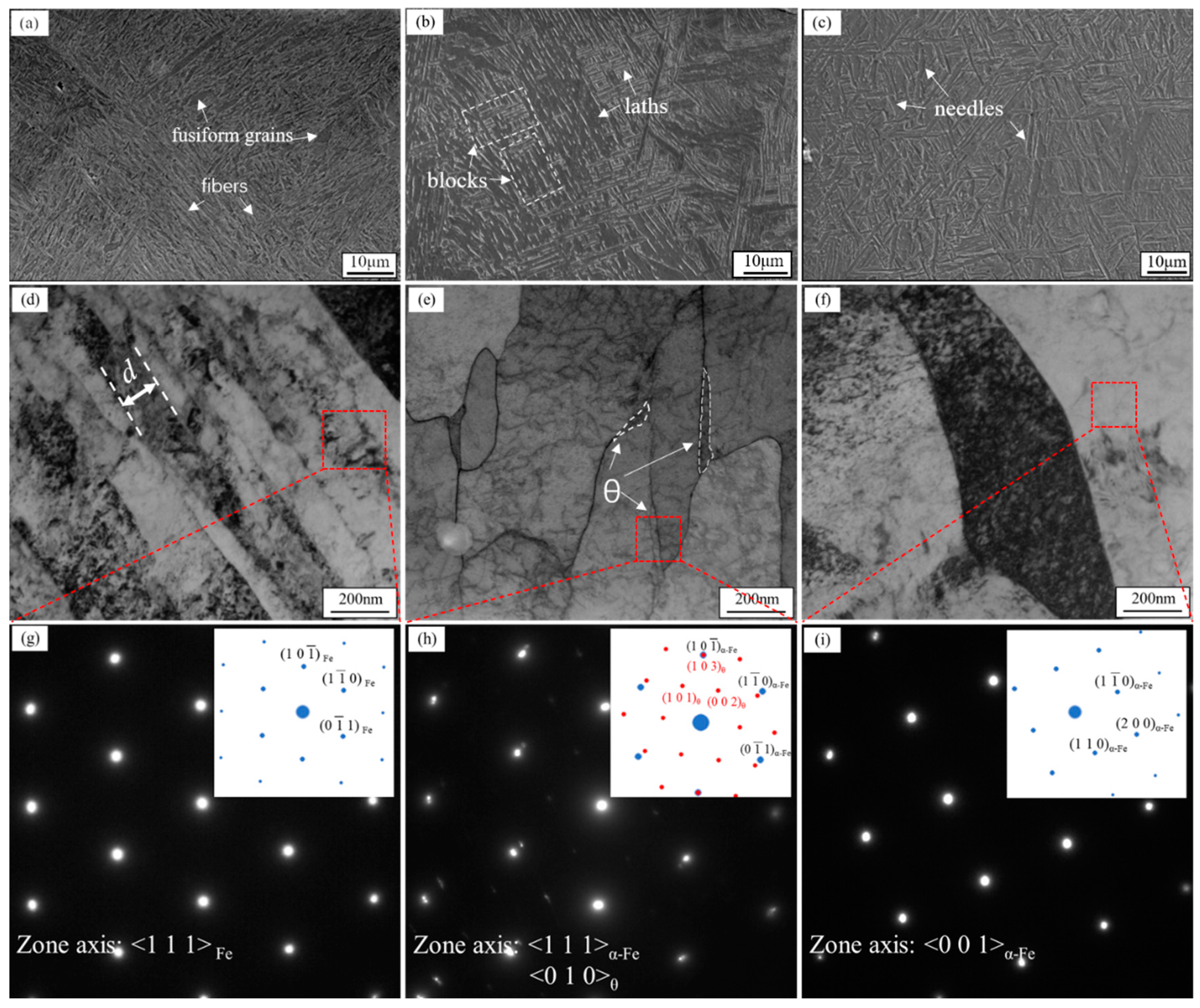
Based on SEM and TEM micrographs and SAED patterns from samples made by sub-rapid solidification, we identified three microstructures on the surface area of our sample, down to a depth of 200 μm: (1) lath martensite (M), consisting of fibers with fusiform grains randomly distributed between them; (2) upper bainite (UB), consisting of roughly parallel laths arranged within randomly oriented blocks; and (3) acicular ferrite (AF), consisting of needles with high-angle misorientations (Figure 2a–c). The average width of all grains (laths or needles) was less than 1 μm.
Martensite usually has a bct structure, one in which there is deformation in the a-axis and the c-axis. Our SAED patterns (Figure 2g) indicated a difference of about 0.4% between the interplanar distances of the (1 1 ¯ 0) plane and the (0 1 ¯ 1) plane, indicating the possible presence of lattice distortion. We used the following formulas to calculate the lattice distortion caused by C atoms in martensite [22]:
c = a0 + αp
a = a0βp
where c and a are lattice constants of martensite, a0 is the lattice constant of α-Fe (2.8664 Å), p is the carbon content (wt%), α = 0.116 ± 0.002, and β = 0.013 ± 0.002.
Given that the carbon content of our steel is 0.023 wt%, the value for c should be about 2.869 Å and the value for a should be about 2.866 Å. Thus, we calculated a difference of 0.05% between the interplanar distances of the (1 1 ¯ 0) plane (2.0266 Å) and the (0 1 ¯ 1) plane (2.0277 Å). In fact, the actual difference in martensite was higher than 0.05% as a result of carbon segregation in quenched low-carbon steel. Due to the difference of carbon solubility in γ-Fe and α-Fe, extra carbon was expelled to surrounding austenite (γ-Fe) when part of the austenite transformed into ferrite or bainitic ferrite during cooling. The carbon content of the enriched austenite could reach 5–6 times of the average carbon content of the steel [23]. The carbon-rich austenite then transformed diffusionlessly into martensite during quenching, resulting in a relatively high carbon content in the martensite. In our study, the carbon content in martensite would be about 0.14 wt% (6 times of 0.023 wt%). Thus, the calculated difference between the interplanar distances of (1 1 ¯ 0) and (0 1 ¯ 1) planes could reach 0.31%. It was similar to 0.4%, the value calculated according to SAED patterns. Thus, we concluded that it was a bct crystal structure in the area shown in Figure 2d.
The presence of martensite was confirmed by combining the lattice distortion from SAED results and the compared micrographs with the published images of lath martensite [7,24,25,26,27,28,29]. The ultrafine parallel laths in our TEM images were highly consistent with the known microstructures of lath martensite, the width of the laths (0.1–0.25 μm, averaged 128 nm) was well within the known range for martensite (0.1–0.5 μm) [28]. The straight grain boundaries between laths (shown in Figure 2d) that are a characteristic of martensite [29] are clearly visible in our TEM micrographs.
Our TEM micrographs of upper bainite showed the characteristic structure of lath-like ferrite with cementite (θ) between the laths (Figure 2e). Our SAED patterns indicated the presence of bcc α-Fe and the secondary phase strips of cementite with an Isaichev relationship ({110}α//{103}θ, <111>α//<010>θ) between the two phases (Figure 2h). The TEM micrographs of acicular ferrite showed relatively long and coarse grains (Figure 2f), and these grains were all indexed to be α-Fe (Figure 2i).
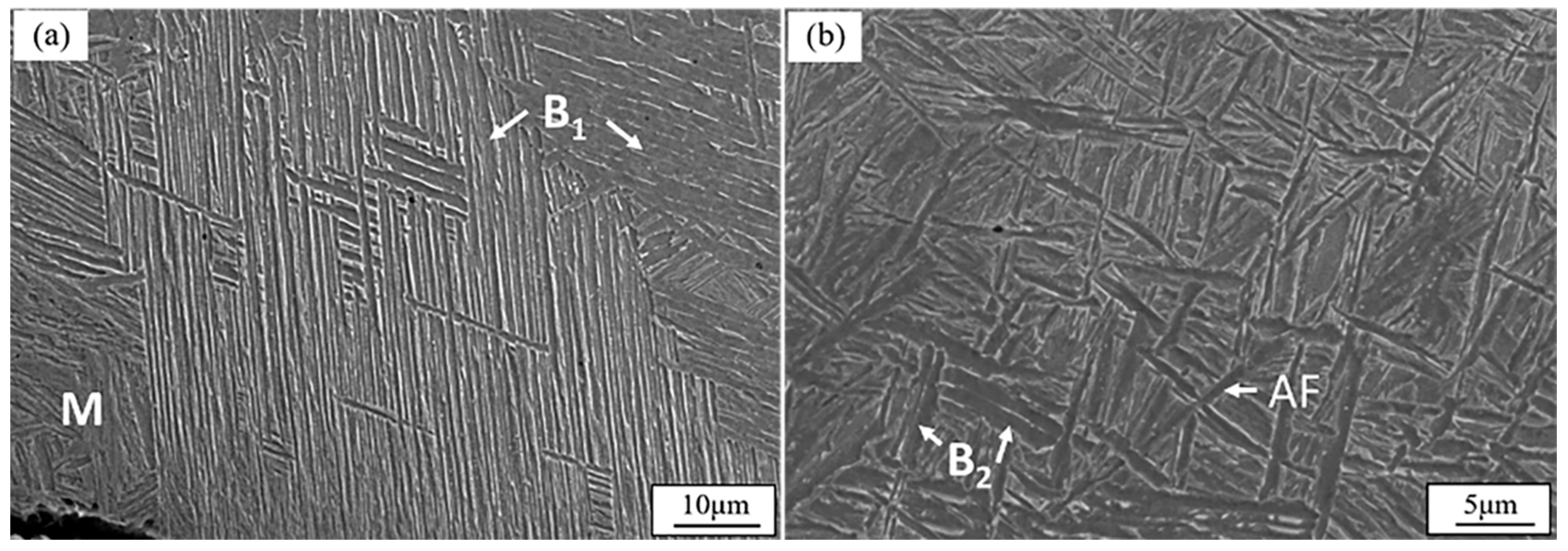
Three of the observed constituents mixed with one another in the surface layer. In the area of 0–50 μm depth, the microstructure consisted of lath martensite and upper bainite with large aspect ratios, which we called B1 (Figure 3a). In the area of 50–200 μm depth, the microstructure consisted of acicular ferrite and upper bainite with low aspect rations, which we called B2 (Figure 3b). B1 appeared as large blocks with over 15 roughly paralleled laths, and the length/width ratios of the laths were larger than 30. B2 appeared as an assortment of small blocks with several paralleled laths, and the length/width ratios of the laths were less than 10.

3.2. Nanohardness and Yield Strength

Since the thin surface layer differed greatly in hardness with the hardness in interior part of our steel, and the microstructure mixed one another in the thin layer, nanoindentation is the preferred method for testing surface mechanical properties in each microstructure.
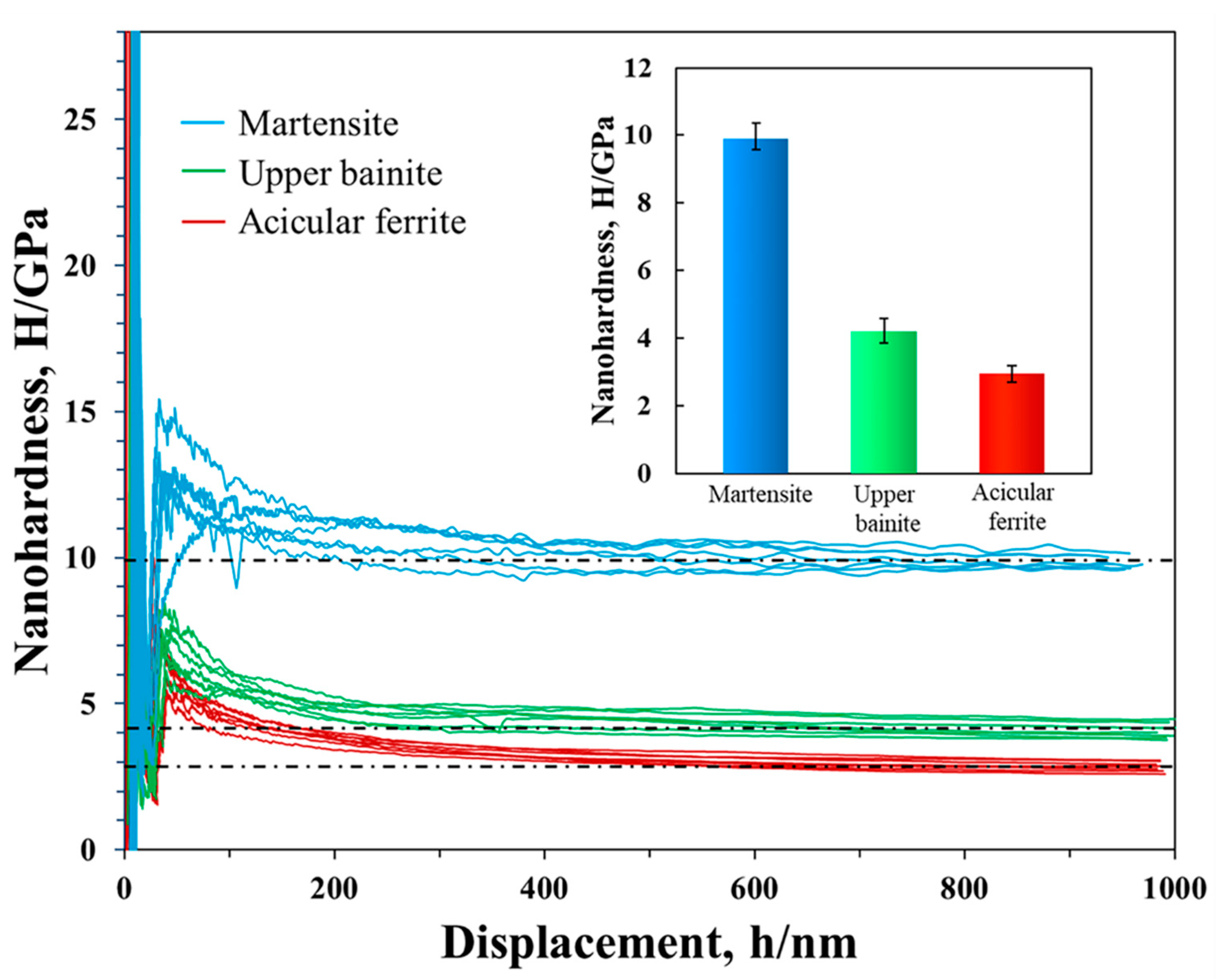
Based on data drawn from nanohardness–displacement curves, we knew that the average nanohardness was much higher for the martensite than for the ferrites: 9.87 ± 0.51 GPa for lath martensite, as opposed to 4.18 ± 0.39 GPa for upper bainite and 2.93 ± 0.30 GPa for acicular ferrite (Figure 4). High nanohardness in steel is usually associated with high carbon content. The carbon content (0.023 wt%) was considerably low in our steel matrix. Because of the existence of a mixed microstructure in the surface layer, the nanohardness of the martensite in our steel reached levels as high as those reported for steels with twenty times the carbon content (0.41 wt%) [30,31]. Ohmura et al. explained that their nanohardness results indicated a significant grain size effect in Fe-C martensite [31]. We thus assumed that, as Ohmura et al. suggested, the unusually high hardness of our lath martensite could be attributed to the fineness of the laths, whose width was only about 128 nm. This was nearly as low as 0.1 μm, the minimum width given by He et al. for martensite laths [28].
The nanohardness of the upper bainite in our steel fell well within the range of 3–5 GPa reported by other researchers [32,33,34]. On the other hand, the nanohardness reported for acicular ferrite by Shang et al., whose indentation tests were performed exclusively inside individual grains, was about 1.5 times lower than our findings [35]. Our value was close to that achieved in aged, alloyed low-carbon steels [36,37,38,39,40]. Our indentation tests were instead performed in a dot array that crossed grain boundaries, thus including the effect of those boundaries on dislocation glide. The average nanohardness of upper bainite was over 1 GPa higher than that of acicular ferrite, which we attributed mainly to the contribution of grain size. The average width was about 0.6 μm for upper bainite laths and about 0.8 μm for acicular ferrite needles. The precipitation strengthening effect of cementite also contributed to the higher hardness of upper bainite.
Using our tested average nanohardness values and the Equation (3) derived by Rodriguez et al. based on stress–strain testing, we calculated the yield strength in each microstructure of the surface layer [41]. It was about 2378 ± 123 MPa for lath martensite, 1007 ± 94 MPa for upper bainite, and 706 ± 72 MPa for acicular ferrite.
H = 4.15σY
where H is nanohardness and σY is yield strength.
Our low-carbon steel, with only 0.023% carbon content, proved to be able to sustain deformations without permanent deflection under a load of up to 2255 MPa. The high yield strength value of martensite particularly gave the surface layer exceptional resistance to abrasion to a degree that would be unachievable without additional heat treatment in other steels with similar carbon content.

4. Discussion

We created an illustration to show the distribution of the three microstructures in the surface layer of our sample (Figure 5). Our steel sheet experienced two key phase transformation stages during the cooling process: (1) liquid to solid transformation, (2) austinite to martensite or ferrite (room-temperature microstructure). The cooling rates during solidification, i.e., during liquid to solid transformation, were calculated to be about 900–1000 K/s at 0–50 μm depth and about 400–900 K/s at 50–200 μm depth. The high cooling rate at this stage resulted in a refined high-temperature microstructure in the surface area, such as an average austinite grain size of 152 μm. The cooling rates at the second stage were estimated to be about 50–100 K/s at 0–50 μm and about 10–30 K/s at 50–200 μm. According to the continuous cooling transformation (CCT) curve of a low-carbon steel [42], we deduced the phase transformation that occurred in the hard surface layer.
In the 0–50 μm depth area, the ferrite laths of upper bainite nucleated on austenite grain boundaries on the surface and grew inward. The carbon was expelled from bainitic ferrite into the surrounding austenite because of the difference in solubility of carbon in the two phases. With the further growth of bainitic ferrite laths, the supersaturated carbon between the laths in the same block precipitated in form of nanosized cementite strips, while the carbon expelled outside the block enriched the carbon content in surrounding austenite. The carbon-rich austenite subsequently transformed diffusionlessly into lath martensite as a result of a cooling rate of 50–100 K/s. Thus, the carbon content of the lath martensite was higher than the average carbon content (0.023%) in our sample, resulting in apparent lattice distortions in the crystal structure. A mixed microstructure of lath martensite and B1 upper bainite was formed.
In the 50–200 μm depth area, the cooling rate was about 10–30 K/s, which was in the acicular ferrite and bainitic ferrite transformation zone. Acicular ferrite nucleated and grew on inclusions inside austenite grains prior to bainitic ferrite, which effectively separated the austenite grains into small regions. The needles of acicular ferrite provided nucleation sites for bainite laths and also limited the growth of the laths [43]. This resulted in a mixed microstructure of acicular ferrite with B2 upper bainite laths in the 50–200 μm depth area.

5. Conclusions

1.
In the thin surface layer of sub-rapid-solidified low-carbon steel (0.023 wt% C), we confirmed the presence of not only upper bainite and acicular ferrite but also lath martensite. B1 upper bainite formed prior to lath martensite, and both of them were in 0–50 μm depth. B2 upper bainite formed after acicular ferrite, and both of them were in 50–200 μm depth. B2 upper bainite was shorter than B1.
2.
The unexpectedly high nanohardness of martensite in this low-carbon steel was 9.87 ± 0.51 GPa, equivalent to the nanohardness level reported for steel with twenty times the carbon content. This could be attributed to the fineness of the martensite laths with width of only 128 nm, which was nearly as low as the minimum width given for martensite. The nanohardness was 4.18 ± 0.39 GPa for upper bainite and 2.93 ± 0.30 GPa for acicular ferrite.
3.
Martensite at the surface had a yield strength of 2378 ± 123 MPa, substantially higher than upper bainite (1007 ± 94 MPa) or acicular ferrite (706 ± 72 MPa). The high yield strength of martensite in the surface layer gave the steel exceptional resistance to abrasion, to a degree that would be unachievable without additional heat treatment in other steels with similar carbon content.

Author Contributions

Conceptualization, S.Z., H.L. and K.H.; methodology, S.Z., H.L., H.X. and Y.X.; data analyses, H.L., H.X., S.Z., Y.X., J.X. and K.H.; original draft preparation, H.X.; review and editing, H.L., H.X., K.H. and Q.Z. All authors have read and agreed to the published version of the manuscript.

Funding

This work was supported by the Independent Research and Development Project of State Key Laboratory of Advanced Special Steel and the Shanghai Key Laboratory of Advanced Ferrometallurgy of Shanghai University (SKLASS 2019-Z009) and the Science and Technology Commission of Shanghai Municipality (No. 19DZ2270200). Part of the work was performed at the National High Magnetic Field Laboratory, which is supported by the National Science Foundation (DMR-1644779) and the State of Florida.

Acknowledgments

The JEM-ARM200cF TEM was supported by the Florida State University (FSU) research foundation. Thanks to the Instrumental Analysis & Research Center of Shanghai University for SEM, FIB and Nanoindentation. Thanks also to Mary Tyler for editing.

Conflicts of Interest

The authors declare no conflict of interest.

References

  1. Nisbett, E. Factors Affecting the Notch Toughness of Carbon and Low-Alloy Steel Forgings for Pressure Vessel and Piping Applications. J. Eng. Mater. Technol. 1978, 100, 338–347. [Google Scholar] [CrossRef]
  2. Ponsot, A.; Maynier, P.; Comon, J.; Bastien, P. Application of an Equivalence between Tempering Time and Temperature to the Study of the Hardness of Martensite for C and Low-Alloy Steels. Rev. Met. 1971, 68, 441–448. [Google Scholar] [CrossRef]
  3. Stokes, J.L. Magnetic Properties of Iron and Low Carbon Steel for Soft Magnet Applications. J. Test. Eval. 1981, 9, 354–358. [Google Scholar]
  4. Lee, J.H.; Jang, J.H.; Joo, B.D.; Son, Y.M.; Moon, Y.H. Laser Surface Hardening of Aisi H13 Tool Steel. Trans. Nonferrous Met. Soc. China 2009, 19, 137–140. [Google Scholar] [CrossRef]
  5. Li, H.G.; Wang, L.X.; Xiao, H.T.; Xu, J.L.; Zheng, S.B.; Zhai, Q.J.; Han, K. Hardening Low-Carbon Steels by Engineering the Size and Distribution of Inclusions. Metall. Mater. Trans. A 2019, 50, 336–347. [Google Scholar] [CrossRef]
  6. Krauss, G.; Thompson, S.W. Ferritic Microstructures in Continuously Cooled Low-and Ultralow-Carbon Steels. ISIJ Int. 1995, 35, 937–945. [Google Scholar] [CrossRef]
  7. Araki, T.; Enomoto, M.; Shibata, K. Microstructural Aspects of Bainitic and Bainite-Like Ferritic Structures of Continuously Cooled Low Carbon (<0.1%) Hsla Steels. Mater. Trans. JIM 1991, 32, 729–736. [Google Scholar] [CrossRef] [Green Version]
  8. Kitahara, H.; Ueji, R.; Tsuji, N.; Minamino, Y. Crystallographic Features of Lath Martensite in Low-Carbon Steel. Acta Mater. 2006, 54, 1279–1288. [Google Scholar] [CrossRef]
  9. Morito, S.; Huang, X.; Furuhara, T.; Maki, T.; Hansen, N. The Morphology and Crystallography of Lath Martensite in Alloy Steels. Acta Mater. 2006, 54, 5323–5331. [Google Scholar] [CrossRef]
  10. Smallman, R.E.; Ngan, A.H.W. Chapter 12—Steel Transformations; Elsevier Ltd.: Amsterdam, The Netherlands, 2014. [Google Scholar]
  11. Miyamoto, G.; Takayama, N.; Furuhara, T. Accurate Measurement of the Orientation Relationship of Lath Martensite and Bainite by Electron Backscatter Diffraction Analysis. Scr. Mater. 2009, 60, 1113–1116. [Google Scholar] [CrossRef]
  12. Cheng, L.; Bottger, A.; Dekeijser, T.H.; Mittemeijer, E.J. Lattice-Parameters of Iron-Carbon and Iron-Nitrogen Martensites and Austenites. Scr. Metall. Mater. 1990, 24, 509–514. [Google Scholar] [CrossRef]
  13. Han, K.; Van Genderen, M.; Böttger, A.; Zandbergen, H.; Mittemeijer, E. Initial Stages of Fe-C Martensite Decomposition. Philos. Mag. A 2001, 81, 741–757. [Google Scholar] [CrossRef]
  14. Jack, K.H. Structural Transformations in the Tempering of High-Carbon Martensitic Steels. J. Iron Steel Inst. 1951, 169, 26. [Google Scholar]
  15. Kajiwara, S.; Uehara, S.; Nakamura, Y. Structure Images of Unaged Martensite Containing a High-Carbon Content. Philos. Mag. Lett. 1989, 60, 147–153. [Google Scholar] [CrossRef]
  16. Naraghi, R.; Selleby, M.; Agren, J. Thermodynamics of Stable and Metastable Structures in Fe-C System. Calphad 2014, 46, 148–158. [Google Scholar] [CrossRef]
  17. Preciado, M.; Pellizzari, M. Influence of Deep Cryogenic Treatment on the Thermal Decomposition of Fe-C Martensite. J. Mater. Sci. 2014, 49, 8183–8191. [Google Scholar] [CrossRef]
  18. Bhadeshia, H.K.D.H.; Christian, J. Bainite in Steels. Metall. Trans. A 1990, 21, 767–797. [Google Scholar] [CrossRef]
  19. Ricks, R.; Howell, P.; Barritte, G. The Nature of Acicular Ferrite in Hsla Steel Weld Metals. J. Mater. Sci. 1982, 17, 732–740. [Google Scholar] [CrossRef]
  20. Bahl, S.; Suwas, S.; Ungàr, T.; Chatterjee, K. Elucidating Microstructural Evolution and Strengthening Mechanisms in Nanocrystalline Surface Induced by Surface Mechanical Attrition Treatment of Stainless Steel. Acta Mater. 2017, 122, 138–151. [Google Scholar] [CrossRef]
  21. Xin, Y.; Kynoch, J.; Han, K.; Liang, Z.; Lee, P.J.; Larbalestier, D.C.; Su, Y.-F.; Nagahata, K.; Aoki, T.; Longo, P. Facility Implementation and Comparative Performance Evaluation of Probe-Corrected Tem/Stem with Schottky and Cold Field Emission Illumination. Microsc. Microanal. 2013, 19, 487–495. [Google Scholar] [CrossRef] [PubMed]
  22. Kurdjumov, G.; Kaminsky, E. X-ray Studies of the Structure of Quenched Carbon Steel. Nature 1928, 122, 475–477. [Google Scholar]
  23. Clarke, A.J.; Speer, J.G.; Miller, M.K.; Hackenberg, R.E.; Edmonds, D.V.; Matlock, D.K.; Rizzo, F.C.; Clarke, K.D.; Moor, E.D. Carbon Partitioning to Austenite from Martensite or Bainite During the Quench and Partition (Q&P) Process: A Critical Assessment. Acta Mater. 2008, 56, 16–22. [Google Scholar]
  24. Zhang, P.; Chen, Y.; Xiao, W.; Ping, D.; Zhao, X. Twin Structure of the Lath Martensite in Low Carbon Steel. Prog. Nat. Sci. Mater. Int. 2016, 26, 169–172. [Google Scholar] [CrossRef] [Green Version]
  25. Li, Y.J.; Chen, D.; Liu, D.; Kang, J.; Yuan, G.; Mao, Q.J.; Misra, R.D.K.; Wang, G.D. Combined Thermo-Mechanical Controlled Processing and Dynamic Carbon Partitioning of Low Carbon Si/Al-Mn Steels. Mater. Sci. Eng. A 2018, 732, 298–310. [Google Scholar] [CrossRef]
  26. Morito, S.; Ohba, T.; Maki, T. Comparison of Deformation Structure of Lath Martensite in Low Carbon and Ultra-Low Carbon Steels. Mater. Sci. Forum 2007, 558–559, 933–938. [Google Scholar] [CrossRef]
  27. Maki, T. Morphology and Substructure of Martensite in Steels. Gangtie 2012, 2, 34–58. [Google Scholar]
  28. He, B.B.; Huang, M.X. Revealing the Intrinsic Nanohardness of Lath Martensite in Low Carbon Steel. Metall. Mater. Trans. A 2014, 46, 688–694. [Google Scholar] [CrossRef]
  29. Bhadeshia, H.; Honeycombe, R. Steels: Microstructure and Properties; Butterworth-Heinemann: Oxford, UK, 2017. [Google Scholar]
  30. Ohmura, T.; Hara, T.; Tsuzaki, K. Evaluation of Temper Softening Behavior of Fe–C Binary Martensitic Steels by Nanoindentation. Scr. Mater. 2003, 49, 1157–1162. [Google Scholar] [CrossRef]
  31. Ohmura, T.; Tsuzaki, K.; Matsuoka, S. Nanohardness Measurement of High-Purity Fe–C Martensite. Scr. Mater. 2001, 45, 889–894. [Google Scholar] [CrossRef]
  32. He, B.B.; Zhu, K.; Huang, M.X. On the Nanoindentation Behaviour of Complex Ferritic Phases. Philos. Mag. Lett. 2014, 94, 439–446. [Google Scholar] [CrossRef]
  33. Choi, B.W.; Seo, D.H.; Jang, J.I. A Nanoindentation Study on the Micromechanical Characteristics of Api X100 Pipeline Steel. Met. Mater. Int. 2009, 15, 373–378. [Google Scholar] [CrossRef]
  34. Choi, B.W.; Seo, D.H.; Yoo, J.Y.; Jang, J.I. Predicting Macroscopic Plastic Flow of High-Performance, Dual-Phase Steel through Spherical Nanoindentation on Each Microphase. J. Mater. Res. 2011, 24, 816–822. [Google Scholar] [CrossRef]
  35. Shang, C.J.; Liang, X.; Wang, X.M.; He, X.L.; Liu, H. The Nanohardness of Acicular Ferrite and Bainitic Ferrite in Low Carbon Microalloying Steel. In Materials Science Forum; Trans Tech Publications Ltd.: Zurich, Switzerland, 2007. [Google Scholar]
  36. McFarlan, W.; Taylor, H.L. Properties and Applications of Low Carbon Martensitic Steel Sheets. SAE Trans. 1969, 78, 104. [Google Scholar]
  37. McNitt, L.F. Application of Low-Carbon, High-Strength Steels. Des. News 1970, 25, 150. [Google Scholar]
  38. Shen, Z.Y.; Wang, B.L.; Liang, G.F.; Zhang, Y.H.; Han, K.; Song, C.J. Grain Boundary Pop-in, Yield Point Phenomenon and Carbon Segregation in Aged Low Carbon Steel. ISIJ Int. 2018, 58, 373–375. [Google Scholar] [CrossRef] [Green Version]
  39. Pohl, F. Pop-in Behavior and Elastic-to-Plastic Transition of Polycrystalline Pure Iron during Sharp Nanoindentation. Sci. Rep. 2019, 9, 1–12. [Google Scholar] [CrossRef] [Green Version]
  40. Li, Z.M.; Li, X.; Yang, L.; Shen, Z.Y.; Wang, B.L.; Zhao, S.L.; Liang, G.F.; Song, C.J. Effect of Coiling and Annealing Temperatures on Yield Point Behavior of Low-Carbon Steel. J. Iron Steel Res. Int. 2020, 27, 325–333. [Google Scholar] [CrossRef]
  41. Rodríguez, R.; Gutierrez, I. Correlation between Nanoindentation and Tensile Properties: Influence of the Indentation Size Effect. Mater. Sci. Eng. A 2003, 361, 377–384. [Google Scholar] [CrossRef]
  42. Jun, H.J.; Kang, J.S.; Seo, D.H.; Kang, K.B.; Park, C.G. Effects of Deformation and Boron on Microstructure and Continuous Cooling Transformation in Low Carbon Hsla Steels. Mater. Sci. Eng. A 2006, 422, 157–162. [Google Scholar] [CrossRef]
  43. Yang, J.; Huang, C.; Huang, C.; Aoh, J. Influence of Acicular Ferrite and Bainite Microstructures on Toughness for an Ultra-Low-Carbon Alloy Steel Weld Metal. J. Mater. Sci. Lett. 1993, 12, 1290–1293. [Google Scholar] [CrossRef]
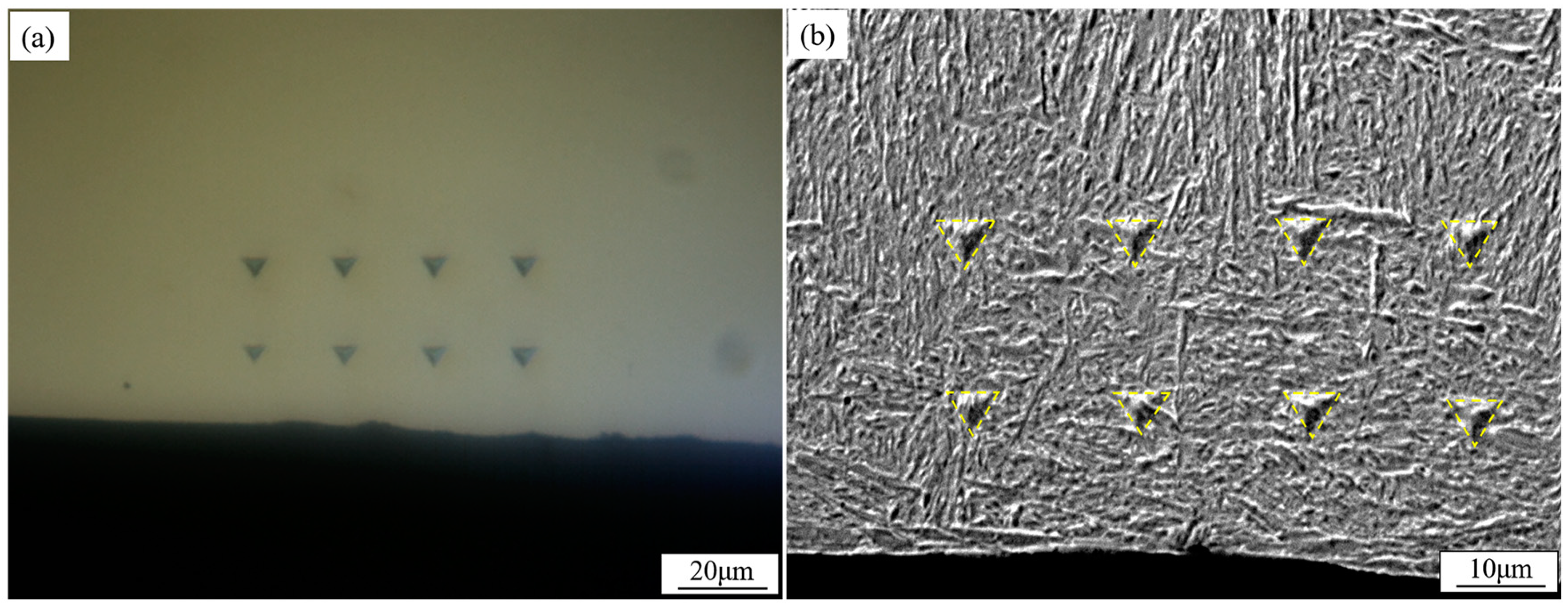
Figure 1. Dot array of indentations: (a) in a polished plane, the nanoindentations were detected; (b) in an etched plane, the nanoindentations crossed the grain boundaries in a microstructure.
Metals 10 00995 g001
Figure 2. Microstructures found at 0–200 μm depth of the sample surface. (a) SEM image of martensite. (b) SEM of upper bainite. (c) SEM of acicular ferrite. (d) TEM image of martensite with the width of laths indicated between white dashed lines. (e) TEM of upper bainite with cementite outlined in white dashed lines. (f) TEM of acicular ferrite. (g) SAED pattern of martensite with a zone axis of <111>. (h) SAED of upper bainite with a zone axis of <111> and cementite with a zone axis of <010>. (i) SAED of acicular ferrite with a zone axis of <001>.
Metals 10 00995 g002
Figure 3. SEM micrographs of the mixed microstructures in the surface layer. (a) Mixed microstructure of lath martensite and B1 blocks of upper bainite in the 0–50 μm area. (b) Mixed microstructure of acicular ferrite and B2 blocks of upper bainite in the 50–200 μm area.
Metals 10 00995 g003
Figure 4. Nanohardness–displacement curves of the three microstructures. Average hardness for each microstructure was drawn from the flat lines in the displacement range between 600 and 1000 nm. The average nanohardness and its error value in each microstructure were shown in the top-right corner.
Metals 10 00995 g004
Figure 5. Schematic illustration of mixed microstructure in the surface layer.
Metals 10 00995 g005
Table 1. Chemical compositions.
ElementCMnSiTiFe
Mass Fraction/%0.0230.640.210.016Balance