Article

The Forming Control Method of Multi-Track Laser Cladding on Curved Surface

1
School of Mechanical and Automotive Engineering, Fujian University of Technology, Fuzhou 350118, China
2
School of Engineering + Technology, Western Carolina University, Cullowhee, NC 28723, USA
*
Author to whom correspondence should be addressed.
Metals 2020, 10(8), 1109; https://doi.org/10.3390/met10081109
Submission received: 11 July 2020 / Revised: 4 August 2020 / Accepted: 14 August 2020 / Published: 18 August 2020

Abstract

:
This paper investigated the correlation between the processing parameters and the properties of clad deposited by laser cladding on a curved surface. Mathematical models relating the processing parameters (laser power, scanning speed, gas flow, and overlap ratio) and clad properties (flatness ratio and pore area) were established by central composite design. Analysis of variance and experimental validation confirmed the validity of the models. The results indicated that the flatness ratio was negatively influenced by the larger scanning speed, gas flow, and overlap ratio, while the pore area was enlarged by the increasing of scanning speed, and increasing the overlap ratio lead to the pore area reducing at first and then increasing. Optimized processing parameters were obtained under the target of maximizing the flatness ratio and minimizing the pore area. The developed mathematical models enabled predicting the flatness ratio and pore area with optimized processing parameters. The validation experimental result verified the prediction accuracy of the models and displayed target improvement compared with the original central composite design. The results provide theoretical guidance in multi-track laser cladding on a curved surface for the prediction and control of the geometric characteristics of the coating and the optimization of the processing parameters. This research outcome provides guidance for the coating deposition application in crankshaft surface coating or surface restoration, rotary parts coating deposition, or complex shape tool manufacturing. It also forms the fundamental basis for the extensive application of multi-track laser cladding on curved substrates in the additive manufacturing industry.

1. Introduction

Laser cladding utilizes a high-energy laser beam to irradiate the cladding material and substrate, causing rapid melting and solidification in the cladding zone. Afterwards, a metallurgical bonded layer with a low dilution rate was formed on top of the substrate, which improved the properties of the substrate [1]. Compared with other surface modification technologies, such as thermal spraying and electroplating, laser cladding overcomes the issues of hot deformation, pore formation, poor bonding, etc. [2,3,4]. Therefore, laser cladding has been widely used in aerospace, automotive, mold, and roll industries. The usage of laser cladding has also been extended into the restoration and remanufacturing of shaft parts with the improvement of cladding properties [5,6]. Laser cladding is a complex process, because it involves the interaction between different elements, such as laser power and cladding powder, cladding powder and substrate, and among different parameters [7,8]. Therefore, mathematical models that can guide the intercorrelation between processing parameters and clad geometric characteristics are beneficial in the applications to reduce a large amount of experiments.
In the discovery of variation in the geometric characteristics of the cladding layer caused by the influence of processing parameters, Mohammad et al. deposited Ti–6Al–4V powder alloy on Ti–6Al–4V substrate using the laser cladding process. They investigated the influence of processing parameters on single-track laser cladding and built the model between processing parameters and clad geometric characteristics by linear regression. The model was validated by the analysis of related coefficients and residuals [7]. Similarly, Erfanmanesh et al. optimized the processing parameters from an empirical–statistical viewpoint in the laser cladding of WC-12Co powder on AISI 321 steel substrate [9]. According to the energy density per unit of molten pool volume, Shi et al. combined energy and mass conservation law, which established mathematical models revealing the relationship between the cladding layer geometric characteristics (clad width, height, and cross-section area) and processing parameters (laser power, scanning velocity, and wire feeding speed) [10]. Liu et al. examined a full factorial design of experiments, and they studied the relationship between the processing parameters and geometrical characteristics of a single-track clad. A nonlinear model was fitted and verified to describe the relationship between the processing parameters and geometry parameters [4]. Ansari et al. utilized regression analysis and discussed the correlations between main processing parameters (laser power, scanning speed, powder feeding rate) and geometrical characteristics (clad width, height, penetration depth, dilution, and wetting angle) in single-track laser cladding. The prediction accuracy was confirmed by analyzing the correlation coefficient and the residuals [11].
In the application of response surface methodology, Farahmand et al. used central composite design and response surface methodology to study the influence of laser power, powder feeding rate, and scanning speed on the clad height, heat-affected zone depth, and microhardness of the cladding layer. Models relating the output properties and the input processing parameters were built by multiple regression analysis and confirmed by experimental validation [12]. Saqib et al. conducted a full factorial central composite design complying with response surface methodology to study the impact of processing parameters on geometric characteristics during single-track laser cladding 420 stainless steel on the substrate of cold rolled structural steel [13].
In the application of laser cladding on a curved surface, Calleja et al. optimized the laser cladding tool path and processing parameters for 5-axis laser cladding with the goal of optimizing the cladding efficiency, wetting angle, clad height, and width [14]. Tabernero et al. studied the optimal parameters in 5-axis laser cladding on a semispherical surface. The optimized processing parameters presented desired properties in the cladding layer [15].
Current research studies are focusing on the correlation between processing parameters and clad properties in single or multi-track laser cladding on plane substrate [16]. There is a lack of discovery in laser cladding on curved surfaces, because the investigations have primarily focused on the tool path planning on irregular curved surfaces. Although these studies provide a certain level of theoretical guidance, there remains a lack of actual application. Due to the difference between the curved surface and the plane surface, the surface tension force and formation mechanism of molten pool have significant influence on the cladding process [17]. During clad deposition on a curved surface with curved paths, the curved substrate is in motion, where the movement of substrate has a significant impact on the focusing of the delivered cladding powder. Additionally, the convection in the molten pool and forming mechanism in the curved substrate while moving cause a large differentiation in the laser cladding on a plane substrate. Meanwhile, the influence of processing parameters on the clad properties in multi-track laser cladding is more complex than single-track laser cladding. On the basis of acquiring an outstanding metallurgical bonded layer, obtaining favorable surface flatness and cross-section quality are required in the investigation of processing parameters’ variation in multi-track laser cladding on curved surfaces. This study applied central composite design in response surface methodology, studied the influence of laser power, scanning speed, gas flow, and overlap ratio on the clad properties, established mathematical models relating processing parameters and clad properties, and achieved the prediction and control of multi-track laser cladding on a curved surface.

2. Materials and Methods

This study was designed in the background of crankshaft restoration. The AISI/SAE 1045 steel round rod was selected as the substrate, with a length of 40 mm and diameter of 70 mm. The laser cladding powder was W6Mo5Cr4V2 high-speed steel powder produced by Chengdu Huayin Powder Technology CO., LTD, Chengdu, China. The elemental composition of W6Mo5Cr4V2 high-speed steel powder is shown below in Table 1.
Figure 1 shows the laser cladding system used in this study, which consists of four sub-systems: laser generating, laser deposition, powder feeding, and programmable logic control. The programmable logic controller computer system produced by Mitsubishi, Japan managed the whole system operation during laser cladding. The laser beam was generated by an IPG Photonic YLS-3000 laser generator and controlled by IPG Photonic SX14-012PULSE laser pulse control (IPG Photonic, Burbach, Germany). Then, the laser beam was transmitted into a Lasermech FDH0273 laser-cladding nozzle with a 300 mm focal length (Lasermech, Novi, MI, USA). Simultaneously, the cladding powder was delivered onto the substrate by the Songxing CR-PGF-D-2 powder feeding system (Songxing, Fuzhou, China). The FANUC M-710iC/50 industrial robot (FANUC, Yamanashi, Japan) and a three-jaw universal chuck were utilized to control the movement of substrate during laser cladding. A Sanhe Tongfei TFLW-4000WDR-01-3385 water cooling system (Sanhe Tongfei, Sanhe, China) was equipped to protect the devices in the system. Argon gas serving as the carrier and protective gas was used during the laser cladding process.
To prepare for laser cladding, the surface of the AISI/SAE 1045 steel round rod was cleaned with acetone. The W6Mo5Cr4V2 high-speed steel powder was dried in a vacuum dryer at 120 °C for 30 min to prevent clogging during powder delivery. The experimental design in this study utilized a central composite design (CCD) module in response surface methodology (RSM) with Design-Expert software (version 10.0.4.0, Stat-Ease, Minneapolis, MN, USA). RSM is an optimization methodology combining experimental design and mathematical modeling, which can establish a rational mathematical model between input variables and output responses. Besides, the CCD module is able to provide maximal predicting accuracy and minimal overall error with a small amount of experimental runs [18]. Through a literature review and previous studies, it was found that the factors of laser power, scanning speed, gas flow, and overlap ratio had a significant influence on the properties of the cladding layer [16,19]. Thus, the input variables to be investigated in this study were the following adjustable processing parameters: laser power (LP), scanning speed (SS), gas flow (GF), and overlap ratio (OR). Each variable was assigned as one factor, which had five levels as 0, ±1, ±2 in the CCD design. The four-factor five-level CCD matrix is shown in Table 2.
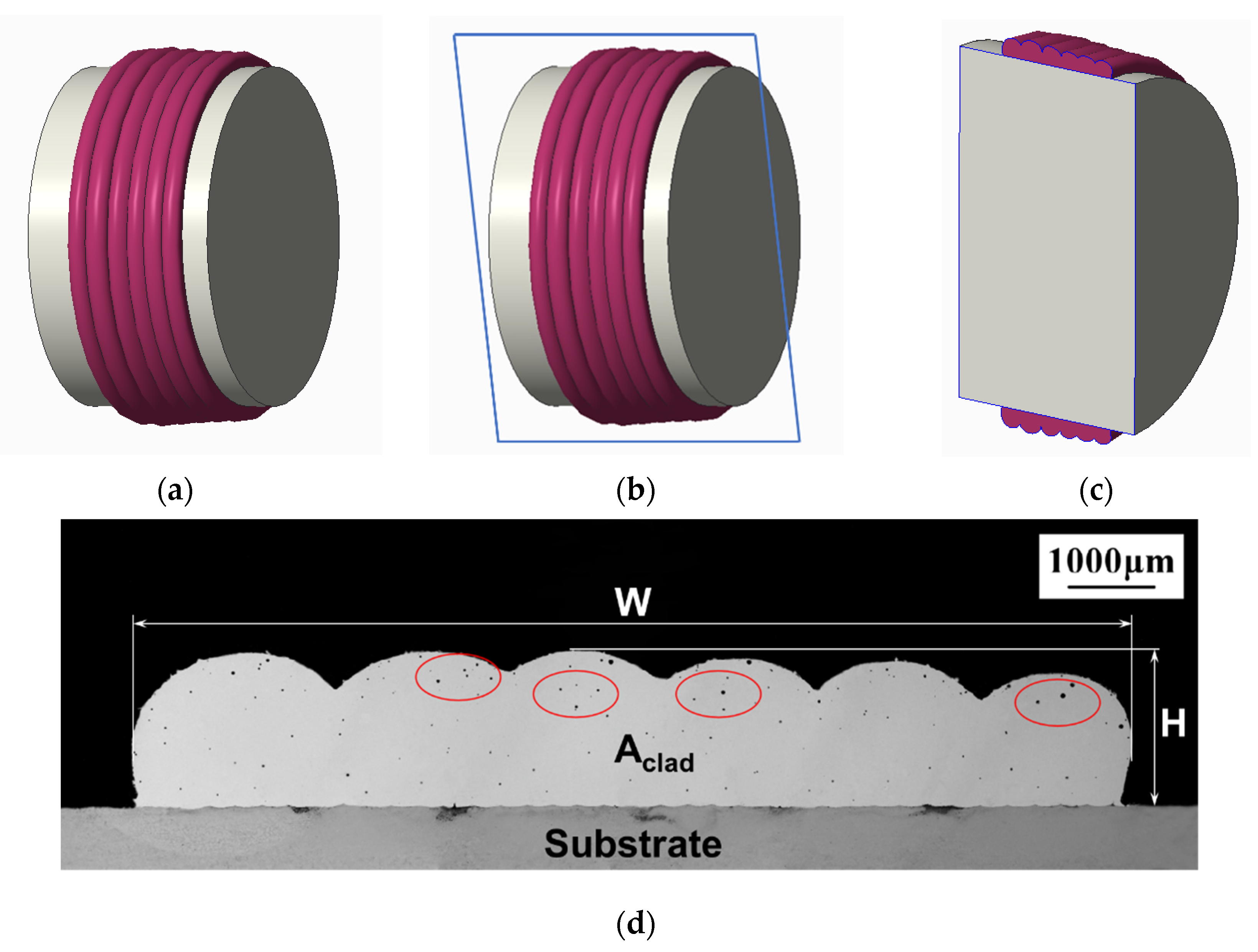
The selected responses in this study were the flatness ratio and pore area. After the completion of laser cladding, the samples (Figure 2a) were cut linearly at the location shown in Figure 2b to obtain the cross-section views of the clad coated on the substrate (Figure 2c). An example of the microstructure in the cross-section of the clad coated on the substrate is shown in Figure 2d. All the relevant geometric measurements on the cross-section were obtained by a KH-1300 3D microscope (Hirox Co Ltd., Tokyo, Japan). Equation (1) was used to calculate the flatness ratio, where Aclad represents the overall cross-section area of the clad deposited on the substrate, W stands for the total width including all the cladding tracks, and H is the maximum height of a cladding track among all the cladding tracks [20,21,22]. As shown in Figure 2d, each pore area (Ai) in the cross-section was measured by the KH-1300 3D microscope (Hirox Co Ltd., Tokyo, Japan). The overall pore area was obtained by cumulative summing of all the pores in the cross-section, following Equation (2), where n was assumed to be the total number of pores in the cross-section. A total of 30 experimental runs were conducted based on the CCD design; the corresponding processing parameters setup in different levels are shown in Table 3. The corresponding responses of the flatness ratio and pore area for each run are also displayed in Table 3.
Flatness   Ratio = A c l a d W × H
Pore   Area = 1 n A i

3. Results and Discussion

3.1. Significance Test and Analysis of Variance

A test of significance was conducted to determine which model is applicable to interpret the relation between the input variables and the selected responses. The significance level was set at 0.05. Test of significance results regarding the flatness ratio and the pore area are shown in Table 4 and Table 5, respectively. The two-factor interaction model was suggested for the flatness ratio and the quadratic model was suggested for the pore area. These were determined by their sequential p-value (smaller than 0.0001) and lack of fit p-value (larger than 0.05), which indicated the remarkable fitting accuracy [23]. Hence, the mathematical models for the flatness ratio and pore area were established as Equations (3) and (4), respectively.
Flatness   Ratio = 0.44413 + 8.4603 × 10 4 × LP + 0.31281 × SS 3.541 × 10 5 × GF 0.021093 × OR 2.02077 × 10 4 × LP × SS + 1.92487 × 10 5 × LP × OR 1.18707 × 10 3 × SS × OR
Pore   Area = 1.78711 8.09771 × 10 4 × LP + 0.021837 × SS 5.49104 × 10 4 × GF 0.063098 × OR + 2.54938 × 10 5 × LP × OR + 1.56188 × 10 5 × GF × OR + 1.80771 × 10 4 × OR 2
The analysis of variance (ANOVA) results for the flatness ratio and pore area are shown in Table 6 and Table 7. Statistical significance was indicated for the flatness ratio model from the p-value in Table 6. Compared to the significance level 0.05, the p-value of model was less than 0.0001 and the lack of fit p-value was 0.0739. In addition, the signal-to-noise ratio (Adequate Precision) was 32.267, which was larger than 4. Moreover, all the determination coefficients (R-Squared, Predicted R-Squared, and Adjusted R-Squared) were close to 1, and the difference between Adjusted R-Squared and Predicted R-Squared was less than 0.2 [16,22]. All of these indicated the rationality of the flatness ratio model with favorable fitting accuracy. Besides, it can be seen that the flatness ratio was significantly affected by the following factors: scanning speed, gas flow, overlap ratio, the interaction of laser power and scanning speed, the interaction of laser power and overlap ratio, and the interaction of scanning speed and overlap ratio.
Similarly, the pore area model selection also exhibited promising accuracy to interpret the relation between input variables and the pore area in the clad. The following factors were found to have a significant influence on the pore area: scanning speed, gas flow, overlap ratio, the interaction of laser power and overlap ratio, the interaction of gas flow and overlap ratio, and the quadratic term of overlap ratio.

3.2. Analysis of Flatness Ratio

Figure 3a was the normal probability plot of residuals in the 30 runs. Each dot represented the residual for a run in the experiment; all the residuals nearly fell on a straight line, which implied that the residuals were distributed normally. Figure 3b showed the comparison between the actual experimental flatness ratio and the model predicting value. The gray line in Figure 3b served as the reference line where the actual and predicted value are the same. The close distribution to the reference line demonstrated a small-scale error predicted by the flatness ratio model. Hence, the fitting adequacy of the flatness ratio model was further verified by the diagnostic diagrams.
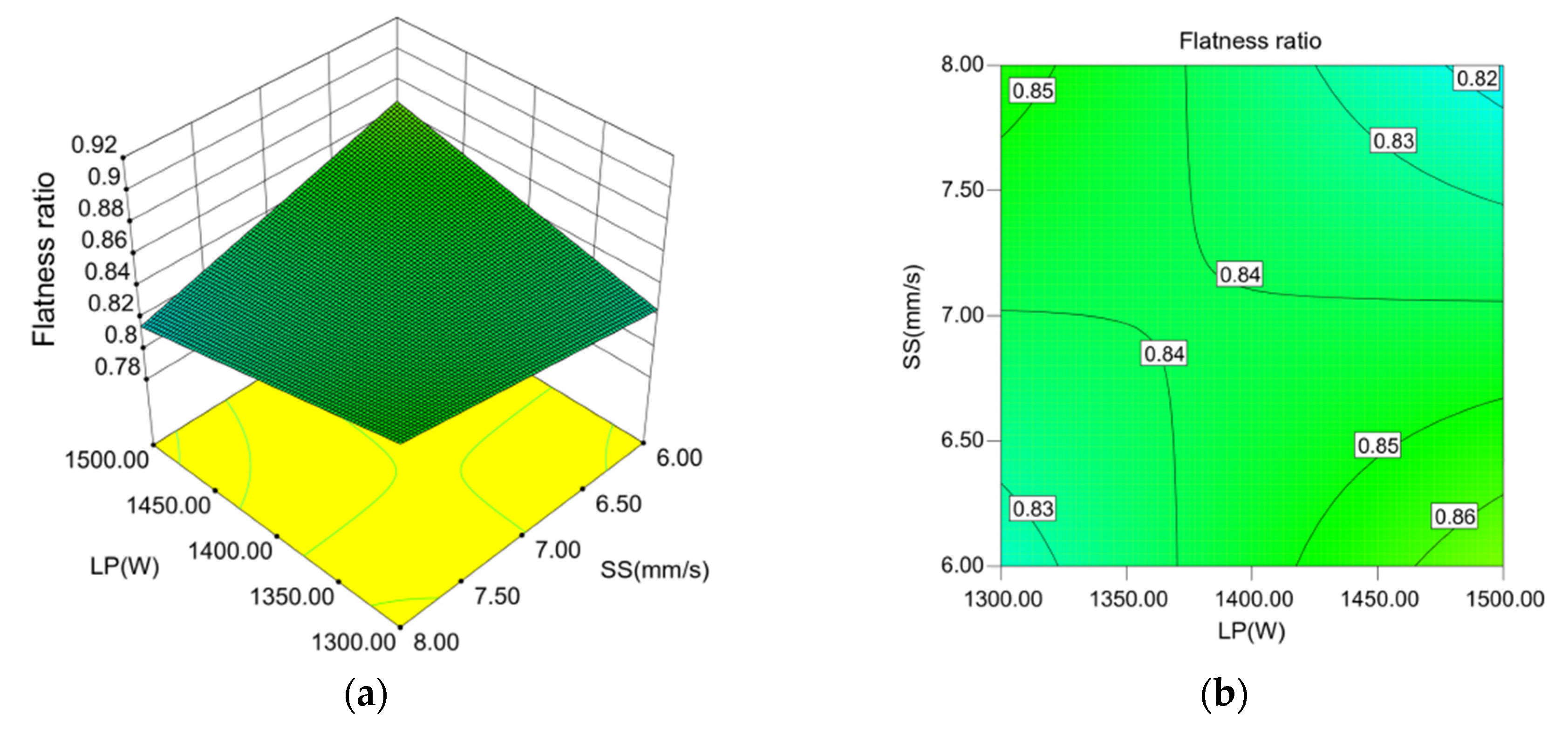
Figure 4 displayed how the flatness ratio was affected by the interaction between laser power and scanning speed in the form of the response surface and its contour line. During the laser cladding process, the laser power controlled the effective laser energy transmitting into the cladding zone, while the scanning speed determined the duration of the laser energy irradiating on the molten pool and powder feeding. When the laser power was relatively low in the studied range (1300–1380 W), the flatness ratio displayed a slight decrease with the reducing scanning speed (8 to 7 mm/s). Since the reduced scanning speed caused the nozzle to stay for an extended duration on top of the cladding zone, more powder was fed into the cladding zone. The delivered powder was unable to be completely melted due to the low laser power introduced. Since the effective energy absorbed by the cladding zone was relatively low as well, the convection effect in the molten pool was limited. Under the same overlap ratio, the height difference caused by overlapping between two adjacent tracks was unable to be flattened. Thus, the flatness ratio was reduced slightly. Under the relatively high laser power in the studied range (1380–1500 W), the flatness ratio showed a significant increase by reducing the scanning speed. Since a large laser power promoted cladding powder melting and the irradiation area on the curved surface was relatively larger than the flat substrate surface, the reduced scanning speed prolonged the laser energy irradiation and expanded the cladding zone. Under the effect of tension and gravity on the curved substrate, the melted cladding zone flattened the height difference between two adjacent tracks, leading to an increased flatness ratio.
Figure 5 displayed the influence of laser power and overlap ratio interaction on the flatness ratio in the form of the response surface and its contour line. The flatness ratio was showing the trend of decreasing when both the laser power and overlap ratio were setup to increase. With the increased laser power, the effective energy absorbed by the molten pool also increased. Hence, the molten pool was expanded on the curved substrate, leading to more powders melting and causing a larger cross-section area for each track. Simultaneously, an increased overlap ratio led to a larger overlap between adjacent cladding tracks in the stacking area. Thus, the height difference between adjacent cladding tracks was aggravated, causing the overall flatness ratio to reduce.
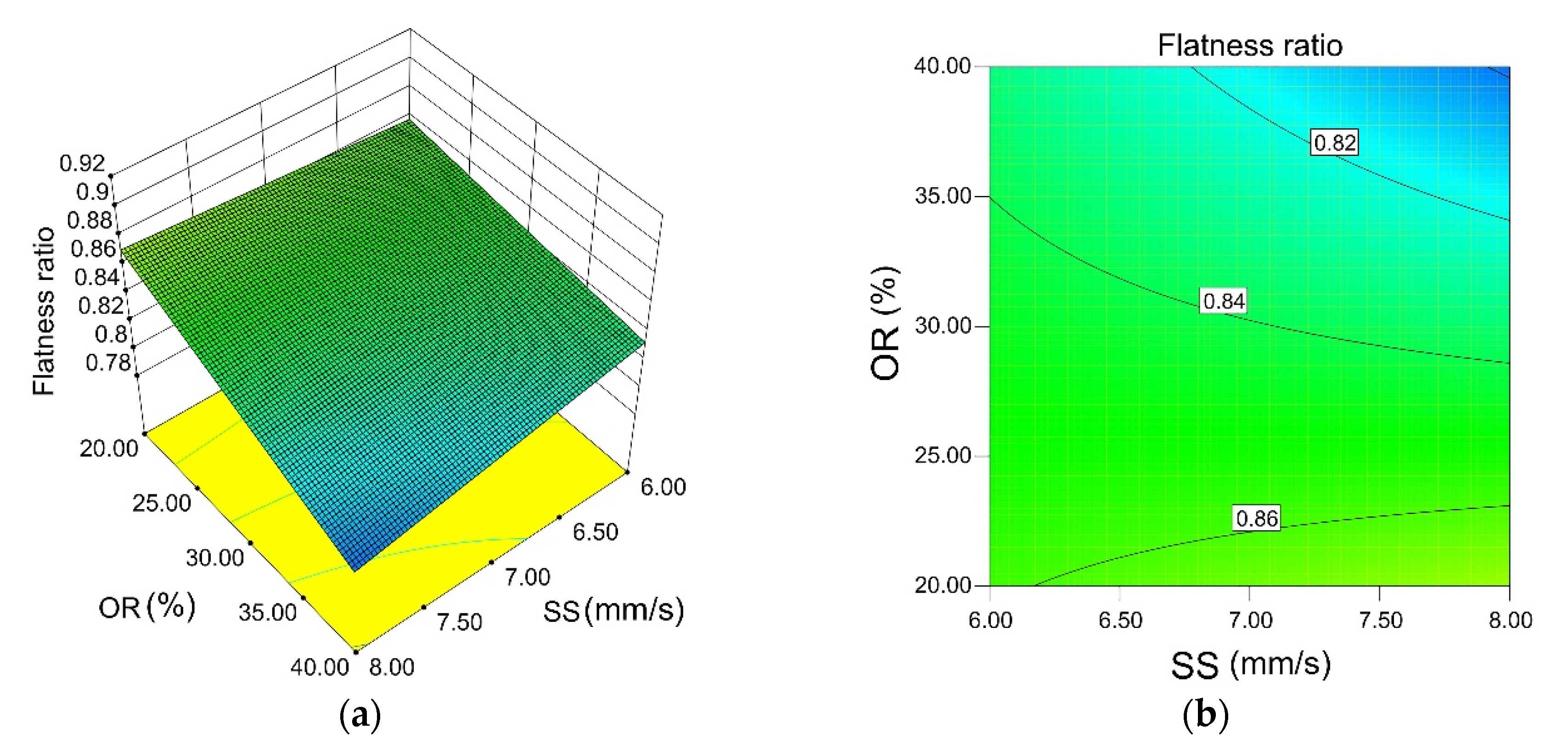
Figure 6 showed the influence of scanning speed and overlap ratio interaction on the flatness ratio in the form of the response surface and its contour line. It was observed that with the increasing scanning speed and overlap ratio, the flatness ratio tended to decrease, since a larger scanning speed denoted a shorter duration of laser irradiation. Subsequently, the molten pool absorbed less energy, resulting in a reduced convection effect in the molten pool. Therefore, the flow of melted cladding powder in the cladding zone was weakened, leading to the ineffectiveness of flattening the height difference between adjacent cladding tracks due to the increasing overlap ratio.
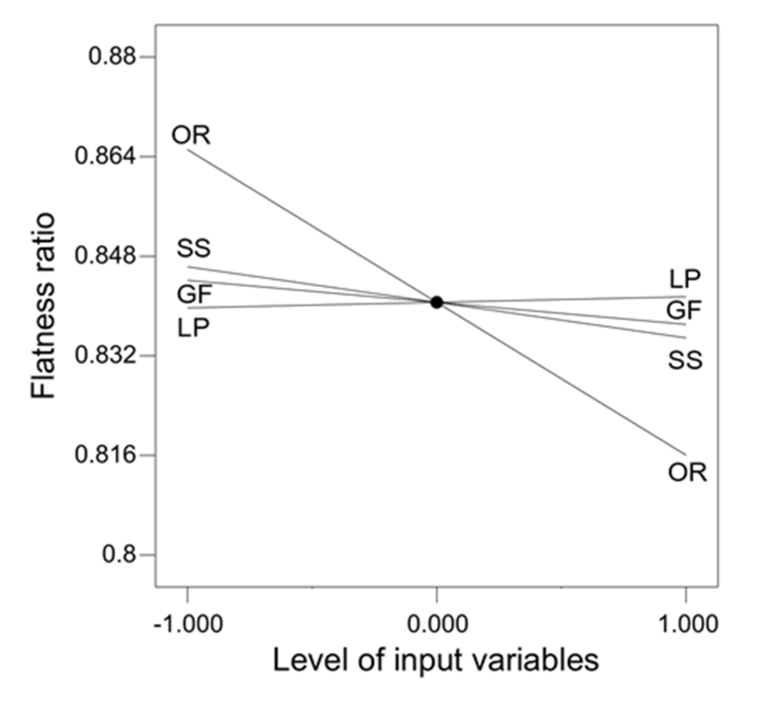
Figure 7 was obtained by averaging the flatness ratio for each processing parameter at selected levels. It showed the influence of each processing parameter on the flatness ratio individually. During the laser cladding on a curved surface, the overlap ratio implied the most significant impact on the flatness ratio. To obtain a higher flatness ratio in the clad, a lower overlap ratio was suggested due to the negative correlation displayed in Figure 7. Besides, the scanning speed and gas flow also denoted a negative correlation with the improvement of flatness ratio, while the laser power showed a negligible influence on the flatness ratio.

3.3. Analysis of Pore Area

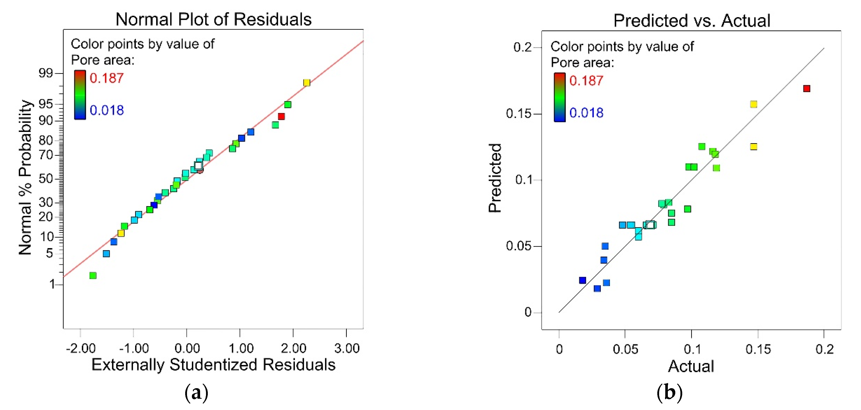
The normal probability plot of the studentized residuals shown in Figure 8a was an important diagnostic. The normality assumption was attributed, as the residual plot was following a straight line approximately. Figure 8b further verified the established pore area model, where the predicted pore area computed by Equation (4) and the actual experiment measurement of pore area were plotted. The small-scale offset from the reference line in Figure 8b indicated the remarkable fitting accuracy of the pore area model.
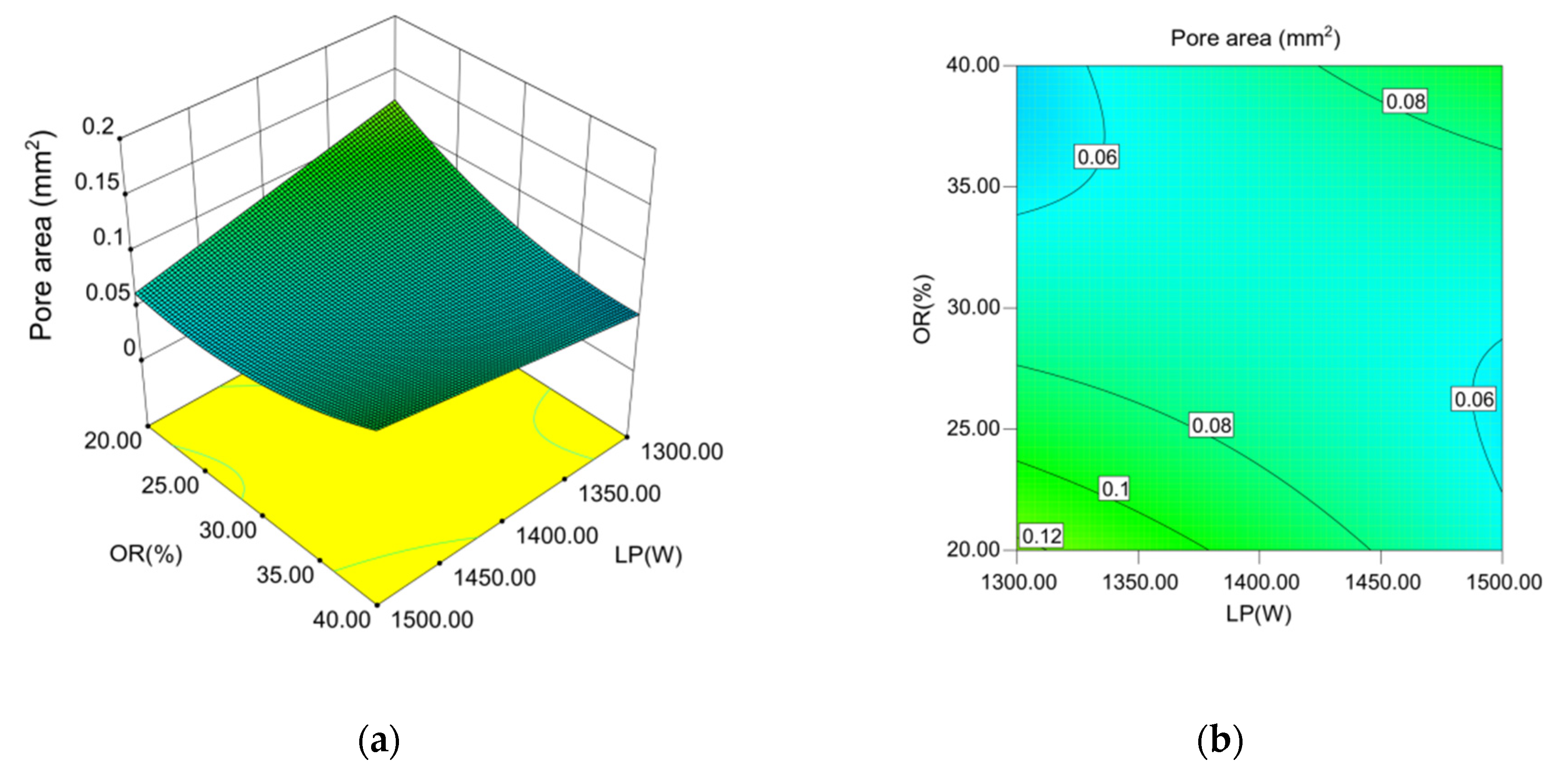
As shown in the response surface and its contour line in Figure 9a,b, when increasing the laser power and overlap ratio, the pore area displayed a trend of decreasing at first and then increasing afterwards. With the increased laser power, the energy received by the molten pool increased, which enhanced the convection effect and prolonged the life of the molten pool. Under this circumstance, the height of the cladding zone reduced due to the flattening tendency in the molten pool on the curved substrate caused by gravity, which shortened the distance for the bubbles escaping from the bottom [24]. Meanwhile, with the broadening on the overlap ratio, the overlapping area between the adjacent two cladding tracks was increased, which enhanced the second-time heat effect. The second-time heat effect could heat the previous cladding tracks to a certain high temperature or even the melting point and create a second-time heat-affected zone. A double-melted zone was formed, bubble escaping became easier, and hence, the pore area was reduced [25]. However, with the further increase in overlap ratio, the overlapped clad layer increased the overall escaping path. Therefore, a larger pore area was observed.
The influence of gas flow and overlap ratio interaction on the pore area is shown in Figure 10 in the form of the response surface and its contour line. When increasing the gas flow and overlap ratio, the trend of the pore area was showing an increase followed by a decrease. The gas flow determined the amount of cladding powder feeding into the cladding zone. Under a relatively small gas flow, full melting of the cladding powder could be achieved. Meanwhile, an increased overlap ratio promoted the second-time heat effect on the previous cladding track. The pore area was reduced by bubbles escaping from the previous cladding track, which was reheated by the second-time heat affect during the next cladding track deposition. Meanwhile, with the further increase of gas flow, more cladding powder was fed into the cladding zone, resulting in the incomplete melting of the cladding powder since the laser power was not sufficient in this circumstance. The bubbles were not able to escape and formed pores in the clad, which caused the increase of the pore area.
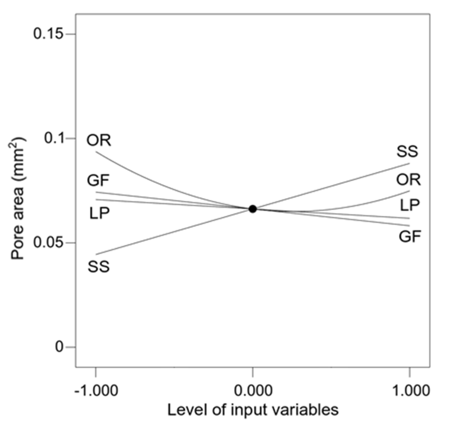
Figure 11 was obtained in a similar manner as Figure 7, which showed the influence of processing parameters on the pore area. During the laser cladding on the curved surface, the scanning speed, gas flow, and overlap rate showed a significant impact on the pore area, while the laser power had minor impact. A lower scanning speed was attributed to a smaller pore area. A negative correlation was observed between the increase of gas flow and pore area. The pore area showed an initial decrease and then an increase by increasing the overlap ratio.

3.4. Processing Parameters Optimization and Experimental Validation

The flatness ratio and pore area in the clad are the important factors in multi-track laser cladding property evaluation. According to the industrial needs, the optimization targets were set to maximize the flatness ratio and minimize the pore area. The limitations of the processing parameters were set to a range within the levels in Table 2. The importance factors for all the processing parameters were set to the default value of 3. The importance factors for the flatness ratio and pore area were set to the maximum value of 5. Then, optimization was conducted with Design-Expert software following the settings in Table 8.
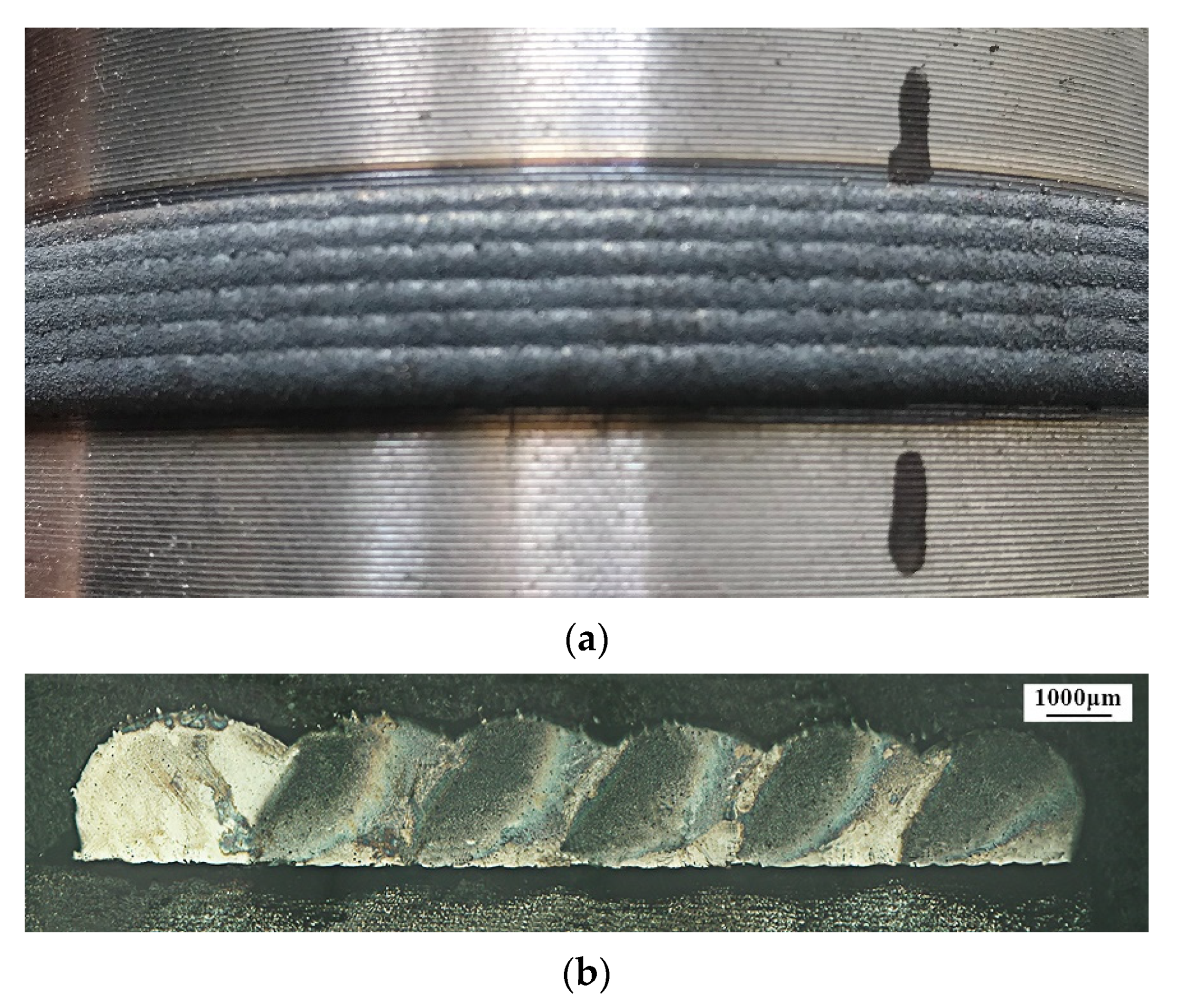
Table 9 below shows the optimized processing parameters set with the highest desirability based on the aforementioned target, which included 1499.998 W laser power, a 6 mm/s scanning speed, 1099.446 L/h gas flow, and 25.340% overlap ratio. To verify the effectiveness of this set of processing parameters, experimental validation was conducted by setting the processing parameters to 1500 W laser power, a 6 mm/s scanning speed, 1100 L/h gas flow, and 25.340% overlap ratio due to the equipment set point accuracy. Figure 12a showed the exterior appearance of the clad coated on the curved substrate. Figure 12b displayed the cross-section of the multi-track laser clad. Both the flatness and pore area of the clad were observed to show favorable cladding quality under this processing parameters set. The prediction of flatness ratio and pore area was calculated based on the models in Equations (3) and (4), which are also shown in Table 9. Compared with the actual measurement in the experimental validation, the error rates for the flatness ratio and pore area were 2.165% and 5.476%, respectively. Therefore, the prediction accuracy of the developed flatness ratio and pore area model were confirmed. Additionally, within the original 30 runs in Table 3, the smallest pore area occurred in the 11th run, which was 0.018 mm2. Meanwhile, the flatness ratio in the 11th run was 0.803049. Compared with the experimental validation results for the flatness ratio and pore area in Table 9, the optimized processing parameters brought a clad layer that had a pore area that was nearly at the same level as the best run in the original, while the flatness ratio increased by 5%. The best flatness ratio in the original 30 runs occurred in the 19th run, which was 0.918344. However, the corresponding pore area in the 19th run was 0.187 mm2. In the comparison with the optimized setup in Table 9, the pore area was improved to reduce more than 9 times. Since the optimization was conducted under the consideration of both flatness ratio and pore area with the same importance value, the optimization result exhibited promising results and application potential of the forming control on clad properties in a curved surface laser cladding.

4. Conclusions

Based on response surface methodology central composite design, this study established the mathematical model between processing parameters (laser power, scanning speed, gas flow, and overlap ratio) and clad properties (flatness ratio and pore area) in multi-track laser cladding on a curved surface. The models were verified by the diagnostic diagrams and experimental validation. The models provided the reference for processing parameters optimization, shaping the control and prediction of multi-track laser cladding on a curved surface. The following conclusions can be drawn from this study:
  • The flatness ratio of the cladding layer was significantly influenced by the overlap ratio. Under the relatively low laser power in the studied range, the flatness ratio slightly decreased with the reducing scanning speed. Under relatively high laser power in the studied range, the flatness ratio showed a significant increase upon reducing the scanning speed. Decreasing the laser power and overlap ratio simultaneously caused the flatness ratio to increase. Decreasing both the scanning speed and overlap ratio also lead to the flatness ratio increasing.
  • The scanning speed, gas flow, and overlap ratio had an influence on the pore area. With the increase of laser power and overlap ratio, the pore area was showing a trend of decreasing at first and then increasing afterwards. Increasing the gas flow and overlap ratio led the pore area to increase initially, which was followed by a decrease.
  • Processing parameters optimization was conducted comprehensively by considering maximizing the flatness ratio and minimizing the pore area in the clad. Through experimental validation, a different extent of improvement was found for the flatness ratio and pore area compared with the original CCD design. In addition, given the optimized processing parameters setup, the flatness ratio and pore area prediction were computed by the established mathematical models. Compared with the validation experiment values of the flatness ratio and pore area, predicting the adequacy of the models was verified and showed the application potential of the forming control of clad properties in curved surface laser cladding.

Author Contributions

Methodology, G.L. and Z.L.; experiment, Z.L.; analysis, G.L., Z.L., Y.Z., M.F., C.C. and J.J.; writing—original draft preparation, G.L. and Z.L.; writing—review and editing, G.L. and Y.Z.; supervision, G.L. and Y.Z. All authors have read and agreed to the published version of the manuscript.

Funding

This research was funded by the Fujian Provincial Education and Research Program for Young and Middle-Aged Teachers (Grant No. JAT190407).

Acknowledgments

The authors gratefully acknowledge the support from the Third Batch of Fujian Province Special Support on “Double Hundred Projects” Talents Program.

Conflicts of Interest

The authors declare no conflict of interest.

References

  1. Devojno, O.; Feldshtein, E.; Kardapolava, M.; Lutsko, N. On the formation features, microstructure and microhardness of single laser tracks formed by laser cladding of a NiCrBSi self-fluxing alloy. Opt. Lasers Eng. 2018, 106, 32–38. [Google Scholar] [CrossRef]
  2. Jiang, Y.; Li, J.; Juan, Y.; Lu, Z.; Jia, W. Evolution in microstructure and corrosion behavior of AlCoCrxFeNi high-entropy alloy coatings fabricated by laser cladding. J. Alloys Compd. 2019, 775, 1–14. [Google Scholar] [CrossRef]
  3. Sun, S.D.; Barr, C.; Brandt, M. In situ control of tempered martensite during laser cladding repair of aero-grade 300M steel using AISI 420 stainless steel powder. J. Laser Appl. 2018, 30, 032502. [Google Scholar]
  4. Liu, H.; Qin, X.; Huang, S.; Hu, Z.; Ni, M. Geometry modeling of single track cladding deposited by high power diode laser with rectangular beam spot. Opt. Lasers Eng. 2018, 100, 38–46. [Google Scholar] [CrossRef]
  5. Liu, J.; Yu, H.; Chen, C.; Weng, F.; Dai, J. Research and development status of laser cladding on magnesium alloys: A review. Opt. Lasers Eng. 2017, 93, 195–210. [Google Scholar] [CrossRef]
  6. Zeng, C.; Tian, W.; Liao, W.H.; Hua, L. Microstructure and porosity evaluation in laser-cladding deposited Ni-based coatings. Surf. Coat. Technol. 2016, 294, 122–130. [Google Scholar] [CrossRef]
  7. Nabhani, M.; Razavi, R.S.; Barekat, M. An empirical-statistical model for laser cladding of Ti-6Al-4V powder on Ti-6Al-4V substrate. Opt. Laser Technol. 2018, 100, 265–271. [Google Scholar] [CrossRef]
  8. Li, Y.; Dong, S.; Yan, S.; Liu, X.; He, P.; Xu, B. Microstructure evolution during laser cladding Fe-Cr alloy coatings on ductile cast iron. Opt. Laser Technol. 2018, 108, 255–264. [Google Scholar] [CrossRef]
  9. Erfanmanesh, M.; Abdollah-Pour, H.; Mohammadian-Semnani, H.; Shoja-Razavi, R. An empirical-statistical model for laser cladding of WC-12Co powder on AISI 321 stainless steel. Opt. Laser Technol. 2017, 97, 180–186. [Google Scholar] [CrossRef]
  10. Shi, J.; Zhu, P.; Fu, G.; Shi, S. Geometry characteristics modeling and process optimization in coaxial laser inside wire cladding. Opt. Laser Technol. 2018, 101, 341–348. [Google Scholar] [CrossRef]
  11. Ansari, M.; Razavi, R.S.; Barekat, M. An empirical-statistical model for coaxial laser cladding of NiCrAlY powder on Inconel 738 superalloy. Opt. Laser Technol. 2016, 86, 136–144. [Google Scholar] [CrossRef]
  12. Farahmand, P.; Kovacevic, R. Parametric study and multi-criteria optimization in laser cladding by a high power direct diode laser. Lasers Manuf. Mater. Process. 2014, 1, 1–20. [Google Scholar] [CrossRef]
  13. Saqib, S.; Urbanic, R.; Aggarwal, K. Analysis of laser cladding bead morphology for developing additive manufacturing travel paths. Procedia CIRP 2014, 17, 824–829. [Google Scholar] [CrossRef] [Green Version]
  14. Calleja, A.; Tabernero, I.; Fernández, A.; Celaya, A.; Lamikiz, A.; De Lacalle, L.L. Improvement of strategies and parameters for multi-axis laser cladding operations. Opt. Lasers Eng. 2014, 56, 113–120. [Google Scholar] [CrossRef]
  15. Tabernero, I.; Calleja, A.; Lamikiz, A.; De Lacalle, L.L. Optimal parameters for 5-axis laser cladding. Procedia Eng. 2013, 63, 45–52. [Google Scholar] [CrossRef] [Green Version]
  16. Lian, G.; Yao, M.; Zhang, Y.; Chen, C. Analysis and prediction on geometric characteristics of multi-track overlapping laser cladding. Int. J. Adv. Manuf. Technol. 2018, 97, 2397–2407. [Google Scholar] [CrossRef]
  17. El Cheikh, H.; Courant, B.; Branchu, S.; Hascoet, J.Y.; Guillén, R. Analysis and prediction of single laser tracks geometrical characteristics in coaxial laser cladding process. Opt. Lasers Eng. 2012, 50, 413–422. [Google Scholar] [CrossRef] [Green Version]
  18. Liu, S.; Kovacevic, R. Statistical analysis and optimization of processing parameters in high-power direct diode laser cladding. Int. J. Adv. Manuf. Technol. 2014, 74, 867–878. [Google Scholar] [CrossRef]
  19. Chen, C.; Lian, G.; Jiang, J.; Wang, Q. Simplification and experimental investigation of geometrical surface smoothness model for multi-track laser cladding processes. J. Manuf. Process. 2018, 36, 621–628. [Google Scholar] [CrossRef]
  20. Wen, P.; Feng, Z.; Zheng, S. Formation quality optimization of laser hot wire cladding for repairing martensite precipitation hardening stainless steel. Opt. Laser Technol. 2015, 65, 180–188. [Google Scholar] [CrossRef]
  21. Lian, G.; Zhang, H.; Zhang, Y.; Tanaka, M.L.; Chen, C.; Jiang, J. Optimizing processing parameters for multi-track laser cladding utilizing multi-response Grey relational analysis. Coatings 2019, 9, 356. [Google Scholar] [CrossRef] [Green Version]
  22. Lian, G.; Zhang, H.; Zhang, Y.; Chen, C.; Huang, X.; Jiang, J. Control and prediction of forming quality in curved surface multi-track laser cladding with curve paths. Int. J. Adv. Manuf. Technol. 2020, 106, 3669–3682. [Google Scholar] [CrossRef]
  23. Alam, M.K.; Urbanic, R.J.; Nazemi, N.; Edrisy, A. Predictive modeling and the effect of process parameters on the hardness and bead characteristics for laser-cladded stainless steel. Int. J. Adv. Manuf. Technol. 2018, 94, 397–413. [Google Scholar] [CrossRef]
  24. Zhou, C.; Zhao, S.; Wang, Y.; Liu, F.; Gao, W.; Lin, X. Mitigation of pores generation at overlapping zone during laser cladding. J. Mater. Process. Technol. 2015, 216, 369–374. [Google Scholar] [CrossRef]
  25. Zhou, S.; Dai, X.; Zheng, H. Microstructure and wear resistance of Fe-based WC coating by multi-track overlapping laser induction hybrid rapid cladding. Opt. Laser Technol. 2012, 44, 190–197. [Google Scholar] [CrossRef]
Figure 1. Laser cladding system (a) schematic illustration; (b) photo of experimental equipment.
Metals 10 01109 g001aMetals 10 01109 g001b
Figure 2. (a) Schematic illustration of laser cladding tracks on a round rod; (b) schematic illustration of a linear cutting location to obtain the cross-section of the cladding layer; (c) schematic illustration of the cladding layer’s cross-section to be investigated; (d) example microstructure in the cross-section of the clad coated on the substrate.
Metals 10 01109 g002
Figure 3. (a) Residual plot of flatness ratio; (b) Comparison of predicted and actual flatness ratio.
Metals 10 01109 g003
Figure 4. (a) Response surface of laser power and scanning speed interaction affecting the flatness ratio; (b) Contour line of the response surface.
Metals 10 01109 g004
Figure 5. (a) Response surface of laser power and overlap ratio interaction affecting the flatness ratio; (b) Contour line of the response surface.
Metals 10 01109 g005
Figure 6. (a) Response surface of scanning speed and overlap ratio interaction affecting the flatness ratio; (b) Contour line of the response surface.
Metals 10 01109 g006
Figure 7. The influence of different processing parameters on the flatness ratio.
Metals 10 01109 g007
Figure 8. (a) Residual plot of the pore area; (b) Comparison of predicted and actual pore area.
Metals 10 01109 g008
Figure 9. (a) Response surface of laser power and overlap ratio interaction affecting the pore area; (b) Contour line of the response surface.
Metals 10 01109 g009
Figure 10. (a) Response surface of gas flow and overlap ratio interaction affecting the pore area; (b) Contour line of the response surface.
Metals 10 01109 g010
Figure 11. The influence of different processing parameters on the pore area.
Metals 10 01109 g011
Figure 12. (a) Exterior appearance of laser clad coated on the substrate; (b) Cross-section of multi-track clad.
Metals 10 01109 g012
Table 1. Elemental composition (wt%) of W6Mo5Cr4V2 high-speed steel powder.
CSiMnCrMoVWFe
0.8–0.90.15–0.40.2–0.453.8–4.44.5–5.51.75–2.25.5–6.75Rest
Table 2. Laser cladding processing parameters in central composite design.
Input VariablesNotationUnitLevels
–2–1012
Laser PowerLPW12001300140015001600
Scanning SpeedSSmm/s56789
Gas FlowGFL/h800900100011001200
Overlap RatioOR%1020304050
Table 3. Central composite design of input variables and the corresponding responses.
RunLP (W)SS (mm/s)GF (L/h)OR (%)Flatness RatioPore Area (mm2)
114007.001000.0050.000.7839460.118
213008.001100.0020.000.9087870.116
315006.001100.0020.000.8638920.029
414007.001000.0030.000.8432600.054
515006.001100.0040.000.8652080.079
614005.001000.0030.000.8522680.036
714007.001000.0030.000.8493500.071
813008.001100.0040.000.7981560.083
915008.00900.0020.000.8387930.119
1014009.001000.0030.000.8206940.102
1113006.00900.0040.000.8030490.018
1214007.001000.0030.000.8440270.048
1315006.00900.0020.000.8505770.067
1413008.00900.0040.000.8088280.085
1514007.001000.0030.000.8415140.055
1614007.001000.0030.000.8511790.066
1715008.001100.0040.000.7953170.147
1812007.001000.0030.000.8226370.085
1913008.00900.0020.000.9183440.187
2015006.00900.0040.000.8780690.071
2114007.001200.0030.000.8356420.035
2213006.00900.0020.000.8681770.108
2315008.00900.0040.000.7976780.098
2413006.001100.0040.000.7855710.034
2514007.00800.0030.000.8448170.078
2613006.001100.0020.000.8526080.097
2714007.001000.0010.000.8801140.147
2815008.001100.0020.000.8273430.060
2914007.001000.0030.000.8412090.069
3016007.001000.0030.000.8466990.060
Table 4. Significance test for different flatness ratio model options.
SourceSequential p-ValueLack of Fit p-ValueComments
Linear0.00140.0002-
2-Factor Interaction<0.00010.0647Suggested
Quadratic0.45380.0570-
Cubic0.30410.0396-
Table 5. Significance test for different pore area model options.
SourceSequential p-ValueLack of Fit p-ValueComments
Linear0.01940.0034-
2-Factor Interaction0.01330.0099-
Quadratic<0.00010.1682Suggested
Cubic0.08340.4882-
Table 6. Analysis of variance on flatness ratio.
SourceSum of SquaresDegrees of FreedomMean SquareF Valuep-Value
Prob > F
Comments
Model0.03074.325 × 10−378.53<0.0001significant
LP1.923 × 10−511.923 × 10−50.350.5606-
SS7.827 × 10−417.827 × 10−414.210.0011-
GF3.009 × 10−413.009 × 10−45.460.0289-
OR0.01410.014262.45<0.0001-
LP × SS6.534 × 10−316.534 × 10−3118.63<0.0001-
LP × OR5.928 × 10−315.928 × 10−3107.64<0.0001-
SS × OR2.255 × 10−312.255 × 10−340.94<0.0001-
Residual1.212 × 10−3225.507 × 10−5---
Lack of Fit1.124 × 10−3176.612 × 10−53.780.0739not significant
R-Squared0.9615Pred R-Squared0.9260
Adj R-Square0.9493Adeq Precision32.267
Table 7. Analysis of variance on pore area.
SourceSum of SquaresDegrees of FreedomMean SquareF Valuep-Value
Prob > F
Comments
Model0.03975.618 × 10−334.51<0.0001significant
LP4.851 × 10−414.851 × 10−42.980.0983-
SS0.01110.01170.30<0.0001-
GF1.557 × 10−311.557 × 10−39.560.0053-
OR2.126 × 10−312.126×10−313.060.0015-
LP × OR0.01010.01063.88<0.0001-
GF × OR3.903 × 10−313.903 × 10−323.98<0.0001-
OR29.411 × 10−319.411 × 10−357.81<0.0001-
Residual3.582 × 10−3221.628 × 10−4---
Lack of Fit3.140 × 10−3171.847 × 10−42.090.2123not significant
R-Squared0.9165Pred R-Squared0.8325
Adj R-Square0.8900Adeq Precision22.918
Table 8. Optimization criteria and targets.
Input and OutputUnitCriterionLimitImportance
LowerUpper
Processing ParametersLaser PowerWIn range120016003
Scanning Speedmm/sIn range593
Gas FlowL/hIn range80012003
Overlap Ratio%In range10503
ResponsesFlatness Ratio-Maximum0.78390.91835
Pore Areamm2Minimum0.0180.1875
Table 9. Processing parameters optimization, responses comparison between predicted and experimental validation.
ComparisonLPSSGFORFlatness RatioPore AreaDesirabilityNotes
Optimization and prediction1499.99861099.44625.3400.8610.0210.749Selected
Experimental Validation15006110025.3400.843260.01985--