Review

Spark Plasma Sintering of Titanium Aluminides: A Progress Review on Processing, Structure-Property Relations, Alloy Development and Challenges

by
Ntebogeng F. Mogale
* and
Wallace R. Matizamhuka
Department of Metallurgical Engineering, Vaal University of Technology, Vanderbijlpark 1911, South Africa
*
Author to whom correspondence should be addressed.
Metals 2020, 10(8), 1080; https://doi.org/10.3390/met10081080
Submission received: 1 May 2020 / Revised: 2 June 2020 / Accepted: 5 June 2020 / Published: 11 August 2020

Abstract

:
Titanium aluminides (TiAl) have the potential of substituting nickel-based superalloys (NBSAs) in the aerospace industries owing to their lightweight, good mechanical and oxidation properties. Functional simplicity, control of sintering parameters, exceptional sintering speeds, high reproducibility, consistency and safety are the main benefits of spark plasma sintering (SPS) over conventional methods. Though TiAl exhibit excellent high temperature properties, SPS has been employed to improve on the poor ductility at room temperature. Powder metallurgical processing techniques used to promote the formation of refined, homogeneous and contaminant-free structures, favouring improvements in ductility and other properties are discussed. This article further reviews published work on phase constituents, microstructures, alloy developments and mechanical properties of TiAl alloys produced by SPS. Finally, an overview of challenges in as far as the implementation of TiAl in industries of interest are highlighted.

1. Introduction

Titanium-based intermetallics can be defined as metallic materials consisting of approximate stochiometric ratios in ordered crystal structures [1]. These have properties such as low densities and high melting points, good high-temperature strength, resistance to oxidation and creep [2]. The research interest in intermetallics for at least the past 30 years according to Muktinutalapati & Nageswara [3] has been due to the need to replace the previously used NBSAs (8–8.5 g/cm3 in density) with lower density (4–7 g/cm3) materials, saving about 55% of the weight gain of turbine engines [4].
Much attention was given to titanium (Ti) and nickel-based aluminides amongst many others. Of interest for this research work is titanium aluminides (TiAl). According to Muktinutalapati and Nageswara, intermetallics around TiAl can be classified into two-alpha (α2)-Ti3Al and gamma (γ)-TiAl phase. The greatest disadvantage of α2-Ti3Al is poor toughness and fatigue crack growth, shifting much research and development more on γ-TiAl. These possess properties which include good creep and oxidation properties at elevated temperature applications, low densities (3.9–4.2 g/cm³ varying with composition), high stiffness and yield strength [5].
It has been over 20 years since the successful implementation of gamma titanium aluminide (γ-TiAl) alloys in aerospace components produced by companies such as General Electric Aircraft Engines, Pratt and Whitney and Rolls Royce [6,7,8]. The alloys have been employed in various aerospace components such as rotating and static engine components used in turbines, compressors, combustors, and nozzles. Research development of such alloys over the years primarily focused on the refinement of microstructure and improvement of properties, particularly ductility and formability, through compositional optimisations and application of various processing technologies.
Compositional variations including controlling gaseous impurities such as oxygen (O) and nitrogen (N), and the addition of chromium (Cr) and manganese (Mn) to TiAl alloys have been previously addressed with the aim of ductility improvement [9,10,11]. Furthermore, employing wrought processing techniques followed by post-treatments have also been extensively experimented [12,13,14]. However, microstructural inconsistencies resulting from solidification and phase transformations further deteriorate and scatter the mechanical properties of the alloys [15,16]. Spark plasma sintering (SPS) presents an opportunity to consolidate metallic powder materials without the deviations mentioned above. The process employs DC pulses of high intensity and pressure to achieve the required sintering temperature under a specified time. The SPS technique has been used in a large number of investigations and has advantages compared to traditional techniques such as shorter holding times, lower sintering temperatures and marked increases on the properties of materials [17,18,19]. This work is a summary of the progress, advances and challenges in the production and implementation of spark plasma sintered γ-TiAl alloys.

2. Powder Metallurgical Processing of γ-TiAl Alloys

2.1. Gas Atomization (GA)

The current preferred method for mass production of metallic powders consolidated using various methods including SPS is GA [20,21]. Although GA is said [21] to be more costly compared to water atomization, improved yields of spherical powders are achieved aiding flowability. The conventional basic operation of gas atomisation (GA) is illustrated in Figure 1. During GA, the metal or alloy is melted inside a crucible, followed by pouring the stream of hot metal liquid and finally pulverizing using a pressurized gas jet. The solidified metal droplets are then accumulated at the powder container for collection. According to Martín et al. [21], processing parameters such as the melt temperature and flow, nozzle type and gas purity and pressure affect the powder size and quality.
The production of γ-TiAl powders using GA is rather challenging. This can be ascribed to the high reactivity of the melt with the crucible lining material and the high impurity gas pick-up of the melt, atomized droplets and the hot powder particles [23]. As a result, cold-crucible or crucible-free techniques such as electrode induction melting gas atomization (EIGA) and plasma melting induction guiding gas atomization (PIGA) can be employed. For further reading on these techniques, the reader is referred to [24,25,26].
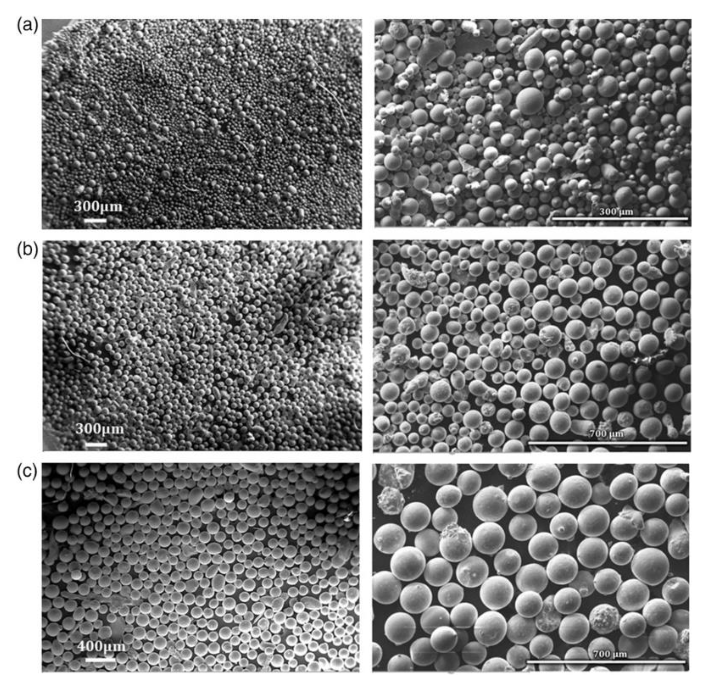
Powder characteristics of concern during the GA production of γ-TiAl affecting powder quality are particle size distributions, gaseous impurity levels and cooling rates [23]. The morphology of powders produced using GA, as shown in Figure 2, is spherical despite the particle size. Spherical powders are beneficial to subsequent PM processes, promoting flowability and packing density. The level of impurity gases such as O and N in GA produced powders can impair the mechanical properties after consolidation. Furthermore, oxide or nitride layers on powder surfaces may hinder compaction [23]. Minimal gas entrapment can be achieved by using an inert gas atmosphere during powder alloy atomization and handling. Finally, GA employs high cooling rates enhancing microstructural and compositional uniformity.
Several studies involving the use of GA and SPS have been carried out to date [27,28,29,30]. Gu et al. [27] fabricated pre-alloyed (PA) Ti–43Al–5Nb–2V–Y (at. %) powders utilizing the PIGA technique and densified the powders at different temperatures by SPS. The morphology of the varying particle size (50–120 μm) PA powders was reported as spherical with satellite particles. Moreover, a cellular dendritic interior microstructure was observed, a characteristic microstructure of rapidly solidified metal droplets. In a related study, Liu and associates [28] studied the size-dependency on structural properties of a Ti–48Al–2Cr–8Nb (at. %) powder alloy produced using EIGA for PM and additive manufacturing technologies. It was found that decreasing the powder particle size decreased the content of the γ and increased that of α2-phase.

2.2. Mechanical Milling (MM)

PA powder can be effectively manufactured using MM [31]. As stated by Xiao et al., MM aids solid diffusion and rapid compound formation. In work done by Hadef [32]; it is stated that milling includes grinding through impact, compression and attrition. During MM experiments, powders are introduced in required proportions into hardened steel (typically tungsten carbide, stainless steel and zirconia) vial along with milling balls of a selected size. Voluntarily, a process control agent (PCA) is also added to aid in minimising cold welding and lump formation. Collisions between the wall of the vial and the contents thereof exist at high frequencies and velocities, effectively milling the powder contained [33]. Milling time and speed, vial type, milling media, ball-to-powder weight ratio (BPR), milling atmosphere and the level of vial filling are parameters affecting the ultimate powder mix constituents.
Extensive research has been devoted over the years to study the effect of the various milling parameters on the constitution of the ultimate powder mix [34,35]. Oehring et al. [36], investigated the milling process of elemental Ti–Al powder blends using detailed X-ray diffraction (XRD) analysis and found that a dual mixture of hcp solid solution and an amorphous phase in alloy Ti50Al50 exist at lower milling intensities. Oehring et al. also found that energetic destabilisation of present phases occurring during milling results in the final observed intermetallic compounds. Zhang et al. [37] studied phase formation during milling of Ti–75Al powder mixtures using XRD analysis and concluded that a solid solution of Al(Ti) formed as a result diffusion of Ti into Al during the early milling stages. In addition to the study findings, an L12 ordered Al3Ti phase with an average phase grain size of 18 nm was formed with extended milling time.
Wang et al. [38] studied the effects of SPS temperature and mechanical milling treatment parameters on the phase constitution and microstructure. The as-atomised powder following SPS at 1200 °C showed microstructural inhomogeneities consisting of α2 and γ and some lamella colonies as compared to the homogeneous, fully dense MM powder. Additionally, it was found that extended milling times and speeds during MM attribute to the uniform distribution of the phases present.
Double mechanical milling (DMM) has recently gained attention [39,40] and involves two milling stages. The initial stage normally entails mixing of the elemental powders at low speeds, followed by high-energy ball milling at higher speeds for a shorter interval. Optionally, the powder mix is removed from the vial and heat-treated in a controlled atmosphere before the final milling stage at higher speeds and longer intervals. In a study employing DMM on TiAl alloys [40], the authors reported the formation of a regular shaped powder with a particle size decrease from a maximum of 80 to 40 µm after the final milling stage. Consequently, peak broadening was observed and can be attributed to the reactions and interdiffusion occurring between phases. In a similar study Shulong et al. [39] obtained an ultrafine regular powder morphology after DMM with sizes in the range of 20–40 μm.

2.3. Mechanical Alloying (MA)

The process of mechanical alloying (MA) involves loading of PA or elemental powders inside a high energy ball mill and the usage of grinding media to repeatedly cold weld, fracture and reweld powder particles [41]. Parameters including time, speed and BPR [42] are optimised to control and balance the resultant powder particle sizes. PCA are inorganic compounds [43] often used in MA of ductile metals to prevent agglomeration of powder particles. According to Suryanarayana [41], adding 1–2 wt. % of PCA can prevent excessive cold welding or agglomeration of the individual powders on the grinding media and the milling vessel. The working principles of MA involve the excessive deformation of powder particles through work hardening and flattening of colliding or contacting ductile particles using grinding media. In addition, intermetallic compounds are refined and fractured, while oxide dispersoids comminuted.
MA has proven to be effective in the production of non-equilibrium and nanostructured TiAl alloys [44,45,46]. Some of the successful developments in TiAl research through MA include the ability to produce fine-grained alloys [47], although some shortcomings, such as gas contamination [48] still need to be overcome. Sim et al. [46] found that alloys sintered from a 40 h MA powder showed promising yielding and ultimate strength in compression. The reported yielding and ultimate strength values from the previous study were as high as 1644 and 2542 MPa, respectively. Failure strains at both ambient temperatures and 650 °C were 31.3% and 55.3%. Forouzanmehr and colleagues [45] found that the milling of Ti–50Al (at. %) powder mixture formed a Ti(Al) solid solution earlier in milling, followed by a transformation of the amorphous structure to a Ti(Al) that is supersaturated with longer milling durations. Additionally, further annealing treatment for the amorphous and the supersaturated Ti(Al), formed a nanocrystalline TiAl intermetallic compound with an ultrafine grain size of ~50 nm and a microhardness value of ~11.67 GPa.
To limit elevated temperature grain growth in γ-TiAl and other PA powders, Bohn et al. [47] found that the addition of Si to Ti powders (resulting in precipitates of Ti5(Si,Al)3 embedding on grain boundaries of γ-TiAl matrix) gave refined microstructures with a grain size ranging from 160–480 nm for the matrix and 80–190 nm for the precipitates. To produce low contaminated TiAl powder, Bhattacharya et al. [48] found planetary ball billing to have to increase O contents. At the same time, insignificant impurity levels (O pick-up of ≈ 0.014 wt. % and N pick-up of 0.031 wt. %) were observed in attrition milled powders. However, in both cases, the powders used were handled in a glovebox with purified Ar atmosphere.

2.4. Cryomilling (CM)

Another interesting PM technique that evolved as a modification of the conventional high energy ball milling is cryomilling (CM). The process involves soaking grinding media in a cryogenic liquid (such as N) while optimising processing parameters to minimise recovery and recrystallisation, resulting in ultra-refined grain structures [49]. According to Lavernia et al., benefits of employing CM over traditional milling include the reduction of cold welding and powder agglomeration to the grinding media producing effective milling outcomes, limited powder oxidation occurrences and reduced milling times. Consolidation is required after CM processing, allowing the exploration of studies on phase and microstructural evolutions as a function of properties, comparable to those produced using conventional ball milling.
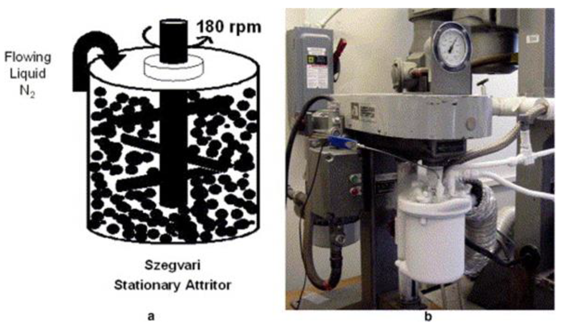
Figure 3 shows the basic setup used for CM. The apparatus involves thermocouples used to monitor the mill and ensure a constant cryogenic liquid level, thus maintaining a constant milling environment [50]. Additionally, the cryogenic liquid is in constant circulation into the mill with excess liquid drained through a particle filtering blower, enabling powder particle entrainment in the gas flow. Compatibly, the setup comprises of opening and closing valves to ease the flow of the cryogenic liquid and are monitored by temperature fluctuations above the slurry level. Some of the implemented configurations, according to Witkin & Lavernia, are 101 attritor mills used at the University of California in Davis, charging up to 1 kg of powder and the commercialised 35 kg capacity attritor mill sponsored by" Boeing’s Rocketdyne division.
Several recent studies [51,52,53,54] have been devoted to understanding the processing and behaviour of nanostructured TiAl alloys produced using CM and SPS. Shanmugasundaram et al. [52], investigated the densification and microstructure of a γ-TiAl alloy produced using gas atomised CM powder and consolidated using SPS at 1050 and 1200 °C. CM resulted in a 100% powder yield, reduced particle (2–50 μm) and crystalline sizes (40 nm). Although the alloy fully densified at 1200 °C, 8 h of CM resulted in a decrease in the sintering temperature. The obtained refined microstructure (with grain sizes of 0.9 and 0.6 μm at 1200 and 1050 °C) consisted of γ and α2, with volume fraction of the later found to be dependent on the sintering temperature and O content. Deng et al. [51] obtained an ultrafine-grained FL and near γ microstructure promoted by CM and varying sintering temperatures of 900, 1000 and 1100 °C, respectively. The authors found that sintering at 1000 °C produced excellent compression properties, with yield strengths as high as 1575 MPa RT and 955 MPa at 850 °C.

3. Powder Consolidation by SPS

3.1. Basic Operating Principles

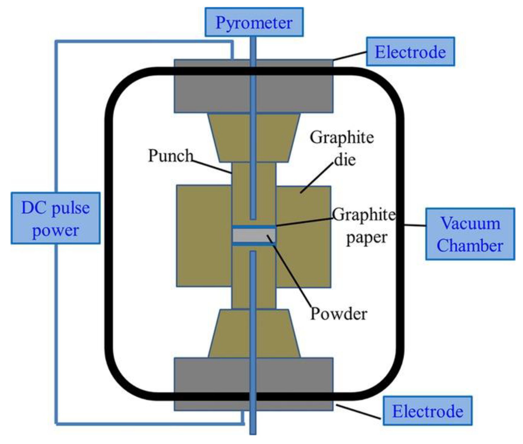
SPS, also referred to as field assisted sintering technique is a powder metallurgy (PM) method used to consolidate powders subjected to applied current and pressure [17]. As stated by Munir et al., the practice (schematically shown in Figure 4) employs uniaxial pressure and pulsed high direct current to consolidate powders. The science behind the successful consolidation of the powders is attributed to the sufficient generation of Joule heating [55], employing voltages below 10V and currents as high as 10 kA in conjunction with the electrically conductive tool materials used in the set-up. The widely used SPS technique has advantages compared to conventional manufacturing techniques such as hot-pressing, pressureless sintering, laser sintering and hot isostatic pressing (HIP). These advantages include shorter holding times, lower sintering temperatures and marked increases in the properties of materials [18,19,56].

3.2. Mechanisms of Sintering in SPS

The complex mechanisms and theories involved in SPS are as a result of electrical, thermal and mechanical effects [55]. Of the vast available models and theories, the standard and accepted involves effects due to joule heating, plasma generation and electroplasticity [58,59]. According to Matizamhuka [58], the electrical effects are related to the electrical properties of the powders. Furthermore, electrically conductive powders allow smooth current flow and are heated by the "Joule effect" and transferred to the bulk of the powder by conduction. The formation of necks between the powder particles through cleaning of powder surfaces, welding and vaporization is enhanced by the electric current flow through particles when pressure is applied [60]. Additionally, the electric current pulses produced during SPS are said to accelerate the densification kinetics existing between powder particle necks. The formation of arcs and plasma between powder particles promotes localized melting in amorphous material jet-form between spherical nanosized ceramic particles [61], through liquid wetting [62] and partial melting in W and ZrB2 ceramic particles [63].
The mechanical effects promoting densification are related to the quasi-static compressive stress applied in SPS [55]. This results in better particle contact, altering the morphology and amount of contacting particles and further enhancing the existing densification kinetics related to viscous flow, lattice, and grain boundary diffusion. Alternatively, new mechanisms like grain boundary sliding or deformation plastically can be activated [64]. The most common thermal factor promoting densification during SPS is the heating rate. In the study conducted by Olevsky and colleagues [65], high heating rates reduced noncontributing surface diffusion, favoring sinterability and intensifying densification by grain boundary diffusion. Furthermore, high rates of heating were found to retard grain growth.

3.3. SPS Modeling for Complex-Net Shaping

Advanced nanomaterials can potentially be manufactured using SPS owing to the impressive characteristics offered by the process. These include pressures as high as 100 MPa, temperatures of up to 2500 °C, heating rates ranging up to 1000 K.min−1 and pulsed electric current readings of a few thousand amperes [66]. Despite these benefits, the challenge of manufacturing complex shapes beyond the traditional 2-D parts remains. This is due to the homogeneity variations experienced during the densification of components having high thickness regions, wherein the thicker regions require more shrinkage compared to the rest of the component [66,67]. To date, various models have been employed in SPS to overcome those, as mentioned earlier. These include modified punch designs [68], controlling punch displacement through the usage of sacrificial materials [69], deformed interface approach [70], finite element method (FEM) [67,71], and the controllable interface approach [66].
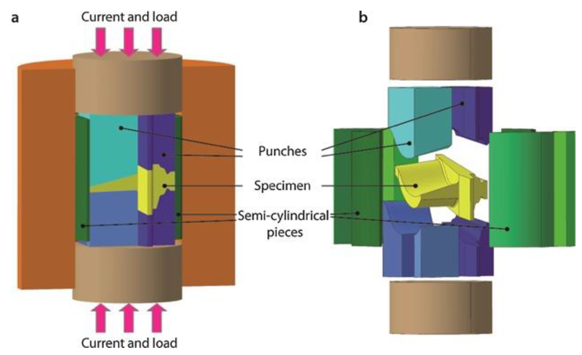
Voisin et al. [68], produced two GA γ-TiAl alloys to the nominal composition of Ti49.92Al48W2B0.08 and Ti48Al48Cr2Nb2 using SPS. Difficulty was experienced in as far as shaping a blade with a thick root and a thin foil, raising the need to design a mold of graphite (in Figure 5) consisting of a multiple punch assembly, the matrix and cylindrical pieces. The FEM was later employed to control the temperature at each point in the sample [72]. An 80 mm long blade was obtained by employing models in Figure 5 and FEM. The FEM was proven [71] to be reliable for qualitative predictions of powder sample grain growth and densification kinetics in SPS with a given temperature regime.
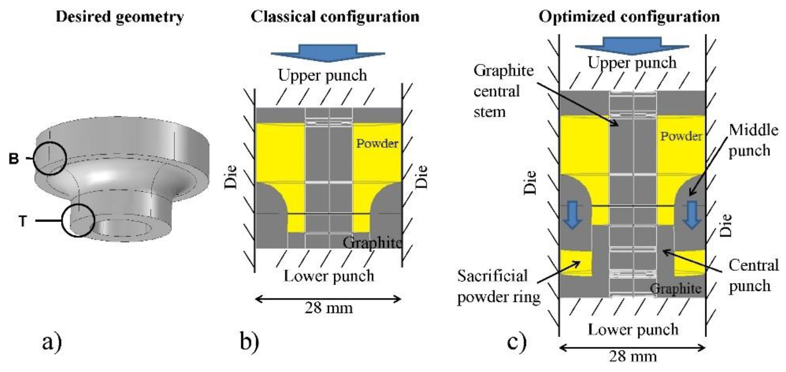
Alternatively, a sacrificial material (such as in Figure 6) can be used to achieve complex part homogeneity. According to Manière and colleagues [69], this approach presents advantages such as possibilities of fully densifying parts of varying thickness complexities, even stress distributions as a result of shrinkage uniformity at all points on the sample and control over the final part shape. Unfortunately, this approach has shortcomings related to material losses of the sacrificial component and the limitations of the number of thickness variations.
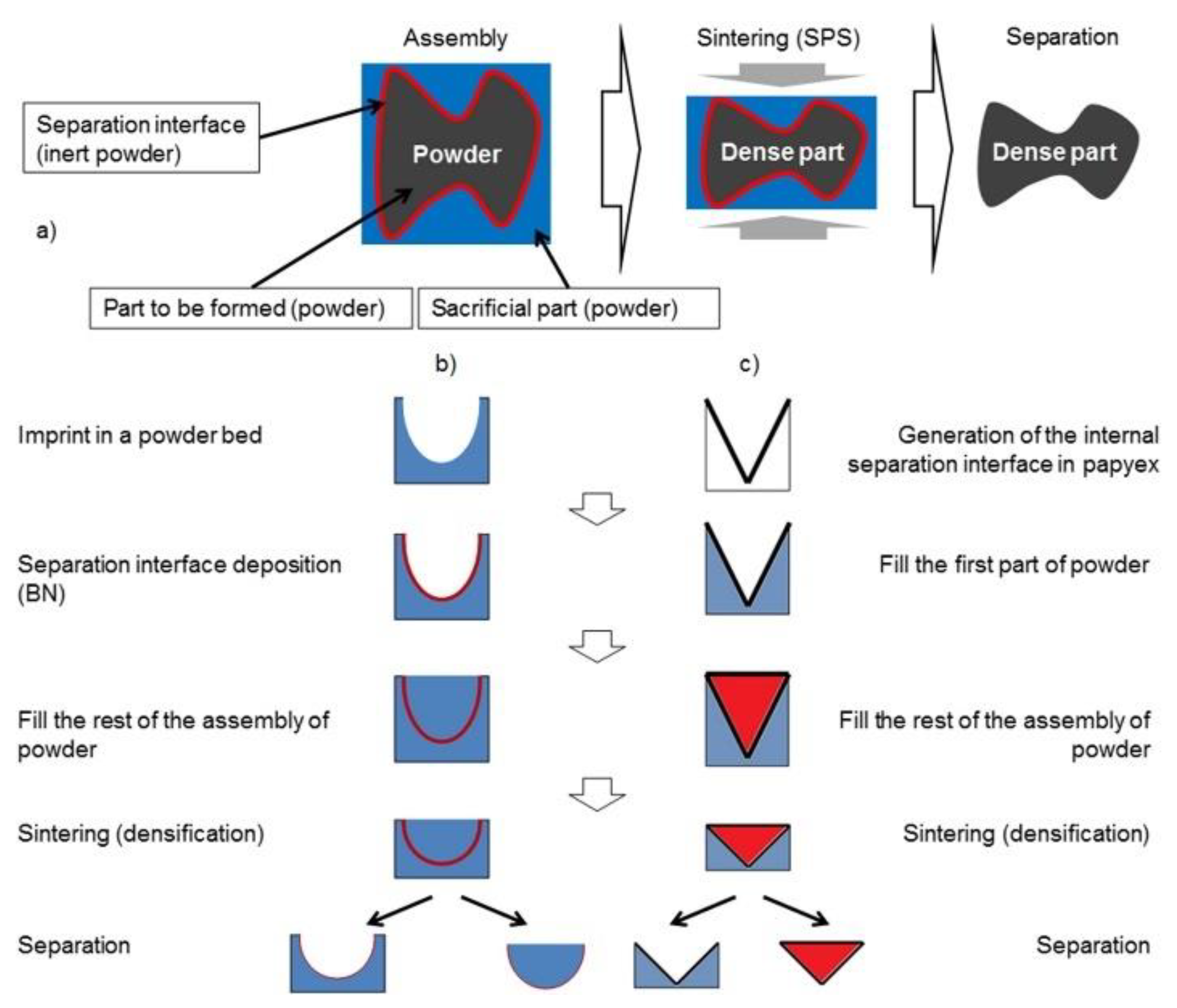
Commonly known as the "DEFORMINT" approach, the deformed interfaces method involves assembling a minimum of two porous materials (i.e., porous bodies or powder beds) separated by single or multiple interfaces [70]. Manière et al. described that the simple geometry on the outside (i.e., often cylindrical) is obtained by assembling a porous complex shape that is covered by a separation material and surrounded by an additional porous sacrificial material, that is the reverse of the initial shape. The detailed process steps for the deformed interfaces method are shown in Figure 7, and consists of the reproduction of porous assembly materials, densification of the assembly materials and sacrificial parts removal. Successful implementation of this method includes a 98% densification of a highly complex CoNiCrAlY alloy turbine blade developed by Manière et al. [70].
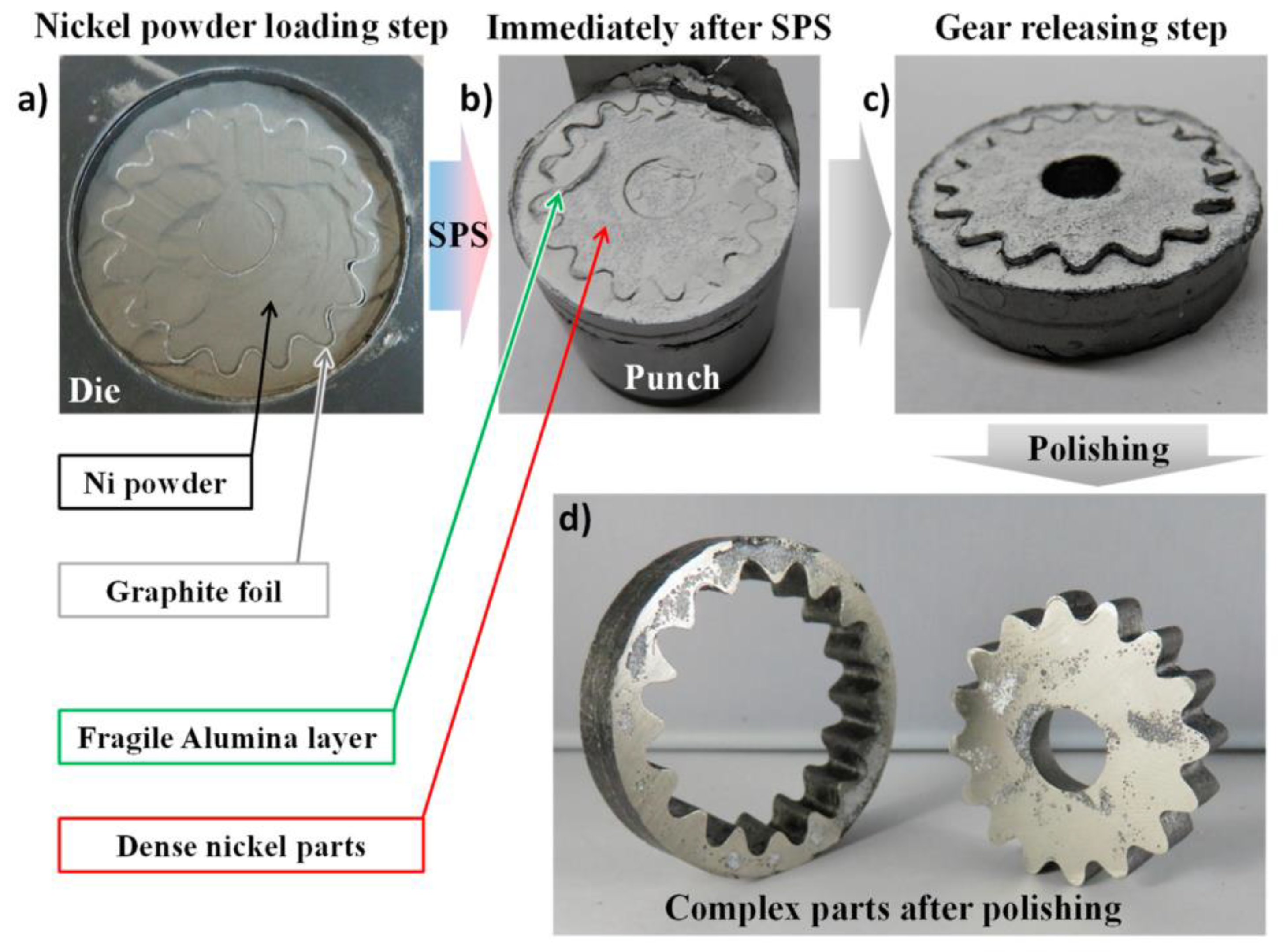
Finally, the recent controllable interface approach combines the adjustable interface thermal/electrical fluxes and the DEFORMINT approach. The controllable interface approach has been successfully used to manufacture 40 mm nickel gears [66], and the process steps (in Figure 8) for this consisted of powder loading into the assembly, SPS densification, removal of densified gear and polishing. SPS is modified by this approach through multiple die tooling, improving on the production number of complex shapes.

3.4. Carburation at High Temperature during SPS

One of the major challenges during the processing of materials using SPS is carbon (C) contamination experienced at high temperatures, also known as carburation. For this reason, caution should be taken when selecting tooling materials. Pressing tools are generally covered with graphite foils/sheets to ease sample removal subsequent to SPS [73,74]. Therefore, at temperatures above 600 °C, reactions between the graphite covered tools and the O present in the sample may occur. Excess O, as stated by Franceschin et al. [73], can arise from the gaseous sintering atmosphere or moisture. The vigorous gaseous transportation occurring between the sample and the graphite mold may encourage the precipitation of C or carbides [55].
The effects of carburation on SPS manufactured materials are numerous. Waseem et al. [75] characterized a TixWTaVCr alloy synthesized using SPS and detected up to 0.83 wt. % of C during gas fusion analysis. The presence of C was ascribed to the diffusion of graphite into the samples during SPS. Furthermore, the presence of a TiC phase was observed during XRD analysis resulting in a ~30 µm thick layer on the surface of the samples. Moreover, the availability of TiC may be beneficial, improving on the resistance to irradiation and high heat fluxes. Meir et al. [76] showed that during the SPS densification of a magnesia–aluminate spinel, carbide precipitation was enhanced by the C containing atmosphere from the SPS apparatus. Carbide precipitation was found to impair light transmittance and even opacity in LiF-free samples. Additionally, volatile (CF)n species were formed at high temperatures due to the interaction between C and LiF vapor.
Of much interest to this paper is carburation in TiAl alloys manufactured using SPS. Martin et al. [77] fully densified a commercial 48-2-2 TiAl powder by SPS and developed a two-fold protocol to obtain the desired microstructure and avoid TiC formation. Firstly, 8 and 10 mm samples were densified at 1200 °C below 50 MPa to obtain fully densified compacts with minimal (less than 1 µm) growth of the TiC layer. Secondly, the sample was introduced into a 36 mm inner diameter graphite mold, avoiding any contact between the sample and mold walls. Lastly, an annealing treatment for 5 min at 1360 °C was carried out with minimal load application to promote current conduction. TiC layer formation was achieved through avoiding mutual contact between the mold walls and the sample.
To avoid carburation, graphite pressing tools can be reinforced with C fibers to improve on the mechanical strength [78]. Additionally, double-walled tools with inner ceramic die and an outer graphite covering may be employed. Tooling material made from refractories and steel such as silica, alumina, concrete, TNZ molybdenum and copper-beryllium alloys may be such employed at sintering temperatures below 1000 °C [79,80]. Finally, the graphite tools can be separated from the sample by using foil layers such as hexagonal boron nitride [81] or alumina [82].

4. Crystallographic Phases and Microstructures

4.1. Crystallographic Phases

The characteristic phases existing in SPS produced γ-TiAl alloys are TiAl (γ), Ti3Al (α2) or dual (γ + α2). The γ-phase has an L10 type face-centred tetragonal structure [83] consisting of atomic layers at 90° to the c-axis [84] with lattice parameters a = 0.4005 nm, c = 0.4070 nm and a tetragonality ratio (c/a) of 1.02 [85,86]. Two peritectic reactions exist near the equiatomic composition [87]:
L + βα and L + αγ.
The prime phase that crystallises in Ti-base alloys from the liquid is β. According to McCullough et al. [87] the solidification path is as follows:
L→ [β+ α] → [α+ γ] → [α2+ γ].
On cooling, the phase becomes unstable and transforms into the γ-phase. With further solid-state cooling, the phase becomes unstable and orders into the two-phase around 1117 °C [88,89].
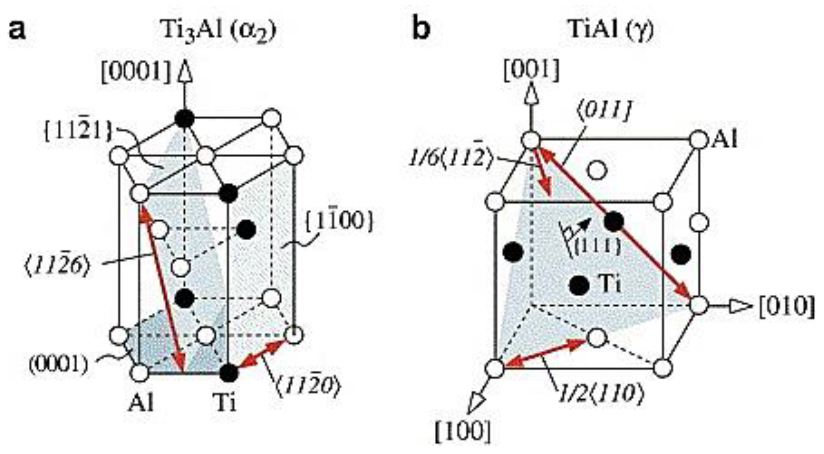
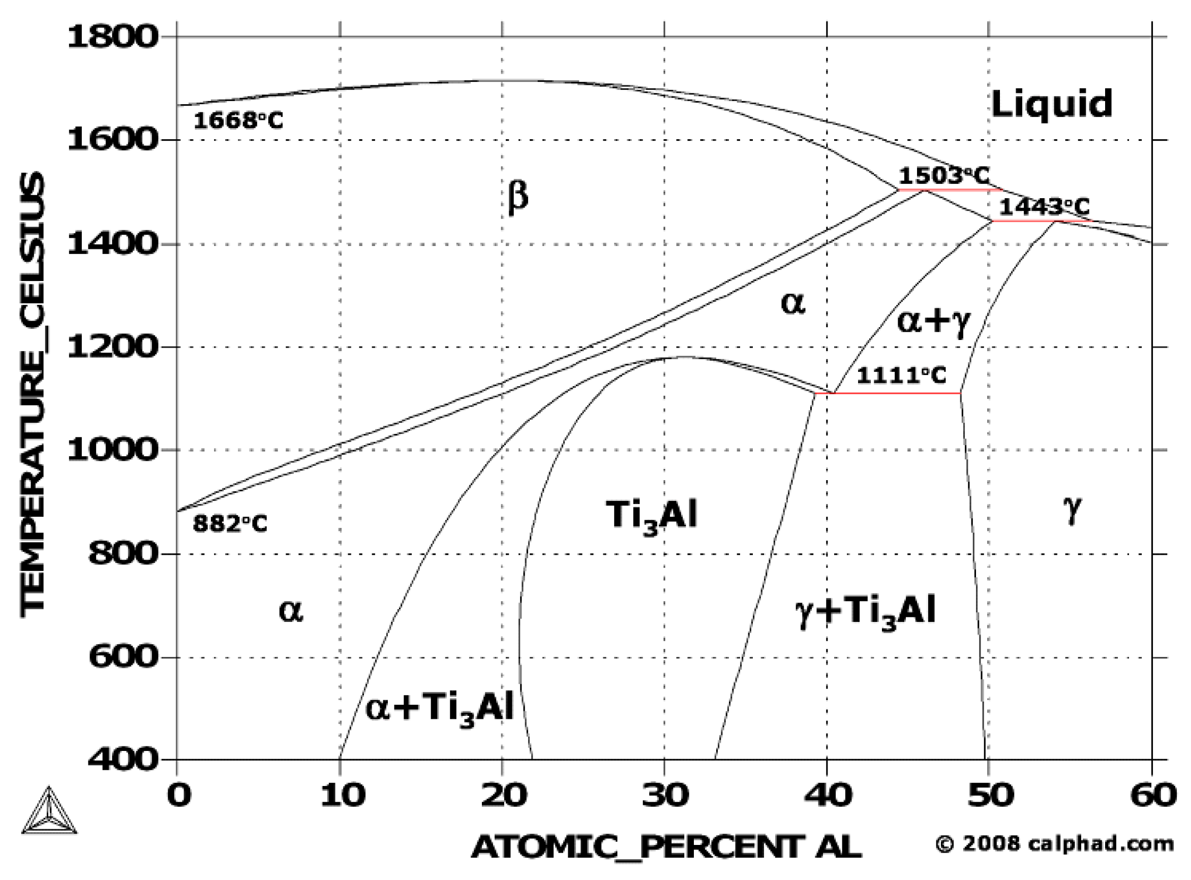
The α2-Ti3Al phase has a hexagonal symmetry of a D019 (Figure 9) structure with lattice parameters aord = 2adisor = 0.58 nm; cord = 0.48 nm. In a review by Djanarthany et al. [90], the last parameter is said to resemble that of an A3 type structure with a long-range ordering only in the direction perpendicular to the c-axis. Phase transformation according to β → α → α2 resulting from cooling forms the α2-phase, and orders between 1125 and 1150 °C [91]. As shown in Figure 10, the γ phase exists at a composition of ~48.5–60, α2 at ~24–34 and (γ + α2) at ~34–49 at. % Al. Although the α2-phase shows good strength at high temperatures, it has been found to be very brittle, much related to the high absorption level of O and hydrogen [85,92]. Contrarily, the γ-phase exhibits excellent resistance to oxidation with low-level O and hydrogen absorption and poor ductility at room temperature (RT). In recent studies [51,52,93], TiAl powders were consolidated using SPS and the phases mentioned above were obtained.
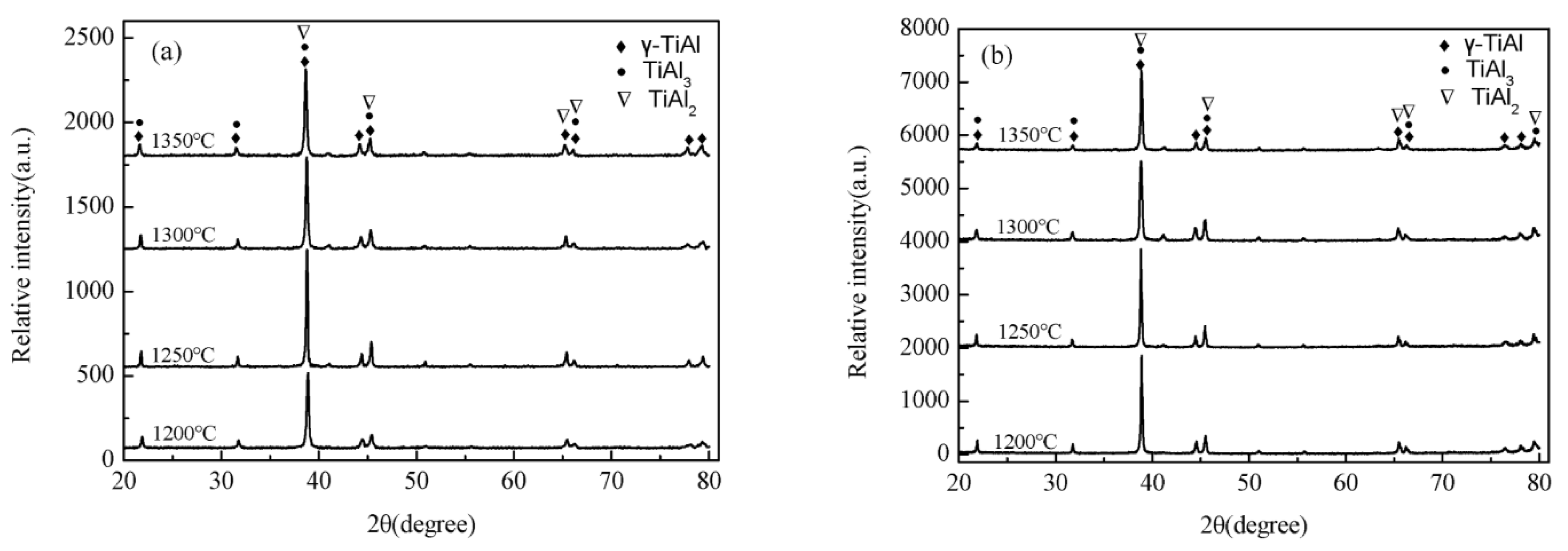
A high performance Ti–48Al–2Cr–2Nb alloy was produced by employing SPS to consolidate spherical pre-alloyed (SP powder) and ball milled pre-alloyed powders (MP powder). In this work, Wang et al. [93] carried out an analysis of the variations in density, microstructure and mechanical properties at different sintering temperatures. Similar phases as mentioned above (γ-TiAl, α2-Ti3Al) were achieved with additional TiAl2, TiAl3 for both the SP and MP powders. Additionally, the MP powder showed the presence of a Ti2Al phase. At sintering temperatures between 1200 and 1350 °C, the authors obtained γ-TiAl, TiAl3 and TiAl2 (see Figure 11).
In a similar study, Deng et al. [51] demonstrated a novel avenue for the manufacturing of Ti–45Al–8Nb alloys using CM and SPS. To prevent cold welding and promote powder homogeneity, elemental powders were ball milled for 16 h at a rotating speed of 200 rpm. Subsequently, the blended powders were cryomilled for 40 h at a speed of 350 rpm. The alloys were sintered using a heating rate of 100 °C/min up to sintering temperatures of 900, 1000 and 1100 °C, respectively. XRD analysis showed the presence of the much dominant γ-TiAl phase with minor amounts of the α2-Ti3Al phase.

4.2. Microstructures of TiAl

With a composition ranging from ~46–52 at. % of Al; the general microstructure is either a dual α2/γ or single pure γ-phase microstructure [95]. From the previously mentioned phases, with further processing and treatment characteristic microstructures referred to as equiaxed, duplex (DP), nearly lamellar (NL) and fully lamellar (FL) can be achieved [4]. The equiaxed structure contains a single phase γ-TiAl. The phase is stable in the region of the phase diagram above 50 at. %Al. Combined phase microstructure (commonly referred to as DP) made up of both α2 and γ is formed in the dual-phase section where the at. % of Al is between 46 and 50, depending on the heat treatment employed.
The single-phase γ consists of a continuous built-up of smaller equiaxed grains [83], and is formed in the γ + α2 phase field resulting in grain coarsening of existing γ grains [96]. This microstructure possesses good properties at high temperatures. This microstructure is very brittle and, therefore, not desired in structural or engineering applications [96,97]. The disadvantages are its poor room-temperature properties such as fracture toughness and ductility [95].
Heating in the two-phase region, followed by cooling results in a DP microstructure consisting of γ and lamella grains [98]. Grain refined DP microstructures have ambient strength and ductility with poor response to creep and fatigue at elevated temperatures [99]. A NL microstructure is formed in the α2+γ phase region where the α/γ ratio is greater than 1 whereas a FL microstructure is obtained in the pure α-phase field, followed by air-cooling to ambient temperature [96]. Optimum tensile strengths with superior low-cycle fatigue performance are observed in fine-grained NL microstructures, while a coarse microstructure significantly affects the fatigue performance at low-cycles [100]. Improved hardness and toughness is mostly observed in FL structures [101,102].

5. Microstructure-Property Relations

Fully densified γ-TiAl alloys with less residual porosity can be successfully produced using SPS. It has been proved countlessly [27,103,104,105,106] that the superior properties of these alloys can also be achieved by optimising SPS parameters. A fully densified γ-TiAl by SPS will have three distinctive microstructures namely, equiaxed γ grains, DP and lamella colonies having alternating layers of α2 and γ phase [9,103,107]. The lamella microstructure with (γ + α2) phase is the preferred in structural applications [85,108] due to the ease of controlling the distributions and amounts of the α2 and γ formed [109].
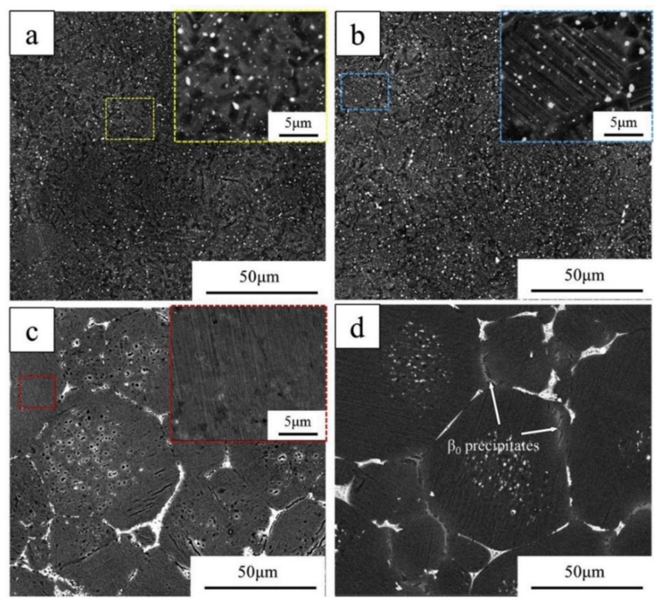
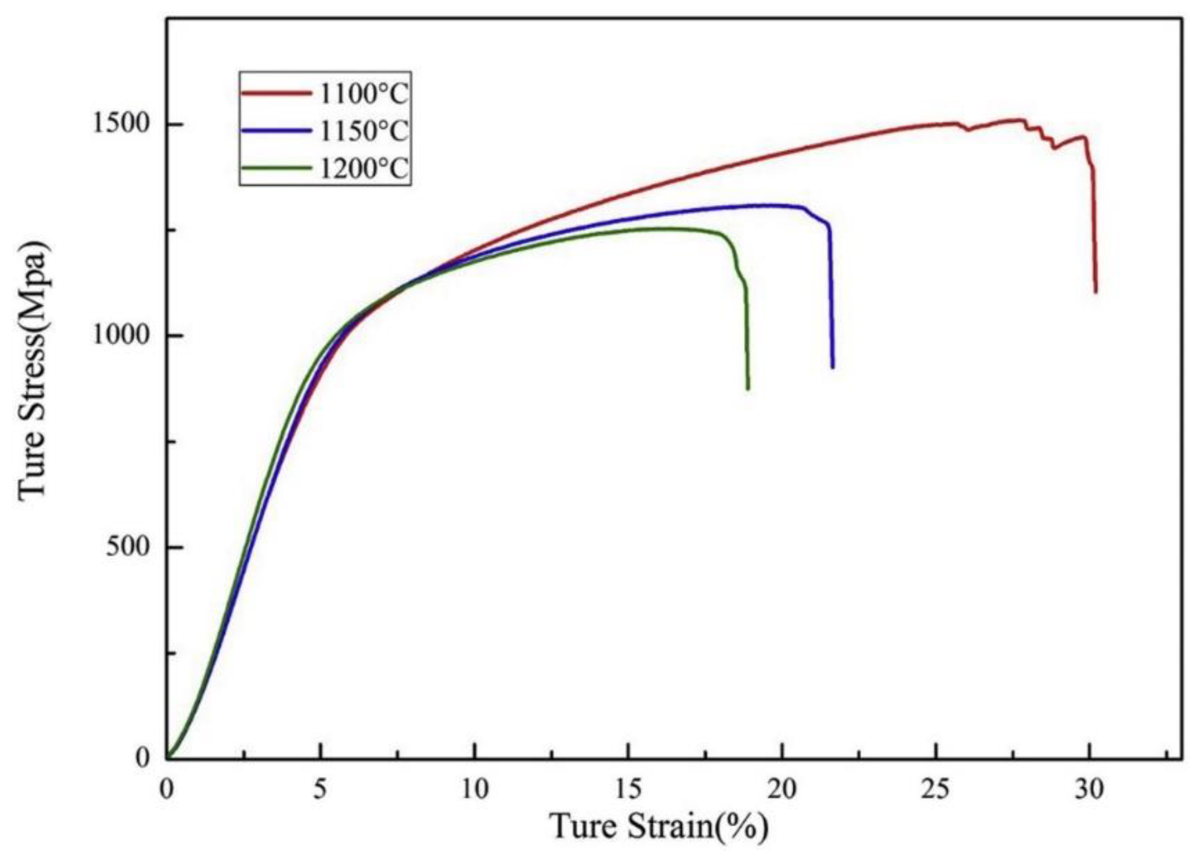
In a recent study, Gu and associates [27] produced a PA TiAl alloy with added yttrium using SPS. The microstructures (in Figure 12) obtained were DP, NL and FL by employing varying sintering temperatures ranging from 100 up to 1250 °C at a sintering pressure of 40 MPa. The compression results (Figure 13) obtained from the study showed that the compressive strength of the samples decreases with increasing sintering temperature. Furthermore, DP microstructure exhibited excellent yield, fracture strength and ultimate strain as compared to the samples with NL and FL microstructures. Wang et al. [103] investigated the effect of stresses and sintering temperature on the microstructural evolution and mechanical properties of a Ti–Al–Cr–Nb alloy produced by SPS. The authors reported that mechanical properties were reliant on the microstructures produced by the varied SPS conditions. An optimal true fracture strength of 1820 MPa and a plastic true strain of 32.6% were obtained for the alloy sintered at 1150 °C, consisting of a double phased and lamellar microstructure.
A NL microstructure has restricted RT ductility. According to a recent study, this effect can be defined by the difficult plastic deformation in γ/α2 colonies due high-volume percent of α2 present [106]. γ + α2 and DP microstructures offer enhanced yield strength, ductility and ultimate tensile strength at RT [18]. According to Couret and colleagues [18], these are governed by SPS parameter optimisation and addition of grain growth inhibitors such as boron. In the very same study, it was found that the poor strength and limited ductility in lamella microstructures can be attributed to the large grain size and lack of texture inhibiting propagation of dislocations in a preferred mode.
Voisin et al. [106], consolidated a TNM (γ-TiAl with Nb and Mo additions) alloy with chemical composition Ti–43.9Al–4Nb–0.95Mo-0.1B using SPS by varying sintering temperature of 1237–1429 °C. In addition, experiments on RT tensile deformation and creep at 700 °C employing stress of 300 MPa were conducted. A NL microstructure (in Figure 14a) was attained at sintering temperatures ranging from 1262 to 1336 °C. The highest ductility obtained from the results exhibited a fracture elongation of 0.86–0.9% for the specimen sintered at 1336 °C. TEM fractography also showed that the NL microstructure deformed using ordinary dislocation pileups and twinning (Figure 14c). Excellent creep resistance (Figure 14b) was obtained with lifetimes >2000 h at creep rates of <10−8 s−1, with the highest attained at a lifetime of ~4000 h for the alloy is that sintered at 1304 °C.
Another property of interest for TiAl alloys is oxidation. Resistance to oxidation, commonly known to as the resistance to corrosion at high temperatures, of γ-TiAl is said to be generally good at temperatures below 850 °C [110]. The kinetics of oxidation includes the formation of a non-protective mixed oxide scale of alumina (Al2O3) and titania (TiO2) on the surface of bare γ-TiAl alloys in a favourable condition and environment [111]. Simultaneous formation of Al2O3 and TiO2 occurs during the initial state of oxidation and thrive in the optimal growth direction [112]. Furthermore, TiO2 grows at a higher velocity compared to Al2O3 attributable to the low growth activation energy of TiO2 as compared to Al2O3. Additionally, the subsequent series of reactions are described as rapid and favour the formation of TiO2. However, below the TiO2 layer, an aluminium (Al)-rich layer exists because of Ti depletion. The oxide scale in TiAl consists of multi-layers of both TiO2 and Al2O3. A decrease in the oxidation resistance of γ-TiAl as mentioned by Dai et al. [112] can be as a result of the thickening of the multi-layered oxide film due to mass transportation, weakening the bond existing between the oxide layer and the substrate.
A FL microstructure seems to be the most preferred as far as oxidation resistance is concerned. However, the average lamella grain size and compositional variations are to be considered. A lamella grain size of 25–20 μm with Nb additions was reported to suppress diffusion activity in TiAl alloys [113,114]. The kinetics of oxidation involves the simultaneous formation of a non-protective mixed oxide scale of alumina (Al2O3) and titania (TiO2) on the surface of bare γ-TiAl alloys in a favourable condition and environment [111,112].
Several recent studies [113,115,116] aimed at improving the oxidation resistance of SPS produced TiAl alloys. Cobbinah and colleagues [115] investigated the effect of Ta additions (0.8, 4, and 8 at. %) on the isothermal oxidation resistance of a Ti–46.5Al (at. %) alloy produced by SPS. The results indicate that the superior resistance of the TiAl alloys is related to the formation of a non-porous and interconnected layer of Al2O3 at the interface of the metal-oxide. In works by Lu et al. [113], isothermal resistance at 1000 °C of SPS produced alloys of nominal composition Ti–45Al–8.5Nb–0.2B–0.2W–0.1Y and Ti–47.5Al–2.0V–1.0Cr were studied. A mixed oxide scale consisting of Al2O3/TiO2 was formed next to the spalled TiO2 layer for the Ti–47.5Al–2.5V–1.0Cr. Furthermore, the mixed scale produced proved to have no protective effect, resulting in high rates of oxidation (with mass gains of 51.06 mg/cm2) as compared to alloy Ti–45Al–8.5Nb–0.2B–0.2W–0.1Y (with only 2.27 mg/cm2 mass gain) tested under the same conditions. Relatively, the inner oxide scale of alloy Ti–45Al–8.5Nb–0.2B–0.2W–0.1Y exhibited an outer TiO2-rich layer with traces of Al2O3 and TiN. The addition of 8.5% Nb promoted the formation of a Nb-rich diffusion layer between the substrate and the oxide layer, further enhancing the oxidation resistance of the alloy.

6. Alloy Development

During the initial advances in two-phase binary alloys, it was acknowledged that these alloys cannot be utilised owing to their poor oxidation and creep resistance [43]. Consequently, this resulted in a vast number of investigations aimed at understanding the effect of alloy additions in binary TiAl on the microstructure-property relations. To date, four generations [97,117] of TiAl alloys have been developed.

6.1. 1st and 2nd Generation of TiAl alloys

In this generation of alloys, elements such as Cr, V, Mn were added to Ti–(42–48)Al (at. %) to produce ternary alloys. These alloys were further processed using heat and thermomechanical treatments to improve ductility measures. In a previous study of interest [118], it was reported that additions of up to 4 at. % of Cr to binary Ti–(44–54)Al alloys consisting of DP microstructures led to partial ductilization due to the occupancy of Cr in Al lattice sites. Cr additions also modified the Al partitioning and the thermal stabilisation of transformed α2 laths comparable to findings made when 0.4 at. % of V was added [119].
The 2nd generation of TiAl is based on the following composition [43]:
Ti–(45–48)Al–(1–3)X–(2–5)Y–(<1)Z
where X = Cr, Mn, Y = Nb, Ta, W, Mo; Z = Si, B, C.
The additions of the elements, as mentioned above, shift the position of the phase boundaries in the Ti–Al binary phase diagram [43,96]. Additions of element X improve the mechanical properties of TiAl alloys by increasing flow stress [120], reducing the stacking fault energy and thus enhancing the susceptibility of twinning [96]. Zhu et al. [121] studied the effect of Cr additions on the microstructure and nanohardness of Ti–48Al binary alloy produced using a single roller melt spinning and arc melting processing routes. With 2 at. % Cr, the microstructure of the alloy ribbons was lamella with equiaxed α2 and small B2 phase particles. Additions of up to 4 at. % Cr increases the B2 phase grain sizes and the lamella structure disappears. The nanohardness of the alloys increased also with additions of up to 4 at. % of Cr. Additions of V and Mn have been reported [122] to increase the fracture and yield stresses much related to grain refinement and solid solution strengthening (particularly for V additions).
Adding elements like Ta, Mo and W (Y additions) improve the oxidation and creep properties at elevated temperatures. Recently [115], additions of 4 and 8 at. % of Ta to an SPS produced Ti-46.5Al alloy promoted the formation of an Al2O3 layer severing as a diffusion barrier on the metal-oxide interface, hence, resulting in outstanding resistance to oxidation. For further reading on the effect Ta on the oxidation performance of TiAl, the reader is referred to [123,124,125,126]. Remarkable creep properties were obtained in some research work [127,128,129] when Ta and W were added to TiAl alloys. Z additions such as B promote grain refinement utilising retarding grain growth in the α-phase field [96]. Moreover, the strength and resistance to creep is improved through the formation of Ti3AlC perovskite precipitates when C is added. Numerous work has been conducted to date [130,131,132,133,134] on the effect B and C have on the microstructure and mechanical properties of TiAl, attesting to the above alloy addition benefits.

6.2. 3rd and 4th Generation of TiAl Alloys

This generation of alloys contains high Mo and or Nb contents to promote precipitation hardening and were developed for applications at elevated temperatures. The third generation of TiAl alloys follow the constitution below [43]:
Ti–(42–48)Al–(0–10)X–(0–3)Y–(0–1)Z–(0–0.5)RE
where X = Ta, Nb, Mn, Cr; Y = Zr, Hf, W, Mo; Z = C, B, Si and RE designates rare earth metals.
The additions of Zr is a known β-stabilizer, promoting occupancy of the Ti sites in the lattice of Ti–Al systems [135]. Furthermore, adding Zr to binary TiAl alloys improves compression strength. However, when added in the presence of Cr, the strength decreases with increasing elongation. Finally, phase evolutions occurring as a result of the existence of both Cr and Zr in Ti–43Al–4Nb–1Mo–0.1B (TNM-B1) alloy include the formation of ω, reduction of α2 and increments in the amount of β phases. Y rare earth metal additions promote grain refinement, thus improving ductility [136,137], elevated temperature deformability [138] and heat resistance [139]. The oxidation rate of TNM alloys can be reduced by ~0.1 at. % RE metal additions such as La or Er [140]. Conversely, additions of ~0.2 at. % of aforementioned RE metals can impair the resistance to oxidation through the formation of hillocks in the oxide scale.
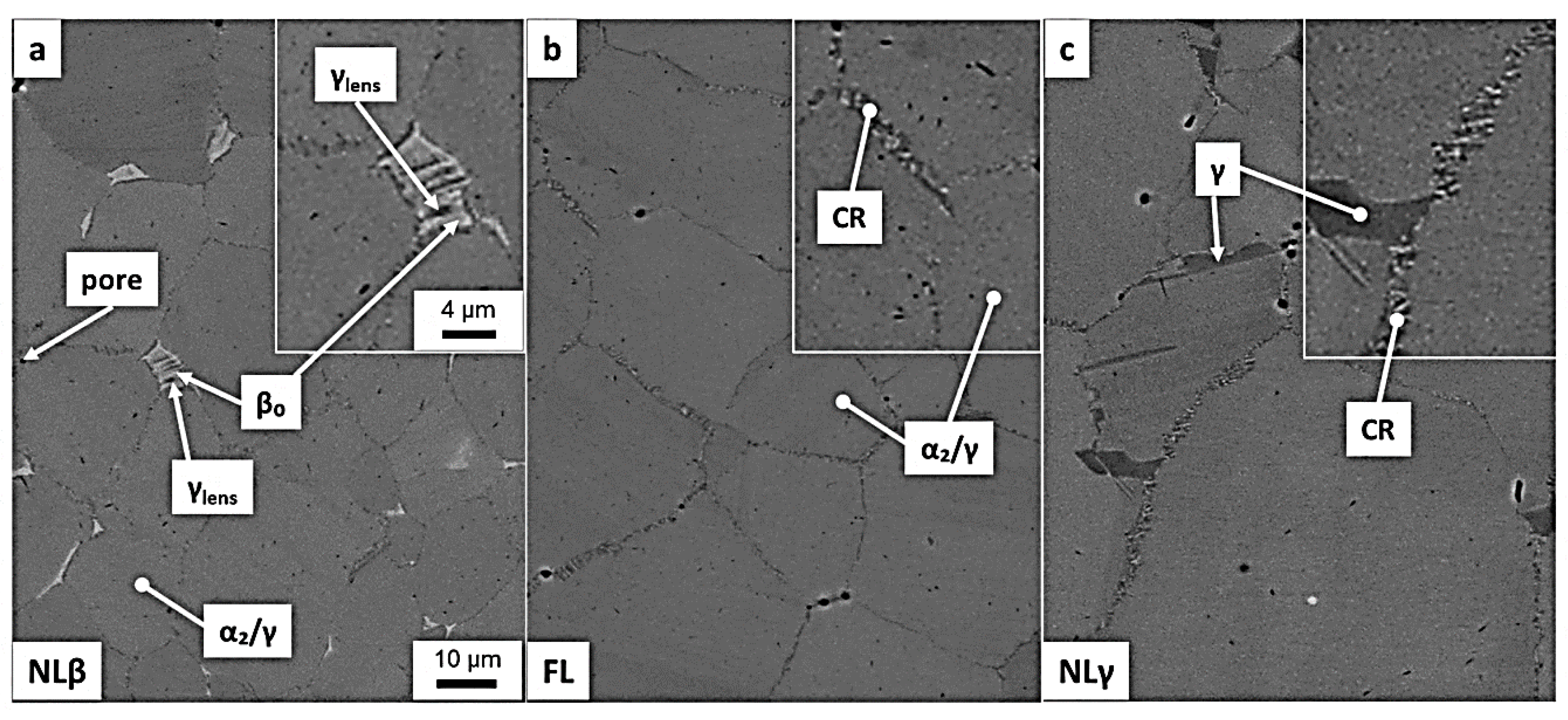
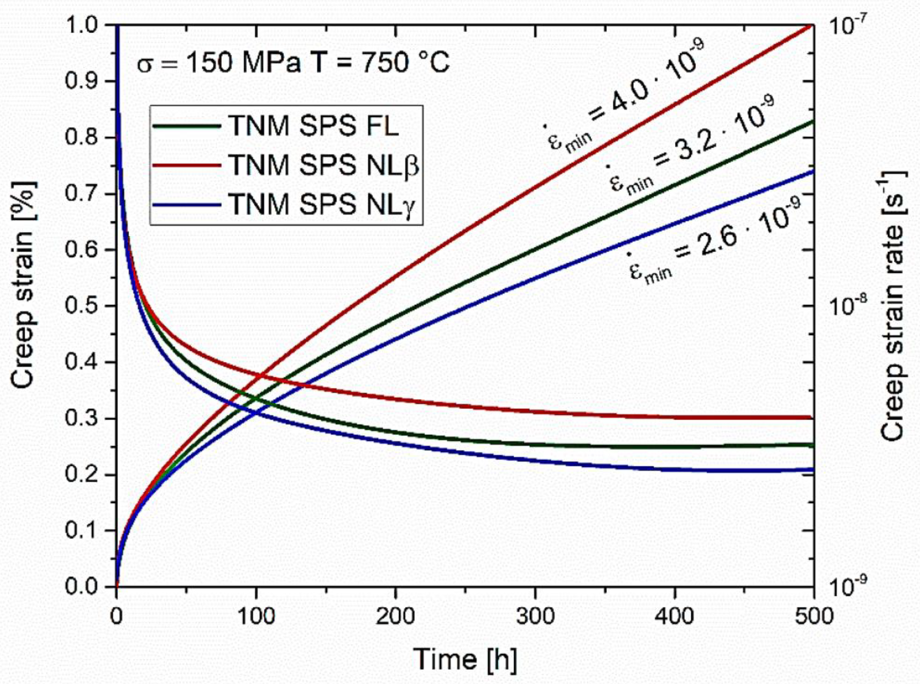
The fourth generation of TiAl, commonly referred to as TNM alloys, exhibit excellent oxidation resistance through Nb and or Ta additions and outstanding creep properties promoted by Mo additions. In addition, these alloys are said to have excellent workability making them universally applicable for various processing routes other than casting and hot forming such as additive manufacturing and SPS [141]. Some of the alloys developed to date include the β-solidifying Ti–43.5Al–4Nb–1Mo–0.1B [141], Ti–46Al–8Nb and Ti–46Al–8Ta [142]. Wimler et al. [141] studied the capabilities of SPS coupled with subsequent heat treatments to produce a Ti–43.5Al–4Nb–1Mo–0.1B alloy with strength and creep performance at 750 °C comparable to those produced by conventional processing techniques. After SPS consolidation of the gas atomised powder alloy at 1300 °C, the microstructure produced consisted of a refined and homogeneous NL γ and β0. Subsequent two-step heat treatments resulted in the formation of NL γ, FL and NL β0 structures (in Figure 15) decreasing the lamella spacing from 83 ± 7 in the as-sintered condition to 10 ± 3 nm. It was concluded that the strength and creep properties at 750 °C (in Figure 16) obtained can keep up with that of the conventional routes of processing.

7. Perspectives and Conclusions

The realisation of the process has been highlighted by remarkable accomplishments in the production of a refined microstructure of γ-TiAl since it offers prompt rates of both heating and cooling. Currently, research and development have shifted attention to TiAl powder forming techniques such as DMM, GA, and, amongst others, pre-alloying. MA and SPS can be coupled in the production of nanocrystalline intermetallic TiAl owing to the advantages of obtaining non-equilibrium and amorphous phases, ultrafine grain sizes and, at the same time, retaining the grain size during consolidation. As an added advantage, SPS uses shorter holding times to obtain fully densified material as compared to conventional processes such as HIP. Consolidation methods aimed at balancing microstructure and properties have also been explored.
However, SPS shows an impressive balance of microstructure and mechanical properties.
A significant challenge in as far as TiAl alloys are concerned is commercialisation and costs. Although limited applications have been achieved, the reality is that implementation of TiAl alloys in both the automobile and aerospace industries is an on-going challenge. Although TiAl were designed as candidates to replace the Ni-based superalloys, the gap existing between the two is quite recognisable from both the properties and production costs perspective. Much research has been dedicated to improving the ductility at RT for TiAl alloys through compositional variations, opting for manufacturing technologies and thermomechanical treatments. These attempts aimed at refining and altering the microstructures and morphologies of the produced alloys. Advanced PM techniques present the opportunity to manufacture near-net-shape components with improved mechanical properties. However, challenges exist concerning methods that can be employed to characterise PM produced TiAl alloys effectively. Although the future seems exciting for TiAl alloys produced using PM, implementation on an industrial scale seems to lag far behind.

Author Contributions

Writing—original draft preparation, N.F.M.; writing—review and editing, W.R.M. All authors have read and agreed to the published version of the manuscript.

Funding

This research was funded by National Research Foundation of South Africa, grant number 116368.

Conflicts of Interest

The authors declare no conflict of interest.

References

  1. Taub, A.I.; Fleischer, R.L. Intermetallic compounds for high-temperature structural use. Science 1989, 243, 616–621. [Google Scholar] [CrossRef] [PubMed]
  2. Wolff, I.M.; Hill, P.J. Platinum metals-based intermetallics for high-temperature service. Platin. Met. Rev. 2000, 44, 158–166. [Google Scholar]
  3. Muktinutalapati, N.R. Materials for gas turbines–an overview. In Advances in Gas Turbine Technology; IntechOpen: London, UK, 2011; Available online: https://www.intechopen.com/books/advances-in-gas-turbine-technology/materials-for-gas-turbines-an-overview (accessed on 1 May 2020).
  4. Leyens, C.; Peters, M. Titanium and Titanium Alloys: Fundamentals and Applications; John Wiley & Sons: Hoboken, NJ, USA, 2003. [Google Scholar]
  5. Clemens, H.; Smarsly, W. Light-weight intermetallic titanium aluminides–status of research and development. Adv. Mater. Res. 2011, 278, 551–556. [Google Scholar] [CrossRef] [Green Version]
  6. Voice, W. The future use of gamma titanium aluminides by Rolls-Royce. Aircr. Eng. Aerosp. Technol. 1999, 71, 337–340. [Google Scholar] [CrossRef]
  7. Bewlay, B.P.; Weimer, M.; Kelly, T.; Suzuki, A.; Subramanian, P.R. The science, technology, and implementation of TiAl alloys in commercial aircraft engines. MRS Online Proc. Libr. Arch. 2013, 1516, 49–58. [Google Scholar] [CrossRef]
  8. Loria, E.A. Quo vadis gamma titanium aluminide. Intermetallics 2001, 9, 997–1001. [Google Scholar] [CrossRef]
  9. Liu, B.; Liu, Y. 27-Powder metallurgy titanium aluminide alloys. In Titanium Powder Metallurgy; Elsevier Inc.: Amsterdam, The Netherlands, 2015; pp. 515–531. [Google Scholar]
  10. Lamirand, M.; Bonnentien, J.L.; Ferrière, G.; Guérin, S.; Chevalier, J.P. Relative effects of chromium and niobium on microstructure and mechanical properties as a function of oxygen content in TiAl alloys. Scr. Mater. 2007, 56, 325–328. [Google Scholar] [CrossRef]
  11. Wang, Q.; Ding, H.; Zhang, H.; Chen, R.; Guo, J.; Fu, H. Influence of Mn addition on the microstructure and mechanical properties of a directionally solidified γ-TiAl alloy. Mater. Charact. 2018, 137, 133–141. [Google Scholar] [CrossRef]
  12. Imayev, V.; Oleneva, T.; Imayev, R.; Christ, H.J.; Fecht, H.J. Microstructure and mechanical properties of low and heavy alloyed γ-TiAl + α2-Ti3Al based alloys subjected to different treatments. Intermetallics 2012, 26, 91–97. [Google Scholar] [CrossRef]
  13. Larsen, J.M.; Worth, B.D.; Balsone, S.J.; Jones, J.W. An Overview of the Structural Capability of Available Gamma Titanium Aluminide Alloys; U.S. Department of EnergyOffice of Scientific and Technical Informatio: Oak Ridge, TN, USA, 1995.
  14. Tang, J.; Huang, B.; Liu, W.; He, Y.; Zhou, K.; Wu, A.; Peng, K.; Qin, W.; Du, Y. A high ductility TiAl alloy made by two-step heat treatment. Mater. Res. Bull. 2003, 38, 2019–2024. [Google Scholar] [CrossRef]
  15. Lasalmonie, A. Intermetallics: Why is it so difficult to introduce them in gas turbine engines? Intermetallics 2006, 14, 1123–1129. [Google Scholar] [CrossRef]
  16. Lagos, M.A.; Agote, I. SPS synthesis and consolidation of TiAl alloys from elemental powders: Microstructure evolution. Intermetallics 2013, 36, 51–56. [Google Scholar] [CrossRef]
  17. Munir, Z.A.; Anselmi-Tamburini, U.; Ohyanagi, M. The effect of electric field and pressure on the synthesis and consolidation of materials: A review of the spark plasma sintering method. J. Mater. Sci. 2006, 41, 763–777. [Google Scholar] [CrossRef]
  18. Couret, A.; Molénat, G.; Galy, J.; Thomas, M. Microstructures and mechanical properties of TiAl alloys consolidated by spark plasma sintering. Intermetallics 2008, 16, 1134–1141. [Google Scholar] [CrossRef]
  19. Jaramillo, D.; Cuenca, R.; Juárez, F. Sintering comparison of NiCoCrAl-Ta powder processed by hot pressing and spark plasma. Powder Technol. 2012, 221, 264–270. [Google Scholar]
  20. Chang, I.; Zhao, Y. Advances in Powder Metallurgy: Properties, Processing and Applications; Elsevier: Amsterdam, The Netherlands, 2013. [Google Scholar]
  21. Martín, A.; Cepeda-Jiménez, C.M.; Pérez-Prado, M.T. Gas atomization of γ-TiAl Alloy Powder for Additive Manufacturing. Adv. Eng. Mater. 2020, 22, 1900594. [Google Scholar] [CrossRef]
  22. Neikov, O.D. Chapter 4-Atomization and Granulation. In Handbook of Non-Ferrous Metal Powders: Technologies and Applications; Neikov, O.D., Naboychenko, S.S., Yefimov, N.A., Second, E., Eds.; Elsevier: Oxford, UK, 2019; pp. 125–185. [Google Scholar]
  23. Gerling, R.; Clemens, H.; Schimansky, F.P. Powder Metallurgical Processing of Intermetallic Gamma Titanium Aluminides. Adv. Eng. Mater. 2004, 6, 23–38. [Google Scholar] [CrossRef]
  24. Sun, P.; Fang, Z.Z.; Zhang, Y.; Xia, Y. Review of the methods for production of spherical Ti and Ti alloy powder. JOM 2017, 69, 1853–1860. [Google Scholar] [CrossRef] [Green Version]
  25. Antony, L.V.M.; Reddy, R.G. Processes for production of high-purity metal powders. JOM 2003, 55, 14–18. [Google Scholar] [CrossRef]
  26. Franz, H.; Plochl, L.; Schimansky, F.P. Recent advances of titanium alloy powder production by ceramic-free inert gas atomization. In Proceedings of the Titanium 2008, Las Vegas, NV, USA, 21–24 September 2008. [Google Scholar]
  27. Gu, X.; Cao, F.; Liu, N.; Zhang, G.; Yang, D.; Shen, H.; Zhang, D.; Song, H.; Sun, J. Microstructural evolution and mechanical properties of a high yttrium containing TiAl based alloy densified by spark plasma sintering. J. Alloy. Compd. 2020, 819, 153264. [Google Scholar] [CrossRef]
  28. Liu, B.; Wang, M.; Du, Y.; Li, J. Size-Dependent Structural Properties of a High-Nb TiAl Alloy Powder. Materials 2020, 13, 161. [Google Scholar] [CrossRef] [PubMed] [Green Version]
  29. Xia, Y.; Zhao, J.L.; Qian, M. Spark Plasma Sintering of Ti-48Al-2Cr-2Nb Alloy Powder and Characterization of an Unexpected Phase. JOM 2019, 71, 2556–2563. [Google Scholar] [CrossRef]
  30. Wang, J.; Wang, Y.; Liu, Y.; Li, J.; He, L.; Zhang, C. Densification and microstructural evolution of a high niobium containing TiAl alloy consolidated by spark plasma sintering. Intermetallics 2015, 64, 70–77. [Google Scholar] [CrossRef]
  31. Xiao, S.L.; Jing, T.; Xu, L.J.; Chen, Y.Y.; Yu, H.B.; Han, J.C. Microstructures and mechanical properties of TiAl alloy prepared by spark plasma sintering. Trans. Nonferrous Met. Soc. China 2009, 19, 1423–1427. [Google Scholar] [CrossRef]
  32. Hadef, F. Synthesis and disordering of B2 TM-Al (TM=Fe, Ni, Co) intermetallic alloys by high energy ball milling: A review. Powder Technol. 2017, 311, 556–578. [Google Scholar] [CrossRef]
  33. Aliofkhazraei, M. Handbook of Mechanical Nanostructuring; John Wiley & Sons: Hoboken, NJ, USA, 2015. [Google Scholar]
  34. Suryanarayana, C.; Ivanov, E.; Boldyrev, V.V. The science and technology of mechanical alloying. Mater. Sci. Eng. A 2001, 304, 151–158. [Google Scholar] [CrossRef]
  35. Yadav, T.P.; Yadav, R.M.; Singh, D.P. Mechanical milling: A top down approach for the synthesis of nanomaterials and nanocomposites. Nanosci. Nanotechnol. 2012, 2, 22–48. [Google Scholar] [CrossRef] [Green Version]
  36. Oehring, M.; Klassen, T.; Bormann, R. The formation of metastable Ti–Al solid solutions by mechanical alloying and ball milling. J. Mater. Res. 1993, 8, 2819–2829. [Google Scholar] [CrossRef]
  37. Zhang, F.; Lu, L.; Lai, M.O. Study of thermal stability of mechanically alloyed Ti–75% Al powders. J. Alloy. Compd. 2000, 297, 211–218. [Google Scholar] [CrossRef]
  38. Wang, Y.; Zhang, C.; Liu, Y.; Zhao, S.; Li, J. Microstructure characterization and mechanical properties of TiAl-based alloys prepared by mechanical milling and spark plasma sintering. Mater. Charact. 2017, 128, 75–84. [Google Scholar] [CrossRef]
  39. Shulong, X.; Lijuan, X.; Hongbao, Y.; Yuyong, C. Effect of Y Addition on Microstructure and Mechanical Properties of TiAl-based Alloys Prepared by SPS. Rare Met. Mater. Eng. 2013, 42, 23–27. [Google Scholar] [CrossRef]
  40. Xiao, S.; Xu, L.; Chen, Y.; Yu, H. Microstructure and mechanical properties of TiAl-based alloy prepared by double mechanical milling and spark plasma sintering. Trans. Nonferrous Met. Soc. China 2012, 22, 1086–1091. [Google Scholar] [CrossRef]
  41. Suryanarayana, C. Mechanical Alloying: A Novel Technique to Synthesize Advanced Materials. Research 2019, 2019, 4219812. [Google Scholar] [CrossRef] [PubMed] [Green Version]
  42. Suryanarayana, C. Mechanical alloying and milling. Prog. Mater. Sci. 2001, 46, 1–184. [Google Scholar] [CrossRef]
  43. Clemens, H.; Mayer, S. Design, Processing, Microstructure, Properties, and Applications of Advanced Intermetallic TiAl Alloys. Adv. Eng. Mater. 2013, 15, 191–215. [Google Scholar] [CrossRef]
  44. Lu, L.; Lai, M.O.; Froes, F.H. The mechanical alloying of titanium aluminides. JOM 2002, 54, 62–64. [Google Scholar] [CrossRef]
  45. Forouzanmehr, N.; Karimzadeh, F.; Enayati, M.H. Study on solid-state reactions of nanocrystalline TiAl synthesized by mechanical alloying. J. Alloy. Compd. 2009, 471, 93–97. [Google Scholar] [CrossRef]
  46. Sim, K.H.; Wang, G.; Son, R.C.; Choe, S.L. Influence of mechanical alloying on the microstructure and mechanical properties of powder metallurgy Ti2AlNb-based alloy. Powder Technol. 2017, 317, 133–141. [Google Scholar] [CrossRef]
  47. Bohn, R.; Klassen, T.; Bormann, R. Mechanical behavior of submicron-grained γ-TiAl-based alloys at elevated temperatures. Intermetallics 2001, 9, 559–569. [Google Scholar] [CrossRef]
  48. Bhattacharya, P.; Bellon, P.; Averback, R.S.; Hales, S.J. Nanocrystalline TiAl powders synthesized by high-energy ball milling: Effects of milling parameters on yield and contamination. J. Alloy. Compd. 2004, 368, 187–196. [Google Scholar] [CrossRef]
  49. Lavernia, E.J.; Han, B.Q.; Schoenung, J.M. Cryomilled nanostructured materials: Processing and properties. Mater. Sci. Eng. 2008, 493, 207–214. [Google Scholar] [CrossRef]
  50. Witkin, D.B.; Lavernia, E.J. Synthesis and mechanical behavior of nanostructured materials via cryomilling. Prog. Mater. Sci. 2006, 51, 1–60. [Google Scholar] [CrossRef]
  51. Deng, H.; Chen, A.; Chen, L.; Wei, Y.; Xia, Z.; Tang, J. Bulk nanostructured Ti-45Al-8Nb alloy fabricated by cryomilling and spark plasma sintering. J. Alloy. Compd. 2019, 772, 140–149. [Google Scholar] [CrossRef]
  52. Shanmugasundaram, T.; Guyon, J.; Monchoux, J.P.; Hazotte, A.; Bouzy, E. On grain refinement of a γ-TiAl alloy using cryo-milling followed by spark plasma sintering. Intermetallics 2015, 66, 141–148. [Google Scholar] [CrossRef]
  53. Sun, Y.; Kulkarni, K.; Sachdev, A.K.; Lavernia, E.J. Synthesis of γ-TiAl by reactive spark plasma sintering of cryomilled Ti and Al powder blend, part I: Influence of processing and microstructural evolution. Met. Mater. Trans. A 2014, 45, 2750–2758. [Google Scholar] [CrossRef]
  54. Sun, Y.; Kulkarni, K.; Sachdev, A.K.; Lavernia, E.J. Synthesis of γ-TiAl by reactive spark plasma sintering of cryomilled Ti and Al powder blend: Part II: Effects of electric field and microstructure on sintering kinetics. Met. Mater. Trans. A 2014, 45, 2759–2767. [Google Scholar] [CrossRef]
  55. Guillon, O.; Gonzalez-Julian, J.; Dargatz, B.; Kessel, T.; Schierning, G.; Räthel, J.; Herrmann, M. Field-assisted sintering technology/spark plasma sintering: Mechanisms, materials, and technology developments. Adv. Eng. Mater. 2014, 16, 830–849. [Google Scholar] [CrossRef]
  56. Guyon, J.; Hazotte, A.; Monchoux, J.P.; Bouzy, E. Effect of powder state on spark plasma sintering of TiAl alloys. Intermetallics 2013, 34, 94–100. [Google Scholar] [CrossRef]
  57. Chen, F.; Yang, S.; Wu, J.; Galaviz Perez, J.A.; Shen, Q.; Schoenung, J.M.; Lavernia, E.J.; Zhang, L. Spark plasma sintering and densification mechanisms of conductive ceramics under coupled thermal/electric fields. J. Am. Ceram. Soc. 2015, 98, 732–740. [Google Scholar] [CrossRef]
  58. Matizamhuka, W.R. Fabrication of Fine-Grained Functional Ceramics by Two-Step Sintering or Spark Plasma Sintering (SPS). In Sintering [Working Title]; IntechOpen: London, UK, 2019. [Google Scholar]
  59. Matizamhuka, W.R. Spark plasma sintering (SPS)-an advanced sintering technique for structural nanocomposite materials. J. South. African Inst. Min. Met. 2016, 116, 1171–1180. [Google Scholar] [CrossRef]
  60. Suárez, M.; Fernández, A.; Menéndez, J.L.; Torrecillas, R.; Kessel, H.U.; Hennicke, J.; Kirchner, R.; Kessel, T. Challenges and opportunities for spark plasma sintering: A key technology for a new generation of materials. Sinter. Appl. 2013, 13, 319–342. [Google Scholar]
  61. Marder, R.; Estournès, C.; Chevallier, G.; Chaim, R. Spark and plasma in spark plasma sintering of rigid ceramic nanoparticles: A model system of YAG. J. Eur. Ceram. Soc. 2015, 35, 211–218. [Google Scholar] [CrossRef] [Green Version]
  62. Marder, R.; Estournès, C.; Chevallier, G.; Chaim, R. Plasma in spark plasma sintering of ceramic particle compacts. Scr. Mater. 2014, 82, 57–60. [Google Scholar] [CrossRef] [Green Version]
  63. Saunders, T.; Grasso, S.; Reece, M.J. Plasma formation during electric discharge (50V) through conductive powder compacts. J. Eur. Ceram. Soc. 2015, 35, 871–877. [Google Scholar] [CrossRef]
  64. Rahaman, M.N. Ceramic Processing and Sintering; CRC press: Boca Raton, FL, USA, 2003. [Google Scholar]
  65. Olevsky, E.A.; Kandukuri, S.; Froyen, L. Consolidation enhancement in spark-plasma sintering: Impact of high heating rates. J. Appl. Phys. 2007, 102, 114913. [Google Scholar] [CrossRef]
  66. Manière, C.; Torresani, E.; Olevsky, E.A. Simultaneous spark plasma sintering of multiple complex shapes. Materials 2019, 12, 557. [Google Scholar] [CrossRef] [Green Version]
  67. Manière, C.; Durand, L.; Weibel, A.; Estournès, C. Spark-plasma-sintering and finite element method: From the identification of the sintering parameters of a submicronic α-alumina powder to the development of complex shapes. Acta Mater. 2016, 102, 169–175. [Google Scholar] [CrossRef] [Green Version]
  68. Voisin, T.; Monchoux, J.P.; Durand, L.; Karnatak, N.; Thomas, M.; Couret, A. An Innovative Way to Produce γ-TiAl Blades: Spark Plasma Sintering. Adv. Eng. Mater. 2015, 17, 1408–1413. [Google Scholar] [CrossRef]
  69. Manière, C.; Durand, L.; Weibel, A.; Chevallier, G.; Estournès, C. A sacrificial material approach for spark plasma sintering of complex shapes. Scr. Mater. 2016, 124, 126–128. [Google Scholar] [CrossRef]
  70. Manière, C.; Nigito, E.; Durand, L.; Weibel, A.; Beynet, Y.; Estournès, C. Spark plasma sintering and complex shapes: The deformed interfaces approach. Powder Technol. 2017, 320, 340–345. [Google Scholar] [CrossRef] [Green Version]
  71. Olevsky, E.A.; Garcia-Cardona, C.; Bradbury, W.L.; Haines, C.D.; Martin, D.G.; Kapoor, D. Fundamental Aspects of Spark Plasma Sintering: II. Finite Element Analysis of Scalability. J. Am. Ceram. Soc. 2012, 95, 2414–2422. [Google Scholar] [CrossRef]
  72. Voisin, T.; Durand, L.; Karnatak, N.; Le Gallet, S.; Thomas, M.; Le Berre, Y.; Castagné, J.F.; Couret, A. Temperature control during Spark Plasma Sintering and application to up-scaling and complex shaping. J. Mater. Process. Technol. 2013, 213, 269–278. [Google Scholar] [CrossRef]
  73. Franceschin, G.; Flores-Martínez, N.; Vázquez-Victorio, G.; Ammar, S.; Valenzuela, R. Sintering and reactive sintering by spark plasma sintering (SPS). In Sintering of Functional Materials; IntechOpen: London, UK, 2017; Available online: https://www.intechopen.com/books/sintering-of-functional-materials/sintering-and-reactive-sintering-by-spark-plasma-sintering-sps- (accessed on 1 May 2020).
  74. Isobe, T.; Daimon, K.; Sato, T.; Matsubara, T.; Hikichi, Y.; Ota, T. Spark plasma sintering technique for reaction sintering of Al2O3/Ni nanocomposite and its mechanical properties. Ceram. Int. 2008, 34, 213–217. [Google Scholar] [CrossRef]
  75. Waseem, O.A.; Lee, J.; Lee, H.M.; Ryu, H.J. The effect of Ti on the sintering and mechanical properties of refractory high-entropy alloy TixWTaVCr fabricated via spark plasma sintering for fusion plasma-facing materials. Mater. Chem. Phys. 2018, 210, 87–94. [Google Scholar] [CrossRef]
  76. Meir, S.; Kalabukhov, S.; Froumin, N.; Dariel, M.P.; Frage, N. Synthesis and densification of transparent magnesium aluminate spinel by SPS processing. J. Am. Ceram. Soc. 2009, 92, 358–364. [Google Scholar] [CrossRef]
  77. Martins, D.; Grumbach, F.; Simoulin, A.; Sallot, P.; Mocellin, K.; Bellet, M.; Estournès, C. Spark plasma sintering of a commercial TiAl 48-2-2 powder: Densification and creep analysis. Mater. Sci. Eng. A 2018, 711, 313–316. [Google Scholar] [CrossRef] [Green Version]
  78. Anselmi-Tamburini, U.; Garay, J.E.; Munir, Z.A. Fast low-temperature consolidation of bulk nanometric ceramic materials. Scr. Mater. 2006, 54, 823–828. [Google Scholar] [CrossRef]
  79. Lenel, F. Resistance sintering under pressure. JOM 1955, 7, 158–167. [Google Scholar] [CrossRef]
  80. Weissler, G.A. Resistance sintering with alumina dies. Int. J. Powder Met. Powder Technol. 1981, 17, 107–118. [Google Scholar]
  81. Herrmann, M.; Schulz, I.; Bales, A.; Sempf, K.; Hoehn, S. “Snow flake” structures in silicon nitride ceramics–Reasons for large scale optical inhomogeneities. J. Eur. Ceram. Soc. 2008, 28, 1049–1056. [Google Scholar] [CrossRef]
  82. Langer, J.; Hoffmann, M.J.; Guillon, O. Electric Field-Assisted Sintering in Comparison with the Hot Pressing of Yttria-Stabilized Zirconia. J. Am. Ceram. Soc. 2011, 94, 24–31. [Google Scholar] [CrossRef]
  83. Westbrook, J.H.; Fleischer, R.L. Crystal Structures of Intermetallic Compounds; John Wiley & Sons: Hoboken, NJ, USA, 2000. [Google Scholar]
  84. Paufler, P.J.H. Westbrook, R.L. Intermetallic Compounds Principles and Practice; John Wiley & Sons: Hoboken, NJ, USA, 1995. [Google Scholar]
  85. Cobbinah, P.V.; Matizamhuka, W.R. Solid-State Processing Route, Mechanical Behaviour, and Oxidation Resistance of TiAl Alloys. Adv. Mater. Sci. Eng. 2019, 2019, 1–21. [Google Scholar] [CrossRef] [Green Version]
  86. Froes, F.H.; Suryanarayana, C.; Eliezer, D. Synthesis, properties and applications of titanium aluminides. J. Mater. Sci. 1992, 27, 5113–5140. [Google Scholar] [CrossRef]
  87. McCullough, C.; Valencia, J.J.; Levi, C.G.; Mehrabian, R. Phase equilibria and solidification in Ti-Al alloys. Acta Met. 1989, 37, 1321–1336. [Google Scholar] [CrossRef]
  88. Jones, S.A.; Shull, R.D.; McAlister, A.J.; Kaufman, M.J. Microstructural studies of Ti-Al alloys in the vicinity of the “eutectoid” reaction (α → α2 γ). Scr. Met. 1988, 22, 1235–1240. [Google Scholar] [CrossRef]
  89. JH, P. Phase Reactions and Processing in the Ti-Al Based Intermetallics. ISIJ Int. 1991, 31, 1080–1087. [Google Scholar]
  90. Djanarthany, S.; Viala, J.C.; Bouix, J. An overview of monolithic titanium aluminides based on Ti3Al and TiAl. Mater. Chem. Phys. 2001, 72, 301–319. [Google Scholar] [CrossRef]
  91. Sastry, S.M.L.; Lipsitt, H.A. Ordering transformations and mechanical properties of Ti 3 Ai and Ti 3 Al-Nb alloys. Met. Trans. A 1977, 8, 1543–1552. [Google Scholar] [CrossRef]
  92. Sarkar, S.; Datta, S.; Das, S.; Basu, D. Oxidation protection of gamma-titanium aluminide using glass–ceramic coatings. Surf. Coat. Technol. 2009, 203, 1797–1805. [Google Scholar] [CrossRef]
  93. Wang, Z.; Sun, H.; Du, Y.; Yuan, J. Effects of Powder Preparation and Sintering Temperature on Properties of Spark Plasma Sintered Ti-48Al-2Cr-8Nb Alloy. Metals 2019, 9, 861. [Google Scholar] [CrossRef] [Green Version]
  94. Werwer, M.; Kabir, R.; Cornec, A.; Schwalbe, K.H. Fracture in lamellar TiAl simulated with the cohesive model. Eng. Fract. Mech. 2007, 74, 2615–2638. [Google Scholar] [CrossRef] [Green Version]
  95. Stoloff, N.S.; Sikka, V.K. Physical Metallurgy and Processing of Intermetallic Compounds; Springer Science & Business Media: Berlin/Heidelberg, Germany, 2012. [Google Scholar]
  96. Kothari, K.; Radhakrishnan, R.; Wereley, N.M. Advances in gamma titanium aluminides and their manufacturing techniques. Prog. Aerosp. Sci. 2012, 55, 1–16. [Google Scholar] [CrossRef]
  97. Kim, Y.W.; Dimiduk, D.M. Progress in the understanding of gamma titanium aluminides. JOM 1991, 43, 40–47. [Google Scholar] [CrossRef]
  98. Wu, X. Review of alloy and process development of TiAl alloys. Eur. Congr. Adv. Mater. Process. 2006, 14, 1114–1122. [Google Scholar] [CrossRef]
  99. Hernandez, J.; Murr, L.E.; Gaytan, S.M.; Martinez, E.; Medina, F.; Wicker, R.B. Microstructures for two-phase gamma titanium aluminide fabricated by electron beam melting. Met. Microstruct Anal. 2012, 1, 14–27. [Google Scholar] [CrossRef] [Green Version]
  100. Recina, V. Mechanical Properties of Gamma Titanium Aluminides; Chalmers University of Technology: Gothenburg, Sweden, 2000. [Google Scholar]
  101. Wang, G.X.; Dahms, M. Influence of heat treatment on microstructure of Ti-35wt%Al prepared by elemental powder metallurgy. Scr. Met. Mater. 1992, 26, 717–722. [Google Scholar] [CrossRef]
  102. Gupta, R.K.; Pant, B.; Sinha, P.P. Theory and practice of γ α 2 Ti aluminide: A review. Trans. Indian Inst. Met. 2014, 67, 143–165. [Google Scholar] [CrossRef]
  103. Wang, D.; Yuan, H.; Qiang, J. The microstructure evolution, mechanical properties and densification mechanism of TiAl-based alloys prepared by spark plasma sintering. Metals 2017, 7, 201. [Google Scholar] [CrossRef] [Green Version]
  104. Wang, D.; Zhao, H.; Zheng, W. Effect of temperature-related factors on densification, microstructure and mechanical properties of powder metallurgy TiAl-based alloys. Adv. Powder Technol. 2019, 30, 2555–2563. [Google Scholar] [CrossRef]
  105. Liu, J.; Li, Z.; Yan, H.; Jiang, K. Spark Plasma Sintering of Alumina Composites with Graphene Platelets and Silicon Carbide Nanoparticles. Adv. Eng. Mater. 2014, 16, 1111–1118. [Google Scholar] [CrossRef]
  106. Voisin, T.; Monchoux, J.P.; Hantcherli, M.; Mayer, S.; Clemens, H.; Couret, A. Microstructures and mechanical properties of a multi-phase β-solidifying TiAl alloy densified by spark plasma sintering. Acta Mater. 2014, 73, 107–115. [Google Scholar] [CrossRef]
  107. Zhang, C.; Zhang, K.; Wang, G. Dependence of heating rate in PCAS on microstructures and high temperature deformation properties of γ-TiAl intermetallic alloys. Intermetallics 2010, 18, 834–840. [Google Scholar] [CrossRef]
  108. Mphahlele, M.R.; Olevsky, E.A.; Olubambi, P.A. Chapter 12-Spark plasma sintering of near net shape titanium aluminide: A review. In Spark Plasma Sinter; Elsevier Inc.: Amsterdam, The Netherlands, 2019; pp. 281–299. [Google Scholar]
  109. Appel, F.; Clemens, H.; Fischer, F.D. Modeling concepts for intermetallic titanium aluminides. Prog. Mater. Sci. 2016, 81, 55–124. [Google Scholar] [CrossRef]
  110. Bewlay, B.P.; Nag, S.; Suzuki, A.; Weimer, M.J. TiAl alloys in commercial aircraft engines. Mater. High Temp. 2016, 33, 549–559. [Google Scholar] [CrossRef]
  111. Pflumm, R.; Friedle, S.; Schütze, M. Oxidation protection of γ-TiAl-based alloys–A review. Intermetallics 2015, 56, 1–14. [Google Scholar] [CrossRef]
  112. Dai, J.; Zhu, J.; Chen, C.; Weng, F. High temperature oxidation behavior and research status of modifications on improving high temperature oxidation resistance of titanium alloys and titanium aluminides: A review. J. Alloy. Compd. 2016, 685, 784–798. [Google Scholar] [CrossRef]
  113. Lu, X.; He, X.B.; Zhang, B.; Qu, X.H.; Zhang, L.; Guo, Z.X.; Tian, J.J. High-temperature oxidation behavior of TiAl-based alloys fabricated by spark plasma sintering. J. Alloy. Compd. 2009, 478, 220–225. [Google Scholar] [CrossRef]
  114. Kumpfert, J.; Kim, Y.W.; Dimiduk, D.M. Effect of microstructure on fatigue and tensile properties of the gamma TiAl alloy Ti-46.5Al-3.0Nb-2.1Cr-0.2W. Mater. Sci. Eng. A 1995, 192, 465–473. [Google Scholar] [CrossRef]
  115. Cobbinah, P.V.; Matizamhuka, W.; Machaka, R.; Shongwe, M.B.; Yamabe-Mitarai, Y. The effect of Ta additions on the oxidation resistance of SPS-produced TiAl alloys. Int. J. Adv. Manuf. Technol. 2020, 106, 3203–3215. [Google Scholar] [CrossRef]
  116. Kenel, C.; Lis, A.; Dawson, K.; Stiefel, M.; Pecnik, C.; Barras, J.; Colella, A.; Hauser, C.; Tatlock, G.J.; Leinenbach, C.; et al. Mechanical performance and oxidation resistance of an ODS γ-TiAl alloy processed by spark plasma sintering and laser additive manufacturing. Intermetallics 2017, 91, 169–180. [Google Scholar] [CrossRef]
  117. Kim, Y.W. Ordered intermetallic alloys, part III: Gamma titanium aluminides. JOM 1994, 46, 30–39. [Google Scholar] [CrossRef]
  118. Huang, S.C.; Hall, E.L. The effects of Cr additions to binary TiAl-base alloys. Met. Trans. A 1991, 22, 2619–2627. [Google Scholar] [CrossRef]
  119. Huang, S.C.; Hall, E.L. Characterization of the effect of vanadium additions to TiAl base alloys. Acta Met. Mater. 1991, 39, 1053–1060. [Google Scholar] [CrossRef]
  120. Hashimoto, K. High-Temperature Tensile Properties of Ti-Al-X (X=Cr,W) Consisting of Î ± 2, Î2 and Î3 in Three Phases. Mater. Sci. Forum 2012, 706–709, 1066–1070. [Google Scholar] [CrossRef]
  121. Zhu, D.D.; Wang, H.W.; Qi, J.Q.; Zou, C.M.; Wei, Z.J. Effect of Cr addition on microstructures and nanohardness of rapidly solidified Ti–48Al alloy. Mater. Sci. Technol. 2012, 28, 1385–1390. [Google Scholar] [CrossRef]
  122. Kawabata, T.; Fukai, H.; Izumi, O. Effect of ternary additions on mechanical properties of TiAl. Acta Mater. 1998, 46, 2185–2194. [Google Scholar] [CrossRef]
  123. Pelachová, T.; Lapin, J. Cyclic oxidation behaviour of intermetallic Ti-46Al-8Ta alloy in air. Kov. Mater 2015, 53, 415–422. [Google Scholar] [CrossRef] [Green Version]
  124. Yuanyuan, L.; Weidong, Z.; Zhengping, X.; Xiaonan, M.; Yingli, Y.; Jinping, W.; Hangbiao, S. Microstructure, mechanical properties and oxidation behavior of a hot-extruded TiAl containing Ta. Rare Met. Mater. Eng. 2015, 44, 282–287. [Google Scholar] [CrossRef]
  125. Mitoraj, M.; Godlewska, E.M. Oxidation of Ti–46Al–8Ta in air at 700 °C and 800 °C under thermal cycling conditions. Intermetallics 2013, 34, 112–121. [Google Scholar] [CrossRef]
  126. Popela, T.; Vojtěch, D.; Novák, P.; Knotek, V.; Průša, F.; Michalcová, A.; Novák, M.; Šerák, J. High-temperature oxidation of Ti-Al-Ta and Ti-Al-Nb alloys. Metal 2010, 18, 1–4. [Google Scholar]
  127. Lapin, J.; Pelachová, T.; Dománková, M. Long-term creep behaviour of cast TiAl-Ta alloy. Intermetallics 2018, 95, 24–32. [Google Scholar] [CrossRef]
  128. Lapin, J.; Pelachová, T.; Dománková, M. Creep behaviour of a new air-hardenable intermetallic Ti–46Al–8Ta alloy. Intermetallics 2011, 19, 814–819. [Google Scholar] [CrossRef]
  129. Hodge, A.M.; Hsiung, L.M.; Nieh, T.G. Creep of nearly lamellar TiAl alloy containing W. Scr. Mater. 2004, 51, 411–415. [Google Scholar] [CrossRef] [Green Version]
  130. Fang, H.; Chen, R.; Yang, Y.; Tan, Y.; Su, Y.; Ding, H.; Guo, J. Effects of Boron On Microstructure Evolution and Mechanical Properties in Ti46Al8Nb2.6C0.8Ta Alloys. Adv. Eng. Mater. 2019, 21, 1900143. [Google Scholar] [CrossRef]
  131. Li, M.; Xiao, S.; Xiao, L.; Xu, L.; Tian, J.; Chen, Y. Effects of carbon and boron addition on microstructure and mechanical properties of TiAl alloys. J. Alloy. Compd. 2017, 728, 206–221. [Google Scholar] [CrossRef]
  132. Čegan, T.; Szurman, I. Thermal stability and precipitation strengthening of fully lamellar Ti-45Al-5Nb-0.2 B-0.75 C alloy. Met. Mater. 2018, 55, 421–430. [Google Scholar]
  133. Wang, Q.; Ding, H.; Zhang, H.; Chen, R.; Guo, J.; Fu, H. Variations of microstructure and tensile property of γ-TiAl alloys with 0–0.5at% C additives. Mater. Sci. Eng. A 2017, 700, 198–208. [Google Scholar] [CrossRef]
  134. Li, M.; Xiao, S.; Chen, Y.; Xu, L.; Tian, J. The effect of boron addition on the high-temperature properties and microstructure evolution of high Nb containing TiAl alloys. Mater. Sci. Eng. A 2018, 733, 190–198. [Google Scholar] [CrossRef]
  135. Bazhenov, V.E.; Kuprienko, V.S.; Fadeev, A.V.; Bazlov, A.I.; Belov, V.D.; Titov, A.Y.; Koltygin, A.V.; Komissarov, A.A.; Plisetskaya, I.V.; Logachev, I.A. Influence of Y and Zr on TiAl43Nb4Mo1B0. 1 titanium aluminide microstructure and properties. Mater. Sci. Technol. 2020, 36, 548–555. [Google Scholar] [CrossRef]
  136. Xu, W.; Huang, K.; Wu, S.; Zong, Y.; Shan, D. Influence of Mo content on microstructure and mechanical properties of β-containing TiAl alloy. Trans. Nonferrous Met. Soc. China 2017, 27, 820–828. [Google Scholar] [CrossRef]
  137. Wu, Y.; Hwang, S.K. Microstructural refinement and improvement of mechanical properties and oxidation resistance in EPM TiAl-based intermetallics with yttrium addition. Acta Mater. 2002, 50, 1479–1493. [Google Scholar] [CrossRef]
  138. Kong, F.T.; Chen, Y.Y.; Li, B.H. Influence of yttrium on the high temperature deformability of TiAl alloys. Mater. Sci. Eng. A 2009, 499, 53–57. [Google Scholar] [CrossRef]
  139. Stringer, J. The reactive element effect in high-temperature corrosion. Mater. Sci. Eng. A 1989, 120, 129–137. [Google Scholar] [CrossRef]
  140. Hadi, M.; Bayat, O.; Meratian, M.; Shafyei, A.; Ebrahimzadeh, I. Oxidation Properties of a Beta-Stabilized TiAl Alloy Modified by Rare Earth Elements. Oxid. Met. 2018, 90, 421–434. [Google Scholar] [CrossRef]
  141. Wimler, D.; Lindemann, J.; Clemens, H.; Mayer, S. Microstructural Evolution and Mechanical Properties of an Advanced γ-TiAl Based Alloy Processed by Spark Plasma Sintering. Materials 2019, 12, 1523. [Google Scholar] [CrossRef] [Green Version]
  142. Saage, H.; Huang, A.J.; Hu, D.; Loretto, M.H.; Wu, X. Microstructures and tensile properties of massively transformed and aged Ti46Al8Nb and Ti46Al8Ta alloys. Intermetallics 2009, 17, 32–38. [Google Scholar] [CrossRef]
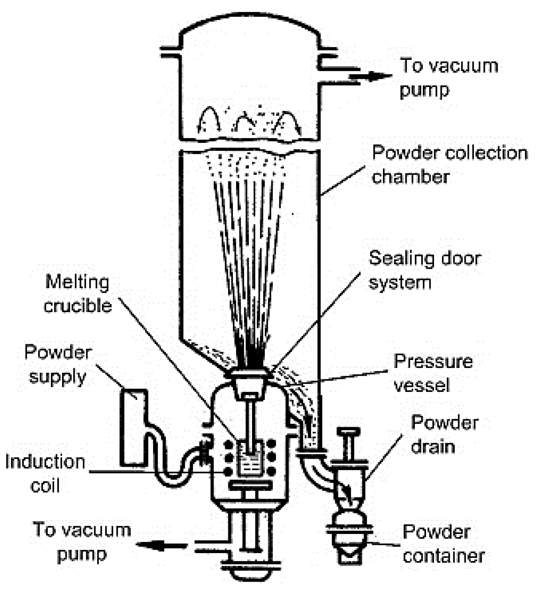
Figure 1. Gas atomisation (GA) schematic, reproduced from [22], with permission from Elsevier, 2019.
Metals 10 01080 g001
Figure 2. Scanning electron microscope (SEM) images of GA produced Ti4522XD powders with sizes: (a) d  < 45 μm; (b) 45 μm < d < 100 μm; and (c) 100 μm < d  < 150 μm, reproduced from [21], with permission from John Wiley and Sons, 2020.
Metals 10 01080 g002
Figure 3. (a) Cryomilling (CM) apparatus representation; (b) a customised 500 g capacity mill in operation, reproduced from [50], with permission from Elsevier, 2006.
Metals 10 01080 g003
Figure 4. Spark plasma sintering (SPS) process representation, reproduced from [57], with permission from John Wiley and Sons, 2014.
Metals 10 01080 g004
Figure 5. Representation of the graphite mold assembly with (a) punches in position and (b) side view of the mold, reproduced from [68], with permission from John Wiley and Sons, 2015.
Metals 10 01080 g005
Figure 6. An illustration of the sacrificial material approach with (a) showing the desired geometry, (b) presenting the traditional configuration and (c) displaying the sacrificial material configuration reproduced from [69], with permission from Elsevier, 2016.
Metals 10 01080 g006
Figure 7. Deformed interfaces method process steps, (a) three main method steps comprising of: assembly, sintering, and the separation of the sacrificial tools, (b) imprint in powder bed approach, (c) graphite foil approach. reproduced from [70], with permission from Elsevier, 2017.
Metals 10 01080 g007
Figure 8. Controllable interface approach process steps for SPS densification of 40 mm nickel gears; where (a) shows loading; (b) following SPS; (c) gear releasing; and (d) polished parts [66].
Metals 10 01080 g008
Figure 9. Titanium aluminide (TiAl) crystal structures, reproduced from [94], with permission from Elsevier, 2007.
Metals 10 01080 g009
Figure 10. Ti-Al binary phase diagram.
Metals 10 01080 g010
Figure 11. (a) XRD patterns of Ti-48Al-2Cr-8Nb alloys produced by SPS at different temperatures using spherical pre-alloyed (SP); and (b) milled ore-alloyed (MP) powders [93].
Metals 10 01080 g011
Figure 12. Scanning electron microscope (SEM) images of yttrium added TiAl alloys produced by SPS with (a) outer part of sample sintered at 1100 °C; (b) center of sample sintered at 1150 °C; (c) sample sintered at 1200 °C; and (d) 1250 °C (reproduced from [27], with permission from Elsevier, 2020).
Metals 10 01080 g012
Figure 13. Stress-strain plots at room temperature (RT) of yttrium added TiAl alloys produced by SPS, reproduced from [27], with permission from Elsevier, 2020.
Metals 10 01080 g013
Figure 14. (a) Near lamella (NL) microstructure, (b) creep curves at 700 °C using stress of 300 MPa, (c) RT tensile deformation microstructure for SPS consolidated TNM alloy, reproduced from [106], with permission from Elsevier, 2014.
Metals 10 01080 g014
Figure 15. SEM images showing (a) NL beta (β); (b) fully lamella (FL); and (c) NL gamma (γ)microstructures after two-step heat treatment [141].
Metals 10 01080 g015
Figure 16. Plots of creep stress and strain versus time of the heat-treated microstructures tested at 750 °C and 150 MPa [141].
Metals 10 01080 g016