Article

As-Built EBM and DMLS Ti-6Al-4V Parts: Topography–Corrosion Resistance Relationship in a Simulated Body Fluid

Dept. of Chemical Engineering, Materials and Industrial Production, University of Napoli Federico II, Piazzale Tecchio, 80, 80125 Napoli, Italy
*
Author to whom correspondence should be addressed.
Metals 2020, 10(8), 1015; https://doi.org/10.3390/met10081015
Submission received: 2 July 2020 / Revised: 20 July 2020 / Accepted: 23 July 2020 / Published: 28 July 2020
(This article belongs to the Special Issue Metallic Biomaterials Surface Engineering)

Abstract

:
Machined devices made of titanium or titanium alloys are widely used in biomedical applications. Recently, additive manufacturing technologies (AM) were proposed to reduce the cost of parts and customise their shape. While several researchers have studied the characterisation of the machined surfaces of AM products, less attention has been focused on the study of the surfaces of as-produced parts. The aim of this study was to compare the surface and bulk properties of Ti-6Al-4V alloy products obtained using two types of AM—i.e., electron beam melting and direct metal laser sintering—in comparison to the wrought material and analyse their metallographic, crystallographic, topographic, and electrochemical properties. The metallographic and crystallographic, as well as topographic, analysis showed different microstructures and surface area extensions between the tested specimens. Potentiodynamic polarisation tests highlighted the complex electrochemical behaviour of additively manufactured parts if compared to that of the traditionally fabricated ones. The tests performed on mechanically polished parts underlined similar electrochemical performance between them, even if the additive manufactured ones exhibited a certain instability. Although the as-produced additive manufactured parts present exciting surface shapes, useful in the biomedical field, significant drawbacks remain. A more in-depth study of the device surface modifications, to improve their electrochemical behaviour, is needed.

1. Introduction

Additive manufacturing (AM) processes to realise metallic bio-devices have gained significant attention due to their potential for producing complex-shaped and customised parts. The AM process is a layer-wise material addition technique that involves, in summary, four fundamental steps: (i) the creation of a 3D model of the object using computer-aided design software (CAD), (ii) spreading the powder, (iii) pre-heating, and (iv) the melting of the powder [1]. In particular, starting from the digital model, the product is fabricated by spreading the metal powder over the build platform at a given thickness. The powders are pre-heated at moderately low beam power to sinter lightly and, then, are selectively melted through an energy source supplied by a focused and computer-controlled beam at higher power [2]. The latter step results in the formation of a molten pool followed by rapid solidification into solid parts. Subsequently, the build platform is lowered and a new layer of powder is spread to continue fabricating the tri-dimensional product. The AM process requires the adjustment of several parameters such as the environment of the building system, temperature, beam nature and power, average size of the powder, and others [3]. The leading rapid prototyping technologies such as direct metal laser sintering (DMLS) and electron beam melting (EBM) use lasers or electron beams as an energy source, respectively. The advantages of AM technologies are the possibility to obtain near-net-shape parts, create complex shapes, tailor porosity, and produce customised parts. Recently, these technologies have been considered to lower the production cost of titanium products when complex-shaped or customised parts are required.
Several scientific studies have described rapid prototyping techniques for fabricating titanium alloy objects for aerospace as well as biomedical applications [4,5,6,7,8]. However, most efforts have been focused on the study of the mechanical properties of the AM-produced parts; few papers have investigated both mechanical and corrosion properties [9,10], while the investigation of their electrochemical behaviour according to specimen topography has not been extensively considered in existing literature. De Damborenea et al. (2017) [11] have characterised Ti-6Al-4V surgical pins using a DMLS technique and highlighted the formation of voluminous oxides that lead to serious drawbacks related to the corrosion resistance of the parts.
Bai et al. (2017) and Gai et al. (2018) [12,13] have investigated the electrochemical behaviour of Ti-6Al-4V fabricated by an EBM technique, revealing a better corrosion resistance of the EBM-produced specimen compared to that of wrought Ti-6Al-4V. The reasons were deemed to be a large fraction of β phase and refined lamellar α/β phases and, also, the formation of a thinner and more compact passive film than traditionally produced specimens. A bibliographic analysis has revealed that numerous papers have highlighted conflicting results and that neither the production technique nor the particle size and power used can be used as a distinguishing factor to determine the electrochemical response of the material [14,15,16]. The aforementioned studies have investigated the electrochemical properties of AM specimens after mechanical polishing, which removes the specimen’s upper layer created during the production processes. A comparison of electrochemical properties between DMLS-produced, EBM-produced, and conventionally produced objects, considering the “as-fabricated” surface, is lacking in the literature. It is well known that although the AM process presents several advantages over the traditional process, there are still limitations.
During fabrication, the process settings can induce effects such as molten material sputtering and the partial melting of powder in the peripheral region of the beam spot (satellite formation) or cause the sticking of remelted powders on the melted surface. These effects, along with the “stair-step” phenomenon, resulting from the orientation of the building direction and from the layer thickness used, can lead to the formation of a very rough texture [17,18]. In addition, due to the layer-wise building, the additively manufactured parts present an anisotropy of the surface roughness, highlighted when the upward, downward, or sideward surfaces are compared, as reported in [19], or the building direction is changed. When corrosion studies are performed, a large area should be considered and the side investigated has to be specified. However, “poor” surface quality can be useful in biomedical applications due to the increase in the surface area and the “picks” and “valleys” distribution on the surface if powders of an appropriate grain size distribution are used.
Indeed, biomedical devices such as sacral vertebral fusion cages, spinal cages, hip implants, ankle implants, and cervical vertebral cages made of Ti-6Al-4V ELI (extra low interstitial) using selective electron beam melting (SEBM) have been approved by the China Food and Drug Administration (CFDA) and used in the human body [20]. Surprisingly, “no surface treatment was applied to the as-built part before implantation. The patient recovered well after the surgery and walks normally today 2 years after implantation” (pg. 243). No more details were found in the cited book regarding material characterisation.
A rough surface allows the improvement of the integration process at the implant/tissue interface, as well as cell attachment and proliferation [21,22]. Thomsen et al. (2009) [23] studied and compared the biological response of machined and as-produced Ti-6Al-4V AM specimens with that shown by a wrought Ti-6Al-4V implant, highlighting the bone’s growth around the irregularities of the as-produced implant surface. Additionally, a high roughness leads to an increase in the interlocking area between the tissues and implant and intensification of the torsional strength, as reported by Ruppert et al. (2018) [24]. They evaluated the osseointegration strength, using mechanical testing, of two kinds of titanium implants made by EBM and DMLS. Therefore, the electrochemical and topographic characterisation of these materials is fundamental for their development and applications in biomedical as well as other domains.
To the best of the authors’ knowledge, there are only two relevant papers, to date, comparing the electrochemical behaviour of Ti-6Al-4V specimens obtained using laser beam-based and electron beam-based technologies in physiological media. Zhao et al. (2017) [16] demonstrated that the selective laser melted (SLM) specimen showed a higher corrosion resistance than the EBM specimen, due to the different microstructure generated during the cooling step. However, Koike et al. (2011) [4] found no differences in the corrosion resistance between EBM and SLM-fabricated parts. Without considering the conflicting results obtained by the aforementioned authors, it is noteworthy that, in these studies, both authors have not considered the influence of the specimen’s topography or, in other words, the effect of the actual extension of the investigated area on the electrochemical response exhibited by the specimens. In this paper, the metallographic, crystallographic, topographic, and electrochemical properties of Ti-6Al-4V parts, fabricated via DMLS or EBM processes, have been compared to those exhibited by the same type of wrought titanium alloy, to highlight the errors occurring as a result of neglecting the actual extension.

2. Material and Methods

Ti-6Al-4V AM specimens were separately printed by DMLS (EOS M280, Krailling, Germany) and EBM technologies (Arcam Q20, Mölnlycke, Sweden). As usual, the DMLS specimens were heat treated (at 650 °C for 3 h) to stress relieve. The parameters of each process are reported in Table 1.
Titanium powders, whose chemical composition is displayed in Table 2, were provided by the machine suppliers. The average size of the particles was in the ranges of 20–60 µm (EOS) and 45–105 µm (Arcam), respectively.
The tested specimens (400 mm × 5 mm × 400 mm) have been named throughout the paper as shown in Table 3:
The specimen set named “surface” consists of AM specimens that have been characterised as received. The specimen set named “bulk” consists of the specimens analysed after mechanical polishing using P-400, P-800, and P-1200 SiC papers (in sequence) and being kept in air.
The Ti6Al4V titanium alloy traditionally produced specimen (Ti-6Al-4V Wr) was used for comparison. It was mechanically polished using P-400, P-800, and P-1200 SiC papers and then exposed to air to form a natural oxide layer on its surface.
In order to study the microstructures of the specimens, they were cut along the main planes (xy, xz, and yz), orthogonal to each other, as illustrated in Figure 1, where the z-direction is the building direction.
The samples were embedded in a conductive resin and then mechanically polished by first using SiC papers up to 1200 grit and finally colloidal silica (0.05 μm). Subsequently, the samples were etched using a Kroll solution (2 mL hydrofluoric acid, 5 mL nitric acid, and 100 mL distilled water) at room temperature for 15–20 s. The samples were analysed using an incident light microscope (Zeiss, Milan, Italy) and a scanning electron microscope (Supra 40 VP FESEM, Zeiss, Italy) for topographic and metallographic analysis. The 3D optical profiler S neox (Schaefer, Rovigo, Italy) was employed to perform roughness measurements, according to ISO standard ISO 4287-1:1997 [25] and ISO 25178-2 [26]. X-ray diffraction (XRD, PANalytical X’Pert PRO, Milan, Italy) analysis was performed to identify the phase composition of the specimens, using CuKα radiation with 2θ ranging from 5° to 80° at room temperature. The obtained diffraction peaks were attributed using Joint Committee on Powder Diffraction Standards JCPDS data. The electrochemical properties were investigated by potentiodynamic polarisation tests, following ISO 17475:2005 [27], on both specimen sets reported in Table 3. The tests were performed in naturally aerated Hank’s solution (Carlo Erba Reagents, Cornadero, Italy) at 37 °C (the chemical composition is reported elsewhere [28,29]), to consider potential applications in the biomedical domain. The Gamry Interface 1000 (Gamry Instruments, Milan, Italy), connected to an electrochemical cell using the classical three-electrode system, was used as a potentiostat. A KCl-saturated calomel electrode (SCE), a platinum electrode, and the tested specimens were used as a reference electrode, counter electrode, and working electrode, respectively. The exposed geometric area of the specimens was selected in the YZ plane and was 2.8 cm2. Before conducting the electrochemical tests, the specimens were immersed in the test solution to achieve a stable open circuit potential value (OCP) (approximately 15 min). The potentiodynamic polarisation tests were conducted from −0.01 V to +3 V vs. OCP, applying a scanning rate of 0.166 mV/s. All measurements were carried out three times to ensure repeatability, and good reproducibility was noted.

3. Results and Discussion

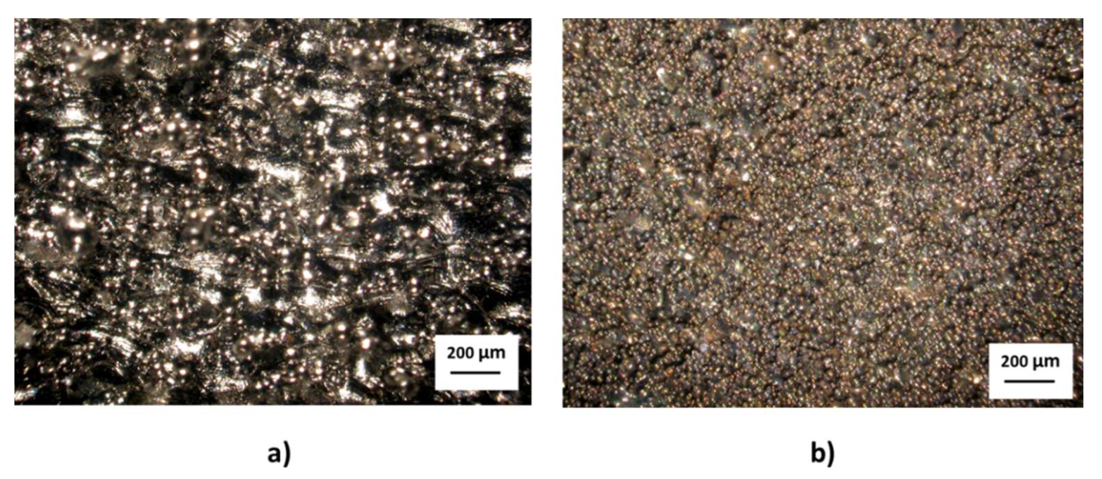
3.1. Metallographic Characterisation

The SEM micrograph of the Ti-6Al-4V Wr specimen, reported in Figure 2a, reveals a typical microstructure made up of a mixed α/β equiaxed phase structure. The DMLS process led to a martensitic microstructure, originating from the prior β grain boundaries (Figure 2b), while the EBM specimen (Figure 2c) shows a “α + β basketweave” microstructure, with the formation of α platelet colonies within the columnar grains.
It is known that the AM process affects the microstructure due to the different cooling rate, which is higher in the DMLS process than in EBM [30,31]. The DMLS process involves rapid heating and cooling, so that β↔α′ phase transformation is promoted. Indeed, the rapid cooling rate achieved during the DMLS process is higher than the critical cooling rate of 410 °C/s required for the martensitic transformation β↔α′ for Ti-6Al-4V [30,32]. Due to the complex thermal history involved during the process, generally, a subsequent heat treatment is applied to relieve the internal stresses. When a heat treatment was carried out at a temperature above the martensitic start temperature (650 °C for Ti-6Al-4V), followed by slow cooling in the furnace, the α′ martensitic phase was transformed into a fully lamellar α+β microstructure within the columnar prior β grain boundaries, highlighted in Figure 3. The heat treatment of the “as-produced” DMLS specimens was performed at 650 °C for 2 h, so that the α′ martensitic phase remained unchanged. During the EBM process, the build chamber generally was maintained at 650–700 °C, and after the process, the temperature decreased to room temperature [4,5]. The slow cooling resulted in the formation of α platelets in the centre of the grains, forming the classical Widmanstätten morphology [32,33].

3.2. Morphological Analysis

As reported earlier, an important drawback of AM technologies is the “poor” surface quality of the produced parts, due to the complex nature of the process [34]. In Figure 4, the surface appearance of both the “as-produced” EBM and DMLS manufactured specimens is shown. The difference between the specimens is clearly visible. The EBM specimen (Figure 4a) presents a complex texture, which is difficult to capture using an optical microscope, due to the presence of high peaks and deep valleys. It is characterised by a coarse particulate attached to the underlying melted surface, interrupted by clear electron beam scan tracks and wide and deep valleys or pores. The DMLS specimen (Figure 4b), instead, presents a finer texture than the EBM specimen. It exhibits a multi-directional particulate texture, interrupted by a few valleys and pores developed in random directions, and clear laser beam scan tracks. The Ti6Al4V Wr specimens presented a nearly mirror-like surface after the mechanical polishing [31], without features interesting for the scope of this paper; therefore, their pictures were omitted.
The SEM micrographs reported in Figure 5 confirm the observation inferred by the optical measurements and emphasise the differences between the samples, due to both the dimensions of the powders and the aforementioned effects. On both samples, it is possible to observe either unmelted or partially melted particles stuck on the fully fused ones. As expected, the powder particles are bigger on the as-produced EBM specimen, because the diameter of the powders used for producing the EBM specimens was between 45 and 105 µm. The scan tracks are even more evident than in the optical micrographs, and also, it is possible to detect the layer steps, which are higher than in the DMLS specimen. The latter, which was fabricated using powders with a diameter between 20 and 60 µm, shows numerous powder particles distributed very close to each other.
The complex profile created on the AM specimens is further highlighted in Figure 6, where optical micrographs of the samples’ sections are reported. The DMLS sample (Figure 6b) shows a profile characterised by a nearly uniform distribution of valleys and peaks. However, the EBM sample (Figure 6a) exhibits a jagged profile, in which various re-entrant features with irregular shapes can be observed [35], which, at some points, extend far inwards. It is easy to imagine that the presence of these re-entrant features, especially with their complex shape, could give rise to possible stagnation zones, triggering or quickening corrosion phenomena.
It is clear that the surface shape conferred by the two AM processes examined in this investigation may substantially vary depending on the building parameters. In addition, it is evident that other roughness parameters, such as the aerial roughness parameter (apart from the often-used Ra/Sa), are necessary to describe such surfaces.

3.3. Topography Analysis

The surface morphology analysis revealed the key topological differences conferred by the use of the two types of additive technologies, as depicted in Figure 7. The picture of the Ti-6Al-4V Wr specimen has not been reported for the aforementioned reasons. The morphology of the as-produced EBM surface is characterised by large partially melted particles arising from the solidified bulk material. The peaks appear to be uni-directionally oriented, and interrupted by deep and wide valleys. The as-produced DMLS specimen surface shows peaks made of solidified pools on which a significant number of unmelted or partially melted small particles are attached. The peaks are spaced out by moderately deep randomly distributed valleys.
Generally, to characterise the “roughness” of a surface, the average roughness parameter Ra, or its areal extension Sa, is considered. However, different morphologically structured surfaces can assume the same value of average roughness Ra, even if their topography is dissimilar, as discussed elsewhere [36]. Hence, to evaluate the complex topography obtained in AM parts, it is strongly recommended to consider other roughness parameters [37]. The characterisation of the surface shape, in the present work, was carried out by analysing four areal texture parameters (reported in Table 4): (i) the average roughness Sa; (ii) the root mean square height Sq; (iii) the Kurtosis parameter Sku, which relates the height distribution to a Gaussian distribution; and (iv) the skewness parameter Ssk, which provides an indication of the relative predominance of peaks or valleys. In addition, another parameter Sdr (the developed interfacial area ratio) is considered to estimate the extension of the “real” surface area contributed by the texture, as defined by the ISO 25178-2 and European Report EUR 15178N [38] standards.
As expected, the Ti-6Al-4V Wr sample shows a low value of Sa, while the Kurtosis parameter, Sku, suggests a Gaussian surface; the skewness parameter, Ssk, is positive; and the Sdr parameter highlights a relatively small increase in the developed surface area compared to the projected area. More interesting features were found by taking into consideration the additively manufactured specimens. The as-produced EBM specimen presents a Sa parameter that is approximately four-fold greater than that of the DMLS specimen (49.97 and 14.54 µm, respectively). Both specimens present sharp peaks, exhibiting values of the Sku parameter greater than 3 [39]. It is interesting to highlight that the surface distribution of “peaks and valleys”, too, depends on the formation technology used. The recorded skewness parameter, Ssk, in fact, shows a negative value (−0.49) for the as-produced DLMS specimen, while it assumes a positive value (0.11) for the as-produced EBM specimen. Skewness is a measure of the symmetry of the profile about the mean line with respect to which measurements are made. This indicates whether the spikes are predominantly negative or positive or if the surface profile has an even distribution of peaks and valleys. Therefore, it is possible to assume that the as-produced DLMS specimen surface is characterised by the presence of “more” valleys than the as-produced EBM specimen surface. In the same manner, considerable differences are found when comparing the estimated extension of the specimen surfaces. The Sdr parameter assumes the value of 551.50% for the as-produced EBM specimen, implying that the specimen surface area is approximately seven times greater than the geometric surface area. The increase in the as-produced DLMS specimen surface area is lower, but it means, roughly, that the specimen surface area is almost two times greater than the geometric surface area. Hence, as the specimen geometrical area is 2.8 cm2, using the Sdr value to estimate the extension of the area, the “actual” area of the Ti-6Al-4V Wr specimen has been estimated to be 3.5 cm2, whereas the as-produced EBM and the as-produced DMLS specimens have been estimated to possess an “actual” area equal to 18.43 and 5.44 cm2, respectively.

3.4. Crystallographic Analysis

XRD diffractograms obtained on “as-produced” specimens are reported in Figure 8 in comparison to the pattern of the traditionally produced component. The Ti-6Al-4V Wr specimen presents hexagonal peaks that are characteristic of the Ti hexagonal close-packed (hcp) structure, generally defined as α phase (black diamond), and only one peak related to the β phase (orange circle). The EBM specimen presents the same peaks as the Ti-6Al-4V wrought specimen, but the peaks are weaker, shorter, and broader. The presence of titanium oxides is observed in the DMLS specimens. In particular, the TiO2 (green square) detected on the DMLS specimens is in the rutile form. It is produced due to the heat treatment carried out at 650 °C for 2 h under an Argon gas atmosphere to reduce internal stresses. The lack of the β phase peak in the AM specimens could indicate a martensitic microstructure for the as-produced DMLS specimens, or a wide presence of α phase, for the as-produced EBM.

3.5. Electrochemical Test

When a new material or new process is proposed for biomedical applications, the part surface characteristics are vital for proving the possibility of its use in the human body, and among them, the corrosion resistance plays a crucial role. As reported earlier, surprisingly, even though the AM technologies are rapidly spreading and several research efforts have addressed the electrochemical characterisation of their bulk properties, few studies have considered the electrochemical properties of the “as-produced” parts.
This aspect is significant for exploiting the peculiarities of the topography of “as-produced” AM parts, to increase the osseointegration rate in bio-devices and, simultaneously, the amount of bio-device/tissue adhesion by taking advantage of mechanical interlocking.
The experimental approach used in this work was the testing of the specimens using the potentiodynamic polarisation technique in in vitro conditions, recorded during immersion in Hank’s solution. The results obtained are reported in Figure 9.
The benchmark specimen Ti-6Al-4V Wr (Figure 9a, black curve) presents the well-known behaviour exhibited by the alloy when immersed in Hank’s solution, showing a large and steady range of passivity (from −0.200 V to 2.5 V vs. SCE), low passive current density ip (1 × 10⁻⁶ A/cm2), corrosion potential Ecorr = −0.480 V vs. SCE, and a pitting potential of approximately 2.5 V vs. SCE, in accordance with the literature [9]. The shape of the polarisation curves obtained for the AM specimens is significantly different from the curve for the Ti-6Al-4V specimen. Their corrosion potential is higher than that of the wrought specimen and similar to each other. In addition, it may be noted that both the polarisation curves of the as-produced AM specimens present a similar trend, showing a pseudo-passivity current of approximately 3 × 10⁻⁶ A/cm2. The current density also remains constant for values of about 1 × 10⁻⁴ A/cm2, even if the as-produced EBM specimen shows high scattering. This observation is noteworthy as it shows that, although the two specimens were obtained using different experimental conditions, the interface reactions are of the same type, thus determining currents of the same order of magnitude in similar potential intervals. The extension of the latter, however, as well as the scattering present in the data of the as-produced EBM specimens, can be correlated to the topographies of the two surfaces, which, as previously shown, are significantly different from each other. In particular, the deep valleys (see Figure 6a and Figure 7a) shown by the as-produced EBM specimen determine the presence of zones in which the interface processes are significantly more active. A confirmation of the interpretation of the experimental data is provided in the work of Burstein [40], who found a relationship between the roughness of a passive 304 stainless steel and the number of transients caused by the presence of metastable pits. In the same manner, the trans-passivity potential detected at 1.3 V vs. SCE could be due to the surface shape [41].
In Figure 9a, the data are shown considering the geometrical area of the specimens. It is clearly observable that the recorded current for the AM specimens are higher than that exhibited by the Ti-6Al-4V Wr specimen across the whole range of considered potentials. However, as shown in Figure 9b, the scenario changes if the “estimated real surface area” of the specimens is considered. In fact, due to the results obtained from the topographic characterisation of the specimens and shown in Table 4, a shift to lower current density of all the potentiodynamic curves is recorded. The curve of the Ti-6Al-4V Wr specimen is almost unchanged, due to the small variation in its actual area, whereas the shift of the two curves of the AM-produced specimens determines a substantial difference in the current densities. Hence, the pseudo-passivity current shown by the as-produced EBM specimen, measured in the range 0.8–1.2 V vs. SCE, can be estimated to be 4 × 10⁻⁷ A/cm2. This value is approximately an order of magnitude lower than the data reported in the Figure 9a. The shift presented by the as-produced DMLS current curve is lower due to the reduced increase in the “actual area” obtained through the specimen topography analysis. This aspect, in our opinion, remains unclear and needs further in-depth analysis, to determine the true corrosion resistance of AM-produced parts.
In conclusion, the presence of the spikes at approximately 1 V vs. SCE and after 1.5 V vs. SCE, recorded for the “as-produced” EBM specimens, suggests that the titanium oxide formed on the EBM specimens is more unstable than that on the DMLS specimens. The instability of the EBM specimens can be related to their jagged (or indented) roughness profile (see Figure 6a). However, the as-produced DMLS specimens present higher current density values and also a wrinkled surface profile (see Figure 6b), and the polarisation curve is more stable. Both the as-produced DMLS and EBM specimens show a positive Ecorr, but a real and wide range of passivity, comparable to the Ti-6Al-4V Wr specimen, is missing.
Electrochemical investigations performed on the mechanically polished specimens revealed important differences, as depicted in Figure 10, if compared to the data reported previously.
The AM specimens present corrosion potential that is slightly negative compared to the that of the Ti-6Al-4V Wr specimen, as pictured in Figure 10a. The passive current density until 1.5 V vs. SCE has the same value as that shown by the Ti-6Al-4V specimen (approximately 1 × 10⁻⁶ A/cm2) for both EBM-MP and DMLS-MP specimens. Above this potential value, the potentiodynamic polarisation curves of both the AM specimens present a “transition current zone”, correlated with the oxygen evolution reaction [11,14,42]. In particular, the DMLS-MP specimens show a negligible transition current zone, in which the current density increases and decreases until 1.8 V vs. SCE. However, the EBM-MP specimens show a more pronounced transition current zone, suggesting a higher instability of the oxide layer formed on this specimen. Some authors have observed a rapid increase in current density above 1.3 V vs. SCE, which can be interpreted as the transpassivity potential value [10]. By increasing the range of potential values, it is possible to see that the increase in current density is limited to a narrow range of potentials, as confirmed by Chiu et al. (2018) [14]. It is possible to assume that the estimated “actual” area of the mechanically polished additively manufactured specimen is comparable to that of the traditionally produced one, since both were polished and stored in the same manner. As a result, the potentiodynamic polarisation curves of the mechanically polished specimens related to the “actual area” present a shift towards lower current density values, which is so small that it does not have a significant effect on the passive current density ip, as depicted in Figure 10b.
For clarity, the corrosion parameters of the potentiodynamic polarisation analysis are reported in Table 5.
The potentiodynamic polarisation results clearly highlight the influence and, therefore, the importance of the surface morphology.

4. Conclusions

The effects of surface characteristics on the morphological and corrosion resistance of a titanium alloy, Ti-6Al-4V, fabricated by DMLS and EBM processes for biomedical applications were investigated. The microstructural analysis showed the expected martensitic or basket-wave structures for the AM specimens. XRD revealed the presence of titanium dioxide on the DMLS specimen due to the heat treatment carried out to relieve internal stresses. The topographical analysis allowed the estimation of the actual area extension of the AM specimens. Potentiodynamic polarisation tests carried out on the as-produced AM specimens revealed a significantly different electrochemical behaviour when compared to that revealed for the traditionally produced specimen, showing the presence of a pseudo-passivity range and higher current density in almost all the investigated potential ranges. Attention was focused on considering the “actual surface extension” and evaluating the corrosion resistance of the specimens. However, the electrochemical behaviour of the mechanically polished specimens is similar to that of Ti-6Al-4V Wr, even if an instability zone is exhibited by the AM specimens. In wider terms, the results showed that further studies are needed to comprehend the true electrochemical behaviour and corrosion resistance of AM-produced parts. In addition, to allow their safe use in biomedical applications, both in the case of as-produced devices and of those in which the outermost layer has been removed, an ad-hoc surface treatment process is required.

Author Contributions

T.M., conceptualization, supervision, writing—review and editing, and resources; A.A., methodology, validation, investigation, and writing—original draft. All authors have read and agreed to the published version of the manuscript.

Funding

This research received no external funding.

Acknowledgments

The authors are grateful to Ing. Paolo Bariani, Schaefer South-East Europe s.r.l., for assistance with the roughness measurements.

Conflicts of Interest

The authors have no conflict of interest to declare.

References

  1. Andani, M.T.; Moghaddam, N.S.; Haberland, C.; Dean, D.; Miller, M.J.; Elahinia, M. Metals for bone implants. Part 1. Powder metallurgy and implant rendering. Acta Biomater. 2014, 10, 4058–4070. [Google Scholar] [CrossRef] [PubMed]
  2. Over, C.; Meiners, W.; Wissenbach, K.; Lindemann, M.; Hutfless, J. Selective Laser melting: A new approach for the direct manufacturing of metal parts and tools. In Proceedings of the Euro-uRapid-, Nuremberg, Germany, 2001; pp. 391–398. [Google Scholar]
  3. Gockel, J.; Sheridan, L.; Koerper, B.; Whip, B. The influence of additive manufacturing processing parameters on surface roughness and fatigue life. Int. J. Fatigue 2019, 124, 380–388. [Google Scholar] [CrossRef]
  4. Koike, M.; Greer, P.; Owen, K.; Lilly, G.; Murr, L.E.; Gaytan, S.M.; Martinez, E.; Okabe, T. Evaluation of Titanium Alloys Fabricated Using Rapid Prototyping Technologies-Electron Beam Melting and Laser Beam Melting. Materials 2011, 4, 1776–1792. [Google Scholar] [CrossRef]
  5. Rafi, H.K.; Karthik, N.V.; Gong, H.; Starr, T.L.; Stucker, B.E. Microstructures and Mechanical Properties of Ti6Al4V Parts Fabricated by Selective Laser Melting and Electron Beam Melting. J. Mater. Eng. Perform. 2013, 22, 3872–3883. [Google Scholar] [CrossRef]
  6. Shunmugavel, M.; Polishetty, A.; Littlefair, G. Microstructure and Mechanical Properties of Wrought and Additive Manufactured Ti-6Al-4V Cylindrical Bars. Procedia Technol. 2015, 20, 231–236. [Google Scholar] [CrossRef] [Green Version]
  7. Tan, X.; Kok, Y.; Tan, Y.J.; Descoins, M.; Mangelinck, D.; Tor, S.B.; Leong, K.F.; Chua, C.K. Graded microstructure and mechanical properties of additive manufactured Ti–6Al–4V via electron beam melting. Acta Mater. 2015, 97, 1–16. [Google Scholar] [CrossRef]
  8. Zhang, L.-C.; Attar, H. Selective Laser Melting of Titanium Alloys and Titanium Matrix Composites for Biomedical Applications: A Review. Adv. Eng. Mater. 2016, 18, 463–475. [Google Scholar] [CrossRef]
  9. Leon, A.; Levy, G.K.; Ron, T.; Shirizly, A.; Aghion, E. The effect of strain rate on stress corrosion performance of Ti6Al4V alloy produced by additive manufacturing process. J. Mater. Res. Technol. 2020, 9, 4097–4105. [Google Scholar] [CrossRef]
  10. Leon, A.; Levy, G.K.; Ron, T.; Shirizly, A.; Aghion, E. The effect of hot isostatic pressure on the corrosion performance of Ti-6Al-4 V produced by an electron-beam melting additive manufacturing process. Addit. Manuf. 2020, 33, 101039. [Google Scholar] [CrossRef]
  11. de Damborenea, J.J.; Arenas, M.A.; Larosa, M.A.; Jardini, A.L.; Zavaglia, C.A.d.; Conde, A. Corrosion of Ti6Al4V pins produced by direct metal laser sintering. Appl. Surf. Sci. 2017, 393, 340–347. [Google Scholar] [CrossRef]
  12. Bai, Y.; Gai, X.; Li, S.; Zhang, L.-C.; Liu, Y.; Hao, Y.; Zhang, X.; Yang, R.; Gao, Y. Improved corrosion behaviour of electron beam melted Ti-6Al–4V alloy in phosphate buffered saline. Corros. Sci. 2017, 123, 289–296. [Google Scholar] [CrossRef]
  13. Gai, X.; Bai, Y.; Li, J.; Li, S.; Hou, W.; Hao, Y.; Zhang, X.; Yang, R.; Misra, R.D.K. Electrochemical behaviour of passive film formed on the surface of Ti-6Al-4V alloys fabricated by electron beam melting. Corros. Sci. 2018, 145, 80–89. [Google Scholar]
  14. Chiu, T.-M.; Mahmoudi, M.; Dai, W.; Elwany, A.; Liang, H.; Castaneda, H. Corrosion assessment of Ti-6Al-4V fabricated using laser powder-bed fusion additive manufacturing. Electrochim. Acta 2018, 279, 143–151. [Google Scholar] [CrossRef]
  15. Dai, N.; Zhang, J.; Chen, Y.; Zhang, L.-C. Heat Treatment Degrading the Corrosion Resistance of Selective Laser Melted Ti-6Al-4V Alloy. J. Electrochem. Soc. 2017, 164, C428–C434. [Google Scholar] [CrossRef]
  16. Zhao, B.; Wang, H.; Qiao, N.; Wang, C.; Hu, M. Corrosion resistance characteristics of a Ti-6Al-4V alloy scaffold that is fabricated by electron beam melting and selective laser melting for implantation in vivo. Mater. Sci. Eng. C 2017, 70, 832–841. [Google Scholar] [CrossRef]
  17. Kaji, F.; Barari, A. Evaluation of the Surface Roughness of Additive Manufacturing Parts Based on the Modelling of Cusp Geometry. IFAC-PapersOnLine 2015, 48, 658–663. [Google Scholar] [CrossRef]
  18. Strano, G.; Hao, L.; Everson, R.M.; Evans, K.E. Surface roughness analysis, modelling and prediction in selective laser melting. J. Mater. Process. Technol. 2013, 213, 589–597. [Google Scholar] [CrossRef]
  19. Razavi, S.M.J.; van Hooreweder, B.; Berto, F. Effect of build thickness and geometry on quasi-static and fatigue behavior of Ti-6Al-4V produced by Electron Beam Melting. Addit. Manuf. 2020, 36, 101426. [Google Scholar] [CrossRef]
  20. Tang, H.P.; Zhao, P.; Xiang, C.S.; Liu, N.; Jia, L. 3.3—Ti-6Al-4V orthopedic implants made by selective electron beam melting. In Titanium in Medical and Dental Applications; Froes, F.H., Qian, M., Eds.; Woodhead Publishing: Cambridge, UK, 2018; pp. 239–249. [Google Scholar]
  21. Curtis, A.S.; Wilkinson, C.D. Reactions of cells to topography. J. Biomater. Sci. Polym. Ed. 1998, 9, 1313–1329. [Google Scholar] [CrossRef] [PubMed]
  22. Deligianni, D.D.; Katsala, N.; Ladas, S.; Sotiropoulou, D.; Amedee, J.; Missirlis, Y.F. Effect of surface roughness of the titanium alloy Ti–6Al–4V on human bone marrow cell response and on protein adsorption. Biomaterials 2001, 22, 1241–1251. [Google Scholar] [CrossRef]
  23. Thomsen, P.; Malmstrom, J.; Emanuelsson, L.; Rene, M.; Snis, A. Electron beam-melted, free-form-fabricated titanium alloy implants: Material surface characterization and early bone response in rabbits. J. Biomed. Mater. Res. Part B Appl. Biomater. 2009, 90, 35–44. [Google Scholar] [CrossRef] [PubMed]
  24. Ruppert, D.S.; Harrysson, O.L.A.; Marcellin-Little, D.J.; Abumoussa, S.; Dahners, L.E.; Weinhold, P.S. Osseointegration of Coarse and Fine Textured Implants Manufactured by Electron Beam Melting and Direct Metal Laser Sintering. 3D Print. Addit. Manuf. 2017, 4, 91–97. [Google Scholar] [CrossRef] [PubMed]
  25. Standard ISO 4287:1997. Geometric Product Specifications (GPS)—Surface Texture: Profile Method -Terms, Definitions and Surface Texture Parameters; International Organization for Standardization: Geneva, Switzerland, 1997. [Google Scholar]
  26. Standard ISO 25178-2:2012. Geometrical Product Specifications (GPS)—Surface Texture: Areal Part 2: Terms, Definitions and Surface Texture Parameters. Available online: https://www.iso.org/obp/ui/#iso:std:iso:25178:-2:ed-1:v1:en (accessed on 28 July 2020).
  27. Standard ISO17475:2005. Corrosion of Metals and Alloys—Electrochemical Test Methods—Guidelines for Conducting Potentiostatic and Potentiodynamic Polarization Measurements, 1st ed.; Multiple. Distributed through American National Standards Institute (ANSI): New York, NY, USA, 2007; pp. 1–24. [Google Scholar]
  28. Acquesta, A.; Carangelo, A.; Monetta, T. TiO2 Nanotubes on ti dental implant. Part 3: Electrochemical behavior in hank’s solution of titania nanotubes formed in ethylene glycol. Metals 2018, 8, 489. [Google Scholar] [CrossRef] [Green Version]
  29. Monetta, T.; Acquesta, A.; Carangelo, A.; Bellucci, F. TiO2 nanotubes on Ti dental implant. Part 2: EIS characterization in Hank’s solution. Metals 2017, 7, 220. [Google Scholar] [CrossRef] [Green Version]
  30. Murr, L.E.; Gaytan, S.M.; Ramirez, D.A.; Martinez, E.; Hernandez, J.; Amato, K.N.; Shindo, P.W.; Medina, F.R.; Wicker, R.B. Metal Fabrication by Additive Manufacturing Using Laser and Electron Beam Melting Technologies. J. Mater. Sci. Technol. 2012, 28, 1–14. [Google Scholar] [CrossRef]
  31. Hatamleh, M.M.; Wu, X.; Alnazzawi, A.; Watson, J.; Watts, D. Surface characteristics and biocompatibility of cranioplasty titanium implants following different surface treatments. Dent. Mater. 2018, 34, 676–683. [Google Scholar] [CrossRef] [Green Version]
  32. Ahmed, T.; Rack, H.J. Phase transformations during cooling in α+β titanium alloys. Mater. Sci. Eng. A 1998, 243, 206–211. [Google Scholar] [CrossRef]
  33. L.E. Murr, S.A.; Quinones, S.M.; Gaytan, M.I.; Lopez, A.; Rodela, E.Y.; Martinez, D.H.; Hernandez, E.; Martinez, F.; Medina, R.B. Wicker, Microstructure and mechanical behavior of Ti–6Al–4V produced by rapid-layer manufacturing, for biomedical applications. J. Mech. Behav. Biomed. Mater. 2009, 2, 20–32. [Google Scholar] [CrossRef]
  34. Calignano, F.; Manfredi, D.; Ambrosio, E.P.; Iuliano, L.; Fino, P. Influence of process parameters on surface roughness of aluminum parts produced by DMLS. Int. J. Adv. Manuf. Technol. 2013, 67, 2743–2751. [Google Scholar] [CrossRef] [Green Version]
  35. Triantaphyllou, A.; Giusca, C.; Macaulay, G.; Roerig, F.; Hoebel, M.; Leach, R.; Tomita, B.; Milne, K. Surface texture measurement for additive manufacturing. Surf. Topogr. Metrol. Prop. 2015, 3, 024002. [Google Scholar] [CrossRef]
  36. Monetta, T.; Acquesta, A.; Bellucci, F. Evaluation of roughness and electrochemical behavior of titanium in biological environment. Metall. Ital. 2014, 106, 13–21. [Google Scholar]
  37. Monetta, T.; Acquesta, A.; Bellucci, F. A multifactor approach to evaluate the sealing of ‘smooth-wall’ containers for food packaging. Surf. Coat. Technol. 2017, 310, 33–37. [Google Scholar] [CrossRef]
  38. Stout, K.J.; Blunt, L.; Dong, W.P.; Mainsah, E.; Luo, N.; Mathia, T.; Sullivan, P.J.; Zahouani, H. Development of Methods for Characterisation of Roughness in Three Dimensions; Elsevier Science: Amsterdam, The Netherlands, 2000. [Google Scholar]
  39. Gadelmawla, E.S.; Koura, M.M.; Maksoud, T.M.A.; Elewa, I.M.; Soliman, H.H. Roughness parameters. J. Mater. Process. Technol. 2002, 123, 133–145. [Google Scholar] [CrossRef]
  40. Burstein, G.T.; Pistorius, P.C. Surface Roughness and the Metastable Pitting of Stainless Steel in Chloride Solutions. Corrosion 1995, 51, 380–385. [Google Scholar] [CrossRef]
  41. Cai, Z.; Shafer, T.; Watanabe, I.; Nunn, M.E.; Okabe, T. Electrochemical characterization of cast titanium alloys. Biomaterials 2003, 24, 213–218. [Google Scholar] [CrossRef]
  42. de Damborenea, J.J.; Larosa, M.A.; Arenas, M.A.; Hernández-López, J.M.; Jardini, A.L.; Ierardi, M.C.F.; Zavaglia, C.A.C.; Filho, R.M.; Conde, A. Functionalization of Ti6Al4V scaffolds produced by direct metal laser for biomedical applications. Mater. Des. 2015, 83, 6–13. [Google Scholar] [CrossRef]
Figure 1. Reference system assigned to the specimens to conduct the analysis of the microstructure.
Metals 10 01015 g001
Figure 2. SEM observations in the XZ plane of (a) Ti-6Al-4V Wr, (b) EBM-MP and (c) DMLS-MP specimens.
Metals 10 01015 g002
Figure 3. Optical pictures captured along the building directions for (a) EBM-MP and (b) DMLS-MP samples.
Metals 10 01015 g003
Figure 4. Surface appearance of the “as-produced” additive manufacturing (AM) specimens obtained by optical microscopy: (a) EBM and (b) DMLS.
Metals 10 01015 g004
Figure 5. The surface appearance of the as-produced EBM (on top) and the as-produced DMLS (on bottom) specimens.
Metals 10 01015 g005
Figure 6. Morphological profile of (a) as-produced EBM and (b) as-produced DMLS samples.
Metals 10 01015 g006
Figure 7. 3D topography of (a) as-produced EBM and (b) as-produced DMLS specimens (arrows indicate the building direction).
Metals 10 01015 g007
Figure 8. XRD spectrum of Ti-6Al-4V Wr (black line), as-produced EBM (blue line) and as-produced DMLS (red line) specimens.
Metals 10 01015 g008
Figure 9. (a) Potentiodynamic polarisation curves obtained by considering the geometrical areas of the as-produced EBM (blue curve) and as-produced DMLS (red curve) specimens, compared to the Ti-6Al-4V Wr specimen (black curve); (b) Potentiodynamic polarisation curves obtained by considering the estimated surface area by means of topographical measurements.
Metals 10 01015 g009
Figure 10. (a) Potentiodynamic polarisation curves obtained by considering the geometrical area of the EBM-MP (blue curve) and DMLS-MP (red curve) specimens, compared to the Ti-6Al-4V Wr specimen (black curve); (b) Potentiodynamic polarisation curves obtained by considering the estimated surface area by means of topographical measurements.
Metals 10 01015 g010
Table 1. Parameters used in the direct metal laser sintering (DMLS) and electron beam melting (EBM) processes.
ParametersEOS M280 (DMLS)ARCAM Q20 (EBM)
Power170 W-
Voltage-60 kV
Min. Beam size100 µm180 µm
Environment ArgonVacuum
Layer thickness30 µm90 µm
Scan speed1250 mm/s1500 mm/s
Hatching distance100 µm100 µm
Table 2. Chemical composition of Ti-6Al-4V powders used in the EBM and DMLS processes.
TechnologiesAluminium (Al)Vanadium (V)Iron (Fe)Oxygen (O)Nitrogen (N)Hydrogen (H)Carbon (C)Titanium (Ti)
EBM
Arcam Q20
Ti-6Al-4V
6.35%3.98%0.18%0.13%0.01%0.002%0.02%Balance
DMLS
EOS M280
Ti-6Al-4V
6.02%3.82%0.17%0.11%0.01%<0.0019%0.01%Balance
Table 3. Acronyms used to identify the specimens.
SetSpecimenAcronym
SurfaceTi-6Al-4V produced by EBM technology and characterised as producedas-produced EBM
Ti-6Al-4V produced by DMLS technology, heat treated, and characterised as-producedas-produced DMLS
BulkTi-6Al-4V produced by EBM technology, mechanically polished, and stored in airEBM-MP
Ti-6Al-4V produced by DMLS technology, mechanically polished, and stored in airDMLS-MP
BenchmarkTi-6Al-4V rolled, mechanically polished, and stored in airTi-6Al-4V Wr
Table 4. Roughness parameters of the Ti-6Al-4V Wr, as-produced EBM, and as-produced DMLS specimens.
Roughness ParametersTi6Al4V WrAs-Produced EBMAs-Produced DMLS
Sa (µm)0.6249.9714.54
Sq (µm)0.7963.4518.54
Sku3.694.075.57
Ssk0.120.11−0.49
Sdr22.79%551.50%92.50%
Table 5. Summary of corrosion parameters of the potentiodynamic polarisation analysis.
SpecimenEcorr
(mV vs. SCE)
Ep
(mV vs. SCE)
ip
Geom. Area
(µA/cm2)
ip
Real Area
(µA/cm2)
Ti-6Al-4V Wr−0.480−0.20010.8
as-produced EBM0.0400.7502.50.4
as-produced DMLS0.0030.3002.52.4
EBM-MP−0.490−0.20010.8
DMLS-MP−0.505−0.25010.8

