Article

Empirical Models for Surface Roughness and Topography in 5-Axis Milling Based on Analysis of Lead Angle and Curvature Radius of Sculptured Surfaces

Department of Manufacturing Techniques and Automation, The Rzeszow University of Technology, 35-959 Rzeszów, Poland
Metals 2020, 10(7), 932; https://doi.org/10.3390/met10070932
Submission received: 25 June 2020 / Revised: 5 July 2020 / Accepted: 9 July 2020 / Published: 10 July 2020

Abstract

:
The orientation of the tool axis and the variable curvature of the machined profile of a sculptured surface have a significant impact on the roughness and topography of the surface in the process of 5-axis milling by means of a toroidal milling cutter. The selection of the orientation of the toroidal milling cutter axis relative to the radius of curvature of the machined surface profile is very important as it can provide a better surface quality and an even distribution of roughness parameters. In this paper, an attempt to carry out model tests to obtain mathematical relationships was made. These relationships were to determine the impact of the tool axis orientation and the variable curvature radius of the machined profile on the surface roughness and its topography in the 5-axis milling process of sculptured surfaces. The tests were conducted on an example of a turbine blade made of Inconel 718 alloy. A measurable effect of the work undertaken was the development of model relationships that can be applied in specialized modules of CAM (Computer Aided Manufacturing) systems supporting the programming of 5-axis machining of sculptured surfaces. The models developed will also make it possible to obtain an evenly distributed roughness on the machined sculptured surface, especially on the surface of the turbine blades of the Inconel 718 alloy, as indicated by the results of the tests carried out.

1. Introduction

Sculptured surfaces are currently widely used for the design of complex elements, mainly turbine blades, especially in the aviation and energy industries. The surfaces in these types of elements are characterized by a variable radius of a curved line contour along the machined profile. Due to the complexity of the shape of these surfaces, 5-axis milling is used for their machining.
The 5-axis trajectory of the tool movement is generated in a CAM (Computer Aided Manufacturing) system, which offers different algorithms of the tool positioning and the machining strategies, depending on the geometry of the surface to be treated. One of the main adjustable parameters of 5-axis milling is the lead and tilt angle. The above considerations are shown schematically in Figure 1.
In [1], the authors stated that the machined surface quality resulted from the choice of the strategy and the corresponding cutting parameters. According to this statement, they developed a predicting model of the surface roughness of the sculptured surface after 5-axis milling. However, the researchers did not include the variable radius of the surface profile curvature and different lead angle values in the studies, and used a toroidal cutter for the research. When analyzing the results obtained by them, it can be stated that the roughness of the curvilinear surface after 5-axis milling was characterized by an uneven distribution of roughness parameters. This may be due to the variable curvature radius along the surface profile being machined. Similar conclusions were obtained after analyzing the results of the research shown in [2]. Uneven distribution of roughness parameters, especially on the surfaces of turbine blades, resulted in a decrease in the efficiency of the rotor machine. Particular attention was paid to this in [3], which is shown in Figure 2, according to the study [3].
The first attempts of fundamental research in the field of uneven distribution of the roughness parameters were undertaken in [4,5]. Cao et al. [4] attempted to determine the effect of the curvature radius of a sculptured surface on the selection of the 5-axis tool path whereas Yao et al. [5] tried to determine the impact of tool orientation and surface curvature on the surface integrity in TC17 alloy milling with a ball end milling cutter. In both of these works, there were a lot of cognitive data, but there were no models linking the geometrical parameters of the surface with the kinematic parameters of the 5-axis milling process. Such an attempt, as the first to date, will be made in this work.
Various studies on the influences of tool axis orientation on the surface roughness and topography during 5-axis milling of sculptured surfaces were conducted. Toh in his work [6] focused on the 5-axis high-speed milling and reported that the minimum surface roughness was obtained when a positive lead angle was used. Chen et al. in [7,8] made an attempt to investigate the 5-axis milling theory and revealed the effects of various tool orientations on the surface roughness. In turn, Ko et al. [9] focused on the lead and tilt angle and cutter path by considering, among others, the surface roughness in their research where the results indicated that a 15° inclination angle was optimal. The work of Cao et al. [4] attempted to investigate the effect of the radius of curvature of sculptured surfaces on tool path selection in 3-axis milling. For the tool path selection, the method of constant scallop height based on high productivity was used. Kalvoda et al. [10] indicated that they obtained the best surface roughness when the lead and tilt angles were negative, and the worst surface roughness was when there was no inclination. Lim et al. [2] paid attention to the high-speed finish machining of sculptured surfaces of a blade and investigated the effects of four different cutter path orientations on the surface roughness and surface morphology. The results of their research indicated that the distribution of roughness parameters was uneven. Hendriko [11] developed a model to calculate the scallop height of a toroidal cutter in 5-axis milling. His research shed new light on the problem of roughness in 5-axis milling, but also showed no correlation between kinematic and geometric parameters, which was similar in the work of Segonds et al. [12].
A sculptured curvilinear surface is usually composed of many curved surface patches with different curvatures/radii of curvature. As these surfaces are widely used in various fields, the 5-axis milling process has stringent requirements to obtain a high accurate shape and the required surface roughness and topography. The lead angle of the tool axis changes during the sculptured surface milling process due to changes in the surface normal vector, thus affecting the surface quality.
In machining a sculptured surface, recent studies have mainly focused on the cutter path generation method with tool axis orientation for a curved surface [13,14] and the engagement of a tool and machining surface [15]. However, these studies did not consider the variable radii of the curvature of the machined surface, which could result in being able to use the processing experience or the test results to evaluate the sculptured surface machining strategies or tool axis orientation in the actual machining.
Various studies on the surface roughness and topography during 5-axis milling of sculptured surfaces that considered different cutter path orientations and tool axis orientation were conducted. In [16], the researchers described the generation of cutter paths, the identification and effects of tool orientations on the milling process, and the selection of tool parameters. They discussed the problems that occurred during sculptured surface (especially curvilinear) machining and future research directions. Xie et al. [17] proposed a curvature distribution value to evaluate the 5-axis machining efficiency and machining accuracy, and verified the validity by conducting experiments and analyses. This proposal may also apply to the assessment of surface quality in the 5-axis machining of sculptured surfaces. Duan et al. [18] analyzed the tool orientation when 5-axis machining 300M steel and summarized the surface roughness after machining planes with different angles. Cao et al. [4] analyzed the effect of the curvature radius of the sculptured surface on finish 5-axis milling tool path selection. They stated that curvature radius, especially the normal curvature radius that is parallel to the feeding direction, had an obvious effect on machining productivity and quality.
In conclusion, one of the groups of research has focused on the influences of tool axis orientation on surface roughness and topography in a 5-axis milling process of sculptured surfaces and have obtained numerous research findings from the perspective of theory and experimentation. In the case of the radii of the curvature of sculptured surfaces, which are used for profiling turbine blades, Cao et al. [4] investigated the effect of the curvature radius of the sculptured surface on finish milling tool path selection, and Yao et al. [5] and Yang et al. [19] studied the effects of tool orientation and surface curvature on surface integrity in ball end milling. However, their studies did not bind the lead angle with the radius of curvature to the mathematical model, and did not determine their effect on the surface roughness and topography. In this paper, the effects of lead angle and radii of curvature on surface roughness and topography during the 5-axis milling of Inconell 718 nickel alloy using the toroidal cutter were studied, and different forms of surface structures were taken based on the turbine blade. The results can provide new guidance for the 5-axis machining of sculptured surface parts of Inconel 718 nickel alloy to obtain good surface roughness and topography.

2. Five-Axis Milling Process of Sculptured Surfaces

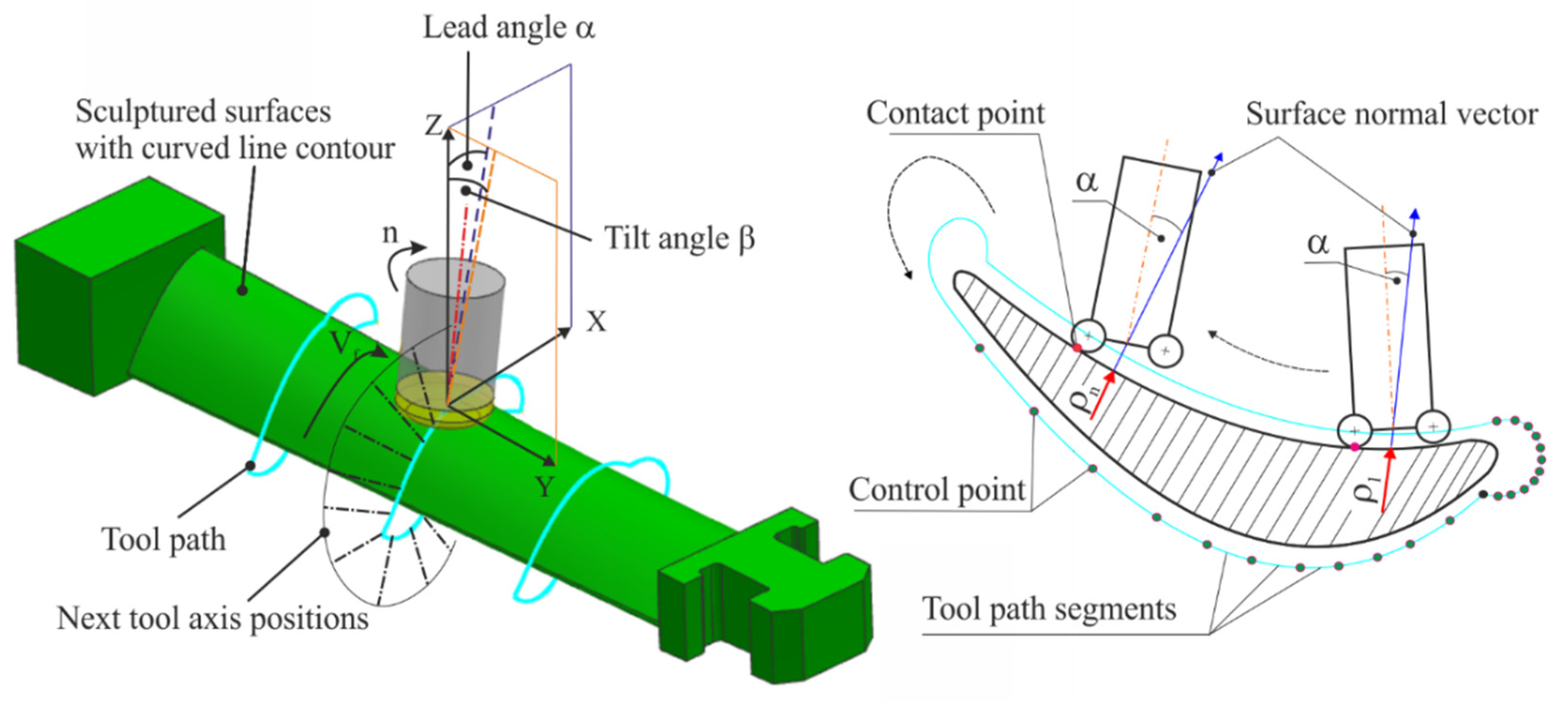
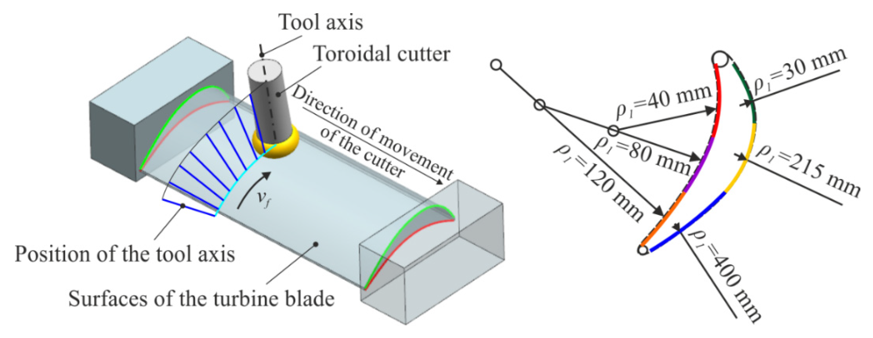
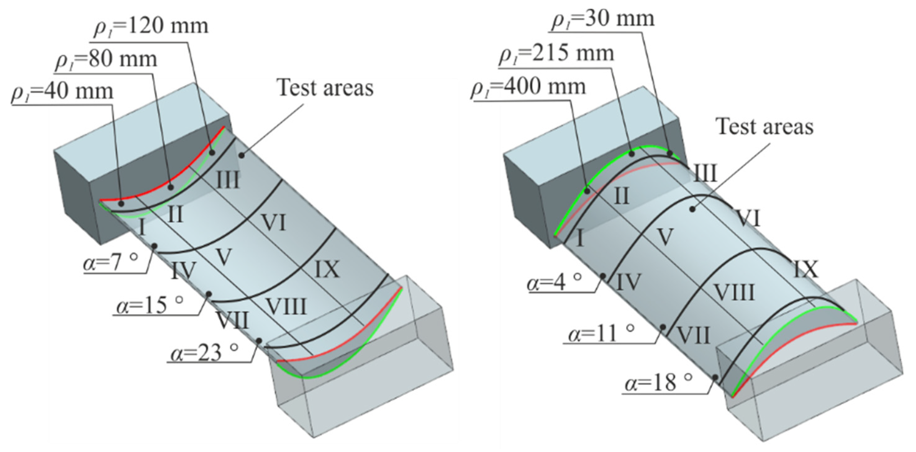
2.1. Definition of Tool Axis Orientation and Experimental Model of Sculptured Surfaces with Variable Radii of Curvature

A toroidal cutter is increasingly used to manufacture sculptured surfaces, and there are various possible tool axis orientations while maintaining maximum performance and good surface roughness due to its geometrical features. The lead angle and the tilt angle are often used to describe the tool axis orientation during the real CAM/CNC (Computerized Numerical Control) programming and post-processing. This paper adopted the lead angle to describe the tool axis orientation for the convenience of description and analysis. Figure 3a presents the analytical diagram of the tool axis orientation, and the relationship between the existing sets of angles is as follows:
α = arcsin ( sin ( θ ) · cos ( ζ ) sin ( θ ) 2 · cos ( ζ ) 2 + cos ( θ ) 2 )
β = arccos ( sin ( θ ) 2 · cos ( ζ ) 2 + cos ( θ ) 2 )
where α is the lead angle; β is the tilt angle; θ is the inclination angle; and ζ is the rotational angle.
Variation in the lead angle can have a significant effect on the toroidal cutter contact point position; a schematic view is shown in Figure 3b. Parameter rp represents the radius of the round cutting insert of the toroidal milling cutter, α denotes the lead angle, ap is the cutting depth, and γ is the normal angle between the toroidal cutter contact point boundary (E) and the cutting plane point (F). The value of γ can be calculated by solving Equation (3):
γ = arccos ( r p a p r p )
It can clearly be seen that the point with the highest cutting speed (vc) is clockwise to the side edge of the toroidal milling cutter. When analyzing geometrical relationships, the following conclusions can be obtained: at any point on the cutting edge, the cutting speed is always greater than 0 (vc > 0) and the tool center does not participate in the milling process; when the material is on the left side of the round cutting insert, the maximum cutting speed vcE = vcmax∙sin(α + η) (point E); when the material is on the right side of the round cutting insert, the minimum cutting speed vcG = vcmax∙sin(αη) (point G); and the cutting speed of the maximum cutting depth vcF = vcmax∙sinα (point F). The effective radius of the toroidal milling cutter passes through point F, which can be calculated from Equation (4):
R e f f = R T r p ( 1 sin ( α ) )
Sculptured surfaces can be divided into convex, concave, biconvex, and biconcave surfaces according to their characteristic parameters in the form of curvatures/radii of curvature. The turbine blade surface consists of the suction surface (convex), the pressure surface (concave), and the leading and trailing edge surfaces. To simulate features such as the suction surface and the pressure surface, their geometry is based on different radii of curvature, which show continuous variability of value in the direction of the tool feed. A three-dimensional model of the research turbine blade is shown in Figure 4.
In the machining process of sculptured surfaces, variation in the normal vector (as a result of changes in the radius of curvature) leads to the variation of the tool axis orientation, which in turn affects the surface roughness and topography. The experimental and empirical studies of characteristic surfaces of the turbine blade were carried out according to the 3D-CAD models and the model of the research object.

2.2. Materials and Tools

The workpiece material used was the Inconell 718 nickel alloy; its chemical composition and the main mechanical and physical properties at room temperature are given in Table 1 and Table 2, respectively. The shape of the blank for the toroidal milling cutter axis orientation experiments was a rectangular block. The sculptured surfaces had the same shapes as those in the 3D-CAD models presented above.
A toroidal milling cutter R300-016B20L-08L Sandvik Coromant and round inserts R300-0828E-PL made of S30T carbide were used for the experiment and empirical tests.

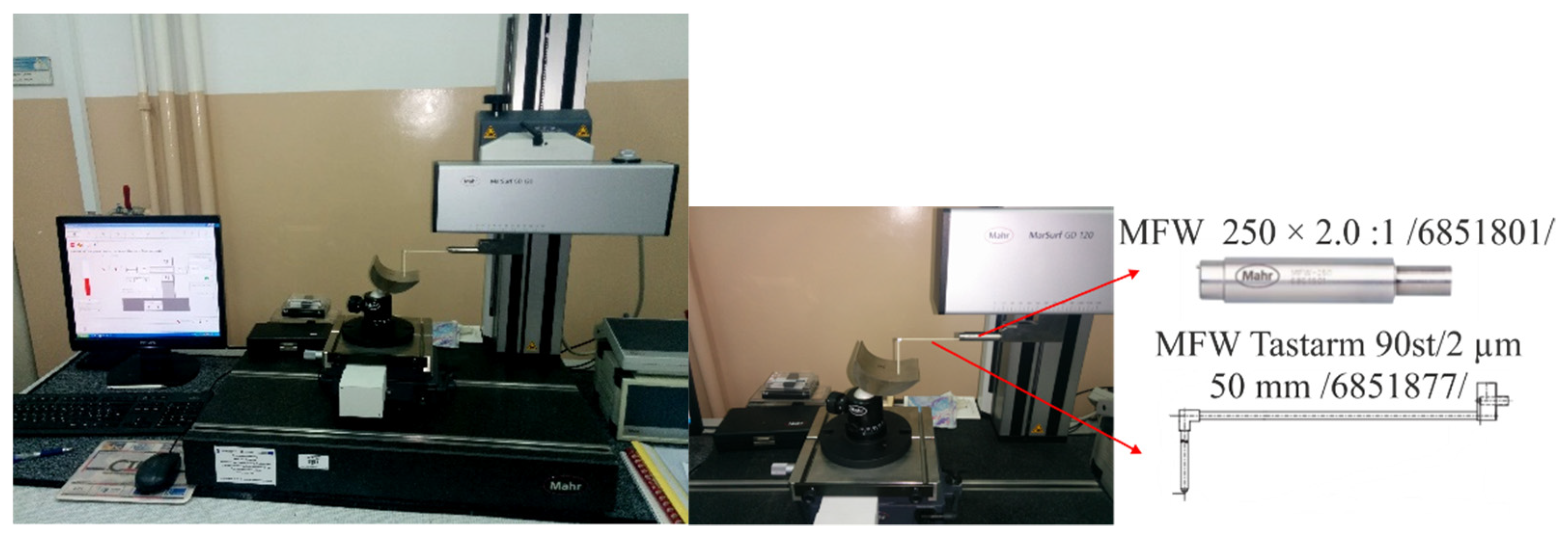
2.3. Experimental and Empirical Procedure and Research Technology

The purpose of the experiments was to study the effects of different axis orientations of the toroidal milling cutter and variability of the radius of curvature on surface roughness and topography. The two-factor test was used for the experiments, and the lead angle and the radii of curvature were changed to explore the effect of each on the surface roughness and topography. The tests were conducted based on the study object, which is presented in Figure 5.
The features of the research object are presented in Table 3.
The input variables of the test object (i.e., the angle α and the curvature radius ρ) as well as the limitations for carrying out experimental tests were selected after taking into account the conclusions of the simulation tests conducted by the author at work [2]. When the diameter D and the radius of the round cutting insert rp of the toroidal cutter are known as well as the radius of curvature ρ1 of the currently processed surface profile, it is possible to determine the value of the minimal lead angle αmin from relation (2), where the undercutting will not occur:
α m i n = arcsin ( D 2 r p ρ 1 r p )
The convex surface and concave surface were divided into test areas according to the variable values of the curvature radius ρ1 and the lead angle α, as shown in Figure 6.
Table 4 shows the machining parameters for the concave surface and convex surface of the turbine blade. For each of the processing steps, the fixed parameters were: axial infeed ap; radial infeed ae; feed per tooth fz; toroidal cutter diameter D = 16 mm; and the radius of the round cutting insert rp = 4 mm. In addition, in order to avoid undercutting of the concave surface, the limit value of the lead angle was calculated (αmin = 7°) for the radius ρ1 = 40 mm of this surface.
The test stand was built on the basis of the DMG DMU 100 MonoBlock 5-axis milling center, which is shown in Figure 7.
The machine was equipped with NC (Numerical Control) dividing heads and tools for roughing and finishing machining of the test object. The DMU 100 MonoBlock machine tool has a milling head with a built-in spindle with a maximum rotational speed of n = 24,000 1/min (axis B), enabling the setting of the tilt angle β. The head is equipped with the HSK-A63 chuck, intended for fixing the holder together with the toroidal cutter. In addition, equipping the machine tool with NC subdivision heads (dividing heads, axis A) enables the setting of the lead angle α. The SINUMERIK 840Di control system enables the realization of simultaneous 5-axis machining. The movement in the Z axis is carried out by the machine table, while the movement in the X and Y axes is carried out by the milling head.
To measure the 2D surface roughness and 3D topography parameters, a MAHR MarSurf GD 120 profilograph was used, which is shown in Figure 8. The measurement was done with the MFW 250 × 2.0:1 head with the measuring tip MFW Tastarm 90st/2µm_6851877, with the rounding radius of 2 µm.
The measurements were conducted by means of the contact method using MarWin software version 6268201 Mahr firm. This software allowed for the determination of the value of the selected 2D and 3D surface roughness parameters. The 2D roughness measurement was carried out in the feed direction of the toroidal milling cutter with the measurement being repeated three times, then the average values were calculated. The measurements were done along the measuring tracks, which were defined in the MarWin program as the upper profile line (red line), lower profile line (blue line), and middle profile line (green line). The measurement method is shown in Figure 9. Then, the 3D roughness parameters were measured. Therefore, the 2D roughness parameters in the perpendicular direction to the feed were not analyzed. The estimation of 3D topography parameters was made by scanning the area of the measured surface (the green surface area in Figure 9). The dimensions of the scanning surface area were 2.5 mm × 4 mm in the x and y axes, respectively. The measuring speed was 0.5 mm/s. The displacements during sampling were equal in the x direction: ∆x = 0.5 µm and in the y direction: ∆y = 19.4 µm.
Model studies were carried out using a three-level complete static plan PS/DK 3n, with the number of repetitions r = 3 and the assumed significance level τ = 0.05. The matrix of the study plan is shown in Table 5. This plan allows the empirical mathematical model of the investigated process to be obtained in the form of a polynomial function convenient for a mathematical analysis and model tests. In addition, this plan takes into account the interactions between the factors studied.
Table 6 shows the ranges of the analyzed values parameters of the lead angle α and the curvature radius ρ1 for individual test areas.

3. Results and Discussion

In industrial practice, in the field of mechanical engineering, mainly the parameters Ra, Rz, Sa, and Sz are used, which on their basis the surface roughness class is determined. Therefore, these parameters were analyzed in this study. In addition, these parameters are the easiest to adopt in a CAM system.

3.1. Surface Roughness

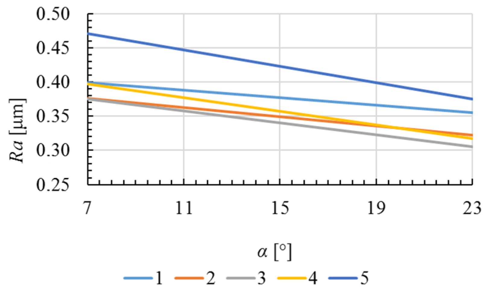
3.1.1. Ra Roughness Parameter

The relationship between surface roughness (Ra parameter, arithmetical mean height) and the lead angle and the curvature radius of the convex and concave surface are shown in Figure 10.
Based on the results of the studies, it was found that both in the machining of the convex and concave surface of the turbine blade, the maximum values of the Ra roughness parameter were obtained for the upper level (ρ1 = 400 mm and ρ1 = 120 mm, respectively) of the tested curvature radius. The lowest values of the Ra parameter were obtained for the middle level (ρ1 = 215 mm and ρ1 = 80 mm, respectively). It was noted that with an increase of the lead angle α, the Ra parameter decreased by about 20% for both the convex and concave surface. For the machining of the convex surface, the maximum value of 0.5 μm of the Ra parameter was noted in the first test area, while in the machining of the concave surface in III area, it reached a value of about 0.4 μm.
In the next step for the measured values of the Ra roughness parameter, the calculations were made according to the adopted test plan. As a result of the calculations, model functions of the test object were obtained, which showed the course of the Ra parameter in the machining of the convex (6) and the concave surface (6) of the turbine blade within the established range of the tested parameters ρ1 and α:
Ra = 0.556 – 0.0057α – 0.00085ρ1 + 0.0000023ρ12
Ra = 0.1986 + 0.0428α – 0.0008ρ1 – 0.00008α2 + 0.00001ρ12
The courses of the models’ dependences that describe changes of the Ra roughness parameter values in machining the convex and concave surface of turbine blade as a function of the radius of curvature ρ1 and the lead angle α are shown in Figure 11, Figure 12, Figure 13 and Figure 14, respectively.
As shown in the graphs, in the case of the convex surface within a scope of the radius of curvature ρ1 = 30 ÷ 175 mm, there was a slight decrease in the value of the Ra roughness parameter as the parameter ρ1 increased. Whereas, above the value of about 175 mm of radius ρ1, along with the increase of this parameter, the Ra parameter also increased. In the case of a concave surface, the value of the Ra parameter also slightly decreased with an increase in the radius of curvature ρ1 to about 80 mm. Above this value, the Ra roughness parameter increased, together with a growth of parameter ρ1. This is due to the change on the contact zone and the elongation of the toroidal cutter cutting edge contact line with the machined surface. The highest values of the Ra parameter were obtained in surface machining with a fixed angle α = 4°, and the lowest in machining with a fixed angle α = 18°. The highest values of the Ra parameter in the concave surface machining were obtained for the lead angle α = 7°, and the smallest for the angle α = 23°. The highest values of the Ra parameter in the concave surface machining were obtained for the lead angle α = 7°, while the smallest values were obtained for the angle α = 23°.

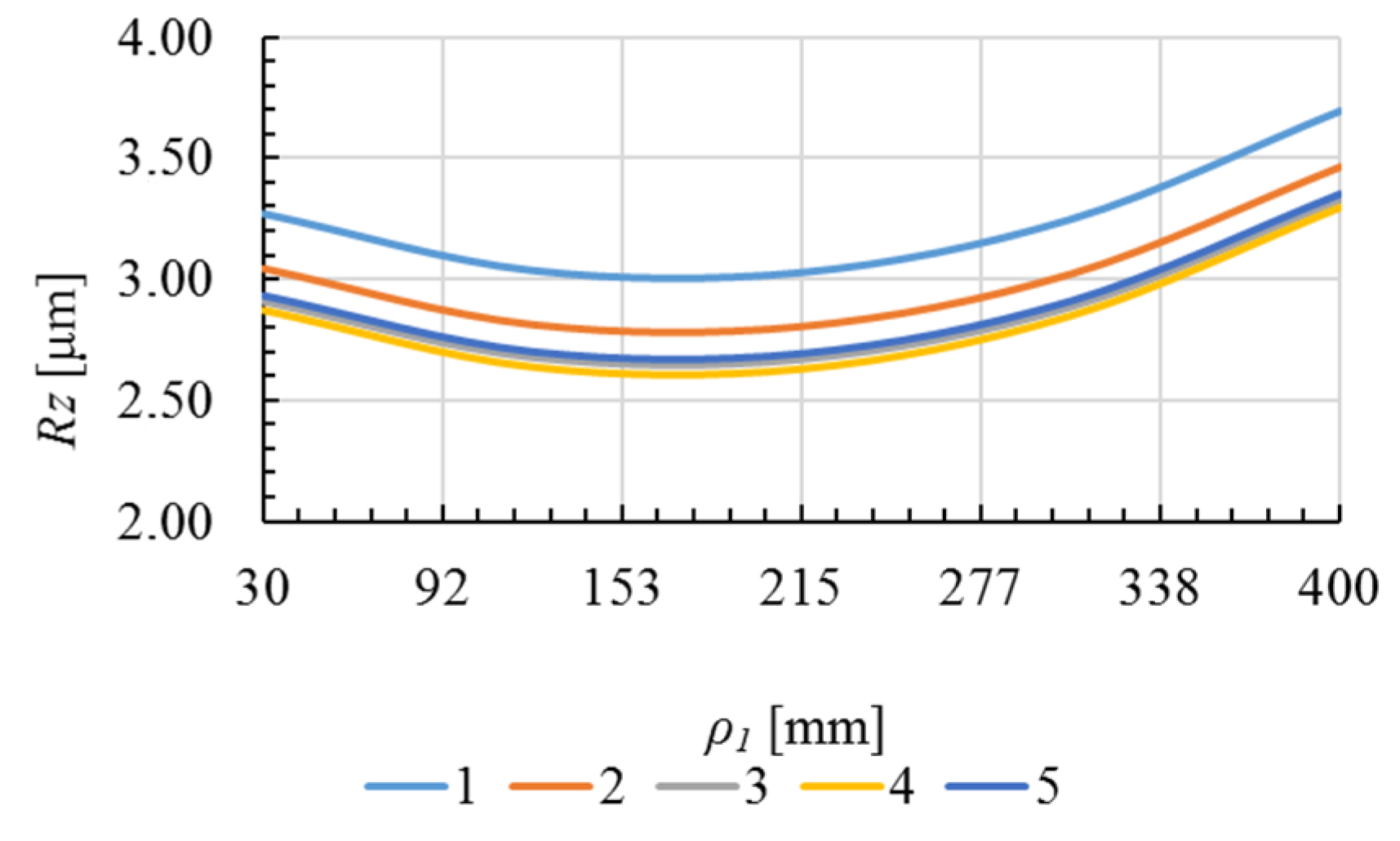
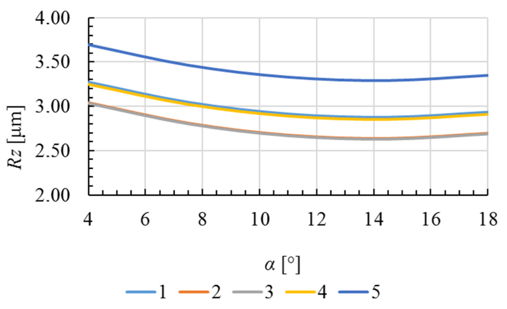
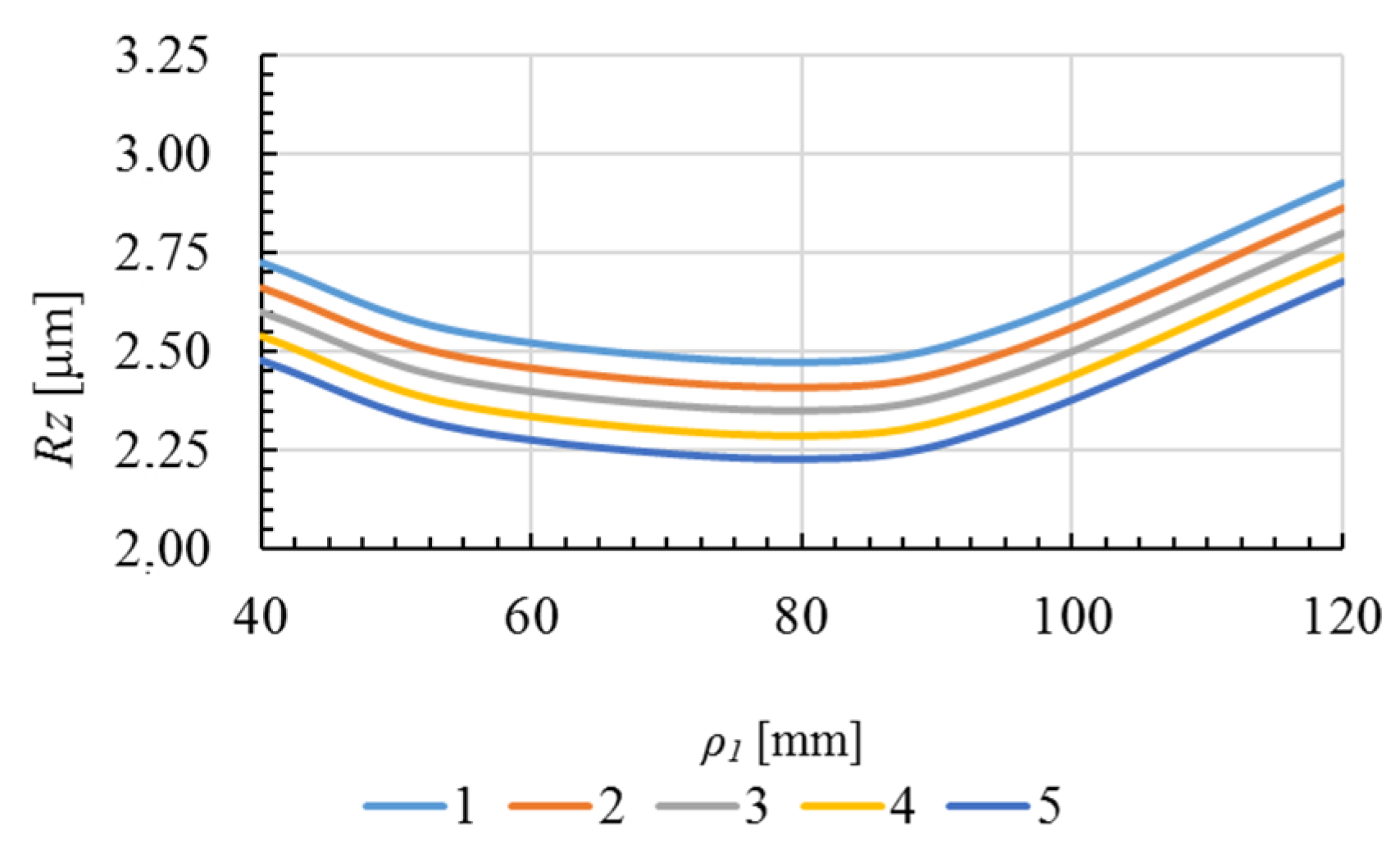
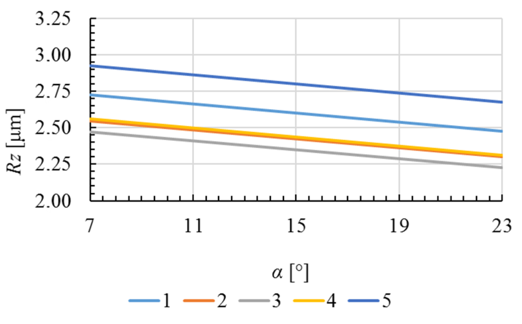
3.1.2. Rz Roughness Parameter

The relationship between surface roughness (Rz parameter–maximum height of profile) and the lead angle and the curvature radius of the convex and concave surface are shown in Figure 15.
Based on the results from the measurement of the Rz parameter values, it was found that the maximum values of this roughness parameter were obtained for the upper level (ρ1 = 400 mm and ρ1 = 120 mm, respectively) of the tested radius of curvature ρ1, while the lowest values of the Rz parameter were obtained for the middle level (ρ1 = 215 mm and ρ1 = 80 mm, respectively). This was observed in the entire investigated range of the radius of curvature ρ1 of the convex and concave surface subject of the research. An increase in the value of the lead angle α caused a decrease in the Rz parameter value of about 10%. The maximum value of Rz parameter of about 3.5 μm was measured in the first test area of the convex surface, and in the sixth area of the concave surface where Rz was about 2.5 μm.
Then, for the measured values of the Rz roughness parameter, some calculations were made according to the adopted test plan. As a result of the calculations, model functions of the test object were obtained that showed the course of the Rz parameter in the machining of the convex (8) and the concave surface (9) of the turbine blade within the established range of the tested parameters ρ1 and α:
Rz = 4.26 – 0.15α – 0.0068ρ1 + 0.0038α2 + 0.000013ρ12
Rz = 3.165 – 0.03α – 0.0385ρ1 + 0.000022ρ12
The courses of the models’ dependences that describe the changes of the Rz roughness parameter values in machining the convex and concave surface of the turbine blade as a function of the curvature radius ρ1 and the lead angle α are shown in Figure 16, Figure 17, Figure 18 and Figure 19, respectively.
As shown in the graphs, along with an increase in the curvature radius ρ1 to the value of about 215 mm for the convex surface, the value of the Rz parameter decreased. Above the value of ρ1 of approximately 215 mm, the Rz parameter increased again. However, in the whole tested range of the lead angle α, from the value of the parameter ρ1 = 40 mm to about ρ1 = 80 mm of the concave surface, the Rz roughness parameter decreased., whereas in the range of parameter ρ1 from about 80 mm to about 120 mm, the value of the Rz roughness parameter increased again. In this case, it may be due to the increase in the height of the tops and the depth of the roughness grooves. This was the result of the change in the contact zone and the elongation of the toroidal cutter’s cutting edge contact line with the machined surface. It was also found that as the value of the angle α increased, the value of the Rz parameter in machining the convex surface decreased. The exception was the radius of curvature ρ1 in the range of about 300÷400 mm, where the value of this parameter grew slightly. On the other hand, as the angle α increased, the Rz value of the concave surface roughness decreased over the entire range of the values for the curvature radius ρ1 tested.

3.2. Surface Topography

The next stage of the research was to carry out measurements of 3D surface geometry in selected places of the convex and concave surface of the turbine blade. Histograms of the values of the selected 3D parameters obtained from measurement in individual areas of the analyzed surfaces are shown in Figure 20, Figure 21, Figure 22 and Figure 23.
When analyzing the results of measuring parameters Sa (arithmetic deviation of the surface) and Sz (maximum height of the surface) of the convex surface, it was found that the values of these parameters went up with an increase in the curvature radius ρ1. However, in the case of the concave surface, it was observed that for the value of the angle α = 7°, along with the increase in the value of the radius ρ1, there was a slight increase in the values of parameters Sa and Sz. For the angle α = 15°, the smallest values of parameters Sa and Sz were obtained for the radius ρ1 = 80mm, while the largest was obtained for the radius ρ1 = 120 mm. For the angle α = 23°, a slight decrease in the value of the analyzed parameters along with an increase in parameter ρ1 was observed.
The topography images of the convex and concave surface of the turbine blade in individual test areas after machining are shown in Figure 24, Figure 25, Figure 26, Figure 27, Figure 28 and Figure 29.
When analyzing the presented images of the topography of the convex and concave surface, it was observed that in the structures of these surfaces, there was periodicity in the x-axis and y-axis direction. This was due to the machining marks created as a result of feed on the tooth of the toroidal cutter in a specific longitudinal direction (x-axis) and cross direction (y-axis). A mutual overlapping of traces (grooves) of adjacent transitions (rows) of the toroidal milling cutter was observed. It was also noted that along with the increase in value of the lead angle α, both in the machining of the convex and concave surface, extended grooves of the profile in the feed direction were obtained correspondingly. This indicates the extension of the active length of the cutting edge of the toroidal milling cutter. In addition, it was observed that as the value of this angle increased, higher profile tops were obtained correspondingly. This may indicate the residual material on the machined surface. These residues result from the reduced contact area between the tool and the machined surface due to the inclining of the mill axis in the feed direction. As a result of these residues, higher values of the parameter Sa of both analyzed surfaces were obtained after machining with larger settings of the lead angle α.
In addition, it was found that the resulting convex surfaces with a profile radius ρ1 = 30 mm and ρ1 = 215 mm after milling with a specified lead angle α = 4° and α = 11° had plateau-shaped tops. In other cases, the areas of the convex and concave surfaces had sharpened tops. Based on the analysis carried out, it was found that the surfaces obtained as a result of the machining were of an anisotropic mixed periodic nature.

4. Summary

This article focused on the 5-axis milling process of the sculptured surface of a turbine blade with a curved line contour and studied the influence of toroidal cutter axis orientation and curvature radius on surface roughness and topography for a curved surface. On this basis, the conclusion was applied to the turbine blade sculptured surface machining process, and the tool axis orientation and variable radius of curvature were studied simultaneously. The results can be summarized as follows:
1)
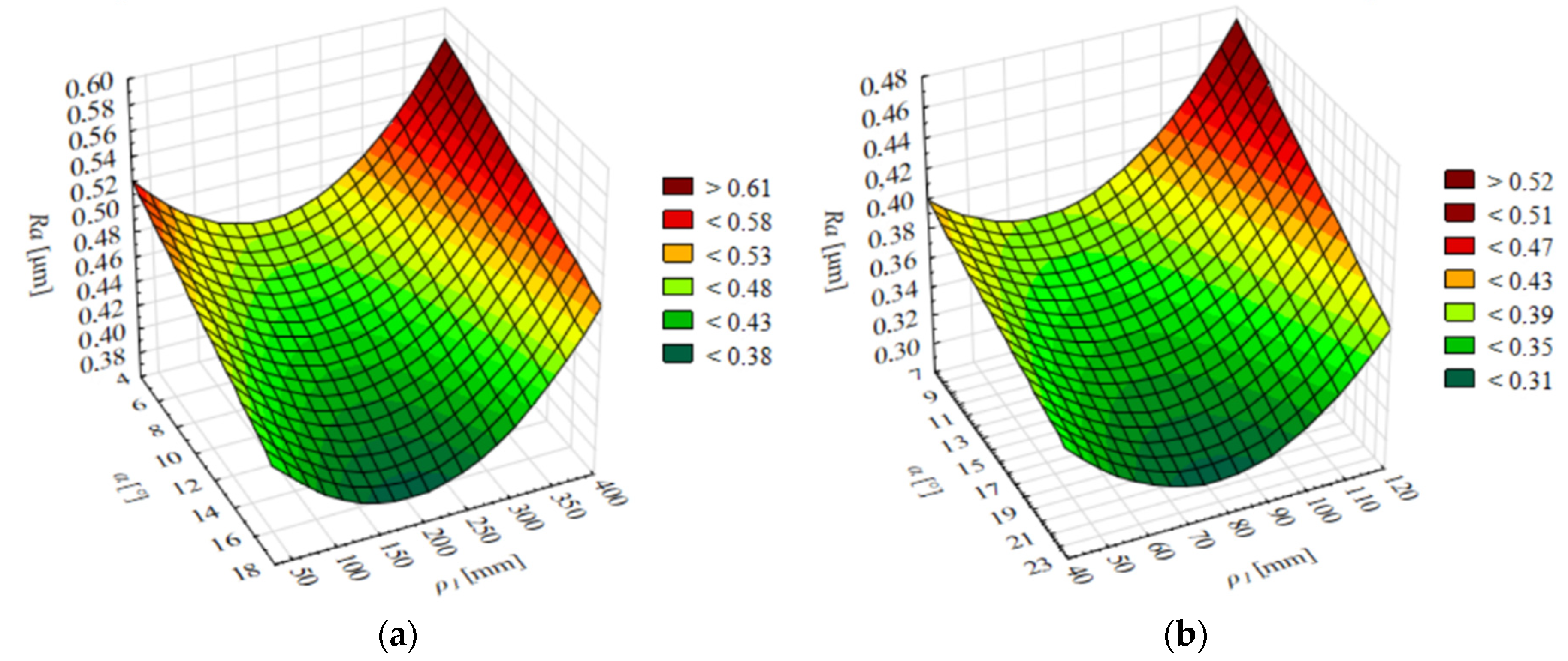
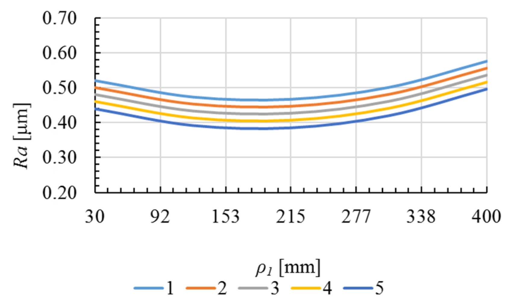
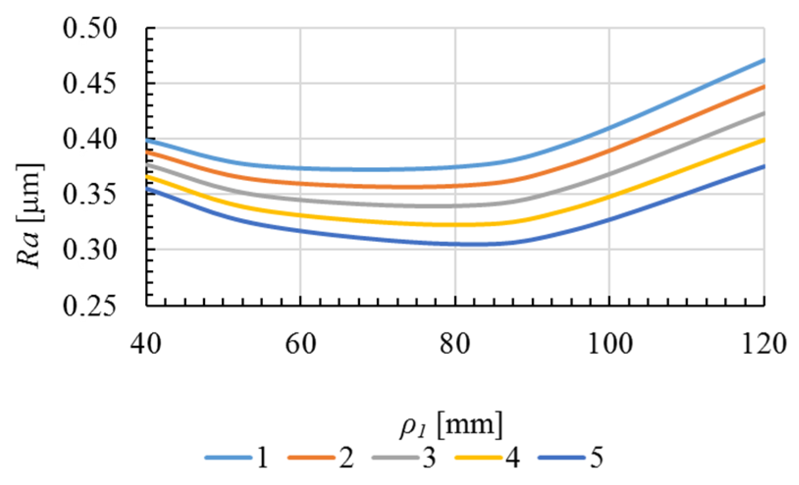
Both the curvature radius ρ1 and the lead angle α affected the surface roughness and topography of the convex and concave surface of the turbine blade. An increase in the value of the lead angle α across the entire established range caused the reduction in the roughness Ra and Rz parameters in both cases of the analyzed surfaces.
2)
It was shown that the nature of the changes in the Ra and Rz parameters of the convex and concave surface roughness was nonlinear with an upward trend with an increase in the radius of curvature ρ1. The largest growth in the value of these parameters occurred above the radius values ρ1 = 175 mm for a convex surface and ρ1 = 80 mm for a concave surface.
3)
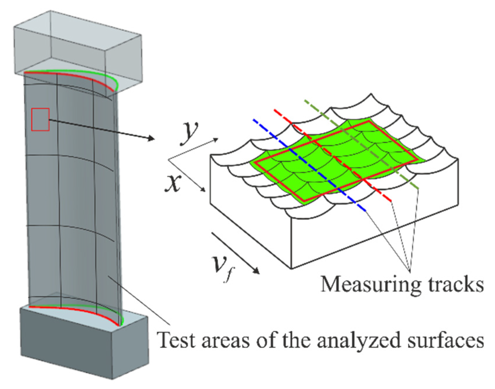
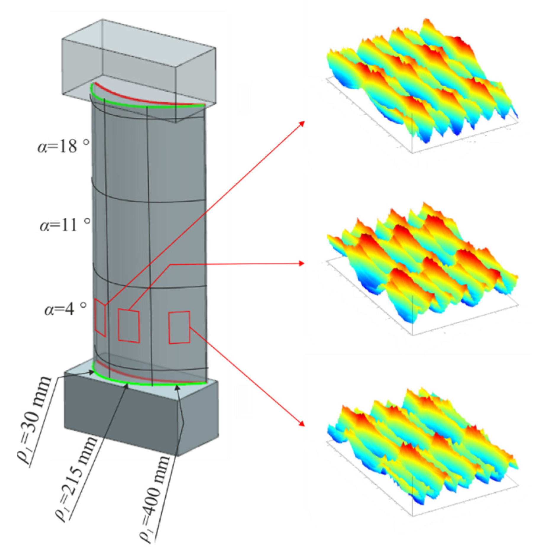
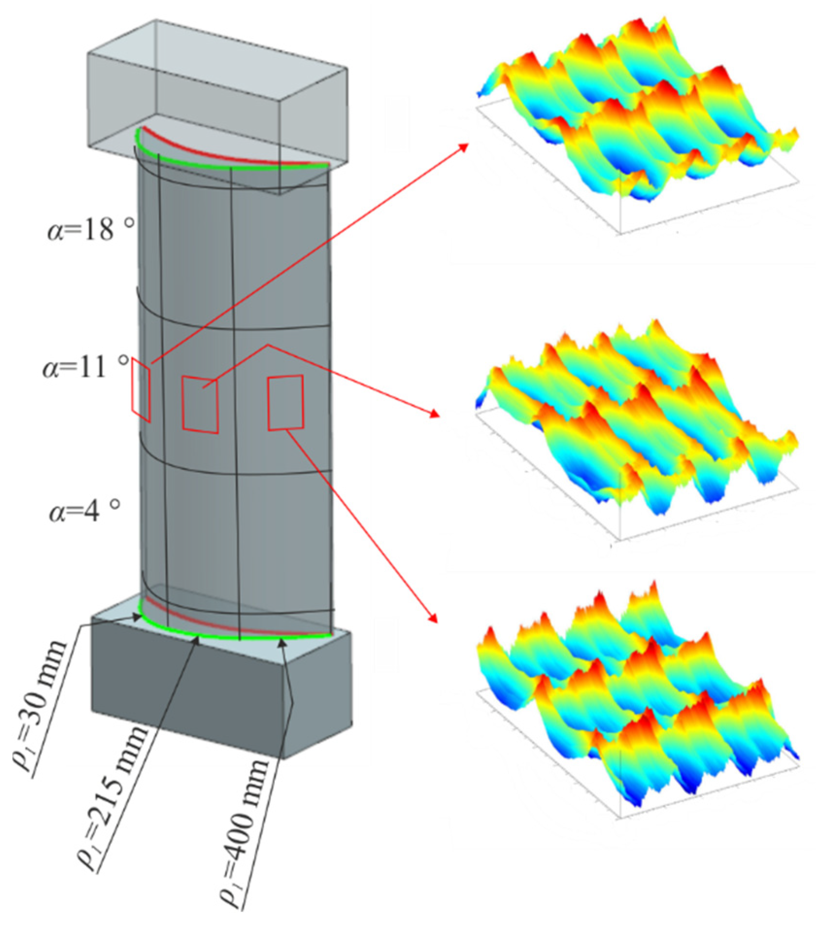
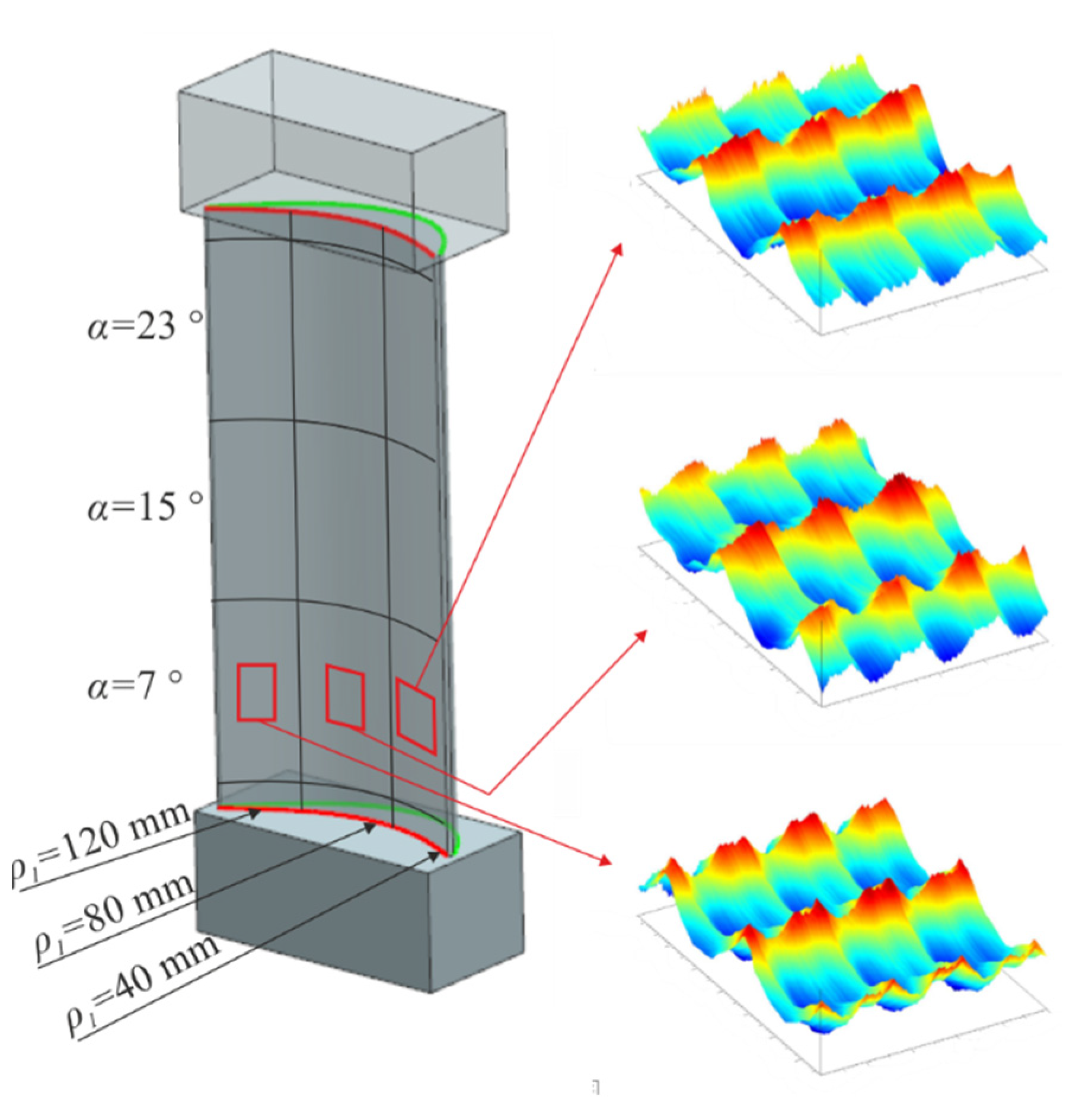
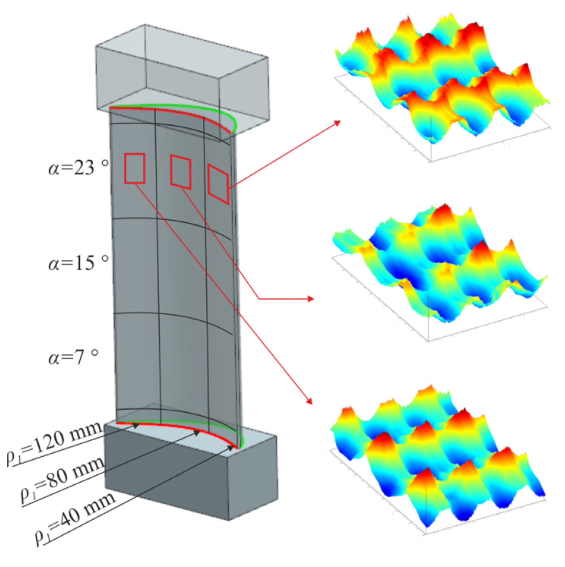
Within the range of the tested values of the angle α and the curvature radius ρ1, the geometrical structure (topography) of the convex and concave surface was characterized by periodicity in the feed direction of the tool, and in the transverse feed direction of the tool. It was found that the periodicity of these surfaces mainly depended on the kinematic and geometric mapping of the round cutting insert of the toroidal cutter on the machined surface.
4)
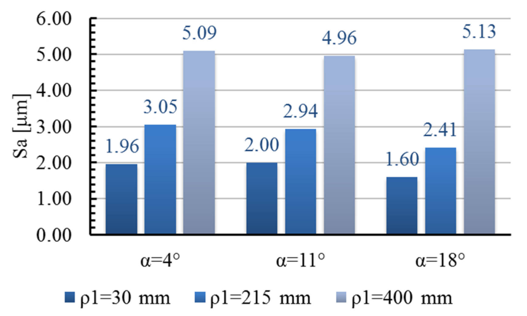
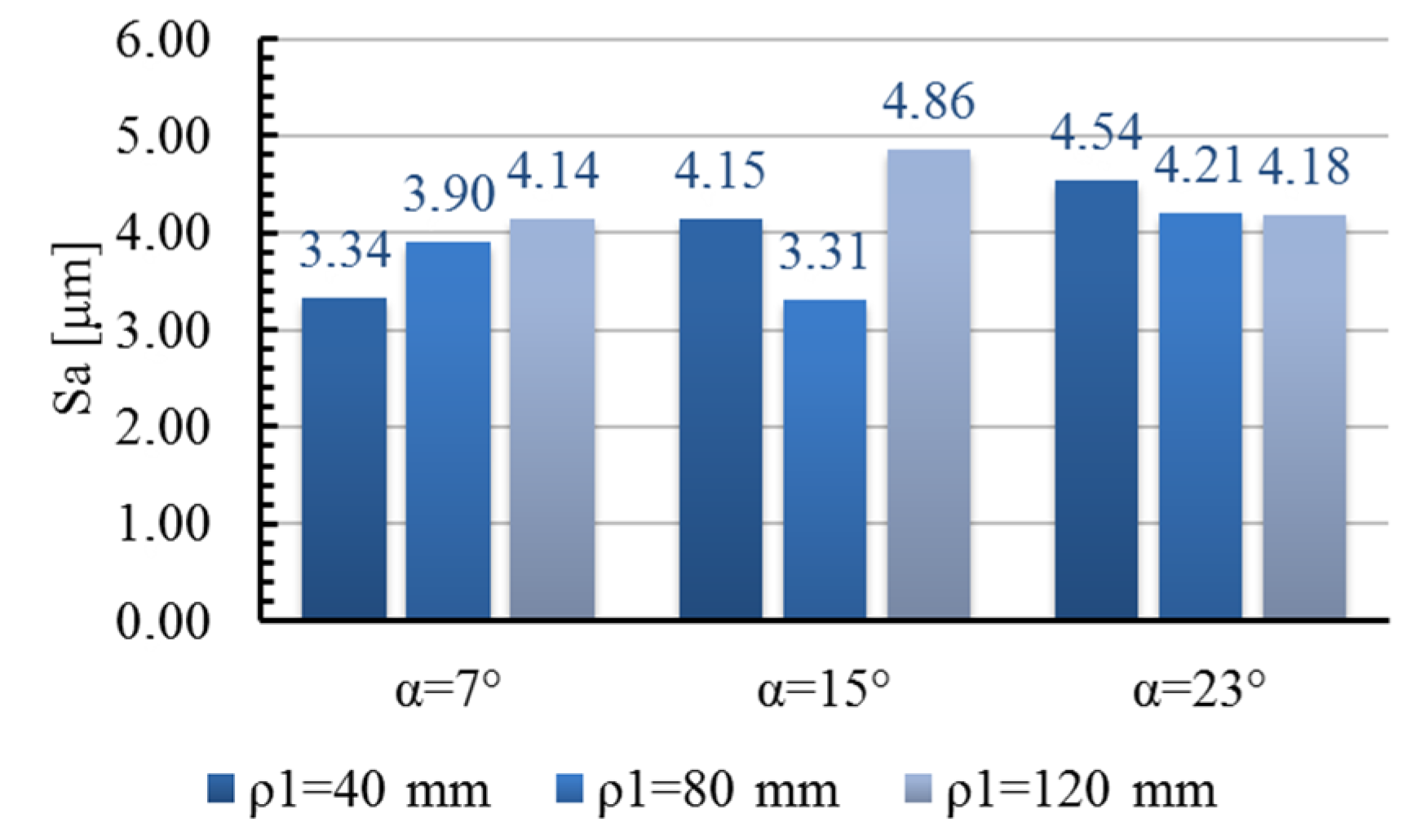
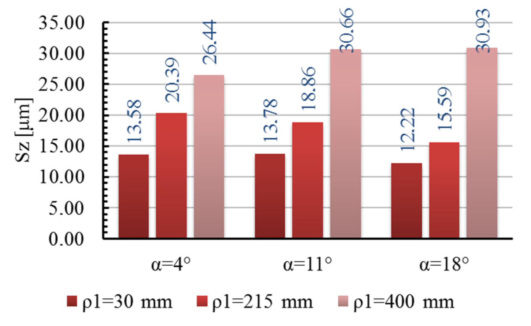
It was found that the values of the Sa and Sz parameters of both analyzed surfaces increased with a growth in the radius of curvature ρ1. In these cases, no significant influence of the α angle on the above parameters was found.
5)
It was also found that within the lower and middle level of the lead angle α values tested, the obtained surfaces had plate-shaped hills, while within the middle and upper level of the angle α parameter, these surfaces had sharpened hills.
6)
It was observed that as the value of the lead angle α increased, the active cutting edge length of the toroidal cutter was lengthened and the roughness profile grooves were lengthened in the direction of feed.
To sum up, it can be stated that the values of the lead angle α in the machining of the turbine blade surfaces with a variable profile curvature should be appropriately changed in a continuous way along with the change in the curvature radius ρ1 of a machined profile. A continuous change of the lead angle α can be carried out adaptively in CAM systems using the models developed in this paper, which is the subject of the author’s further research. The proposed adaptive method, after entering the criteria of the permissible parameter Ra and Rz of the surface roughness and Sa and Sz parameters of the topography, can allow for an adaption of the lead angle α of the toroidal cutter axis to the current value of the radius of curvature ρ1 of the sculptured surface during machining.

Author Contributions

Conceptualization, methodology, formal analysis, investigation, resources, data curation, writing—original draft preparation, writing—review and editing, visualization, M.G. All authors have read and agreed to the published version of the manuscript.

Funding

This research received no external funding.

Conflicts of Interest

The author declares no conflict of interest.

References

  1. Lavernhe, S.; Quinsat, Y.; Lartigue, C. Model for the prediction of 3D surface topography in 5-axis milling. Int J. Adv. Manuf. Technol. 2010, 51, 915–924. [Google Scholar] [CrossRef] [Green Version]
  2. Lim, T.-S.; Lee, C.-M.; Kim, S.-W.; Lee, D.-W. Evaluation of cutter orientations in 5-axis high speed milling of turbine blade. J. Mater. Process. Technol. 2002, 130–131, 401–406. [Google Scholar] [CrossRef]
  3. Wieczorek, B. Technologia Turbin Parowych, 1st ed.; Państwowe Wydawnictwa Techniczne: Warszawa, Rzeczpospolita Polska, 1961. [Google Scholar]
  4. Cao, Q.Y.; Zhao, J.; Zhu, L. The effect of curvature radius of sculptured surface on finish milling tool path selection. Int J. Adv. Manuf. Technol. 2017, 89, 3349–3357. [Google Scholar] [CrossRef]
  5. Yao, C.; Tan, L.; Yang, P.; Zhang, D. Effects of tool orientation and surface curvature on surface integrity in ball end milling of TC17. Int. J. Adv. Manuf. Technol. 2018, 94, 1699–1710. [Google Scholar] [CrossRef]
  6. Toh, C.K. Cutter path orientations when high-speed finish milling inclined hardened steel. Int J. Adv. Manuf. Technol. 2006, 27, 473–480. [Google Scholar] [CrossRef]
  7. Chen, X.; Zhao, J.; Dong, Y.; Han, S.; Li, A.; Wang, D. Effects of inclination angles on geometrical features of machined surface in five-axis milling. Int. J. Adv. Manuf. Technol. 2013, 65, 1721–1733. [Google Scholar] [CrossRef]
  8. Chen, X.; Zhao, J.; Dong, Y.; Li, A.; Wang, D. Research on the machined surface integrity under combination of various inclination angles in multi-axis ball end milling. Proc. Inst. Mech. Eng. Part. B J. Eng. Manuf. 2014, 228, 31–50. [Google Scholar] [CrossRef]
  9. Ko, T.J.; Kim, H.S.; Lee, S.S. Selection of the Machining Inclination Angle in High-Speed Ball End Milling. Int J. Adv. Manuf. Technol. 2001, 17, 163–170. [Google Scholar] [CrossRef]
  10. Kalvoda, T.; Hwang, Y.-R. Impact of various ball cutter tool positions on the surface integrity of low carbon steel. Mater. Des. 2009, 30, 3360–3366. [Google Scholar] [CrossRef]
  11. Hendriko, H. Mathematical Model for Calculating Scallop Height of Toroidal Cutter in Five-Axis Milling. J. Eng. Appl. Sci. 2017, 12, 5. [Google Scholar]
  12. Segonds, S.; Seitier, P.; Bordreuil, C.; Bugarin, F.; Rubio, W.; Redonnet, J.-M. An analytical model taking feed rate effect into consideration for scallop height calculation in milling with torus-end cutter. J. Intell. Manuf. 2019, 30, 1881–1893. [Google Scholar] [CrossRef]
  13. Erdim, H.; Lazoglu, I.; Ozturk, B. Feedrate scheduling strategies for free-form surfaces. Int. J. Mach. Tools Manuf. 2006, 46, 747–757. [Google Scholar] [CrossRef]
  14. Manav, C.; Bank, H.S.; Lazoglu, I. Intelligent toolpath selection via multi-criteria optimization in complex sculptured surface milling. J. Intell. Manuf. 2013, 24, 349–355. [Google Scholar] [CrossRef]
  15. Rao, A.; Sarma, R. On local gouging in five-axis sculptured surface machining using flat-end tools. Comput. Aided Des. 2000, 32, 409–420. [Google Scholar] [CrossRef]
  16. Chen, T.; Li, C.; Wang, H. Tool path generation for five-axis sculptured surface machining with a toroidal cutter. Int. J. Mach. Mach. Mater. 2010, 8, 372. [Google Scholar] [CrossRef]
  17. Xie, J.; Zou, M.; Cui, X. Effect of curvature distribution feature o complex freeform surface on cnc milling performance. J. Mech. Eng. 2009, 45, 158–162. [Google Scholar] [CrossRef] [PubMed]
  18. Duan, X.; Yu, S.; Peng, F.; Jiang, G. Study of the Effect of Tool Orientation on Surface Roughness in Five-Axis Milling of 300M Steel. IOP Conf. Ser. Mater. Sci. Eng. 2018, 382, 022087. [Google Scholar] [CrossRef]
  19. Yang, P.; Yao, C.; Xie, S.; Zhang, D.; Tang, D.X. Effect of Tool Orientation on Surface Integrity During Ball End Milling of Titanium Alloy TC17. Procedia CIRP 2016, 56, 143–148. [Google Scholar] [CrossRef] [Green Version]
Figure 1. Five-axis milling of sculptured surfaces elements with a curved line contour.
Metals 10 00932 g001
Figure 2. Effect of unevenly distributed roughness: (a) roughness builds up from the inlet side, (b) roughness builds up from the outlet side.
Metals 10 00932 g002
Figure 3. Analytical diagrams of tool orientation and tool contact position. (a) Tool orientation, (b) tool contact position.
Metals 10 00932 g003
Figure 4. Research 3D-CAD model of the turbine blade.
Metals 10 00932 g004
Figure 5. Structure of the research object.
Metals 10 00932 g005
Figure 6. Test areas depending on the curvature radius ρ1 and the lead angle α.
Metals 10 00932 g006
Figure 7. Test stand.
Metals 10 00932 g007
Figure 8. 3D profilograph MarSurf GD 120.
Metals 10 00932 g008
Figure 9. Methodology for measuring surface roughness and topography.
Metals 10 00932 g009
Figure 10. Influence of the lead angle α and radius of curvature ρ1 on the Ra roughness parameter of the convex (a) and concave (b) surface.
Metals 10 00932 g010
Figure 11. Effect of the curvature radius ρ1 on the Ra roughness parameter in the machining of the convex surface: (1) α = 4°, (2) α = 7.5°, (3) α = 11°, (4) α = 14.5°, (5) α = 18°.
Metals 10 00932 g011
Figure 12. Effect of the lead angle α on the Ra roughness parameter in the machining of the convex surface: (1) ρ1 = 30 mm, (2) ρ1 = 122.5 mm, (3) ρ1 = 215 mm, (4) ρ1 = 307.5 mm, (5) ρ1 = 400 mm.
Metals 10 00932 g012
Figure 13. Effect of the curvature radius ρ1 on the Ra roughness parameter in the machining of the concave surface: (1) α = 7°, (2) α = 11°, (3) α = 15°, (4) α = 19°, (5) α = 23°.
Metals 10 00932 g013
Figure 14. Effect of the lead angle α on the Ra roughness parameter in the machining of the concave surface: (1) ρ1 = 40 mm, (2) ρ1 = 55 mm, (3) ρ1 = 80 mm, (4) ρ1 = 95 mm, (5) ρ1 = 120 mm.
Metals 10 00932 g014
Figure 15. Influence of the lead angle α and radius of curvature ρ1 on the Rz roughness parameter of the convex (a) and concave (b) surface.
Metals 10 00932 g015
Figure 16. Effect of the curvature radius ρ1 on the Rz roughness parameter in the machining of the convex surface: (1) α = 4°, (2) α = 7,5°, (3) α = 11°, (4) α = 14,5°, (5) α = 18°.
Metals 10 00932 g016
Figure 17. Effect of the lead angle α on the Rz roughness parameter in the machining of the convex surface: (1) ρ1 = 30 mm, (2) ρ1 = 122.5 mm, (3) ρ1 = 215 mm, (4) ρ1 = 307.5 mm, (5) ρ1 = 400 mm.
Metals 10 00932 g017
Figure 18. Effect of the curvature radius ρ1 on the Rz roughness parameter in the machining of the concave surface: (1) α = 7°, (2) α = 11°, (3) α = 15°, (4) α = 19°, (5) α = 23°.
Metals 10 00932 g018
Figure 19. Effect of the lead angle α on the Rz roughness parameter in the machining of the concave surface: (1) ρ1 = 40 mm, (2) ρ1 = 55 mm, (3) ρ1 = 80 mm, (4) ρ1 = 95 mm, (5) ρ1 = 120 mm.
Metals 10 00932 g019
Figure 20. Statement of the measurement results of the parameter Sa of the convex surface of the turbine blade.
Metals 10 00932 g020
Figure 21. Statement of the measurement results of the parameter Sa of the concave surface of the turbine blade.
Metals 10 00932 g021
Figure 22. Statement of the measurement results of the parameter Sz of the convex surface of the turbine blade.
Metals 10 00932 g022
Figure 23. Statement of the measurement results of the parameter Sz of the concave surface of the turbine blade.
Metals 10 00932 g023
Figure 24. Topography of the convex surface when changing the curvature radius for the lead angle α = 4°.
Metals 10 00932 g024
Figure 25. Topography of the convex surface when changing the curvature radius for the lead angle α = 11°.
Metals 10 00932 g025
Figure 26. Topography of the convex surface when changing the curvature radius for the lead angle α = 18°.
Metals 10 00932 g026
Figure 27. Topography of the concave surface when changing the curvature radius for the lead angle α = 7°.
Metals 10 00932 g027
Figure 28. Topography of the concave surface when changing the curvature radius for the lead angle α = 15°.
Metals 10 00932 g028
Figure 29. Topography of the concave surface when changing the curvature radius for the lead angle α = 23°.
Metals 10 00932 g029
Table 1. Chemical composition of the Inconel 718 alloy in% of elements.
FeCrCoMoWNbAlTiCBZrNi
IN71818.19-3-5.10.50.950.050.04-525
Table 2. Main mechanical and physical properties of Inconel 718 nickel alloy.
Tensile Strength (MPa)Yield Strength (MPa)Elastic Modulus (GPa)Elongation (%)Density (g/cm3)
1330112022023%8.2
Table 3. Dimensions characteristic for the test object.
Description
Input variablesX1Lead angle α
X2Curvature radius ρ1
Output variablesY12D and 3D surface roughness parameters
Constant factorsC1Machine tool
C2Material
C3Toroidal cutter
LimitationO1Minimum lead angle αmin
Table 4. Machining conditions.
No.ParametersConvex Surface MachiningConcave Surface Machining
1.ap [mm]0.250.25
2.ae [mm]1.51.5
3.fz [mm/tooth]0.260.26
4.vc [m/min]4040
5.ρ1 [mm]ρ1 ∈ <30 ÷ 400>ρ1 ∈ <40 ÷ 120>
6.α [°]α ∈ <4 ÷ 18>α ∈ <7 ÷ 23>
Table 5. Studies’ plan matrix PS/DK 32.
Test NumberStandardized VariablesSquaresInteractions
x0x1x2x12x22x1 × 2
1++++++
2++0+00
3++-++-
4+0+0+0
5+00000
6+0-0+0
7+-+++-
8+-0+00
9+--+++
Table 6. Studies’ plan for the convex and concave surface of the turbine blade.
Test NumberConvex SurfaceConcave Surface
x1(α)x21)x1(α)x21)
11840023120
2182152380
318302340
41140015120
5112151580
611301540
744007120
84215780
9430740

