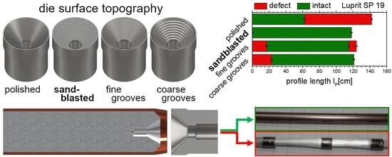
Indirect extrusion experiments with four different surface topographies on the die cone and two different lubrication conditions were carried out. When defining the billet geometry, two factors must be taken into account—material flow and preparation effort. For small flanging angles such as the applied 9°, only a small cross section of the copper is in contact with the die at the beginning of the process. Considering the low contact area, a high contact pressure and, consequently, intense interlocking of the copper and die cone surface is to be expected. Hence, this is disadvantageous for the material flow and, therefore, the flanging angle of 9° is classified unsuitable. Instead an angle identical to the semi die angle α is recommended. However, the disadvantage of large flanging angles, i.e., even more complex billet preparation and scrap production by machining, have to be considered when defining the billet geometry.
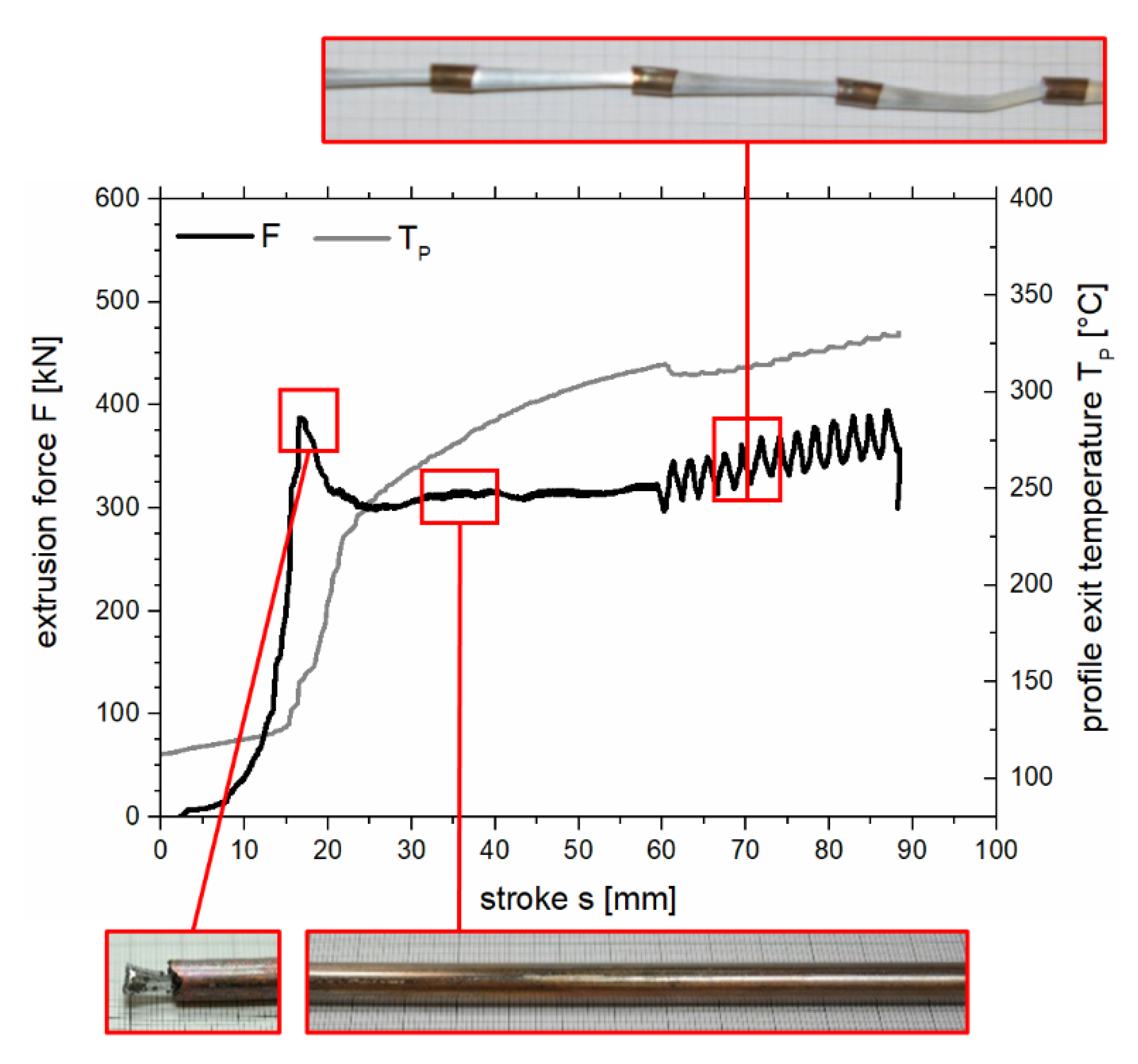
The investigation of the extrusion diagrams in
Figure 3,
Figure 4, and
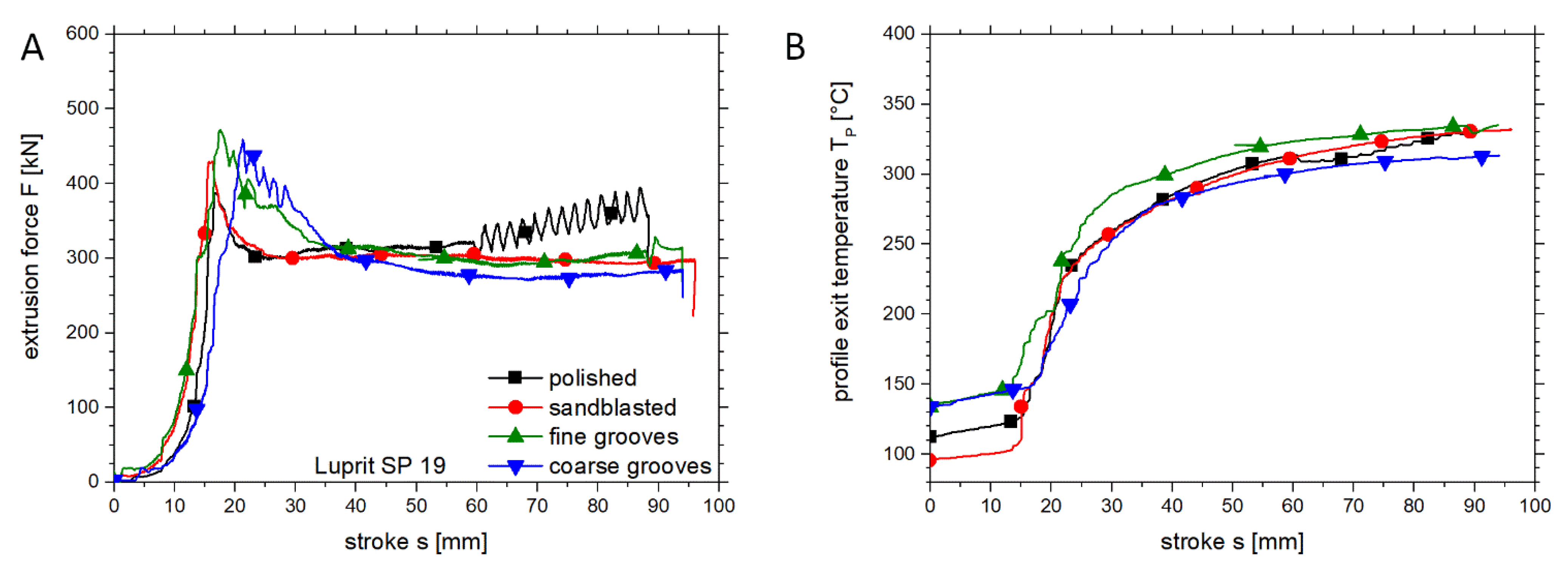
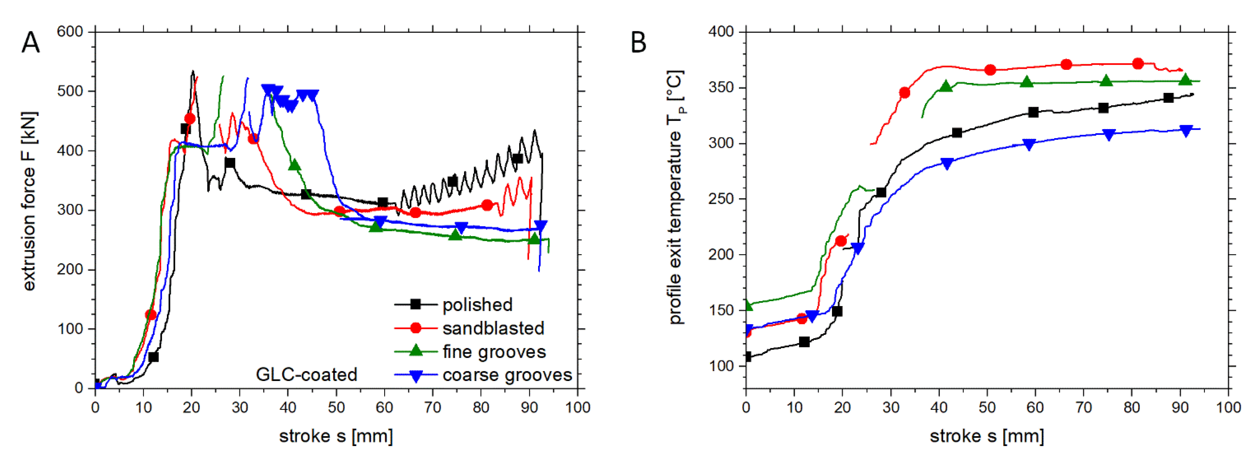
Figure 6 revealed oscillations and drops of the extrusion force as well as a stepwise increase of the profile exit temperature. The oscillations in the extrusion force can be explained by the recurring fracture of the copper sleeve since the number of oscillations observed in each extrusion diagram is equal to the number of sleeve fractures on the corresponding profile. Furthermore, the sleeve fractures are the cause for the stepwise increase of the temperature. Due to lacking contact between thermocouple and extruded copper during a sleeve fracture, the ambient temperature of the die is measured. Therefore, the curve stagnates until the thermocouple regains contact with the copper. In addition, the greatly slowed deformation of copper during the sleeve fracture causes significantly less heat generation. On the one hand, the deviation of the initial temperatures is caused by different residence times of the dies in the container during the loading process. On the other hand, the contact conditions between die and container vary due to wear of the container bore and, therefore, cause varying degrees of heat transfer.
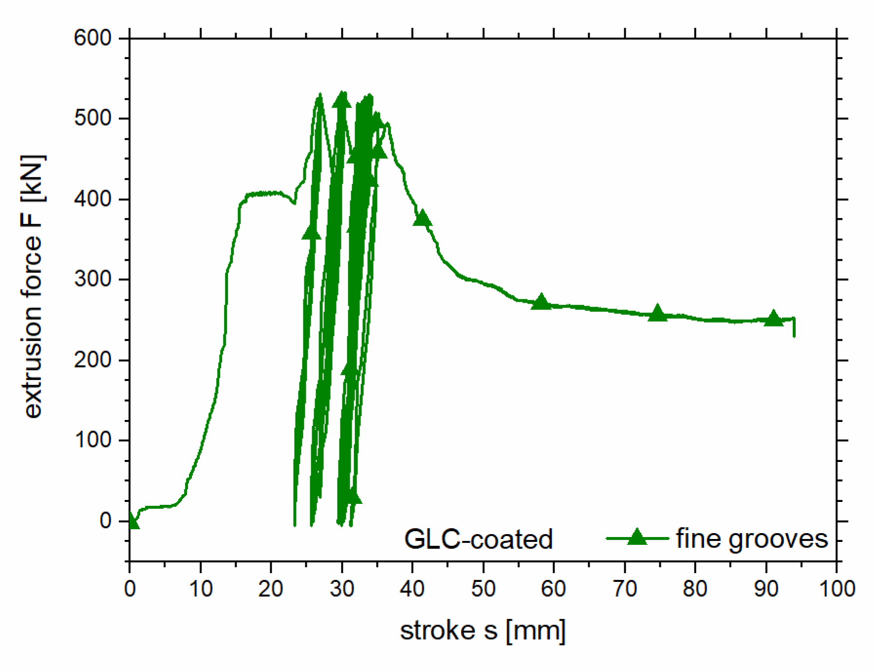
Another phenomenon, only observed in the extrusion diagrams of trials No. 6–8 with the GLC-coated dies (
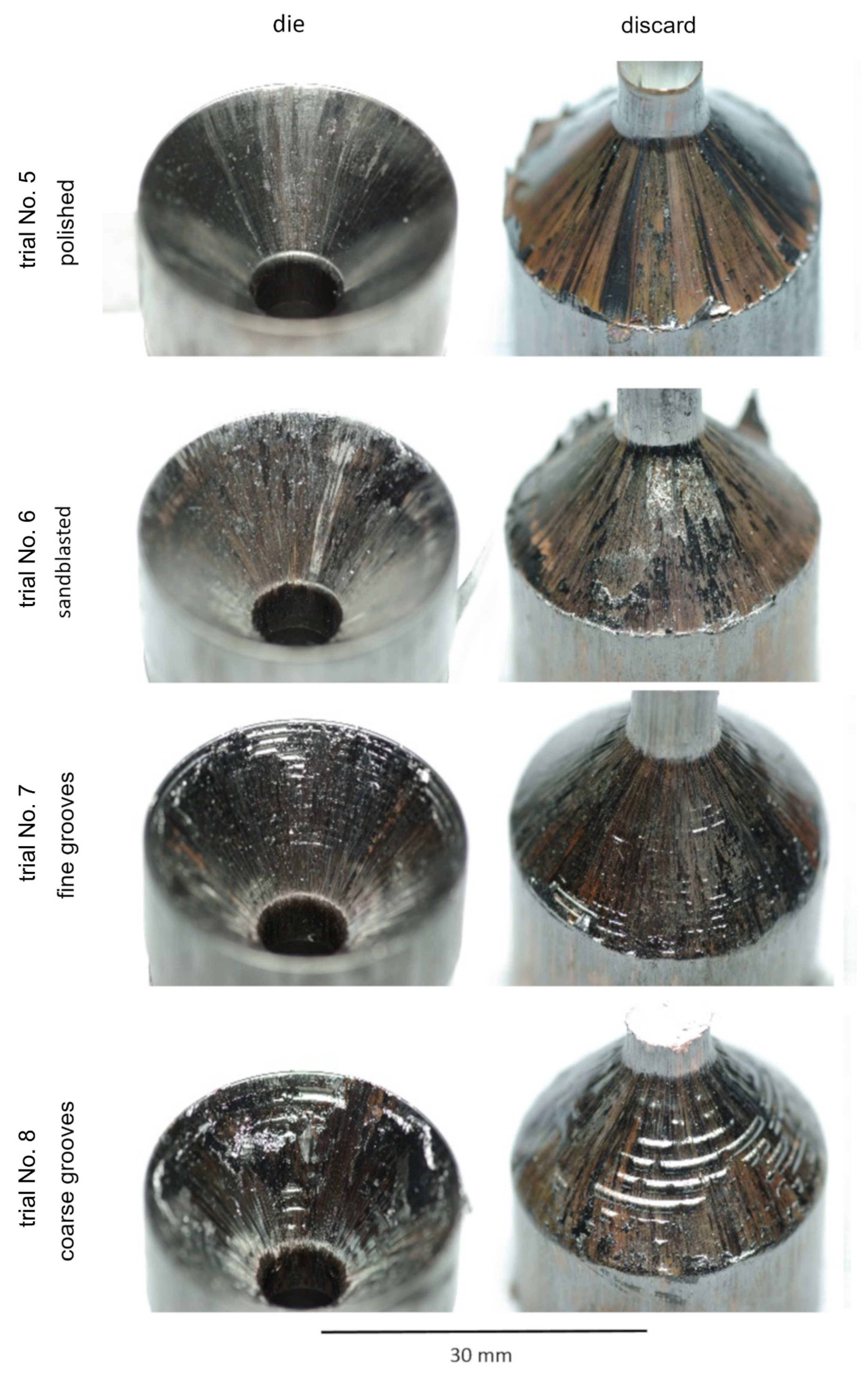
Figure 6A), is a more or less distinctive plateau at an extrusion force of approximately 410 kN. Since the coating is very thin and does not level the topography as the Luprit SP 19 does in trials No. 2–4, the copper is pushed into the depressions of the topography and clogs them. Therefore, the copper cannot slip on the lubricant, but is sheared off. This causes higher friction and, thus, retention of the copper. As a consequence, the extrusion of a distinct full aluminum head results, as shown in
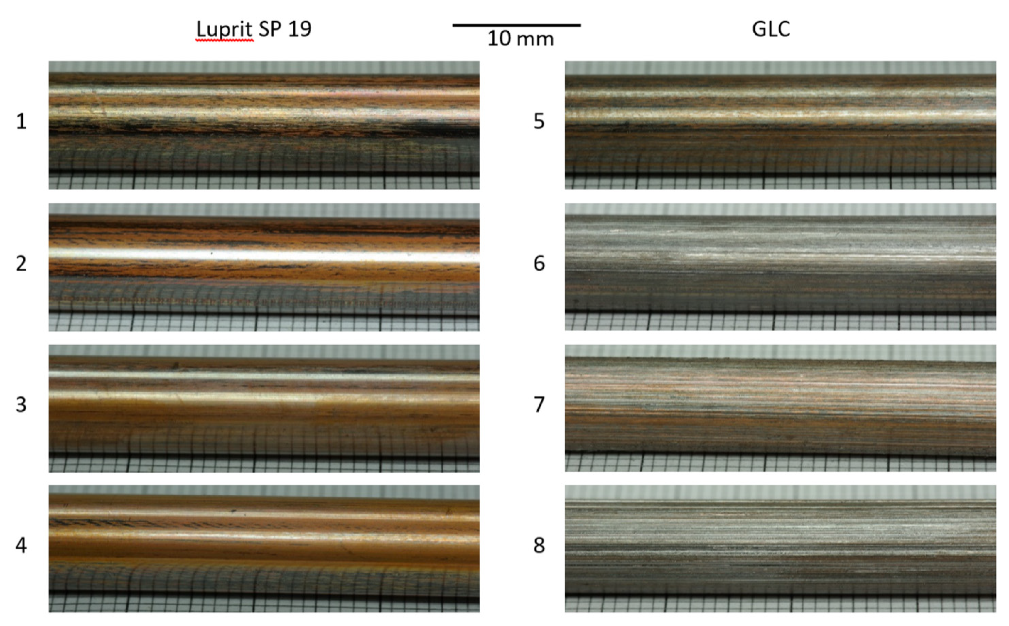
Figure 14, which depicts the tips of the front-sections from trials No. 5–8 with full aluminum heads of different lengths (23–280 mm). The length of the full aluminum head correlates with the width of the observed plateaus in the extrusion force shown in
Figure 6A. Thus, these plateaus are caused by solely extrusion of aluminum. Due to the smoothness of the polished die cone in trial No. 5, the GLC-coating produces reasonably good lubrication conditions and only a short full aluminum head is extruded.
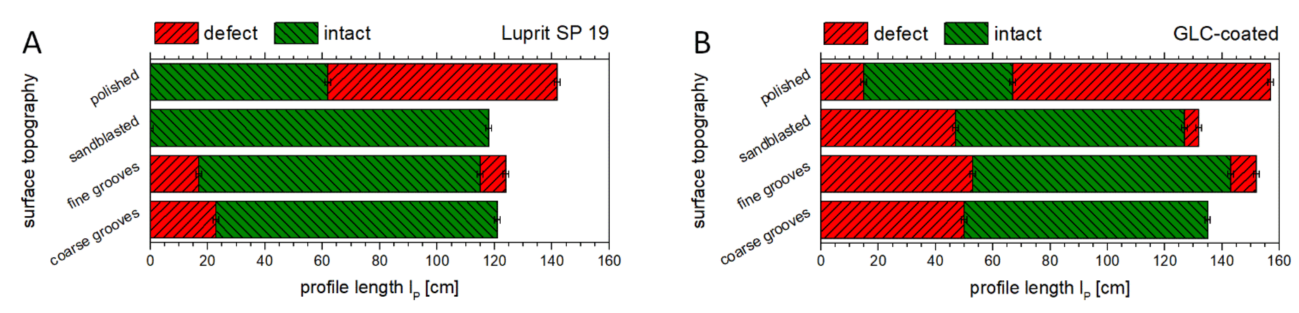
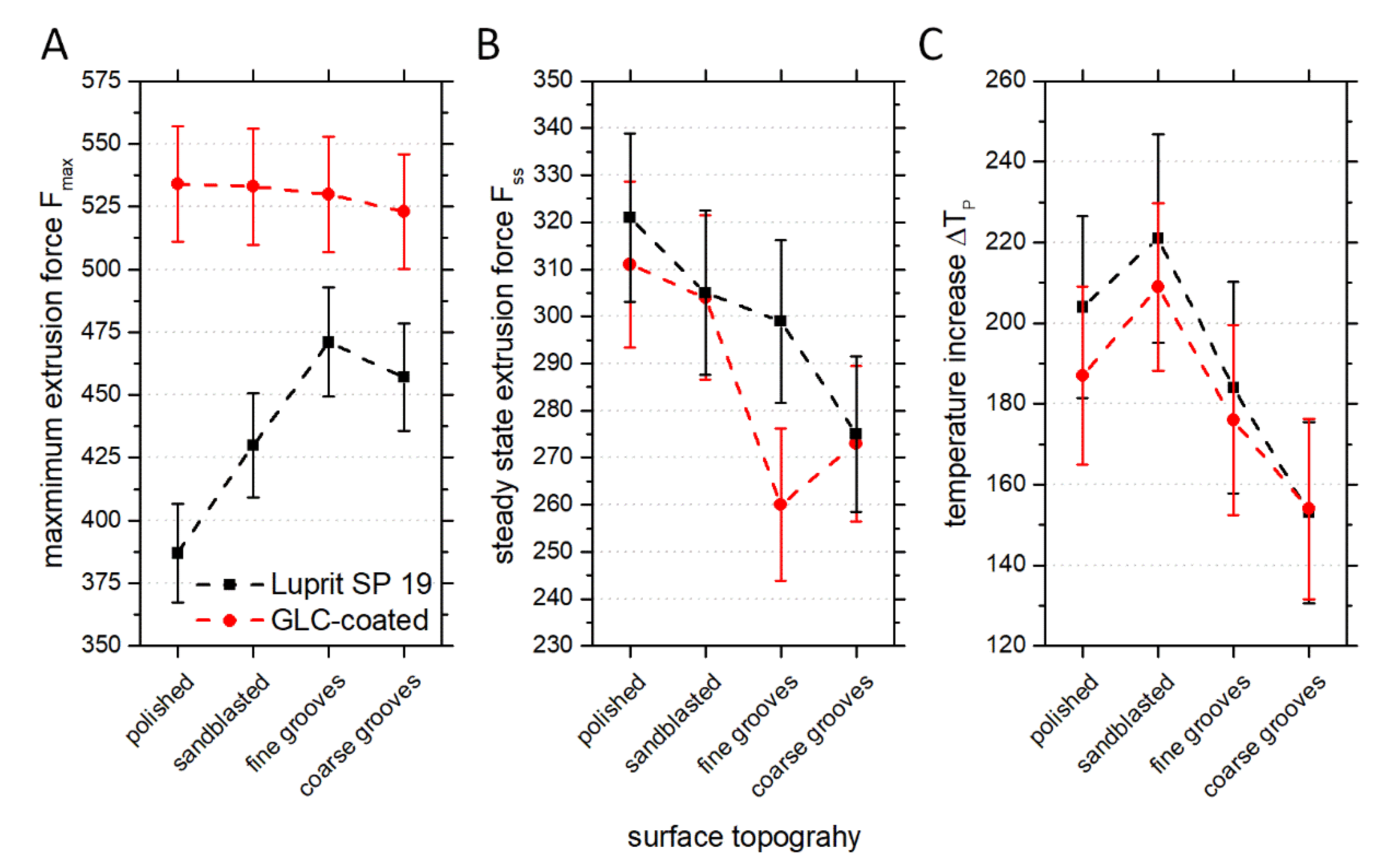
For the maximum extrusion force, an increase with reduced smoothness of topography for the tools lubricated with Luprit SP 19 can be seen in
Figure 7A. An explanation for this is likely the amount of macroscopic interlocking between copper and die surface during the unsteady beginning of the extrusion process. The low roughness of the polished surface causes mainly microscopic interlocking and the material flow is unaffected, apart from the friction. Due to the asperities of the sandblasted surface, macroscopic interlocking intensifies and the material flow is slightly impaired, which causes an increase of the maximum extrusion force. The applied grooves both cause severe macroscopic interlocking and, therefore, impair the material flow even more. Consequently, the maximum extrusion force is higher. Due to the similar geometry of fine and coarse grooves, there is only a little difference in the maximum extrusion force. It is supposed that the lower number of coarse grooves causes less negative affection of the material flow and, thus, a lower maximum extrusion force. This influence of the topography on the maximum extrusion force cannot be noticed for the tools with GLC-coating since the maximum load of the extrusion machine was reached in all four trials. These significantly higher maximum extrusion forces, 110–138% compared to the use of Luprit SP 19 and depending on the surface topography, illustrate the significance of the lubrication conditions. The GLC-coating seems to be unable to generate adequate lubrication conditions for good material flow and, therefore, the interlocking of copper and die surface is even more intense during the unsteady processes at the beginning of the extrusion. However, Luprit SP 19 clearly reduces the necessary forces and, thus, counteracts the interlocking to a certain extent. Another indication for less suitable lubrication conditions with lower smoothness of topography are both delayed transition to the quasi-steady state (
Figure 4A and
Figure 6A) and accumulated the occurrence of the initial sleeve fractures (
Figure 8). This was especially observed for the tools with fine and coarse grooves at both lubrication conditions (trials No. 3, 4, 7, and 8) as well as for the tool with sandblasted surface and GLC-coating (trial No. 6).
By comparing the quasi-steady state extrusion force in dependence on the die cone topography (
Figure 7B), a decrease of the extrusion force with decreasing smoothness of topography was observed. Since the extrusion forces in the quasi-steady state are partly very similar, although the lubrication conditions are very different, other factors, such as equivalent copper cross section and temperature development, also have to be considered. The combination of surface topography and lubrication condition defines the contact conditions between copper and die surface. For the use of Luprit SP 19, the contact area of both surfaces lowers with decreasing smoothness of the topography. In trial No. 1 with the polished die cone, the contact area is the largest and, thus, the friction is the highest. In trial No. 2, the depressions of the sandblasted topography are leveled by Luprit SP 19 and, thus, the contact is limited to the asperities of the topography and the friction is reduced. The tools with grooves (trial No. 3 and 4) have an even lower contact area with copper because the grooves are also leveled with Luprit SP 19. As a consequence, the contact is limited to the plateaus between the grooves. In all cases, Luprit SP 19 also acts as a lubricant on the contact surface of copper and die and a good product surface is generated (
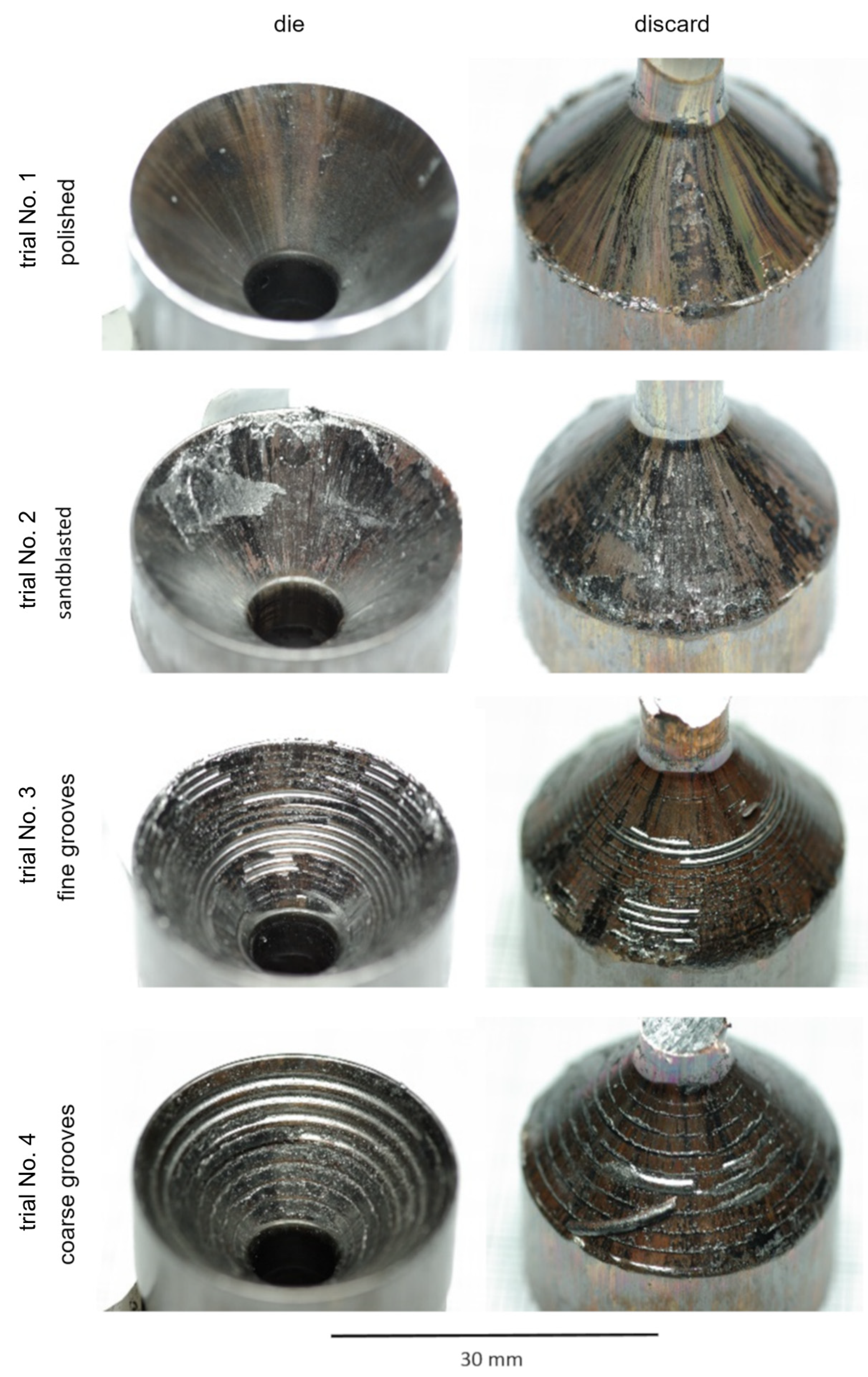
Figure 9). The deposited graphite on the product surfaces implies a steady conveyance of lubricant away from the lubricated contact surface. This lost lubricant is replaced by the Luprit SP 19 entrained by the billets’ surface from the container. In this way, a steady supply with lubricant is facilitated. For the tools coated with GLC, the contact conditions are very different. Although the layer also acts as a lubricant, it cannot level the depressions of the topography since it was applied uniformly on the whole surface. Hence, copper is pushed into the depressions, sheared off from the flowing material, and remains in the depressions (
Figure 13). High friction is caused by the interaction of sheared and flowing copper. Only by entrainment of Luprit SP 19 from the surface of the billet, the friction between sheared and flowing copper is reduced enough to accomplish a sound extrusion. The acceptable product surface quality of trial No. 5 shows the principle capability of GLC to facilitate good lubrication conditions on smooth die surfaces. However, the sandblasted surface is already too rough and an unsatisfactory product surface quality is fabricated. As mentioned before, the equivalent copper cross section and profile exit temperature or, in this case, the temperature increase must be considered as well when interpreting the quasi-steady state extrusion force. The former has a direct impact on the extrusion force due to the increase of the composite billets’ total flow stress with an increasing equivalent copper cross section. For the temperature increase, a considerable dependence on the die cone topography is noticeable and it is affected by several factors, i.e., friction, contact area of copper and die surface, initial temperature, heat introduced by the container, and heat generated by deformation. For both lubricants, the temperature increase is lower with decreasing smoothness of topography with exception of the polished surface. This effect is supposed to be caused by the lower heat generation by friction due to the decreasing contact surface of copper and die with decreasing smoothness of topography. The lower temperature increase in the case of the polished die may be caused by a different balance of heat generated by friction and dissipated into the tool. On the one hand, the large contact surface causes high friction and, thus, high heat generation. On the other hand, this heat can be dissipated very well into the tool because of the large contact surface. The effect of initial temperature on the temperature increase is a result of the non-isothermal process conditions and the temperature dependence of the heat transfer. At first, the billet is heated very quickly by the hot container as a consequence of the high initial temperature difference of approximately 300 °C. With equalization of the temperatures, the heat transfer is reduced and the temperature increase is slowed down. This is also expected to be the cause of the observed asymptotic approach to a maximum temperature. In addition, with increasing temperature, the heat generated by deformation is lowered due to lower flow stresses. Due to this and the long residence time of the billet in the container during the safety shutdowns, the curves of trial No. 6 and 7 reach a constant temperature level. The last point to be considered is the influence of sleeve fractures. As discussed before, the deformation of copper is slowed during the occurrence of sleeve fractures and less deformation heat is generated. Since this effect is cumulative, the more sleeve fractures are observed, the less temperature increase is expected. This is in accordance with the lower temperature increase (
Figure 7C) and the accumulated occurrence of sleeve fractures for the trials with GLC-coated dies (
Figure 8B). All these mentioned factors and their interactions influence the quasi-steady state extrusion force. Therefore, a clear identification of the main influences is not possible.


