Abstract
Fatigue property is a key evaluation index for the service reliability of railway axle. In this work, the effect of ultrasonic surface rolling processing (USRP) on the surface characteristic and fatigue property was investigated in an EA4T axle steel used on high speed trains by several characterization techniques and the staircase method fatigue testing. The surface characteristics were initially studied in EA4T axle steel under different static loads of 1.0 kN, 1.5 kN and 2.0 kN, and served as the important USRP parameter. It was found that the larger static load greatly improved the surface microstructure, microhardness and compressive residual stress, but also increased the surface roughness. Furthermore, the rotating bending fatigue endurance limit of the USRP specimen with a static load of 1.5 kN was obviously enhanced by ~14% (from ~352 MPa to ~401 MPa) relative to the untreated specimen. The enhanced fatigue limit induced by USRP was attributed to the synergistic effect of the grain refinement, as evidenced by transmission electron microscope (TEM) observation, work-hardening, the increased compressive residual stress and the reduced surface roughness. Moreover, the fatigue limit of the USRP specimen was ~4% higher than that of the rolling specimen with turning off the ultrasonic system, ~386 MPa, which showed that the role of the ultrasonic impact could enhance the fatigue property. These findings demonstrate the validity of this technique in modifying the surface characteristics and thus improving the fatigue resistance of axle material, further ensuring its service safety and reliability.
1. Introduction
Fatigue is a key factor in the failure of structural material [1,2]. It is reported that ~90% of service failures of metals or metallic components result from fatigue [3,4]. Railway components are typically subjected to cyclic loading during service [5,6]. With railway transportation proceeding into high speed and heavy loads, railway components such as the axle and wheel will undergo the worse service conditions. In order to ensure a safer and longer service life, many efforts for improving the fatigue property of railway steel have been made [7,8].
The fatigue crack mostly originates at the material’s surface, such as persistent slip bands (PSB) [9], grain boundaries [10], scratches [11], etc. This demonstrates that the fatigue behavior is sensitive to the surface microstructure and property. Various severe plastic deformation (SPD) methods have been performed to produce nano-scaled grains and modify the surface microstructure, such as shot peening [12,13], laser shock peening [14,15], surface mechanical attrition treatment [16], ultrasonic shot peening [17], ultrasonic cold forging technology [18], etc. Simultaneously, these techniques could introduce a high level of compressive residual stress and work-hardening layer near the specimen’s surface. The modified surface microstructure and property increase the resistance of materials to fatigue damage, and thus induce the enhancement of fatigue properties such as the rotating bending fatigue endurance limit [13,19] and tension-compression fatigue endurance limit [15,20]. Taking the traditional and widely applicable shot peening as an example, this technique can enhance the fatigue endurance limit of typical steel by up to ~30% relative to an untreated one [13].
Among the mentioned SPD methods, ultrasonic surface rolling processing (USRP) was developed recently and attracted great research interest [21,22,23,24,25,26]. In USRP, a hard tool head is used to dynamically impact the material’s surface at a high frequency of ultrasonic vibration in the normal direction; meanwhile, a constant static load is applied to roll the material’s surface. After USRP, uniformly distributed grains with a small size will be formed in the near-surface layer, with the surface property improved, including the microhardness, residual stress, etc. The result reported by Wang et al. [24] indicated that the grain size could be refined to a size as small as ~3 nm on the top surface after USRP, and that the surface microhardness was greatly increased by ~50%, along with a large compressive residual stress, at ~850 MPa, in the subsurface. Due to the beneficial effect of USRP on the surface, the mechanical properties related to the material’s surface, such as strength, wear and fatigue, are enhanced [27,28,29,30,31,32]. Through the transmission electron microscope (TEM) observation and tensile tests of the widely used Ti-6Al-4V alloy, Ao et al. [28] found that USRP increased tensile strength slightly and decreased yield strength, but the USRP specimen possessed a good combination of strength and ductility. The variation of the tensile property is mainly due to the formation of the gradient nanostructure surface layer and the phase transformation induced by USRP. Besides, for the fatigue properties of engine steel, it was reported that USRP could greatly improve its fatigue endurance limit by ~40%, which was also related to the surface microstructure and characteristics [30].
The axle body, as one of the most important components of the railway axle, is subjected to rotating bending cyclic loading in railway systems. It is of great importance to pay more attention to enhancing the fatigue property of axle steel in order to ensure its service safety and reliability. As mentioned above, great efforts have been made to study the effect of USRP on the mechanical property of some component materials, while investigations of the USRP effect on the fatigue property of axle steel are still few. In this paper, EA4T steel, which is widely applied to the axle of high-speed trains, was selected as the research object. The USRP parameters include the feeding speed, static load, rotation rate, vibration amplitude, etc. Different static loads, i.e., 1.0 kN, 1.5 kN and 2.0 kN, were utilized to treat the specimen surface of EA4T steel, and other parameters remained constant. The microstructure near the surface region was observed, and the surface roughness, microhardness and residual stress distribution were measured before and after USRP. The rotating bending fatigue endurance limits between the untreated specimen, rolling specimen and USRP specimen with a static load of 1.5 kN were measured and compared. Based on the experimental results, the corresponding mechanisms were discussed in detail.
2. Experimental Section
2.1. Materials and Sample Preparation
The chemical composition of EA4T axle steel is given in Table 1. This axle steel requirement follows the European standard EN 13261 [33]. The steel was heated by surface quenching and high-temperature tempering. Then, the specimen was subjected to ultrasonic surface rolling processing (USRP) treatment using HKUSM30HB equipment (Shandong Huayun Electromechanical Technology Ltd., Jinan, China). The basic processing parameters were set as follows: the rotation rate of the specimen was 300 r/min; the feeding speed was 0.1 mm/r; the ultrasonic frequency was 30 kHz; and the vibration amplitude was 8 μm. The static load was set as 1.0 kN, 1.5 kN and 2.0 kN, respectively, to investigate the effect of static load variation on the surface microstructure and property.

Table 1.
Chemical composition of EA4T axle steel (wt.%).
2.2. Surface Characterization
The cross sections of the specimens were ground with SiC papers and polished by diamond paste to produce mirror surfaces. The specimens were finally etched using a 4% nital solution at room temperature. The cross-sectional microstructure of the etched specimens was observed with a Neophot-21 optical microscope (Carl Zeiss AG, Oberkochen, Germany).
The detailed morphology of the surface damage layer was observed by Quanta 400 scanning electron microscope (SEM) (FEI, Hillsboro, OR, USA). The microstructural features of the transmission electron microscope (TEM) and corresponding selected area electron diffraction (SAED) were obtained by a JEM-2100F microscope (JEOL, Tokyo, Japan) with an accelerating voltage of 200 kV.
The surface roughness was measured using a TR-200 contact surface profiler (Time Group Inc., Beijing, China). The microhardness of the surface and subsurface layers was measured by a FM-7 Vickers hardness tester with a load of 1.96 N and a dwell time of 10 s (Future-Tech CORP., Kawasaki, Japan). The cross-sectional residual stress was determined by Proto-LXRD X-ray diffractometer using the classical sin2ψ method (PROTO Manufacturing Ltd., Windsor, ON, Canada).
2.3. Fatigue Endurance Limit Measurement
Based on the service condition of the railway axle, the rotating bending fatigue test of cylinder specimens with a diameter of 9.48 mm was performed by a PQ1-6 testing machine using weight loading (Tianshui Hongshan Testing Machine Ltd., Tianshui, China). The arm of force was 120 mm. The cyclic stress obeyed a stress ratio of R = σmin/σmax = −1 and a frequency of 83.3 Hz. The R value corresponded to the service condition for an axle body under rotating bending. The fatigue test was terminated if the specimen failed or survived by 107. Based on the staircase method [34], the fatigue endurance limits of the untreated specimen, rolling specimen (when turning off the ultrasonic system) and USRP specimen were measured.
3. Results and Discussion
3.1. Microstructure, Surface Roughness, Microhardness and Residual Stress
Figure 1 presents the optical images of the cross-sectional microstructure along the ultrasonic vibration direction of the untreated specimens and USRP-treated specimens with a static load of 1.0 kN, 1.5 kN and 2.0 kN, respectively. It is seen that the microstructures of the untreated and treated states both consist of bainite and tempered martensite. After USRP, a severe plastic deformation was formed in the near-surface layer, owing to the effect of the high-frequency impact and large static load. The direction of the plastic deformation, as indicated by the flow line in Figure 1b–d, is consistent with the feeding direction of the rolling ball. The microstructure is obviously refined in the deformation layer. The thickness of the plastic deformation layer is influenced by the static load. The value of the thickness can be determined by measuring the distance between the white lines, as indicated in Figure 1b–d. It is found that the values for the three USRP states are ~100 μm, ~250 μm and ~400 μm, respectively. The larger static load causes the increase of the thickness value, which is mainly attributed to the increased plastic strain.
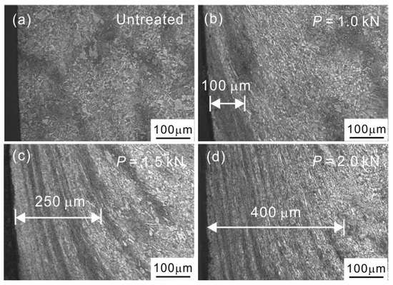
Figure 1.
Cross-sectional metallographic observations of (a) the untreated specimen and ultrasonic surface rolling processing (USRP) specimens treated at a static load of (b) 1.0 kN, (c) 1.5 kN and (d) 2.0 kN. The distance between the white lines represents the thickness of the deformation layer near the surface of the USRP specimens.
The morphology evolution on the specimen surfaces before and after USRP is shown in Figure 2. The untreated specimen is subjected to a turning process using the lathe. Large amounts of parallel lines with peak and valley features emerge on the untreated specimen surface, which are the result of machine processing. The surface roughness, Ra, termed as the arithmetical mean deviation of the profile, is measured to be as large as ~0.92 μm for this state, as displayed in Figure 3. After applying USRP on the specimen surface, the “peak” material is squeezed into the “valley” region under the action of the high-frequency dynamic impact and static load [23,27]. The machining marks of the specimen surface will be eliminated. It is seen that a smooth surface without remarkable machining marks was formed under a static load of 1.0 kN. The Ra value of this state was greatly reduced to ~0.12 μm, ~87% lower than that of the untreated specimen.

Figure 2.
Surface morphologies in (a) the untreated specimen and (b–d) the USRP-treated specimens with a static load P of 1.0 kN, 1.5 kN and 2.0 kN, respectively.
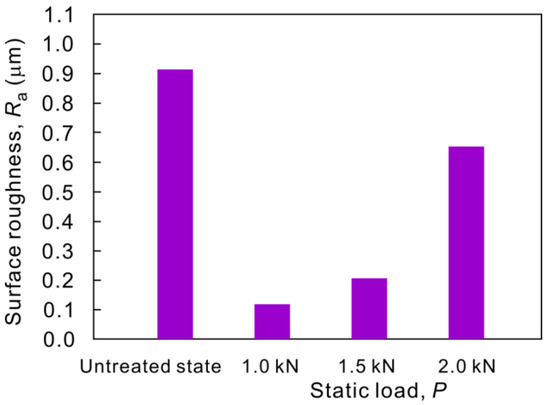
Figure 3.
Surface roughnesses Ra of untreated and USRP-treated specimens with different static loads P. The Ra is the average value of several measurements.
Under a static load of 1.5 kN, a scale-like feature was observed on the specimen surface, as shown in Figure 2c. When further increasing the static load to 2.0 kN, the size of the scale-like unit became larger and its boundary became more unambiguous (Figure 2d). The emergence of the scale-like feature caused a poor surface quality. The values of Ra for the two static loads were increased to be ~0.21 μm and ~0.65 μm (Figure 3), respectively, in agreement with the surface features. Despite the fact that the values of Ra in the specimen under a static load of 1.5 kN and 2.0 kN were still lower than that of the untreated specimen, the value of Ra showed an increasing trend as the static load increased. The variation of the Ra value with the static load was consistent with the results reported by Wu et al. [35], who also found that the over static load would destroy the surface during USRP. The poor surface quality was mainly ascribed to the severe plastic deformation of the surface material when applying the over static load. Besides, the over static load probably makes the treatment processing unstable, further deteriorating the surface quality.
The micro–Vickers hardness distribution along the cross section of the untreated specimen and different USRP specimens was measured, as depicted in Figure 4. It is seen that the microhardness of the untreated state nearly remained constant, ~222 HV, despite the depth. The relationship between the microhardness and the depth for the three static loads of USRP exhibited a similar variation trend, i.e., the microhardness firstly decreased when increasing the depth away from the surface, and then reached a constant value. The values of the vertical intercept, which represents the maximum microhardness on the surface, were ~304 HV, ~324 HV and ~332 HV, respectively, for static loads of 1.0 kN, 1.5 kN and 2.0 kN. The constant value was nearly equal to that of the untreated one. The above result indicates that the microhardness in the near-surface/surface region was enhanced after USRP, relative to the untreated one, and increased with an increasing static load. We also obtained the thickness of the hardening layer after USRP by measuring the abscissa value of the curve knee in Figure 4. The thicknesses of the hardening layer for the three static loads were determined to be ~386 μm, ~447 μm and ~509 μm, respectively, which was consistent with the variation trend of the thickness of the deformation layer. The larger static load led to the formation of a thicker hardening layer. It is noted that the thickness of the deformation layer was measured by optical microscope. The resolution of the optical microscope was not large enough to observe the nano-scale and submicron-scale deformed microstructure. This induced the fact that the measured thickness of the deformation layer seemed to be lower than the thickness of the hardening layer for the three static loads.
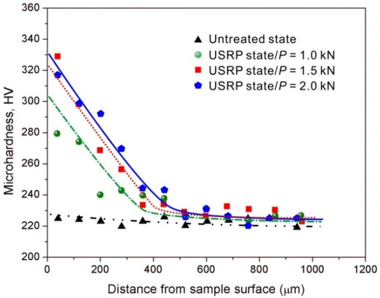
Figure 4.
Microhardness distribution along the cross section of the untreated specimen and USRP-treated specimens with different static loads P.
The enhanced hardness in the near-surface layer after USRP is mainly attributed to multiple dislocations and microstructure refinement [21,36]. It is reported that the strength σf can be theoretically estimated as [37]:
where σ0 is the friction strength, k is the Hall–Petch constant, dfp is the mean free path for dislocations, α is a constant, G is the shear modulus, b is the Burgers vector and ρ is the dislocation density. The above equation indicates that the material strength or hardness increases when increasing the dislocation density and decreasing the grain size. The USRP induces a severe plastic deformation, and produces a high-density dislocation structure and large area of grain boundaries in the near-surface region. These microstructure characteristics will improve the resistance to dislocation slipping and eventually enhance the material microhardness after USRP when compared with the untreated specimen.
The results of the surface residual stress of the specimens before and after USRP treatment are presented in Figure 5. The surface residual stress of the untreated specimen was compressive, ~228 MPa, probably due to the machining process. After USRP under a static load of 1.0 kN, the surface compressive residual stress was largely enhanced to ~625 MPa, which was three times as high as for the untreated specimen. As the static load increased to 1.5 kN and 2.0 kN, the surface compressive residual stresses were further enhanced to ~690 MPa and ~739 MPa, respectively, indicating that an increase of the static load promoted the enhancement of the surface compressive residual stress. The generation and increase of the surface compressive residual stress is related to the severe plastic deformation induced by USRP [27]. When applying a high-frequency vibration and static load on the specimen surface, the surface layer and the layer below it will be subjected to different stress levels. This results in varying plastic strains in different layers. The mismatching of plastic deformation will produce the compressive residual stress on the surface. Besides, the high-density dislocations in the near-surface layer cause the distortion of the atomic lattice, further enlarging the compressive residual stress.
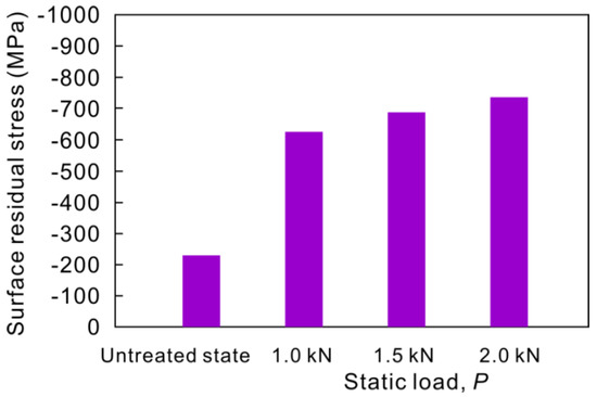
Figure 5.
Surface residual stress of the untreated and USRP-treated specimens with different static loads P. The surface residual stress is the average value of several measurements.
The current experimental results on the static-load effect on compressive residual stress are in agreement with the theoretical calculations and simulations in previous investigations [38,39,40,41,42]. The finite element (FE) simulation reported by Khan et al. [38] indicated that a higher force produced a larger compressive residual stress after USRP. Then, a 3D dynamic FE model for the USRP process was developed by Liu et al. [40], which further confirmed that increasing the static load could greatly enhance the magnitude of compressive residual stress. Recently, Zhang et al. [41] built a theoretical model of the compressive residual stress field based on the combination of FE simulation and elastic-plastic contact theory, and found that the beneficial effect of the static load on the compressive residual stress was essentially attributed to the variation of the plastic contact radius.
3.2. Fatigue Endurance Limits of Untreated and USRP-Treated Specimens
As indicated above, the larger static load induces the increase of surface roughness, which may deteriorate the fatigue property; on the other hand, a larger static load enhances the microhardness and compressive residual stress, which may be beneficial for the fatigue property. For a comprehensive consideration of surface roughness, microhardness and compressive residual stress, an intermediate static load state of 1.5 kN was selected to conduct the fatigue test. The staircase diagrams of the specimens before and after USRP with a static load of 1.5 kN are shown in Figure 6. By pairing the fractured and non-fractured specimens under the adjacent stress levels, the fatigue endurance limit σ−1 can be calculated as follows:
where m is the experimental number, i is the order number of stress levels, n is the number of stress levels, σi is the stress level and Vi is the experimental number under σi. According to Equation (2), the 107 fatigue endurance limits for these two states were measured to be ~352 MPa and ~401 MPa. It was found that the fatigue limit was enhanced by ~14% after USRP with a static load of 1.5 kN, which indicated the validity of USRP in improving the fatigue property.
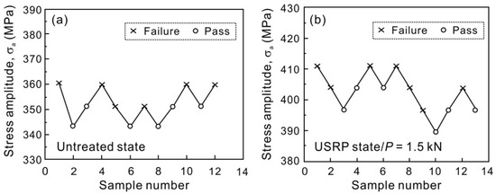
Figure 6.
Staircase diagram of the specimens in (a) the untreated state and (b) the USRP state with a static load P of 1.5 kN.
The fatigue limit represents the stress for fatigue crack initiation. The enhancement of the fatigue endurance limit induced by USRP is mainly explained through the following factors, based on the perspective of fatigue crack initiation:
(1) Grain refinement and work-hardening. The microstructural refinement in the plastic deformation layer near the surface of the USRP specimen has been shown in Figure 1. To investigate the difference of the fatigue limits between the untreated and USRP specimen with a static load of 1.5 kN we further observed the near-surface microstructural features of these two states by TEM, as shown in Figure 7. Relative to the untreated one, many elongated ultra-fine grains with a width under ~500 nm could be seen in the USRP specimen. The grain refinement was also supported by the result of the selected area electron diffraction (SEAD) pattern, which showed the obvious diffusive diffraction spots. Besides, it was clear that a high density of dislocation lines, dislocation tangles and dislocation walls were formed in the grain, as marked by the arrows in Figure 7b. The grain refinement, as well as the dislocation structure, agreed well with the microstructure observation of the deformation layer after SPD [14,20,43,44]. The mechanism of grain refinement can be explained through dislocation motion [24,31]. For the current material, the main plastic deformation mode was dislocation slipping. As the strain increases, the dislocations within the original grains are largely produced and proliferated. To reduce the system energy, the denser dislocations will slip, accumulate, interact and rearrange, eventually leading to the formation of dislocation tangles, walls and cells. These dislocation characteristics gradually break the original grain and transform into the sub-grain boundaries. When further increasing the strain, the sub-grain boundaries turn into grain boundaries with small or big angles. The original grain is subdivided into several small-sized grains. The small-sized grains become stable, until the generating and annihilating rates of dislocations reach an equilibrium state. Thus, the dislocation operation is responsible for the grain refinement in the near-surface layer after USRP.

Figure 7.
Transmission electron microscope (TEM) micrographs of (a) the untreated specimen and (b) USRP specimen with a static load of 1.5 kN at a depth of ~100 μm from the surface. The corresponding selected area electron diffraction (SAED) pattern was obtained from the USRP specimen.
The mechanism of fatigue crack initiation in metallic materials has been known [9,45]. Local dislocations activate and slip along the favorably oriented slip plane in the grain under cyclic loading, eventually leading to the formation of persistent slip bands (PSBs) on the specimen surface. The continuous slipping of PSBs will generate the extrusion and intrusion. Fatigue cracks are prone to initiate from the stress concentrators. Once the specimen surface is treated by USRP, larger amounts of dislocation lines, tangles and walls are introduced inside the surface layer. The high-density dislocation structure prevents the dislocation slipping and thereby suppresses the fatigue crack origination from slipping. On the other hand, the USRP refines the original grains into many small-sized grains. As a result, the area of the grain boundary will be greatly increased. These grain boundaries provide the obstacle for dislocation slipping, further preventing the initiation of fatigue cracks [32]. Besides, the surface work-hardening (see Figure 4) induced by the dense dislocation structure and refined grains also increases the slipping resistance and then provides a beneficial effect for arresting the fatigue crack initiation [46].
(2) Surface roughness. The fatigue crack tends to initiate from the casting and processing defects, such as inclusion, pore, scratch, etc. [11,47]. In the untreated specimen, large amounts of machining marks serve as the local stress concentration sites and are potentially the sources for fatigue crack initiation. This will accelerate the occurrence of fatigue damage. The USRP can effectively remove these processing marks, thus resulting in a decreased surface roughness, as mentioned above in Figure 3. The better surface quality delays the initiation of fatigue cracks.
(3) Compressive residual stress. For the fatigued specimen after USRP treatment (see Figure 5), a portion of the applied tensile stress is balanced by the compressive residual stress, and then the applied tensile stress in the near-surface region is decreased [13,18]. This induces the fatigue crack initiation inside the specimen, rather than from the surface, delaying the initiation of the fatigue crack. The effect of compressive residual stress caused by different SPD methods on the fatigue property of various materials has been extensively studied using experiments and simulations, and the results verify the important role of compressive residual stress in the enhancement of fatigue property [48,49,50].
For a comprehensive understanding of enhanced fatigue property induced by the USRP treatment, the schematic diagram of the USRP effect on specimen surface is plotted, as shown in Figure 8. The beneficial effect of USRP on the fatigue limit of the current axle steel is attributed to the synergistic effect of the refined microstructure, increased surface hardness, reduced surface roughness and high level of compressive residual stress by this surface treatment method, which causes a positive influence in retarding the fatigue crack initiation.
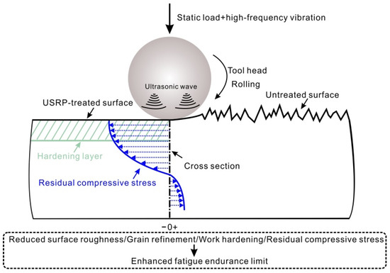
Figure 8.
Schematic illustration of plastic deformation after USRP treatment.
3.3. Comparison of Fatigue Characteristics of the Rolling Specimen and USRP Specimen
During the USRP process, the high-frequency vibration and static-load rolling are simultaneously applied on the material’s surface by a scrollable tool head. In order to differentiate the role of the dynamic impact and rolling in the surface treatment and to further understand the effect of USRP on the fatigue property, the fatigue endurance limit of the rolling specimen was measured and compared with that of the USRP specimen with a static load of 1.5 kN. We note that the rolling specimen was surface-treated using the identical equipment when turning off the ultrasonic system. The staircase diagram of the specimen after rolling is shown in Figure 9. Based on Equation (2), the fatigue limit of the rolling specimen under a static load of 1.5 kN was calculated to be ~386 MPa, which was lower than that of the USRP specimen, ~401 MPa. One can see that the introduction of the ultrasonic impact could improve the fatigue limit by ~4% when compared with the rolling specimen. The enhancement of the fatigue limit was clarified by the comparison of the microstructure, surface roughness, microhardness and residual stress between the rolling and USRP states, as follows.
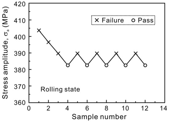
Figure 9.
Staircase diagram of the specimen in the rolling state with a static load of 1.5 kN.
Figure 10a presents the cross-sectional microstructure of the specimen after rolling. The macroscopic morphology of the rolling specimen is similar to that of the USRP specimen (Figure 1c), i.e., there exists an obvious plastic deformation layer with the flow marks near the specimen surface. The thickness of the deformation layer after rolling was measured to be ~200 μm, which is obviously lower than that of the USRP specimen, ~250 μm. The larger deformation thickness induced by USRP indicates that the high-frequency vibration has an important role in treating the surface microstructure.
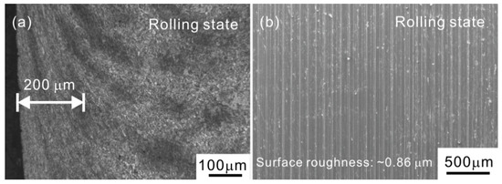
Figure 10.
(a) Optical micrograph of the cross-section and (b) scanning electron microscope (SEM) observation of the surface morphology in the specimen with the rolling state.
We observed the surface morphology of the rolling specimen, as shown in Figure 10b. It is seen that the specimen surface after rolling is covered with the parallel marks. The rough feature is probably caused by the friction between the tool head and specimen surface. The value of the surface roughness Ra of the rolling specimen was measured to be ~0.86 μm, which is close to that of the machining specimen (~0.92 μm) but much higher than that of the USRP specimen (~0.21 μm). It seems that the rolling has a weak effect in decreasing the roughness and improving the surface quality. The modified surface quality after USRP mainly derives from the role of the high-frequency impact on the surface.
The microhardness distribution along the cross section of the specimens after rolling and USRP is presented in Figure 11. For these two states, the microhardness firstly decreased and then remained constant when increasing the depth from the specimen surface. The microhardness of the USRP specimen in the near-surface region was higher than that of the rolling specimen. In particular, the maximum microhardness on the surface after USRP was enhanced by as much as ~11% relative to the rolling specimen. Besides, the thickness of the hardening layer in the USRP specimen was ~447 μm, which was also larger than that of the rolling specimen, ~378 μm. Based on the above result, it is found that the high-frequency impact can further promote the hardening ability on the basis of rolling.

Figure 11.
Microhardness distribution along the cross-section of rolling and USRP-treated specimens with a static load P of 1.5 kN.
The variation of the residual stress from the surface toward the interior in the rolling and USRP specimens is shown in Figure 12. Both the rolling and USRP treatments were found to produce a deep layer of compressive residual stress. The residual stress increased to the maximum compressive value and then decreased when increasing the depth from the surface, finally changing to a tensile state. The distribution of compressive residual stress with the depth after rolling and USRP is consistent with the previous results in the SPD methods [32,51]. For the current two states, the maximum compressive stress is located at a depth of ~50 μm but not at the surface, which is caused by the heat effect induced by the high-frequency impact, high strain rate and low thermal conductivity on the surface [52]. Another reason for the maximum value is that the area of maximum shear stress is located in the subsurface, based on the Hertz contact model [53].

Figure 12.
Residual stress distribution along the cross-section of the rolling and USRP-treated specimens with a static load P of 1.5 kN.
The value of the maximum compressive residual stress of the USRP specimen was measured to be ~823 MPa, ~31% higher than that of the rolling specimen, ~628 MPa. The depths of the compressive residual stress fields for these two states could be also obtained, and they were ~684 μm for the USRP state and ~381 μm for the rolling state. The comparison of the compressive residual stress between the rolling and USRP specimens demonstrated the important role of the high-frequency impact in improving the surface property of the compressive residual stress. The beneficial effect of the high-frequency impact was also supported by the theoretical analysis model based on the FE simulation, which showed that the high-frequency vibration energy and the static force simultaneously applied to the surface could considerably increase the distribution of the compressive residual stress field, compared with only the static force [41].
Based on the above results, it can be concluded that the surface properties after USRP, including the surface roughness, microhardness and compressive residual stress, as well as the microstructure, are superior to those after rolling. This shows the effectiveness of an impact with a high frequency in improving the microstructure and surface property. The better microstructure and surface property induced by USRP than the only rolling have a beneficial effect in preventing the fatigue crack initiation, which eventually results in a larger fatigue endurance limit.
4. Conclusions
We performed a systematic investigation of the effect of USRP on the surface characteristics and fatigue properties of EA4T axle steel used in high speed trains, and the USRP was proven to be an effective surface treatment method to improve the surface and fatigue properties of axle steel. The detailed conclusions are listed as follows:
- (1)
- The surface microstructure and characteristics of EA4T axle steel can be modified by USRP treatment. The results indicate that the USRP specimen possesses a refined surface microstructure, reduced surface roughness, enhanced surface microhardness and residual compressive stress when compared with an untreated specimen, which is due to the severe plastic deformation in the near-surface region.
- (2)
- The influence of the static load on the surface characteristics of axle steel was investigated. When increasing the static load, the surface microhardness and compressive residual stress are enhanced, while the surface roughness is also increased.
- (3)
- The fatigue endurance limit of USRP axle steel under a static load of 1.5 kN is enhanced significantly when compared with an untreated one. The enhancement of the fatigue limit from ~352 MPa to ~401 MPa after USRP is attributed to the synergistic effect of the decreased surface roughness, increased surface hardness and compressive residual stress, as well as the refined microstructure.
- (4)
- The fatigue endurance limits between the rolling and USRP axle steels under a static load of 1.5 kN were compared. An increment of ~4% was achieved after USRP, relative to the rolling. This verifies that the role of the high-frequency vibration could enhance the fatigue properties.
Author Contributions
Conceptualization, G.L. and X.R.; Methodology, X.R.; Validation, P.L. and X.W.; Formal Analysis, L.C. and X.W.; Investigation, L.C. and P.L.; Resources, L.C. and X.R.; Data Curation, L.C. and X.W.; Visualization, L.C. and X.W.; Supervision, G.L. and X.R.; Writing—Original Draft preparation, X.W.; Writing—Review and Editing, X.R.; Funding Acquisition, X.W. and X.R. All authors have read and agreed to the published version of the manuscript.
Funding
This work was financially supported by the National Natural Science Foundation of China (NSFC) under Grant Nos. 11932020, the China Postdoctoral Science Foundation (2019M660455) and the Fundamental Research Funds for the Central Universities (FRF-TP-19-011A1).
Conflicts of Interest
The authors declare no conflict of interest.
References
- Stephens, R.I.; Fatemi, A.; Stephens, R.R.; Fuchs, H.O. Metal Fatigue in Engineering; John Wiley and Sons: New York, NY, USA, 2001. [Google Scholar]
- Schütz, W. A history of fatigue. Eng. Fract. Mech. 1996, 54, 263–300. [Google Scholar] [CrossRef]
- Meyers, M.A.; Chawla, K.K. Mechanical Behavior of Materials; Cambridge University Press: Cambridge, UK, 2008. [Google Scholar]
- Miller, M.; Liaw, P.K. Bulk Metallic Glasses: An Overview; Springer Science and Business Media: New York, NY, USA, 2008. [Google Scholar]
- Regazzi, D.; Cantini, S.; Cervello, S.; Foletti, S.; Pourheidar, A.; Beretta, S. Improving fatigue resistance of railway axles by cold rolling: Process optimisation and new experimental evidences. Int. J. Fatigue 2020, 137, 105603. [Google Scholar] [CrossRef]
- Beretta, S.; Ghidini, A.; Lombardo, F. Fracture mechanics and scale effects in the fatigue of railway axles. Eng. Fract. Mech. 2005, 72, 195–208. [Google Scholar] [CrossRef]
- Zerbst, U.; Beretta, S.; Köhler, G.; Lawton, A.; Vormwald, M.; Beier, H.T.; Klinger, C.; Cerny, I.; Rudlin, J.; Heckel, T.; et al. Safe life and damage tolerance aspects of railway axles—A review. Eng. Fract. Mech. 2013, 98, 214–271. [Google Scholar] [CrossRef]
- Smith, R.A.; Hillmansen, S. A brief historical overview of the fatigue of railway axles. Proc. Inst. Mech. Eng. Part F J. Rail Rapid Transit. 2004, 218, 267–277. [Google Scholar] [CrossRef]
- Basinski, Z.S.; Basinski, S.J. Formation and growth of subcritical fatigue cracks. Scr. Metall. 1984, 18, 851–856. [Google Scholar] [CrossRef]
- Zhang, Z.F.; Wang, Z.G. Grain boundary effects on cyclic deformation and fatigue damage. Prog. Mater. Sci. 2008, 53, 1025–1099. [Google Scholar] [CrossRef]
- Pang, J.C.; Li, S.X.; Wang, Z.G.; Zhang, Z.F. General relation between tensile strength and fatigue strength of metallic materials. Mater. Sci. Eng. A 2013, 564, 331–341. [Google Scholar] [CrossRef]
- Zhao, X.H.; Sun, Z.Y.; Xu, D.S.; Liu, Y. Local fatigue strength evaluation of shot peened 40Cr notched steel. Metals 2018, 8, 681. [Google Scholar] [CrossRef]
- Tekeli, S. Enhancement of fatigue strength of SAE 9245 steel by shot peening. Mater. Lett. 2002, 57, 604–608. [Google Scholar] [CrossRef]
- Lou, S.; Li, Y.; Zhou, L.; Nie, X.; He, G.; Li, Y.; He, W. Surface nanocrystallization of metallic alloys with different stacking fault energy induced by laser shock processing. Mater. Des. 2016, 104, 320–326. [Google Scholar] [CrossRef]
- Zhang, Y.K.; Lu, J.Z.; Ren, X.D.; Yao, H.B.; Yao, H.X. Effect of laser shock processing on the mechanical properties and fatigue lives of the turbojet engine blades manufactured by LY2 aluminum alloy. Mater. Des. 2009, 30, 1697–1703. [Google Scholar] [CrossRef]
- Liang, Y.L.; Wang, Z.B.; Zhang, J.; Zhang, J.B.; Lu, K. Enhanced bonding property of cold-sprayed Zn-Al coating on interstitial-free steel substrate with a nanostructured surface layer. Appl. Surf. Sci. 2016, 385, 341–348. [Google Scholar] [CrossRef]
- Pandey, V.; Chattopadhyay, K.; Srinivas, N.C.S.; Singh, V. Role of ultrasonic shot peening on low cycle fatigue behavior of 7075 aluminium alloy. Int. J. Fatigue 2017, 103, 426–435. [Google Scholar] [CrossRef]
- Suh, C.M.; Song, G.H.; Suh, M.S.; Pyoun, Y.S. Fatigue and mechanical characteristics of nanostructured tool steel by ultrasonic cold forging technology. Mater. Sci. Eng. A 2007, 443, 101–106. [Google Scholar] [CrossRef]
- Bagherifard, S.; Guagliano, M. Fatigue behavior of a low-alloy steel with nanostructured surface obtained by severe shot peening. Eng. Fract. Mech. 2012, 81, 56–68. [Google Scholar] [CrossRef]
- Mordyuk, B.N.; Prokopenko, G.I.; Volosevich, P.Y.; Matokhnyuk, L.E.; Byalonovich, A.V.; Popova, T.V. Improved fatigue behavior of low-carbon steel 20GL by applying ultrasonic impact treatment combined with the electric discharge surface alloying. Mater. Sci. Eng. A 2016, 659, 119–129. [Google Scholar] [CrossRef]
- Liu, D.; Liu, D.X.; Zhang, X.H.; Liu, C.S.; Ao, N. Surface nanocrystallization of 17-4 precipitation-hardening stainless steel subjected to ultrasonic surface rolling process. Mater. Sci. Eng. A 2018, 726, 69–81. [Google Scholar] [CrossRef]
- Zhang, Q.L.; Hu, Z.Q.; Su, W.W.; Zhou, H.L.; Liu, C.X.; Yang, Y.L.; Qi, X.W. Microstructure and surface properties of 17-4PH stainless steel by ultrasonic surface rolling technology. Surf. Coat. Technol. 2017, 321, 64–73. [Google Scholar] [CrossRef]
- Lu, L.X.; Sun, J.; Li, L.; Xiong, Q.C. Study on surface characteristics of 7050-T7451 aluminum alloy by ultrasonic surface rolling process. Int. J. Adv. Manuf. Technol. 2016, 87, 2533–2539. [Google Scholar] [CrossRef]
- Wang, T.; Wang, D.P.; Liu, G.; Gong, B.M.; Song, N.X. Investigations on the nanocrystallization of 40Cr using ultrasonic surface rolling processing. Appl. Surf. Sci. 2008, 255, 1824–1829. [Google Scholar]
- Wang, H.B.; Song, G.L.; Tang, G.Y. Effect of electropulsing on surface mechanical properties and microstructure of AISI 304 stainless steel during ultrasonic surface rolling process. Mater. Sci. Eng. A 2016, 662, 456–467. [Google Scholar] [CrossRef]
- Wang, H.B.; Song, G.L.; Tang, G.Y. Enhanced surface properties of austenitic stainless steel by electropulsing-assisted ultrasonic surface rolling process. Surf. Coat. Technol. 2015, 282, 149–154. [Google Scholar] [CrossRef]
- Ye, H.; Sun, X.; Liu, Y.; Rao, X.X.; Gu, Q. Effect of ultrasonic surface rolling process on mechanical properties and corrosion resistance of AZ31B Mg alloy. Surf. Coat. Technol. 2019, 372, 288–298. [Google Scholar] [CrossRef]
- Ao, N.; Liu, D.X.; Liu, C.S.; Zhang, X.H.; Liu, D. Face-centered titanium induced by ultrasonic surface rolling process in Ti-6Al-4V alloy and its tensile behavior. Mater. Charact. 2018, 145, 527–533. [Google Scholar] [CrossRef]
- Wang, Z.; Xiao, Z.Y.; Huang, C.S.; Wen, L.P.; Zhang, W.W. Influence of ultrasonic surface rolling on microstructure and wear behavior of selective laser melted Ti-6Al-4V alloy. Materials 2017, 10, 1203. [Google Scholar] [CrossRef]
- Lai, F.Q.; Qu, S.G.; Lewis, R.; Slatter, T.; Fu, W.L.; Li, X.Q. The influence of ultrasonic surface rolling on the fatigue and wear properties of 23-8N engine valve steel. Int. J. Fatigue 2019, 125, 299–313. [Google Scholar] [CrossRef]
- Li, G.; Qu, S.G.; Pan, Y.X.; Li, X.Q. Effects of the different frequencies and loads of ultrasonic surface rolling on surface mechanical properties and fretting wear resistance of HIP Ti-6Al-4V alloy. Appl. Surf. Sci. 2016, 389, 324–334. [Google Scholar] [CrossRef]
- Liu, C.S.; Liu, D.X.; Zhang, X.H.; He, G.Y.; Xu, X.C.; Ao, N.; Ma, A.; Liu, D. On the influence of ultrasonic surface rolling process on surface integrity and fatigue performance of Ti-6Al-4V alloy. Surf. Coat. Technol. 2019, 370, 24–34. [Google Scholar] [CrossRef]
- British Standard. BS EN 13261: 2009 + A1: 2010, Railway Application-Wheelsets and Bogies-Axles-Product Requirements; European Committee for Standardization Management Centre: Brussels, Belgium, 2010. [Google Scholar]
- Little, R.E.; Jebe, E.H. Statistical Design of Fatigue Experiments; Wiley: New York, NY, USA, 1975. [Google Scholar]
- Wu, B.; Zhang, J.X.; Zhang, L.J.; Pyoun, Y.S.; Murakami, R. Effect of ultrasonic nanocrystal surface modification on surface and fatigue properties of quenching and tempering S45C steel. Appl. Surf. Sci. 2014, 321, 318–330. [Google Scholar] [CrossRef]
- Cao, X.J.; Pyoun, Y.S.; Murakami, R. Fatigue properties of a S45C steel subjected to ultrasonic nanocrystal surface modification. Appl. Surf. Sci. 2010, 256, 6297–6303. [Google Scholar] [CrossRef]
- Ye, C.; Telang, A.; Gill, A.S.; Suslov, S.; Idell, Y.; Zweiacker, K.; Wiezorek, J.M.K.; Zhou, Z.; Qian, D.; Mannava, S.R.; et al. Gradient nanostructure and residual stresses induced by Ultrasonic Nano-crystal Surface Modification in 304 austenitic stainless steel for high strength and high ductility. Mater. Sci. Eng. A 2014, 613, 274–288. [Google Scholar] [CrossRef]
- Khan, M.K.; Fitzpatrick, M.E.; Wang, Q.Y.; Pyoun, Y.S.; Amanov, A. Effect of ultrasonic nanocrystal surface modification on residual stress and fatigue cracking in engineering alloys. Fatigue Fract. Eng. Mater. Struct. 2018, 41, 844–855. [Google Scholar] [CrossRef]
- Liu, Y.; Wang, L.J.; Wang, D.P. Finite element modeling of ultrasonic surface rolling process. J. Mater. Proc. Technol. 2011, 211, 2106–2113. [Google Scholar] [CrossRef]
- Liu, Y.; Wang, L.J.; Wang, D.P. Study on ultrasonic surface rolling process using FEM analysis. Adv. Mater. Res. 2011, 189–193, 2112–2115. [Google Scholar] [CrossRef]
- Zhang, M.; Zhang, Y.X.; Zhou, Y. Theoretical and experimental analysis of compressive residual stress field on 6061 aluminum alloy after ultrasonic surface rolling process. J. Mech. Eng. Sci. 2019, 233, 5363–5376. [Google Scholar]
- Zhang, M.; Liu, Z.H.; Deng, J.; Yang, M.J.; Dai, Q.L.; Zhang, T.Z. Optimum design of compressive residual stress field caused by ultrasonic surface rolling with a mathematical model. Appl. Math. Mod. 2019, 76, 800–831. [Google Scholar] [CrossRef]
- Liu, Y.; Zhao, X.H.; Wang, D.P. Determination of the plastic properties of materials treated by ultrasonic surface rolling process through instrumented indentation. Mater. Sci. Eng. A 2014, 600, 21–31. [Google Scholar] [CrossRef]
- Zhou, L.; Liu, G.; Ma, X.L.; Lu, K. Strain-induced refinement in a steel with spheroidal cementite subjected to surface mechanical attrition treatment. Acta Mater. 2008, 56, 78–87. [Google Scholar] [CrossRef]
- Chan, K.S. Roles of microstructure in fatigue crack initiation. Int. J. Fatigue 2010, 32, 1428–1447. [Google Scholar] [CrossRef]
- Nalla, R.K.; Altenberger, I.; Noster, U.; Liu, G.Y.; Scholtes, B.; Ritchie, R.O. On the influence of mechanical surface treatments-deep rolling and laser shock peening-on the fatigue behavior of Ti-6Al-4V at ambient and elevated temperatures. Mater. Sci. Eng. A 2003, 355, 216–230. [Google Scholar] [CrossRef]
- Wang, M.; Xiao, W.; Gan, P.; Gu, C.; Bao, Y.P. Study on inclusions distribution and cyclic fatigue performance of gear steel 18CrNiMo7-6 forging. Metals 2020, 10, 201. [Google Scholar] [CrossRef]
- Peyre, P.; Fabbro, R.; Merrien, P.; Lieurade, H.P. Laser shock processing of aluminium alloys. Application to high cycle fatigue behavior. Mater. Sci. Eng. A 1996, 210, 102–113. [Google Scholar] [CrossRef]
- Altenberger, I.; Nalla, R.K.; Sano, Y.; Wagner, L.; Ritchie, R.O. On the effect of deep-rolling and laser-peening on the stress-controlled low- and high-cycle fatigue behavior of Ti-6Al-4V at elevated temperatures up to 550 °C. Int. J. Fatigue 2012, 44, 292–302. [Google Scholar] [CrossRef]
- Cheng, M.L.; Zhang, D.Y.; Chen, H.W.; Qin, W.; Li, J.S. Surface nanocrystallization and its effect on fatigue performance of high-strength materials treated by ultrasonic rolling process. Int. J. Adv. Manuf. Technol. 2016, 83, 123–131. [Google Scholar]
- Oevermann, T.; Wegener, T.; Niendorf, T. On the evolution of residual stresses, microstructure and cyclic performance of high-manganese austenitic TWIP-steel after deep rolling. Metals 2019, 9, 825. [Google Scholar] [CrossRef]
- Zhang, X.C.; Zhang, Y.K.; Lu, J.Z.; Xuan, F.Z.; Wang, Z.D.; Tu, S.T. Improvement of fatigue life of Ti-6Al-4V alloy by laser shock peening. Mater. Sci. Eng. A 2010, 527, 3411–3415. [Google Scholar] [CrossRef]
- Zhao, W.D.; Liu, D.X.; Zhang, X.H.; Zhou, Y.; Zhang, R.X.; Zhang, H.; Ye, C. Improving the fretting and corrosion fatigue performance of 300M ultrahigh strength steel using the ultrasonic surface rolling process. Int. J. Fatigue 2019, 121, 30–38. [Google Scholar] [CrossRef]
© 2020 by the authors. Licensee MDPI, Basel, Switzerland. This article is an open access article distributed under the terms and conditions of the Creative Commons Attribution (CC BY) license (http://creativecommons.org/licenses/by/4.0/).