Article

Phase Equilibrium Diagram for Electric Arc Furnace Slag Optimization in High Alloyed Chromium Stainless Steelmaking

1
Thermal Process Engineering, University of Bayreuth, Universitätsstrasse 30, D-94557 Bayreuth, Germany
2
Department of Materials Science and Engineering, Seoul National University, 1 Gwanak-ro, Gwanak-Gu, Seoul 08826, Korea
3
RHI MAGNESITA, Magnesitstrasse 2, A-9700 Leoben, Austria
*
Author to whom correspondence should be addressed.
Metals 2020, 10(6), 826; https://doi.org/10.3390/met10060826
Submission received: 25 May 2020 / Revised: 16 June 2020 / Accepted: 18 June 2020 / Published: 20 June 2020

Abstract

:
The electric arc furnace (EAF) process for steelmaking of Cr and Ni high alloyed stainless steel grades differs significantly from the steelmaking process of carbon steel due to the special raw materials and generally lower oxygen consumption. The special slag chemistry in the EAF process affects slag foaming and refractory wear characteristics due to an increased content of CrOx. A special slag diagram is presented in order to improve monitoring and control of slag compositions for Cr alloyed heats, with special focus on saturation to MgO periclase and dicalcium silicate C2S in order to minimize MgO losses from the refractory lining and to improve slag refining capability by avoidance of stable C2S. With the same diagram different EAF process strategies can be efficiently monitored, either at elevated CaO and basicity with lower spinel concentration and more liquid process slags near C2S saturation or at lower CaO content and basicity with increased spinel concentration and stiffer slags at MgO saturation but certainly no C2S stability. Examples for three industrial EAFs are given.

1. Introduction

Some 52.2 million tons of high alloyed and stainless steel grades were produced in 2019, i.e., approximately 2.8% of total steel production with an increasing trend due to global market demands. The modern production process is based on melting of steel scrap and alloys in an electric arc furnace (EAF) and subsequent decarburization and refinement of the molten metal in an argon-oxygen decarburization (AOD) converter or more rarely by vacuum oxygen decarburization (VOD) treatment. In a few cases, raw steel is melted from scrap in the EAF and liquid or solid Cr-alloys are added at the converter.
Production of high-alloyed Cr or Cr-Ni molten metal in the EAF introduces additional metallurgical constraints to EAF process conditions. As oxidation of C and Cr in the molten metal occurs at very similar oxygen activities, special care is needed to minimize Cr losses, especially during oxygen injection in the EAF. Cr oxidation increases at depleted C concentration. The amount of injected oxygen in the EAF is usually lower than 15 m3/t compared to levels of between 25 and 40 m3/t for EAF carbon steelmaking, and up to 50 m3/t for hot metal refining in LD converters. As consequence, the mixing of the steel melt in the EAF is insufficient and concentration gradients of C, Si and Cr may occur in the melt volume. Temperature gradients caused by low bath movement and formation of (Mn,Mg)Cr2O4 spinels may contribute to unwanted bottom build-up of the EAF hearth. Active mixing of the melt volume by inert gas bottom stirring or electromagnetic stirring is state-of-the art for the majority of EAFs for stainless steel grades.
The ratio of the relevant Cr oxides in the slag, CrO and Cr2O3, depends on temperature and oxygen partial pressure. In this paper, we use Cr2O3 as a synonym for both Cr oxides in the slag, due to the dominance of Cr2O3 species at low oxygen partial pressure in the molten metal. An option to control Cr oxidation and to decrease Cr losses in the EAF is by keeping elevated C and Si levels in the steel melt by decreased oxygen injection [1] and mixing of the steel melt with the Cr2O3-bearing slag during tapping. High slag basicity, and pronounced mixing dynamics during tapping via spout is known to improve Cr2O3 reduction [2]. In case of elevated final Cr2O3 concentrations, reducing agents as FeSi, C, or Al may be added before tapping in order further reduce Cr2O3 and to liquefy the oversaturated stiff slag by lowering the basicity of slag. Procedures for the optimum Cr recovery are still under discussion. For example, the combination of FeSi and carbon as reducing agents have been shown the best results on final Cr2O3 content of the slag [3]. Mees, however, found best efficiency of Cr2O3 reduction with Al addition [4]. In the 2-step (duplex) stainless steelmaking process, the remaining carbon levels after EAF tapping are further decreased in the AOD converter by submerged injection of oxygen, which is later diluted with inert gases in order to control formation of Cr2O3 by lowering oxygen activity in the steel melt and slag. In the VOD, decarburization at controlled Cr2O3 formation is achieved by inert gas stirring at decreased atmosphere pressure.
The Cr2O3 levels in the EAF slag affect significantly the process conditions: due to the low Cr2O3 solubility in basic EAF slag, the precipitation of Cr2O3-bearing solids occurs and results in an increase of effective slag viscosity. High slag viscosity and lower amounts of CO gas due to restricted oxygen injection inhibit efficient slag foaming [1]. Chosen slag composition is often at basicity (CaO/SiO2) < 1.5 in order to increase Cr2O3 activity, but optimum basicity for foaming stainless steelmaking slag is in the range of 1.5 to 1.6 [5]. The resulting lower efficiency of energy transfer from the arc to the molten metal is one reason for the generally higher specific electrical energy demand for stainless steel steelmaking.
Remaining Cr2O3 content in the glass phase of the cooled slag restricts significantly the utilization of stainless steelmaking slag as the construction or landfilling materials due to environmental impact by CrVI leaching. Controlling the chemical composition of the slag at tapping is one option to fix the Cr components in (Mn,Mg)Cr2O4 spinels [6,7]. Stability of Cr spinels may be further increased in the form of (Mn,Mg,Fe)(Cr,Al)2O4 by addition of Al2O3 [8] and FeO [9].
Reduction of Cr-rich slags and dusts by coke has been tested on a pilot scale in a separate shaft furnace or a bottom-blown converter [10], however with limited commercial success due to additional heat requirements for slag treatment.
Whereas dicalcium silicate (2CaO∙SiO2, C2S or larnite) is not stable in EAF slags for carbon-steelmaking due to the high concentration of FeO in slag (typically, 15% to 35% FeO), a C2S phase may be stably formed in stainless steelmaking slags due to low FeO (< 5%) and addition of FeSi as Cr2O3 reducing agent. C2S in the slags after tapping, however, cause the disintegration of the solidified slag, mainly due to its β to γ-C2S phase transformation with approximately 12% volume expansion. Secondary slag treatment with elevated cooling rate > 5 K/s, or borate addition to the slag was proposed to stabilize the β-C2S phase and to avoid the disintegration [11]. However, control of the proper slag chemical composition before and at tapping to avoid the C2S formation is a cost-efficient strategy in order to increase the valorisation of the stainless steel slag.
The chemical composition of EAF slags is usually monitored by sampling and plotting the analysis results in simplified diagrams that are widespread for carbon steelmaking, e.g., [1,12]. Formation of C2S should be carefully monitored in order to improve valorisation of the stainless steelmaking slags at low FeO. Although the slag chemistry is very important to improve the refractory life time and valorisation of stainless steelmaking slag, no comparable tools exist for stainless steelmaking slags due to considerably more complex phase relations at low FeO concentration in the Cr2O3-bearing system.
In the present study, we will demonstrate that the multicomponent phase diagrams calculated from FactSage thermodynamic software [13] are very valuable for the purpose of monitoring stainless slag chemistry. The plant data from three different EAF operations will be compared with the calculated diagrams and the impact of the slag chemistry to operation and valorisation of slag recycling will be discussed.

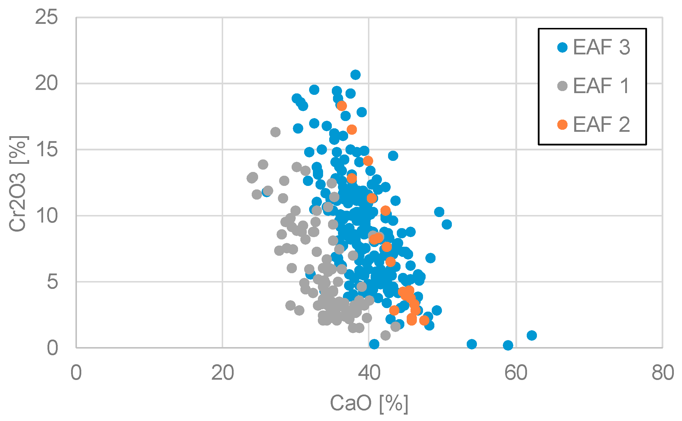
2. EAF Slag Characteristics at High Cr Steel Melts

EAF slags for melting of Cr stainless steel grades are based on addition of lime (and sometimes dololime or clinker) and characterized by varying Cr2O3 concentrations up to 20 wt.%. As Cr2O3 saturation in the slag is already achieved at few wt.%, these slags are often heavily over-saturated with Cr2O3 and/or MgO-bearing solids and therefore difficult to foam. Increasing the typical slag basicity from 1.2–1.5 to 1.5–1.6 increases the foaming index for stainless slags [14]. Typical mean slag compositions at tapping stage from three modern stainless steel EAFs are given in Table 1 and Figure 1. As the EAF tapping process contributes to Cr2O3 recovery from the slag and adjusts slightly the slag basicity, the slag samples have been taken from the transport ladle shortly after tapping. Slag analysis have been provided by plant laboratory with standardized equipment.
FeO content is low due to low Fe activity in ferrochromium melts. Average Cr2O3 content ranges from 6 to 9%, CaO from 34 to 43% (Table 1). Cr2O3 concentration for all three cases is inversely proportional to CaO concentration (Figure 1) which can be explained by the increase in Cr2O3 activity coefficient with increasing basicity, i.e., either CaO/SiO2 [15] or (CaO + MgO)/(SiO2 + Al2O3) [16]. No significant correlation was found between CaO and MgO or SiO2. Based on CrOx activity measurements in the system CaO-SiO2-CrOx, slag basicity at 1.37 was recommended for the optimum decarburization at high CrOx activity [15] with matches with average basicity of EAF 2 and 3 (Table 1). Al2O3 does not significantly affect Cr2O3 activity coefficient at typical slag compositions [16].
The average basicity CaO/SiO2 after FeSi addition at tapping is in the range 1.0 to 1.4, in order to minimize Cr2O3 formation by high Cr2O3 activity in the slag. Lower basicity at tapping, e.g., by FeSi addition, improve mixing with steel melt at tapping. Concerning the Cr leaching of the solidified slag on the other hand, basicity at 1.5 that has been examined as the optimum basicity for Cr2O3 bound in spinel with minimum Cr leaching [7]. Basicity < 1.5, however, facilitates the growth of spinels [5] and increases the enrichment ratio of Cr2O3 in the spinels [17].
The decreasing Cr2O3 with CaO concentration indicates the reduction of Cr2O3 with lime addition, i.e., increased Cr2O3 activity at high basicity as shown in thermodynamic simulations of the stainless steel production process for a 110 t EAF [18]. These simulations have been performed with FactSage [13]. FactSage contains the database validated for the CaO-MgO-Al2O3-CrO-Cr2O3 system [19,20] with experimental results on phase relations of periclase, (Cr,Al)2O3, Mg(Cr,Al)2O4 spinel, C2S and oxide liquid in both oxidizing and reducing conditions.

3. Modelling

3.1. FactSage and Database

FactSage thermodynamic software 7.3 version contains many thermodynamic databases for pyrometallurgical applications. For the stainless steelmaking, FACTPS pure substance compound database, FTOxid database and FSStel database (or FTmisc-FeLq database) can be used. In particular, the FTOxid database contains many large solution phases. For example, oxide solution phases important for the present stainless steelmaking process calculations are available in the database:
(i)
Liquid Slag: CaO-MgO-SiO2-Al2O3-FeO-Fe2O3-MnO-Mn2O3-CrO-Cr2O3-S-P-F-etc.
(ii)
Spinel phase: (Mg,Fe,Mn,..)[Cr,Al,Fe,..]2O4
(iii)
Monoxide phase: MgO-CaO-FeO-MnO rocksalt phase with a small solubility of Al2O3, Cr2O3, etc.
(iv)
Dicalcium silicate phase: Ca2SiO4-rich solution phase, (Ca,Mg,Fe,Mn)2SiO4 solid solution
(v)
Corundum phase: (Cr,Al,Fe)2O3
(vi)
Olivine phase: (Mg,Mn,Fe,Ca)2SiO4 solid solution
The details of the thermodynamic database can be found elsewhere [21] and the most recent information is available on the FactSage website (www.factsage.com).

3.2. Modelling of Cr-Bearing Slags

Thermodynamic calculations based on phase equilibrium approach with FactSage [13] have been applied in previous studies in order to model the evolution of the process slag in stainless steelmaking [18]. Simulation results reproduced the observed slag microstructures [22]. The main phases during the second half of the EAF process are Mg(Cr,Al)2O4 spinel, calcium silicates (C2S, C3S) and oxide liquid depending on slag temperature. The oxygen partial pressure was increasing with melting time and finally in the range of P(O2) = 10−9 atm with good prediction of the tapped steel composition [9].
Cr-bearing slags from the AOD converter have been successfully modelled with phase equilibrium calculations showing equilibrium of MgCr2O4 spinel solid solution and C2S with the oxide liquid at tapping [6]. An updated database has been validated with new phase equilibrium data in the Cr-bearing slag system [23].
The phase equilibrium diagrams in the system CaO-SiO2-MgO-Al2O3-Cr2O3 at temperatures from 1500 °C to 1800 °C are calculated in Figure 2 using FactSage [13]. Both Al2O3 and Cr2O3 are fixed to be 5 wt.%, which are corresponding with typical compositions of EAF slags for stainless steelmaking in Table 1. Oxygen partial pressure was set to be 10-9 atm for the calculations following the preceding studies [18,20,23]. Cr can change its oxidation state between +2 and +3 in both solid and liquid state depending on the oxygen partial pressure. Therefore, the proper oxygen partial pressure for the target process is important in the phase diagram calculations. As the final period of the EAF process with low Cr2O3 content is the most interesting for the C2S stability in the tapped slag, the phase assemblages were calculated for the CaO-MgO-SiO2-5% Al2O3-5% Cr2O3 at P(O2) = 10−9 atm in this study.
It is important to realize that slag compositions with SiO2 < 25% are not relevant for stainless steel slags (Table 1). Therefore, the complex phase assemblages with SiO2 < 25% in Figure 2 are of lower importance. Saturation lines of MgO (thick red lines in Figure 2) are important in order to minimize corrosive wear of the MgO-based EAF hearth lining and sidewalls of EAF, ladle or AOD by approaching aMgO = 1. It is interesting to note that the MgO saturation line is rather robust against temperature (Figure 2) and also against variations of oxygen activity. This behaviour is very similar to the MgO saturation in the system MgO-CaO-FeO-SiO2 for carbon steel slags [12]. The MgO level of the slag depends on the addition of MgO-bearing slag former besides lime, e.g., doloma. At significantly undersaturated MgO slag composition, the dissolution of the MgO hearth lining may increase the MgO content of the slag until saturation is achieved. The saturation field of C2S is important in order to control the C2S component in the cooled stainless steel slag. According to the calculated diagram, Mg(Cr,Al)2O4 spinel solution appears in MgO-saturation region until 1700 °C. The amount of spinel solid is about 5 wt.% of the entire slag due to limited amount of Cr2O3 (5%) used in the calculation. This means when the slag is MgO saturated, about 5% of solid spinel phase can exist in slag as a solid phase.
The calculated phase assemblages with varying Cr2O3 content from 3% to 10% at 1600 °C and 1700 °C are presented in Figure 3. In the diagram, only MgO saturation and C2S saturation lines are plotted in order to see the variation of these saturation lines with Cr2O3 content. The amount of Cr2O3 influences the amount and stability of Mg(Cr,Al)2O4 spinel, but the saturation lines of MgO and C2S are rather robust against Cr2O3 variations. Variations of Al2O3 on the saturation lines are of less importance as the range of Al2O3 compositions is close to 5% in stainless steelmaking slag (4% to 6% in Table 1).

4. Results: Application to Slag Analysis Data from Stainless Steelmaking

As shown in the previous sections, the phase diagrams in Figure 2 and Figure 3 can be applied with reasonable precision to the analysis of EAF slag data at tapping that show a range of Cr2O3 between 3% and 10% at typical tapping temperatures between 1600 °C and 1700 °C. In contrast to the MgO and C2S saturation lines, the portion of Mg(Cr,Al)2O4 spinels and (Cr,Al)2O3 depends more sensitively on temperature and oxygen activity. However, details about the amount of spinels in the slag, i.e., the saturation degree, are of less importance here because these EAF process conditions (temperature distribution, oxygen fugacity) are still difficult to measure in the EAF and to control or adapt at a given EAF design.
As mentioned above, MgO saturation line in the slag system is important for the corrosion of MgO-based refractory in stainless steelmaking process. In order to monitor the saturation of MgO periclase and C2S at tapping temperature, i.e., 1600 °C to 1700 °C, the phase diagram in Figure 3 can be used. Slag compositions from three stainless steelmaking EAFs are plotted in Figure 4, Figure 5 and Figure 6. It should be noted that these 3 EAFs have different process strategies.

5. Discussion

The EAF slags of this study are over-saturated with spinel phase (that is, spinel solids are floating on liquid slag). Most of the slags are saturated with MgO periclase or are close to periclase saturation. This is expected due to MgO addition with dololime and dissolution from the MgO hearth and sidewall lining depending on slag temperature and process time, which is very similar to carbon steelmaking slags in the very different system CaO-MgO-SiO2-FeOx [12]. The information about the portion of MgO oversaturated or undersaturated slags at tapping can be used to adjust the input of magnesia-bearing slag formers in order to minimize corrosion of the lining and specific refractory costs, and to maximize lining lifetime.
Published slag diagrams for carbon steelmaking slags (e.g., isothermal stability diagrams [1] or phase equilibrium diagrams [12]) are not appropriate for Cr stainless steelmaking due to the different FeO content. The proposed diagram in Figure 4, Figure 5 and Figure 6 can be applied at the stainless steel plants in order to monitor the slag operation, to check strategy of slag operation and to adjust slag former addition.
The comparison of three EAF operations in Figure 4 to Figure 6 clearly shows that the slags are quite different in terms of C2S saturation. The monitor and control of the EAF slag compositions to C2S saturation is manageable because the slag composition with respect to CaO, SiO2, and MgO can be determined from raw material input and mass balance calculations. The C2S saturation is important for the refining capacity of slags, but it can cause the disintegration of solidified slag.
EAF 1 is operating at the MgO saturation but with a clearly defined distance to C2S saturation which represents a valorised use of the tapped EAF slag (Figure 4). This is achieved by a rather low CaO level and CaO/SiO2 basicity (1.04, Table 1). However, the Cr2O3 activity is kept a high level by applying an increased MgO input in order to keep sufficiently high (CaO + MgO)/(SiO2 + Al2O3) basicity (1.26, Table 1). Increased MgO input also helps to minimize corrosion of the magnesia refractory lining.
EAF 2 operates at lower spinel saturated levels and with a clearly increased amount of oxide liquid, i.e., with better foaming slags, but very close to C2S saturation (Figure 5). Remarkably, the slags of EAF 2 are not MgO saturated. This corresponds to a doloma hearth lining (as alternative to a magnesia lining), which shows minimum corrosion with CaO-rich slags. The C2S saturated slag can be disintegrated during the solidification, and it would be most probably dumped [11]. Therefore, this disadvantage of the C2S saturated slag is balanced by a cost-effective doloma hearth lining in combination with an EAF process slag with improved foaming index.
EAF 3 is operating with a significantly larger variation in slag compositions ranging from C2S saturated slags to MgO-oversaturated slags far from C2S saturation (Figure 6). The large variation in slag composition indicates lower process control on raw materials and EAF process conditions. Also the large portion of MgO undersaturated slags at tapping is subject to improvement. Measures to increase the process control of EAF no. 3 with focus on the slag composition can also be efficiently monitored by the given slag diagram in Figure 4, Figure 5 and Figure 6.
The distribution of the analysed slag compositions at tapping with respect to the MgO and C2S saturation diagrams is more informative than the average value of the samples, because even some portions of heats with inappropriate slag control may increase wear rate of the lining or affect the capability of EAF slags for deposit in accordance with environmental regulations.

6. Conclusions

Control of the slag composition at EAF tapping of Cr-bearing stainless steel grades is crucial in order to minimize corrosion of the EAF hearth lining and keep the slag viscosity in a feasible range for slag foaming. In addition, it is important to maximize the valorisation of stainless steel slag by the stabilization of CrOx in spinels, and to minimize the amount of C2S for deposit characteristics in agreement with high environmental standards.
We present a simplified diagram to monitor slag compositions in EAF stainless steelmaking with focus on saturation figures with MgO and C2S. The diagram was calculated for typical slag compositions in the system CaO-MgO-SiO2-Al2O3-Cr2O3 at tapping conditions using FactSage software and database.
Depending on given EAF process strategy, the control of slags near or at the C2S saturation or with a distinct distance to C2S formation can be monitored and improved. In case of magnesia based EAF hearth linings the MgO saturation figures of the slags can be efficiently monitored and optimized for minimum refractory wear and maximum lining lifetime with the same diagram.

Author Contributions

Conceptualization, methodology, original draft preparation, M.K.; validation, improved calculations, review, text improvements, I.-H.J.; providing collaboration network, resources G.H. All authors have read and agreed to the published version of the manuscript.

Funding

This research received no external funding. The APC was funded by the German Research Foundation (DFG) and the University of Bayreuth in the funding programme Open Access Publishing.

Acknowledgments

Managers of three steel plants for stainless steel production are kindly acknowledged for providing slag analysis data and permission to publish basic results in an anonymous way.

Conflicts of Interest

The authors declare no conflict of interest.

References

  1. Pretorius, E.B.; Nunnington, R.C. Stainless steel slag fundamentals—From furnace to tundish. Ironmak. Steelmak. 2002, 29, 133–139. [Google Scholar] [CrossRef]
  2. Guo, M.; Durinck, D.; Jones, P.T.; Heylen, G.; Hendrickx, R.; Baeten, R.; Blanpain, B.; Wollants, P. EAF Stainless Steel Refining-Part I: Observational Study on Chromium Recovery in an Eccentric Bottom Tapping Furnace and a Spout Tapping Furnace. Steel Res. Int. 2007, 78, 117–124. [Google Scholar] [CrossRef]
  3. Bažan, J.; Socha, L.; Kurka, V.; Jonšta, P.; Sušovský, M. Increase of chromium yield by slag reduction during production of chromium steels. IOP Conf. Ser. Mater. Sci. Eng. 2017, 179, 1–7. [Google Scholar] [CrossRef]
  4. Mees, H.; Senk, D. Reduzierung von Chromanteilen in E-Ofen-Schlacken durch Steigerung der Legierungsmitteleffizienz bei der Erzeugung von hochchromhaltigen Schmelzen (Decrease of Chromium content in EAF slags by increased efficiency of alloys at the production of high Chromium melts). In Mineralische Nebenprodukte und Abfälle 4-Aschen, Schlacken, Stäube und Baurestmassen; Thomé-Kozmiensky, K.J., Thiel, S., Thomé-Kozmiensky, E., Friedrich, B., Pretz, T., Quicker, P., Senk, D.G., Wotruba, H., Eds.; TK Verlag: Neuruppin, Germany, 2017; ISBN 978-3-944310-35-0. [Google Scholar]
  5. Kühn, M.; Mudersbach, D.; Baena Liberato, J.M.; De Angelis, V.; Capodilupo, D.; De Fries, U. Chrome Immobilization in EAF Slags from High-Alloy Steelmaking: Development of a Slag Treatment Process; EU report no. 22077-EN; Directorate-General for Research and Innovation: Brussels, Belgium, 2006; ISBN 92-79-02077-3. [Google Scholar]
  6. Kühn, M.; Mudersbach, D. Treatment of liquid EAF-slag from stainless steelmaking to produce environmental friendly construction materials. In Proceedings of the 2nd International Conference on Process Development in Iron and Steelmaking (Scanmet II), Lulea, Sweden, 6–9 June 2004; Volume 2, pp. 369–377. [Google Scholar]
  7. Zhao, Q.; Liu, C.; Cao, L.; Zheng, X.; Jian, M. Effect of Lime on Stability of Chromium in Stainless Steel Slag. Minerals 2018, 8, 424–434. [Google Scholar] [CrossRef] [Green Version]
  8. Albertsson, G.; Teng, L.; Björkman, B.; Seetharaman, S.; Engström, F. Effect of Low Oxygen Partial Pressure on the Chromium Partition in CaO–MgO–SiO2–Cr2O3–Al2O3 Synthetic Slag at Elevated Temperatures. Steel Res. Int. 2013, 84, 670–679. [Google Scholar] [CrossRef]
  9. Zeng, Q.; Li, J.; Mou, Q.; Zhu, H.; Xue, Z. Effect of FeO on Spinel Crystallization and Chromium Stability in Stainless Steel-Making Slag. J. Miner. Met. Mater. Soc. 2019, 71, 2331–2337. [Google Scholar] [CrossRef]
  10. Sano, N. Reduction of Chromium Oxide in stainless steel slags. In Proceedings of the 10th International Ferroalloys Congress, Cape Town, Africa, 1–4 February 2004; pp. 670–677, ISBN 0-9584663-5-1. [Google Scholar]
  11. Pontikes, Y.; Jones, P.T.; Geysen, D.; Blanpain, B. Options to prevent dicalcium silicate-driven disintegration of stainless steel slags. Arch. Metall. Mater. 2010, 55, 1167–1172. [Google Scholar] [CrossRef] [Green Version]
  12. Kirschen, M.; Hanna, A.; Zettl, K.-M. Improvement of EAF process and refractory consumption by advanced slag modelling. Iron Steel Technol. 2016, 13, 52–59. [Google Scholar]
  13. Bale, C.W.; Bélisle, E.; Chartrand, P.; Decterov, S.A.; Eriksson, G.; Gheribi, A.E.; Hack, K.; Jung, I.-H.; Kang, Y.-B.; Melançon, J.; et al. FactSage thermochemical software and databases–2010–2016. Calphad 2016, 54, 35–53. [Google Scholar] [CrossRef] [Green Version]
  14. Mostafee, S. A Study of EAF High-Chromium Stainless Steelmaking Slags Characteristics and Foamability. Ph.D. Thesis, Royal Institute of Technology, Stockholm, Sweden, 2011; p. 66. [Google Scholar]
  15. Morita, K.; Tsukiashi, K.; Kimura, M.; Sano, N. Activity of Chromium Oxide in CaO-SiO2 based slags at 1873 K. Steel Res. Int. 2005, 76, 279–283. [Google Scholar] [CrossRef]
  16. Dong, P.; Wang, X.; Seetharaman, S. Thermodynamic activity of Chromium Oxide in CaO-SiO2-MgO-Al2O3-CrOx melts. Steel Res. Int. 2009, 80, 202–208. [Google Scholar]
  17. Li, J.; Zeng, Q.; Mou, Q.; Yu, Y. Effect of Basicity on Precipitation of Spinel Crystals in a CaO-SiO2-MgO-Cr2O3-FeO System. High Temp. Mater. Proc. 2019, 38, 867–872. [Google Scholar] [CrossRef]
  18. Arnout, S.; Verhaeghe, F.; Blanpain, B.; Wollants, P. A thermodynamic model of the EAF process for stainless steel. In Proceedings of the European Metallurgical Conference, Dresden, Germany, 18–21 September 2005; Volume 3, pp. 1325–1337. [Google Scholar]
  19. Jung, I.-H.; Decterov, S.; Pelton, A.D. Thermodynamic modelling of MgO-Al2O3-CrO-Cr2O3 systems. J. Am. Ceram. Soc. 2005, 88, 1921–1928. [Google Scholar] [CrossRef]
  20. Arnout, S.; Guo, M.; Durinck, D.; Jones, P.T.; Blanpain, B.; Wollants, P. Phase relations in stainless steel slags. In Proceedings of the European Metallurgical Conference, Düsseldorf, Germany, 11–14 June 2007; pp. 1931–1946. [Google Scholar]
  21. Jung, I.-H. Overview of the applications of thermodynamic database to steelmaking process. Calphad 2010, 34, 332–362. [Google Scholar] [CrossRef]
  22. Durinck, D.; Jones, P.T.; Guo, M.; Verhaeghe, F.; Heylen, G.; Hendrickx, R.; Baeten, R.; Blanpain, B.; Wollants, P. EAF Stainless Steel Refining-Part II: Microstructural Slag Evolution and its Implications for Slag Foaming and Chromium Recovery. Steel Res. Int. 2007, 78, 125–135. [Google Scholar] [CrossRef]
  23. Arnout, S.; Guo, M.; Jung, I.-H.; Blanpain, B.; Wollants, P. Experimental determination of CaO-CrO-Cr2O3-MgO-SiO2 and thermodynamic modeling of the CrO-Cr2O3-MgO-SiO2 system. J. Am. Ceram. Soc. 2009, 92, 1831–1839. [Google Scholar] [CrossRef]
Figure 1. Variation of the Cr2O3 concentration in stainless steel slags with CaO content at tapping.
Metals 10 00826 g001
Figure 2. Calculated phase diagrams of the CaO-MgO-SiO2-5% Al2O3-5% Cr2O3 at P(O2) = 10−9 atm. (a) 1500, (b) 1600, (c) 1700 and (d) 1800 °C by FactSage (reproduced from [13], with permission from authors, 2016) Oliv = Mg2SiO4-rich olivine solution, Sp = Mg(Cr,Al)2O4 spinel solution, C2S = Ca2SiO4 solution, MgO = MgO-rich solution, CaO = CaO-rich solution, C3MS2 = Ca3MgSi2O8, Cor = (Cr,Al)2O3 corundum solution. Thick red lines represent the MgO-rich solid saturation line. It should be noted that the axis of Gibbs triangle diagram is re-normalized in term of CaO + MgO + SiO2 = 100 wt.%.
Metals 10 00826 g002
Figure 3. Calculated MgO and C2S saturation lines of the CaO-MgO-SiO2-5% Al2O3-Cr2O3 system with 3% to 10% Cr2O3 at P(O2) = 10−9 atm. (a) T = 1600 °C and (b) 1700 °C.
Metals 10 00826 g003
Figure 4. Slag compositions at tapping from EAF 1 versus saturation lines of MgO and C2S. Saturation lines are calculated by FactSage (reproduced from [13]) in the system CaO-MgO-SiO2-5wt.Al2O3-3~10 wt.Cr2O3 at 1600 °C and 1700 °C (see Figure 3).
Metals 10 00826 g004
Figure 5. Slag compositions at tapping from EAF 2 versus saturation lines of MgO and C2S. Saturation lines are calculated by FactSage (reproduced from [13]) in the system CaO-MgO-SiO2-5wt.Al2O3-3~10wt.Cr2O3 at 1600 °C and 1700 °C (see Figure 3).
Metals 10 00826 g005
Figure 6. Slag compositions at tapping from EAF 3 versus saturation lines of MgO and C2S. Saturation lines are calculated by FactSage (reproduced from [13]) in the system CaO-MgO-SiO2-5wt.Al2O3-3~10wt.Cr2O3 at 1600 °C and 1700 °C (see Figure 3).
Metals 10 00826 g006
Table 1. Average slag compositions at the tapping stage of three EAFs for stainless steel production (in wt.%).
EAFMgOCaOFeOAl2O3SiO2MnOCr2O3TiO2TotalBasicity
114.933.81.476.0132.53.555.941.73100.01.04 11.26 2
27.443.0n.a.4.3431.4n.a.7.191.3094.71.37 11.41 2
310.239.31.474.6530.42.789.051.3399.21.31 11.41 2
4 [5] 33.0844.42.295.6428.32.6910.13n.a.96.51.57 11.40 2
5 [14]7.047.41.24.631.72.34.70.899.71.51 11.50 2
1 basicity CaO/SiO2, 2 basicity (CaO + MgO)/(SiO2 + Al2O3), 3 at EAF before tapping, n.a.: not available.

