Article

On the Influence of the Tool Path and Intrusion Depth on the Geometrical Accuracy in Incremental Sheet Forming

by
Roman Ulrich Christopher Schmitz
*,
Thomas Bremen
,
David Benjamin Bailly
and
Gerhard Kurt Peter Hirt
Institute of Metal Forming, RWTH Aachen University, Intzestr. 10, 52072 Aachen, Germany
*
Author to whom correspondence should be addressed.
Metals 2020, 10(5), 661; https://doi.org/10.3390/met10050661
Submission received: 7 April 2020 / Revised: 30 April 2020 / Accepted: 15 May 2020 / Published: 19 May 2020

Abstract

:
Incremental sheet forming (ISF) is a flexible sheet metal forming process to realize products within short time from design to the first produced part. Although fundamental research on ISF has been carried out around the world, ISF still misses commonly required tolerances for industrial application. In this study, the influences of tool path as well as intrusion depth of the forming tool into the sheet material on the geometrical accuracy were investigated. In the conducted experiments, both flat and stretch-formed sheet metal blanks with different tool paths and intrusion depths were examined. Experimental and numerical investigations showed that changes in the range of a tenth millimeter of the intrusion depth with a consistent tool path lead to different resulting part geometries. A better understanding of the sensitive influence of the tool path and the intrusion depth on the resulting geometry might lead to more accurate parts in the future.

1. Introduction

Incremental Sheet Forming (ISF) has reached by now a high level of awareness in the industry as a forming technique for rapid prototyping or small batch production of sheet metal parts. Over the last decades, scientists and engineers from all over the world have investigated this process with the aim to achieve a flexible production of prototypes or small batches in the automotive industry, aerospace industry, and others. Thus, many relationships and influencing factors that affect the final geometrical accuracy of a part are already identified. However, for many components and applications, the required geometrical tolerances cannot be achieved. Deviations of the final geometry compared to the target geometry are too large and still hinder an industrial application of this technology. The resulting geometrical accuracy depends on many influencing factors that are interdepending and, in many cases, cannot be controlled independently. This makes the process layout a complex and iterative process. Knowledge about these influencing factors is limited to the fact that it is known which influencing factor increases or decreases an effect, but not to what extent. One example for this is the tool diameter: the formability in ISF increases with decreasing tool diameter [1]. This statement cannot be formulated more specifically without knowledge about material, sheet thickness, wall angle, and several other influencing factors. There is still not enough process understanding to deal with all the possible interdependencies. While geometry correction algorithms sometimes achieve good results for some parts, they also might raise new questions, problems, and geometrical deviations for other parts [2,3]. With the experience from many manufactured parts for various industries, the authors found different forming results for the same parts depending on the dominating tool path direction. This makes it even more difficult to achieve the target geometry for new geometries. Therefore, this needs to be investigated further. After focusing on the sensitivity of the tool path direction, questions regarding other path parameters arose, in particular on the intrusion depth and how it influences the forming result.
This work is therefore structured as follows: First, a brief overview is given on the state of the art in incremental sheet forming with particular attention to the tool path. Then, finite element (FE) models and experiments are used to investigate and demonstrate the sensitivity of the tool path direction and the intrusion depth.
Incremental sheet forming is a flexible forming process for the production of small batches and prototypes. The process is characterized by incremental plastic deformations of the sheet metal, by a computerized numerical controlled (CNC) tool, which continuously moves along the contour of the target geometry according to a predefined tool path. A general distinction is made between single-point incremental forming (SPIF) and two-point incremental forming (TPIF), whereby in both cases the basic concept of local plastic deformation is retained. TPIF uses a partial or full die as a support tool, which increases the geometrical accuracy [1]. SPIF does not use a support tool, which provides greater flexibility at the expense of geometrical accuracy. Among others, Hirt et al. [4] and Bambach et al. [5] were able to demonstrate a high reproducibility of incremental sheet forming parts and conclude that the geometrical accuracy can be increased by adapting or optimizing the tool path. The influence of the tool path on the resulting geometry is therefore a central issue of current research. There is already a certain amount of literature which deals with the relationships between different tool paths or path strategies and the effect on the part geometry.
Hirt et al. [6], for example, stated that the achieved geometrical accuracy can be significantly increased by multi-stage forming strategies compared to single-stage forming strategies. A multi-stage forming strategy is a path strategy in which the final contour of the part is gradually approximated within several steps until the target geometry is reached in a final step, while the forming time is significantly increased. This confirms the underlying assumption that the tool path has a high influence on the part geometry. By a specific adjustment of the tool path, in this case by the application of a multi-stage forming strategy, geometrical properties of the sheet metal can be influenced in a systematical manner. These observations were confirmed by Duflou et al. [7], among others. By using a multi-stage strategy in the production of a solar cooker, the achieved component accuracy was significantly increased. For “multi-pass forming strategies”, Malhotra et al. [8] showed that the direction in which the tool moves over the sheet (inwards or outwards in multi-stage forming) also has a significant influence on the resulting part geometry. Thus, not only the tool path strategy itself could have an influence, but also the direction in which the sheet metal is formed. In addition, there are various approaches to generate specialized tool paths that try to take into account the above-mentioned relationships. For example, Wang et. al. [9] could increase the formability and geometrical accuracy at the expense of surface quality by circular movements of the tool on the surface during the path. A modification of the standard paths created by most computer aided design (CAD)/computer aided manufacturing (CAM) applications, which is based on the knowledge of different influencing parameters, offers the ability to modify the geometrical accuracy.
To improve the forming results, correction algorithms are described in the literature that generate new paths or adapt existing paths. Bambach et al. [10] presented a correction mechanism, in which the final geometry is scanned and a new tool path is generated based on the deviation from the target geometry. The actual geometry is mirrored in contrast to the target geometry and a new tool path is generated based on this overbent geometry. The intensity of overbending can be adjusted by a scaling factor. This correction mechanism, which is particularly suitable for SPIF, has in some cases increased the geometrical accuracy. However, the disadvantage of the overbending strategy is the development of bulges, which is based on an enlargement of the surface by creating a longer tool path than the actual part contour [11]. Lu et al. [12] worked on using a two-dimensional model predictive control (MPC) algorithm to control and optimize the tool path during the forming process. This resulted in increases of the achieved accuracy for the presented component geometries. Allwood et al. [13] were able to show an on-line feedback control algorithm in their work. The reaction of the sheet metal to small deflections of the tool path in different directions is measured optically. Based on this reaction, the following part of the tool path can be adapted, which increases the geometrical accuracy. Lu et al. [12] and Allwood et al. [13] did not consider trimming of the parts in the presented investigations.
Another way to improve the geometrical accuracy is to combine incremental sheet forming with stretch forming. In stretch forming, a clamped sheet is formed over a lower die. The die has the shape of the target geometry. By combining these processes, the sheet can already be formed into an initial preform with stretch forming. This enables a reduced forming time compared to pure ISF because only the remaining complex areas like cavities have to be formed by incremental sheet forming. Besides the reduction of process time, Araghi et al. [14,15] were able to show that the superimposed tensile stresses lead to a more homogeneous strain distribution along the sheet thickness, which decreases springback.
In conclusion, the literature already describes investigations and proves the influence of the selected tool path strategy on the geometrical part accuracy. Based on this, a multitude of correction mechanisms for the targeted adaptation or generation of tool paths is described. Nevertheless, a fundamental understanding between the selected tool path strategy and the resulting geometrical accuracy is still not available. For this reason, one part of this paper focuses on the influence of the tool path direction in which the forming tool moves within a tool path strategy.
However, in conventional process planning for incremental sheet forming, the tool path direction as well as the intrusion depth are mostly not the main focus. The intrusion depth i is defined as the distance by which the tool penetrates the sheet material and is shown schematically in Figure 1b. This may happen in ISF as well as in the process combination for stretch forming and ISF. If sheet thinning is taken into account for process planning of the tool path (see Figure 1a) (blue, sheet thickness t1), then it is usually determined using simplified models such as the sine law. These models are subjected to certain limitations and assumptions. Therefore, they are not generally suitable for a precise prediction of sheet thickness distribution, especially in corners, radii, and edges [16]. Thus, accepting these assumptions leads to cases where the forming tool intrudes the sheet material. By intruding the sheet material, which may happen due to several process inaccuracies such as the deformation of lower dies or incorrect tool path planning, the state of stress in the sheet might be changed leading to geometrical deviations. Consequently, the following investigations aim to answer the following questions:
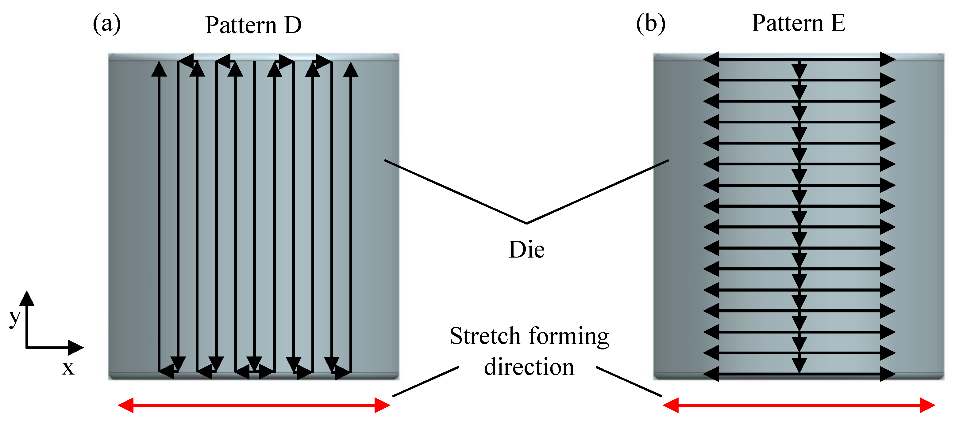
  • Does the tool path direction influence the final part geometry?
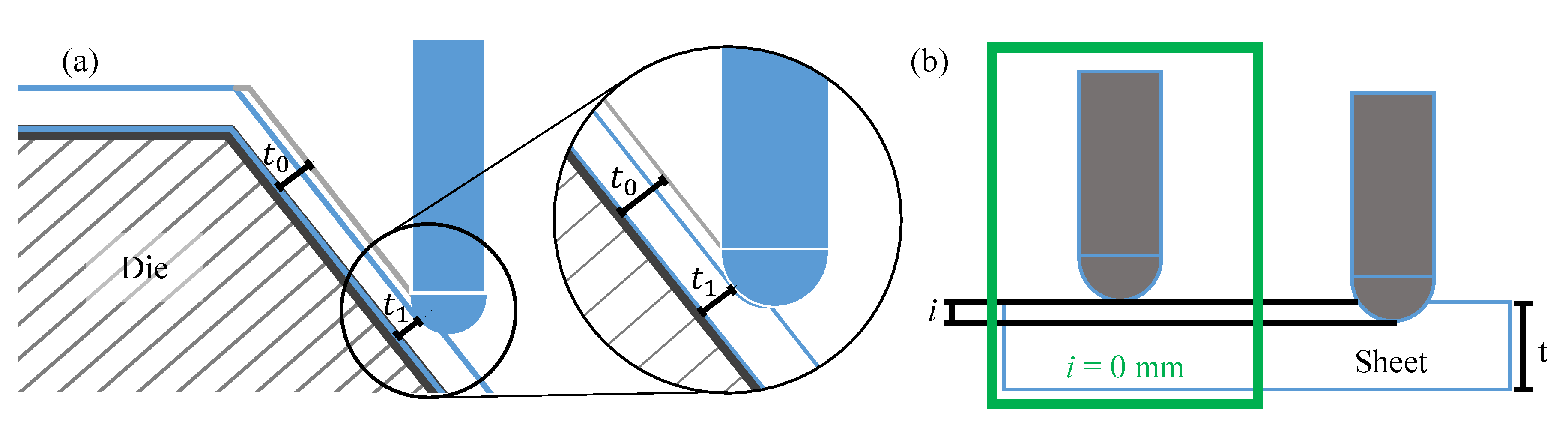
  • Is there an influence of the intrusion depth on the resulting part geometry?
Both the influence of tool path and intrusion depth have many interdependencies with other parameters and especially with the part geometry. Hence, this paper presents a simple test setup, trying to exclude the influence of the part geometry, using flat specimens in the first setup. These investigations aim to isolate the influence of tool path direction and intrusion depth as far as possible.
The presented results from experiments and FE simulations will demonstrate that the influence of the tool path direction and the intrusion depth on the resulting part geometry is very sensitive. Besides the tool path design, such as “z-level” or “multi-stage”, even the tool path direction influences the part geometry. To be able to control the geometrical accuracy in ISF at all in the future, the authors would like to raise the awareness for these effects and to motivate further investigations with this paper. The investigations are supported by an FE model, which reproduces the experimental findings qualitatively and therefore enables a deeper understanding of the influences on the geometrical accuracy in further work in the future.

2. Materials and Methods

To answer the questions on the influence of the tool path directions and the intrusion depths on the geometrical accuracy, experiments and FE simulations were carried out using mild steel 1.0338. The first experimental setup concentrated on incremental sheet forming only with a very basic concept of small and flat specimens to reduce the number of possible influences. The second setup took a previous stretch forming operation in combination with subsequent ISF into account. The geometry of the resulting parts from experiments was measured using a 3D-scanner (HandyScan 700, CREAFORM, Lévis QC, Canada), which provides an accuracy of up to 0.03 mm. For all experiments, Multidraw 472 (Zeller + Gmelin GmbH & Co. KG, Eislingen/Fils, Germany) was used as lubricant to reduce friction to a minimum.

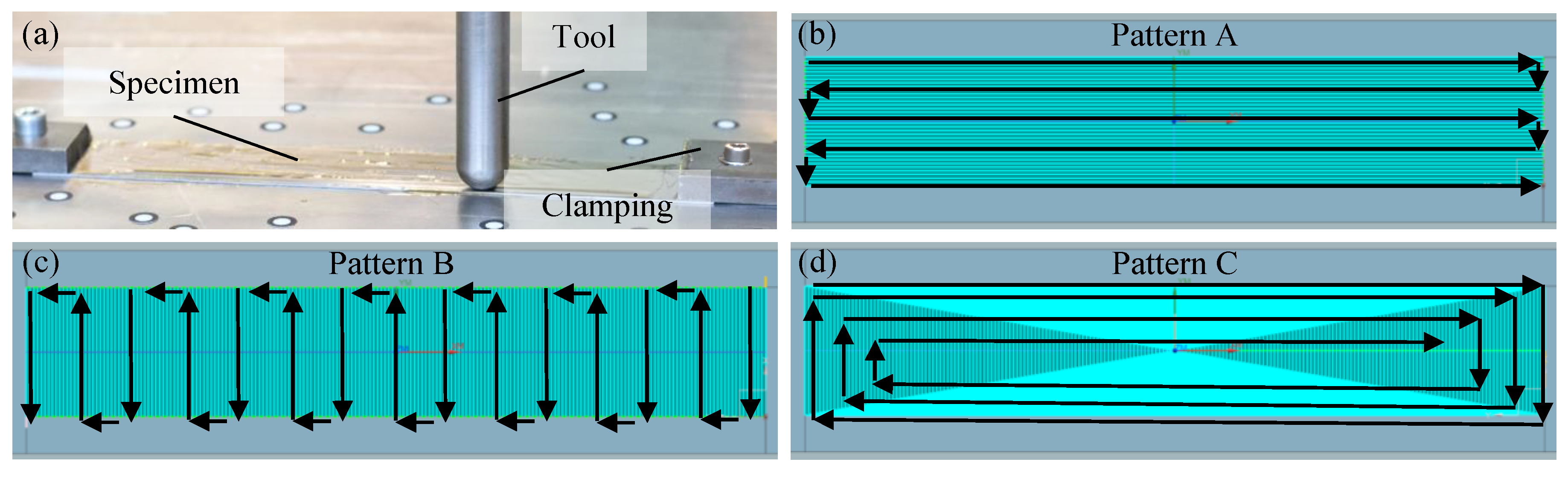
2.1. Experimental Setup for Pure ISF

The concept for the first experimental setup aims to isolate the influence of the tool path direction and the intrusion depth by forming a flat target geometry from flat specimens with different tool path patterns and observe whether the results will show different final part geometries. Flat specimens of DC04 (1.0338) with dimensions of 260 mm × 40 mm × 1 mm were clamped on the two short opposing sides, see Figure 2a.
A hemispherical tool with a diameter of 20 mm was used for forming. To investigate the influence on the final part geometry three different tool path patterns were tested in combination with two different intrusion depths. To compare different path directions, the forming patterns were chosen longitudinally, transversely, and quadrangular to the specimen geometry and are presented in Figure 2b–d as Patterns A–C. These patterns are all acting on the same flat surface area and have a pitch between the path lines of 1 mm. Pattern A has a major forming direction alternating parallel to the longest sheet side while moving forward in the direction of the shortest sheet side. Pattern B alternates parallel to the shortest sheet side while moving forward in the longest sheet side direction. Pattern C follows a square spiral and starts along the outer edges while moving further towards the center of the specimen. Due to the dimensions of the specimen, the paths along the long specimen edges are closer to each other compared to the paths on the shorter edges. The real tool paths are the plotted blue lines, which are hardly visible because of the small step size between the lines. Thus, the black lines with arrows are meant to clarify the tool path patterns to the reader in Figure 2. For the tested three patterns, predefined intrusion depths of 0.1 and 0.3 mm were chosen to verify whether there is an influence. An intrusion depth of i = 0 mm was not considered, as no contact between tool and sheet would occur.

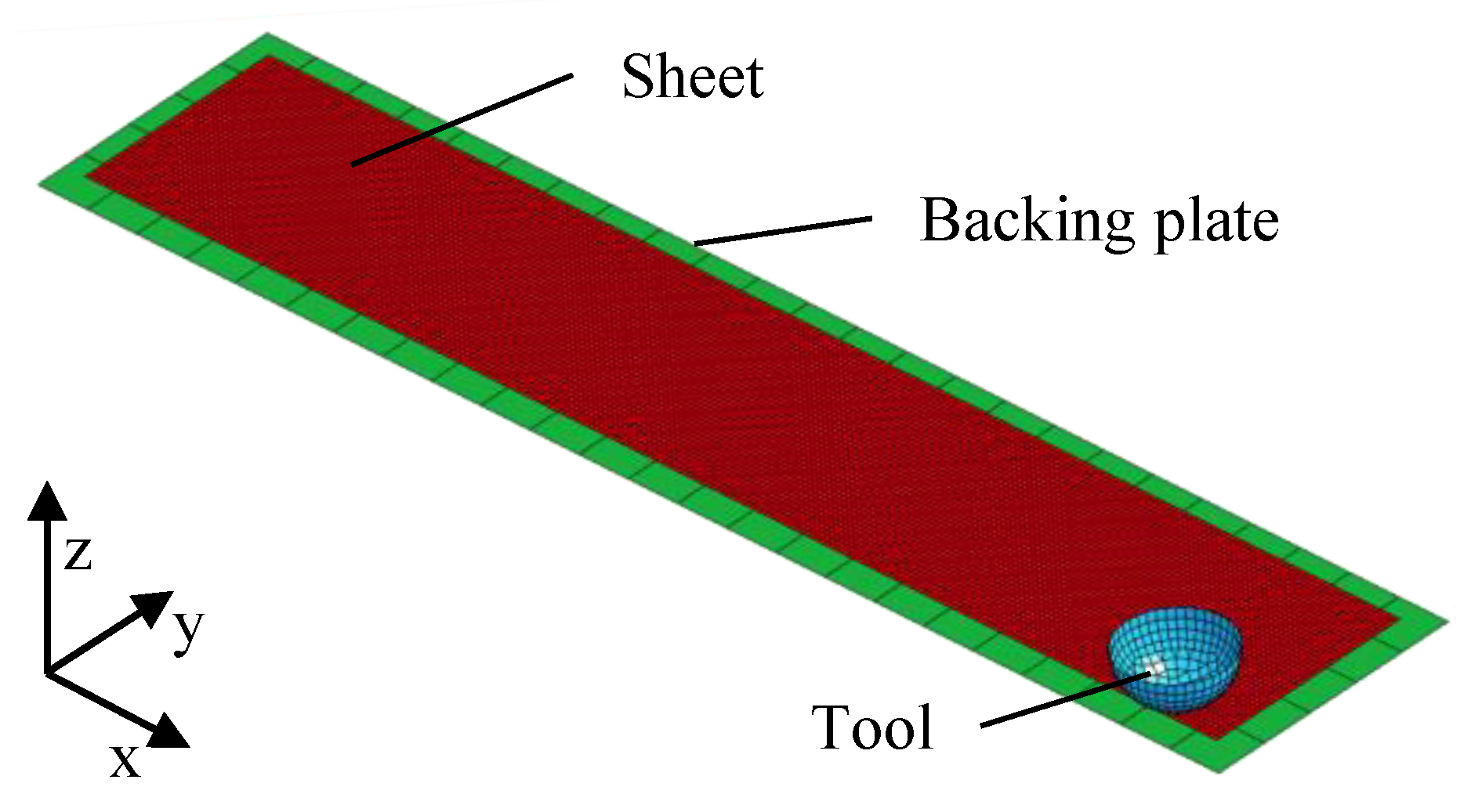
2.2. FE Model for Pure ISF

Finite element simulations of forming processes allow for analysis of the processes occurring in the sheet metal that can hardly be detected in experiments. For example, stress and strain distributions over the sheet thickness can be investigated. Thus, an FE model of the incremental forming process was built to represent the first experimental setup. The aim was to show whether this simple FE model could reproduce the geometrical differences resulting from different tool path directions. Only forming, without unclamping was modeled and was later compared to the clamped state of the experimental parts. The springback taking place at unclamping or trimming was not considered in this study, as the focus here was on achieving the clamped geometry. For the simulation, the explicit FE solver LS-DYNA R901 (Livermore Software Technology Corporation, Livermore CA, United States) was used. This model is a first step towards designing and optimizing the process regarding tool path and intrusion depth via FE simulations in the future. The elastic–plastic material model 24-piecewise linear plasticity was applied for the sheet metal, considering a flow curve for 1.0338. The tool with a diameter of 20 mm and the backing plate were assumed to be rigid and the tool path was coordinate based. The shell element formulation 2 Belytschko-Tsay was chosen for all parts while the sheet was meshed with 0.5 mm elements, the backing plate with 10 mm elements, and the tool element size was around 1.5 mm. Friction was not considered in this simple model by assuming a friction coefficient of µ = 0. Mass scaling was used and the ratio of kinetic energy to internal energy is within a moderate range. The clamping was modeled as linear fixations with no degree of freedom in all coordinate axes and rotations in a way that the short sheet edges were fully constrained. The assembled model is presented in Figure 3.

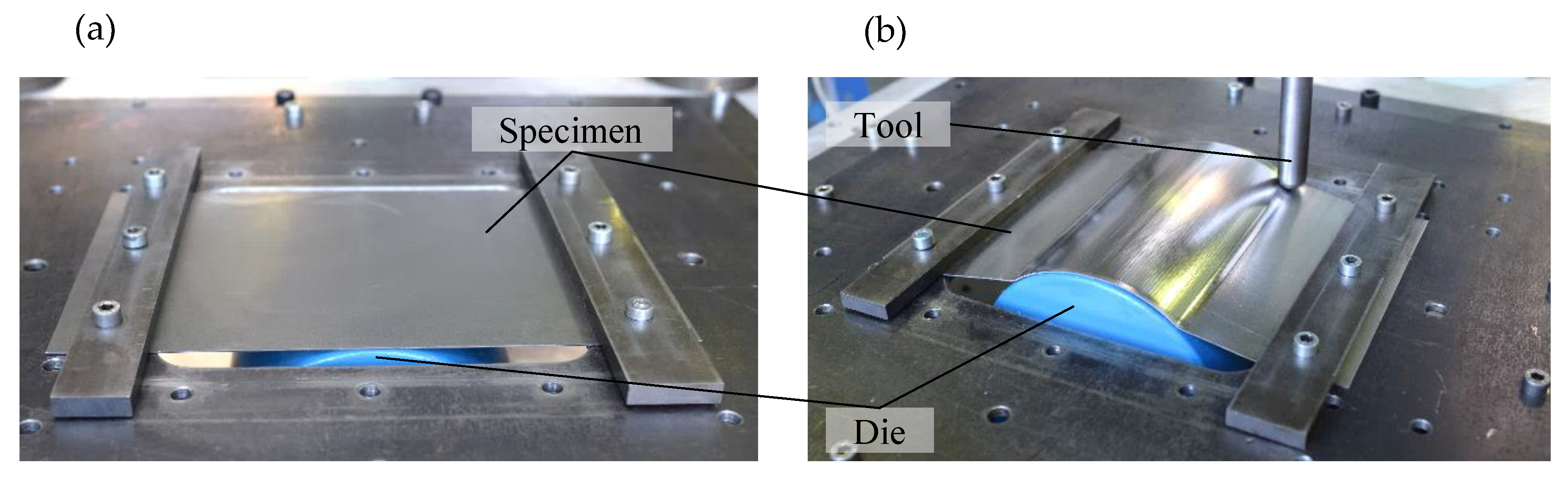
2.3. Experimental Setup for Stretch-formed Sheets

In the state of the art, the advantage of the process combination of stretch forming and incremental sheet forming on the resulting part accuracy is pointed out. Nevertheless, the subsequent ISF process still significantly influences the final accuracy. Therefore, the second experimental setup was used to investigate the ISF process after previous stretch forming. Specimens of DC04 (1.0338) with the dimensions 300 mm × 180 mm × 1 mm were formed by conventional uniaxial stretch forming over a uniaxial curved die with a radius of 80 mm. The geometrical elongation in the stretch forming direction was designed to theoretically reach 2.5% in each case over the sheet when stretching the sheet with a downward motion of 22 mm. The experimental setup before and after forming is shown in Figure 4. Sikablock M980 (Sika Deutschland GmbH-Sika Advanced Resins, Stuttgart, Germany) was used as die material. The sheet is clamped along its two shorter sides. The deformation of the die material under load is very low. However, to exclude the possible influence of die deformation, the intrusion depth was measured and adjusted after stretch forming. The conditions were kept constant for all experiments.
The influence of the tool path on the part geometry was then investigated using two different path patterns and two intrusion depths. The intrusion depths i = 0.1 mm and i = 0.3 mm were investigated and realized by adjusting the z coordinate of the tool analogously to the first setup without considering sheet thinning and assuming i = 0 mm equals t = 1.0 mm. In all experiments, a hemispherical tool with a diameter of 20 mm was used. The examined path patterns are shown in Figure 5, and the longitudinal and transversal influence of the tool path direction on the resulting geometry was compared. In Pattern D, the forming tool moved perpendicular to the stretch forming direction, first forming one half of the geometry, and then the other half at a constant pitch of 1 mm. With this tool path design, contact between sheet and tool is maintained for each half of the part without the tool retracting and engaging continuously as in conventional z-level paths. Pattern E moved parallel to the stretch forming direction, starting from the vertex of the die with a pitch of 1 mm perpendicular to the stretch forming direction. With the exception of the tool path and intrusion depth, all other process parameters were kept constant.

3. Results and Discussion

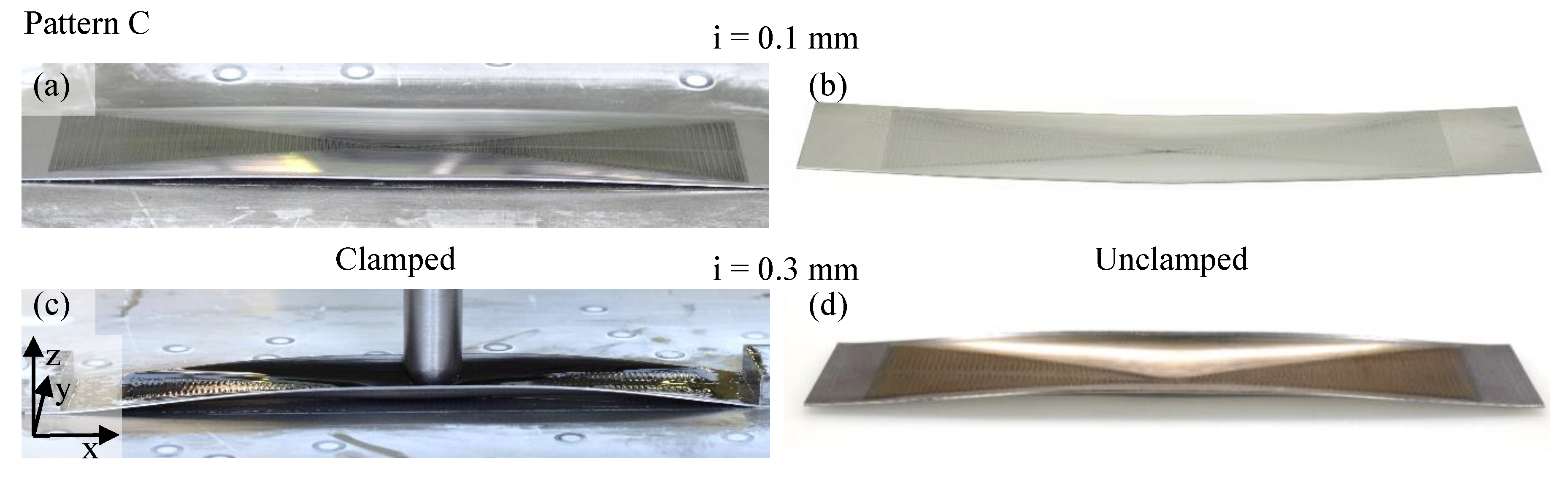
3.1. Experimental Results for Pure ISF

The experiments for the flat specimens showed a different resulting geometry for each variation of the tool path and of the intrusion depth. Each experiment was repeated three times, which showed a very reproducible observation of the investigated effects. Thus, a clear dependency of the final part geometry on the tool path direction and the intrusion depth could be identified. However, these dependencies only apply to the examined geometries. For Pattern A, the experimental results in the clamped and unclamped state are presented in Figure 6. With a slight intrusion depth of i = 0.1 mm, the forming result in the clamped state shows a concave curvature around the x-axis of the sheet specimen where the longer sides tend upwards. After unclamping, a curvature around both x- and y- axes is unveiled and the short sides tend upwards as well. Increasing the intrusion depth to i = 0.3 mm increases the curvature around the x-axis in the clamped state. After unclamping, there is still a curvature around x-axis while the short ends stay flat on the ground and the center of the specimen slightly loses contact to the ground. Therefore, a very slight convex curvature around the y-axis can be observed in contrast to the unclamped specimen with an intrusion depth of i = 0.1 mm.
Pattern B, which was formed with an alternating tool path in the short sheet direction (y-axis) and a pitch in negative x-direction, is presented in Figure 7. In a very early stage of forming, the sheet specimen shows a convex curvature around the y-axis. In front of the tool in pitch direction, this curvature keeps increasing, leading to a deeper intrusion of the tool compared to the preset intrusion depth of 0.1 mm. Towards the end of the process, however, the accumulated material pushes through under the forming tool in the x-direction, resulting in a flat end in the clamped case. Here, the hypothesis is likely that a small intrusion depth enlarges the top surface of the sheet. This results in a convex curvature already in an early stage of the forming process. Then, the intrusion increases due to the bulge in front of the forming tool, resulting in a higher plastic deformation of the sheet and a concave curvature regarding the unclamped state from right to left.
For the intrusion depth of 0.3 mm in Figure 7, a state during the forming process in the clamped state is shown to indicate more precisely what happens during the process. In this case, the accumulated material in front of the tool does not push through under the forming tool completely, resulting in a wrinkle at the end of the process. The overall deeper intrusion results in an overall concave curvature around the y-axis in the unclamped state.
Pattern C in Figure 8, which combines the dominant path directions of both previous patterns, shows similar results in the clamped and unclamped state for an intrusion depth of 0.1 mm compared to Pattern A. The long tool path segments in x-direction seem to have a stronger geometrical impact compared to the short paths in y-direction, as the resulting geometries are more similar to those in Pattern A. Nevertheless, in the clamped state, the concave curvature around the x-axis is stronger compared to Pattern A. The same applies to the unclamped state, where additionally the concave curvature around y-axis is stronger, too. For a deeper intrusion of i = 0.3 mm, the concave curvature around the x-axis increases. The curvature around y-axis can no longer be described as only concave or convex in one direction looking at Figure 9a. Even though the forming tool follows a flat 2D tool path for all compared patterns, the forming results are all different 3D curved geometries.

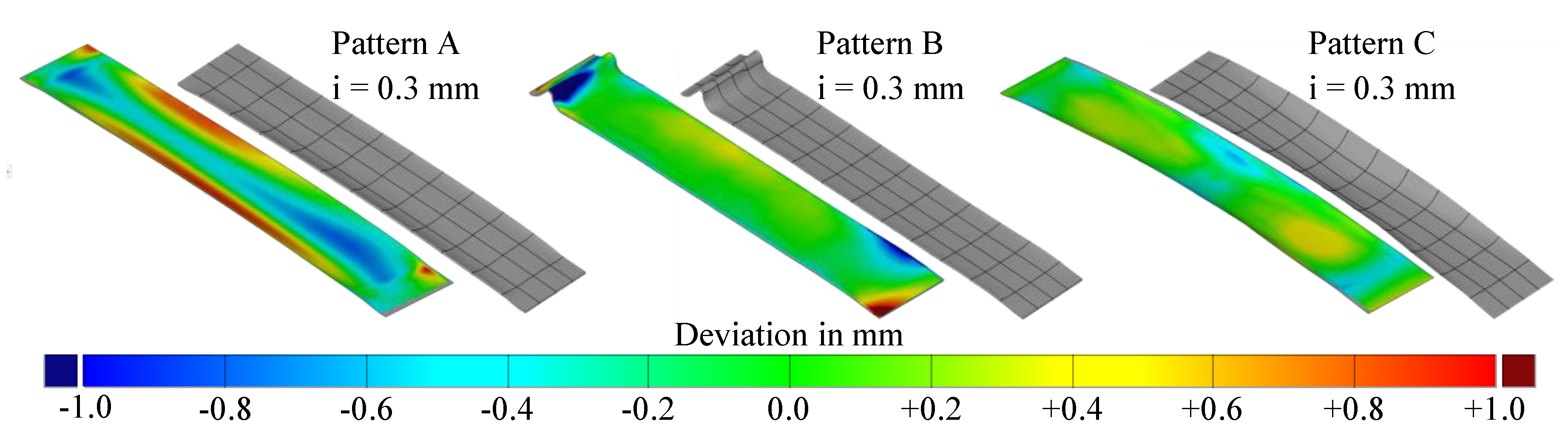
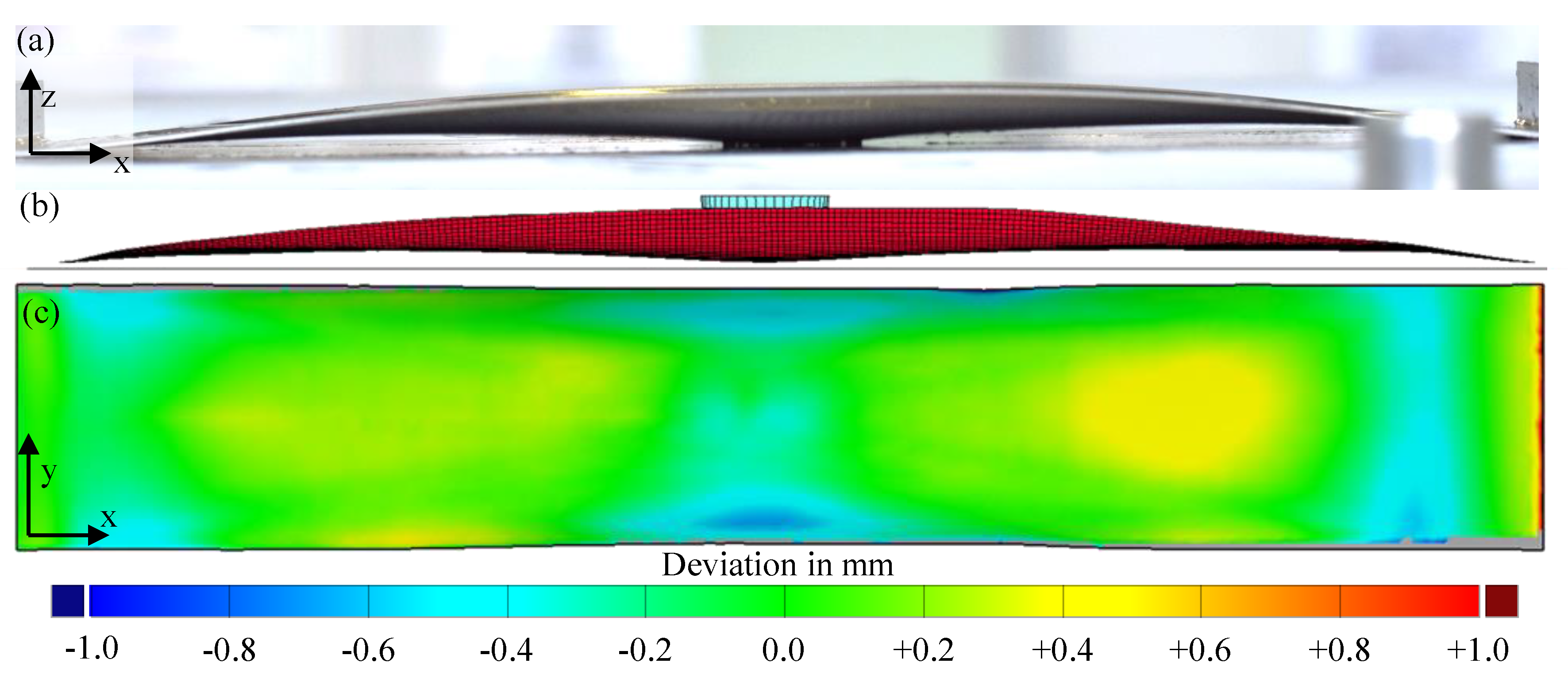
3.2. Numerical Results for Pure ISF

Figure 9a,b shows the formed ISF part of the experiment in the clamped state and FE simulation (without springback) for path Pattern C with an intrusion depth of i = 0.3 mm. A digital image correlation of the 3D-scanned surface from the experiment and the simulated geometry reveals that the simple FE model shows deviations in z-axis within a range of approximately ±0.5 mm for the example of Pattern C.
The different resulting geometries for different tool path patterns can be reproduced via the presented FE model, as can be seen in Figure 10. Here, lines parallel to the x- and y-axis have been projected onto the simulated surfaces to better visualize the forming result. The results represent the clamped state after forming. Pattern A shows the same behavior as the sheet in the experiment where the long sides tend upwards while Pattern B has the characteristic wrinkle resulting from the accumulated material. In addition, Pattern C is in good agreement with the observed effects in the experiments, as presented in Figure 9. The color plots for Patterns A and B show higher deviations, but the general resulting shape is in a good agreement in experiment and simulation.
Up to this point, it can be stated that the simple FE model is able to reproduce the geometrical influences well. Based on this finding, the model can be used in the future to analyze the distribution of stresses or the strain over the sheet thickness in different directions in more detail and thus contribute to the understanding of the mechanisms behind the different resulting geometries.

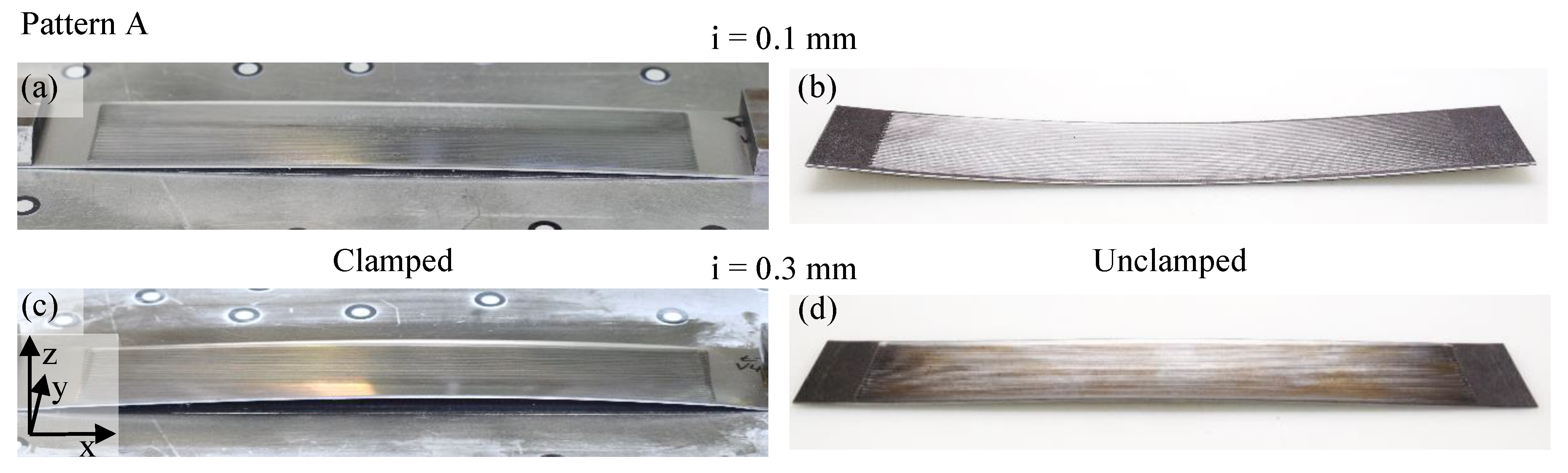
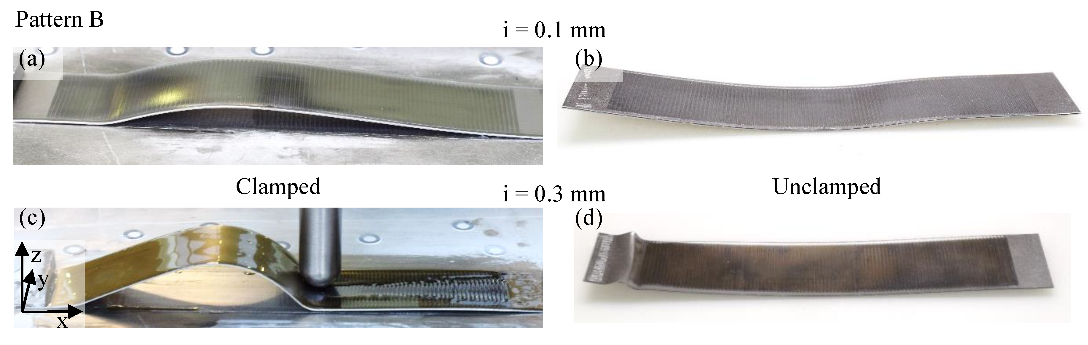
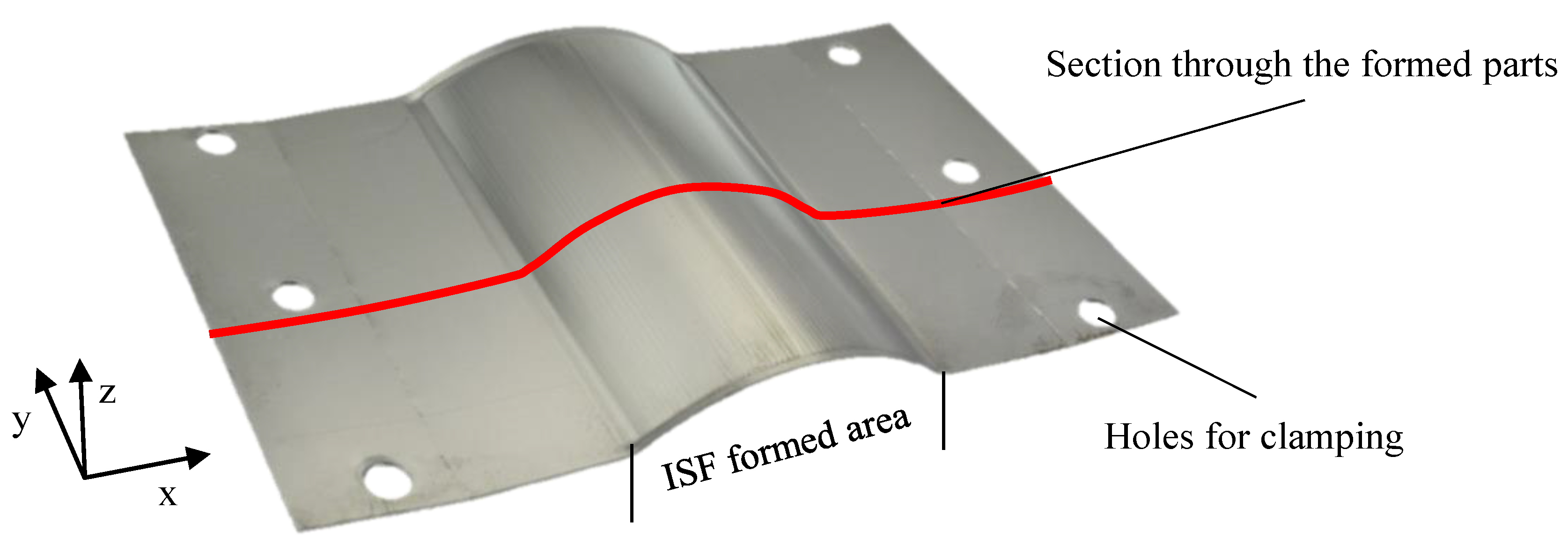
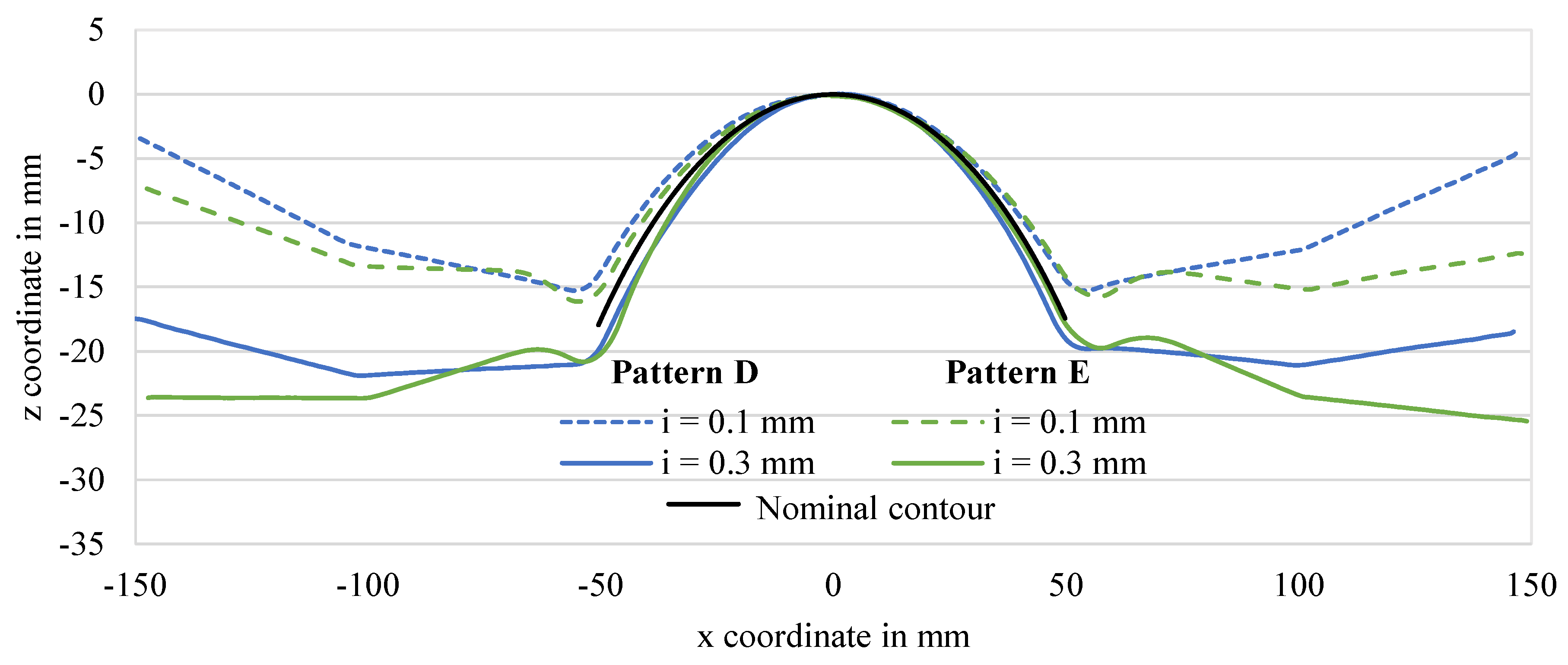
3.3. Experimental Results for Stretch-Formed Sheets

An exemplary experimental result of the second setup is presented in Figure 11. To analyze the experiments of this setup, a two-dimensional section along the stretch forming direction was carried out on the 3D scanned surfaces for all formed parts at the same position (see Figure 11). This section represents the contour of the part and is in the direction of the highest expected distortion. The extracted sections of the described experiments are shown in Figure 12.
Figure 12 shows the influence of the selected tool paths and intrusion depths on the resulting geometry based on the section from the formed and 3D scanned parts. The analyzed samples are all aligned on the vertex of their respective parabola, so that differences in the geometries can be observed. In this case, mainly the intrusion depth leads to changes in the geometry in the ISF-formed area, represented by the parabola. The direction in which the forming tool moves over the workpiece seems to play a secondary role in the ISF-formed area. However, the pattern leads to different springback behavior outside of the area formed by ISF. Here, these areas are tending more upwards for Pattern D than for Pattern E on the outer edges. In the following, a closer look at the ISF-formed area is taken. This area ranges over a length of approximately 100 mm on the x-axis from x = −50 mm to x = 50 mm.
Based on the plotted nominal contour, statements can be derived concerning the resulting geometry of the specimens. Here, the influence of the intrusion depth can be seen clearly. One possible cause for the significant differences in the geometries as a function of the intrusion depth can be the high degree of deformation. At a higher intrusion depth, a significantly larger deformation over the thickness is introduced into the material than for a smaller intrusion depth. By increasing the deformation, the sheet surface enlarges, which in turn has a direct influence on the resulting geometry, which leads to a visibly higher parabola length for both experiments with a higher intrusion depth. The different parabola lengths along the sections in Figure 12 support this hypothesis. The parabola length for Pattern D with i = 0.1 mm is 108.4 mm and 112.3 mm for i = 0.3 mm. For Pattern E and i = 0.1 mm, the parabola length is 109.1 mm and 113.1 mm for i = 0.3 mm. The parabolas with an intrusion depth of i = 0.3 mm are approximately 3.6% longer than for an intrusion depth of i = 0.1 mm.
For both patterns with an intrusion depth of 0.1 mm, springback of the specimens after unclamping can be observed, represented by the section profiles lying above the nominal contour. For an intrusion depth of 0.3 mm, even a “springforward” can be observed, as the parabola for these experiments lies on the inside of the nominal contour.
To quantify these findings, the distances on the x-axis to the nominal contour was measured at z = −15 mm on the negative side of the x-axis at approximately x = −50 mm because all sections are running along this z-coordinate. Pattern D shows a distance in x-direction to the nominal contour of x = −6.15 mm for an intrusion depth of 0.1 mm and x = +2.71 mm for an intrusion depth of 0.3 mm. For Pattern E, a similar behavior can be found by the distances in x-direction to the nominal contour of x = −3.24 mm for an intrusion depth of 0.1 mm and x = +3.81 mm for an intrusion depth of i = 0.3 mm. This exemplary quantification for z = −15 mm can be found in a similar way throughout the whole plot of the parabolas. A positive distance can be interpreted as springback and a negative distance as “springforward” for this case.
In this setup, the same areas were formed in the experiments with two different patterns and two different intrusion depths, resulting in four different section profiles of the formed part and demonstrating a highly sensitive influence of the intrusion depth on the geometrical accuracy. It should be noted here that the state of stress in the sheet is not only influenced by ISF but also by the tensile stresses from the previous stretch forming process in contrast to the first experimental setup presented in Section 3.2.

4. Conclusion

The experimental and simulative investigations on the influence of the tool path direction and the intrusion depth demonstrated their sensitivity on the resulting part geometry for single stage incremental sheet forming and the combination of stretch forming and ISF.
In the first setup for pure ISF, forming was focused on three different tool paths in combination with two different intrusion depths to investigate the influence of these parameters. To isolate the influence of these two parameters, a flat 2D target geometry was formed. The resulting part geometries are 3D shaped in different ways depending on the tool path direction and the intrusion of the tool into the sheet material.
The presented FE model is already capable of predicting the influence of different tool path strategies and intrusion depths on the resulting deformation of the flat specimen in a qualitative way.
In a second setup, the dependence of the resulting geometry on the path direction and intrusion depth was investigated for the combination of stretch forming and ISF. For both analyzed path patterns, the intrusion depth changes the resulting geometry significantly. The higher intrusion depth leads to a higher surface enlargement and to a “springforward”. The lower intrusion depth leads to springback. However, these observations cannot yet be considered as general rules and might only apply to this case and this geometry. Further investigations on these effects are planned in the future.
This study aimed to demonstrate the sensitivity of both influencing factors and to introduce an experimental setup, which allows investigating these influences in a very isolated way.
For more precise knowledge about the interdependencies and the observations made here, further investigations are necessary. To understand the observed effects more precisely, stress and strain gradients along the sheet thickness have to be considered as well as their origin and history during the process, especially regarding the path direction and intrusion depth. This can be possible with valid FE models. If the effect on the small presented parts is already significant, there is probably an even higher impact on large-scale 3D parts. Based on a deeper understanding of the forming mechanisms, it might be possible in the future to improve the geometrical accuracy using optimized tool paths and handling the intrusion depth with the awareness of its significant influence.

Author Contributions

Conceptualization, R.U.C.S., T.B., D.B.B., and G.K.P.H.; methodology, R.U.C.S. and T.B.; validation, R.U.C.S. and T.B.; formal analysis, R.U.C.S. and T.B.; investigation, R.U.C.S. and T.B.; data curation, R.U.C.S. and T.B.; writing—original draft preparation, R.U.C.S. and T.B.; writing—review and editing, R.U.C.S., T.B., D.B.B., and G.K.P.H.; visualization, R.U.C.S. and T.B.; supervision, D.B.B. and G.K.P.H.; project administration, D.B.B. and G.K.P.H.; and resources, G.K.P.H. All authors have read and agreed to the published version of the manuscript.

Funding

This research received no external funding.

Conflicts of Interest

The authors declare that they have no known competing financial interests or personal relationships that could have appeared to influence the work reported in this paper.

References

  1. Jeswiet, J.; Micari, F.; Hirt, G.; Bramley, A.; Duflou, J.; Allwood, J.M. Asymmetric single point incremental forming of sheet metal. CIRP Ann. 2005, 54, 88–114. [Google Scholar] [CrossRef]
  2. Meier, H.; Buff, B.; Laurischkat, R.; Smukala, V. Increasing the part accuracy in dieless robot-based incremental sheet metal forming. CIRP Ann. 2009, 58, 233–238. [Google Scholar] [CrossRef]
  3. Meier, H.; Laurischkat, R.; Zhu, J.; Chinesta, F.; Chastel, Y.; El Mansori, M. A model based approach to increase the part accuracy in robot based incremental sheet metal forming. AIP Conf. Proc. 2011, 1315, 1407. [Google Scholar]
  4. Hirt, G.; Junk, S.; Witulski, N. Surface Quality, Geometric Precision and Sheet Thinning in Incremental Sheet Forming. In Proceedings of the Materials Week, Munich, Germany, 1–3 October 2001; pp. 1–8. [Google Scholar]
  5. Bambach, M.; Taleb, B.A.; Hirt, G. Strategies to improve the geometric accuracy in asymmetric single point incremental forming. Prod. Eng. 2009, 3, 145–156. [Google Scholar] [CrossRef]
  6. Hirt, G.; Ames, J.; Bambach, M.; Kopp, R. Forming strategies and process modelling for CNC incremental sheet forming. CIRP Ann. 2004, 53, 203–206. [Google Scholar] [CrossRef]
  7. Duflou, J.R.; Lauwers, B.; Verbert, J.; Tunckol, Y.; Baerdemaeker, H.D. Achievable Accuracy in Single Point Incremental Forming: Case Studies. In Proceedings of the 8th European Scientific Association for material Forming Conference on Material Forming (2005), Cluj-Napoca, Romania, 27–29 April 2005; pp. 675–678. [Google Scholar]
  8. Malhotra, R.; Bhattacharya, A.; Kumar, A.; Reddy, N.V.; Cao, J. A new methodology for multi-pass single point incremental forming with mixed toolpaths. CIRP Ann. 2011, 60, 323–326. [Google Scholar] [CrossRef]
  9. Wang, J.; Li, L.; Zhou, P.; Wang, X.; Sun, S. Improving formability of sheet metals in incremental forming by equal diameter spiral tool path. Int. J. Adv. Manuf. Technol. 2018, 101, 225–234. [Google Scholar] [CrossRef]
  10. Bambach, M.; Hirt, G.; Ames, J. Modeling of optimization strategies in the incremental CNC sheet metal forming process. AIP Conf. Proc. 2004, 712, 1969–1974. [Google Scholar]
  11. Bambach, M. Process Strategies and Modelling Approaches for Asymmetric Incremental Sheet Forming. Ph.D. Thesis, RWTH Aachen University, Aachen, Germany, 12 December 2007. [Google Scholar]
  12. Lu, H.; Kearney, M.; Liu, S.; Daniel, W.J.; Meehan, P. Two-directional toolpath correction in single-point incremental forming using model predictive control. Int. J. Adv. Manuf. Technol. 2016, 91, 91–106. [Google Scholar] [CrossRef]
  13. Allwood, J.M.; Music, O.; Raithathna, A.; Duncan, S.R. Closed-loop feedback control of product properties in flexible metal forming processes with mobile tools. CIRP Ann. 2009, 58, 287–290. [Google Scholar] [CrossRef]
  14. Araghi, B.T.; Göttmann, A.; Bergweiler, G.; Saeed-Akbari, A.; Bültmann, J.; Zettler, J.; Bambach, M.; Hirt, G. Investigation on incremental sheet forming combined with laser heating and stretch forming for the production of lightweight structures. Key Eng. Mater. 2011, 473, 919–928. [Google Scholar] [CrossRef]
  15. Taleb, B.A.; Göttmann, A.; Bambach, M.; Hirt, G.; Bergweiler, G.; Diettrich, J.; Steiners, M.; Saeed-Akbari, A. Review on the development of a hybrid incremental sheet forming system for small batch sizes and individualized production. Prod. Eng. 2011, 5, 393–404. [Google Scholar] [CrossRef]
  16. Bambach, M. A geometrical model of the kinematics of incremental sheet forming for the prediction of membrane strains and sheet thickness. J. Mater. Process. Technol. 2010, 210, 1562–1573. [Google Scholar] [CrossRef]
Figure 1. (a) TPIF assuming no thinning in tool path planning (grey) and considering thinning in tool path planning (blue); and (b) scheme for tool path without intrusion (left) and with intrusion (right) (i, intrusion depth; t, sheet thickness).
Metals 10 00661 g001
Figure 2. Experimental setup (a) and tested tool path Patterns A–C (bd); blue lines, real tool path; black lines with arrows, simplified representation of the tool path.
Metals 10 00661 g002
Figure 3. Setup for FE modeling of different tool path strategies and intrusion depths.
Metals 10 00661 g003
Figure 4. Experimental setup before forming (a) and after stretch forming and ISF (b).
Metals 10 00661 g004
Figure 5. Schematic representation of the die (top view) with the tested path Patterns D (a) and E (b).
Metals 10 00661 g005
Figure 6. Pattern A: experimental results before (left, (a,c)) and after (right, (b,d)) unclamping for different intrusion depths i = 0.1 mm (top, (a,b)) and i = 0.3 mm (bottom, (c,d)).
Metals 10 00661 g006
Figure 7. Pattern B: experimental results before (left, (a,c)) and after (right, (b,d)) unclamping for different intrusion depths i = 0.1 mm (top, (a,b)) and i = 0.3 mm (bottom, (c,d)).
Metals 10 00661 g007
Figure 8. Pattern C: experimental results before (left, (a,c)) and after (right, (b,d)) unclamping for different intrusion depths i = 0.1 (top, (a,b)) and i = 0.3 (bottom, (c,d)).
Metals 10 00661 g008
Figure 9. Side view of Pattern C for experimental (a) and simulation (b) results, both in the clamped state; and geometry comparison between experiment and simulation in top view (c).
Metals 10 00661 g009
Figure 10. Comparison of FE modeled results and experiments for different tool path patterns (color plots). The grey plots with the projected lines should provide a better visibility of the curvatures.
Metals 10 00661 g010
Figure 11. Specimen formed by stretch forming and ISF with an intrusion depth of 0.3 mm with analyzed section (red line).
Metals 10 00661 g011
Figure 12. Results along the considered part sections for different path patterns and intrusion depths.
Metals 10 00661 g012

