Article

Electrochemical Investigation of the Effect of Process Parameters on the Corrosion Behavior of Aluminum-Cladded Pressure Vessel Steel Using a Friction Stir Diffusion Cladding Process

1
Mechanical Engineering Department, King Fahd University of Petroleum and Minerals (KFUPM), 31261 Dhahran, Saudi Arabia
2
Center of Research Excellence in Corrosion, King Fahd University of Petroleum & Minerals (KFUPM), 31261 Dhahran, Saudi Arabia
*
Author to whom correspondence should be addressed.
Metals 2020, 10(5), 623; https://doi.org/10.3390/met10050623
Submission received: 10 April 2020 / Revised: 7 May 2020 / Accepted: 9 May 2020 / Published: 11 May 2020
(This article belongs to the Special Issue The Electrochemical and Corrosion Behaviour of Structural Materials)

Abstract

:
Surface cladding and coatings are commonly used to protect structures against corrosion in corrosive environments. In this paper, electrochemical properties of friction stir diffusion cladded ASTM A516-70 with corrosion-resistant aluminum alloy grade 5052 are studied. The effect of process parameters, tool rotational and traverse speeds on the corrosion behavior of produced cladded steels was comparatively assessed. Electrochemical analyses revealed that the cladded steel sample provided good corrosion protection performance in comparison with the un-cladded steel substrate following an immersion test of up to 21 days in 3.5% NaCl medium. Increasing the tool traverse speed was found to negatively affect the corrosion resistance. Optimum parameters for the selected cladding system were found to be a 500 rpm tool rotational speed, and a 50 mm/min tool traverse speed for protection against general corrosion. Meanwhile, higher traverse speed demonstrated stable passivation behavior and, therefore, lower propensity for pitting localized corrosion. Post characterization of the exposed area indicated that tool shoulder marks were favorable spots for the accumulation of corrosion products.

1. Introduction

Corrosion is one of the major causes of failure in many engineering components. Several methods, such as thermal spray coatings, plasma spraying, weld overlay, vapor deposition, mechanical plating, and cladding techniques, have been used to protect structural steel materials against corrosion [1]. Cladding is among the most economical ways of protecting structures against corrosion and wear-related problems. Fusion overlay cladding (FOC) methods are used frequently for cladding on pipes, valves, flanges, bends, risers, and fittings. However, the use of conventional fusion-based techniques for cladding is considered very challenging for dissimilar clad-substrate materials. The challenges are due to the difference in both physical and mechanical properties involving the thermal coefficient of expansion, solidification, and melting temperature differences between the two cladded materials. Additionally, fusion cladding processes develop high residual stresses, and therefore post heat treatment is often required for stress relaxation. Also, defects that are generated during fusion cladding are synonymous to typical defects of the fusion welding process, where porosity, micro-cracks, and residual stresses may compromise quality and therefore, cause a sudden failure or shortening of the equipment lifespan. Thus, with friction stir diffusion cladding (FSDC)-which was developed based on a friction stir lap welding (FSLW)—being a solid-state process, the associated high heating energy supplied to the workpiece-known as heat input—and solidification-related drawbacks of the fusion cladding processes can be overcome. This is in addition to the economic advantage, environmental benignity of the process [2], and its superiority in welding dissimilar metals and alloys [3]. The authors have previously proposed the FSDC process and investigated the viability of using FSDC to clad carbon steel [4,5,6]. The characterization of the interface and mechanical properties of an aluminum alloy-cladded pressure vessel steel ASTM A516-70 system was reported in the study [4]. With the elimination of typical problems pertaining to fusion cladding processes by using the FSDC process, it is expected that the corrosion-resistance properties of the cladded system can be enhanced. This is a sequel to the advantageous solid-state stirring process of FSDC, which ensures an adequate diffusion between the substrate and the cladding material. Furthermore, the dynamic stirring characteristics of the process induced huge plastic deformation and fusing which eventually leads to the refinement of the grains, leading to a dense and homogeneous microstructure in the process zone and thus improving the corrosion properties of the cladded system. Argade et al. [7] studied the friction stir lap welding of stainless steel to plain carbon steel targeting the enhancement of the corrosion resistance of the cladded system. The authors reported an enhancement in the corrosion resistance performance of a cladded substrate. However, the corrosion performance of the cladded system was lower as compared to the unprocessed stainless steel. Process parameters could be the reason for the drop in the protection performance. Shen et al. [8] successfully cladded a pressure vessel steel with copper using Friction Stir Welding (FSW). In their study, a comparison between FSW and gas metal arc welding (GMAW) methods was conducted, and FSW showed superiority over GMAW. Li et al. [9] were successful in fabricating bimetal Al/Ti-6Al-4V-clad plates using multi-pass FSLW. Other solid-state cladding techniques have been reported in the literature—these include but are not limited to roll cladding, explosive cladding and friction surfacing. Li et al. [10] utilized friction surfacing to clad DH 36 steel with 5083 aluminum alloy. The authors studied the effect of process parameters on the bond strength.
Corrosion resistance, being one of the main reasons for cladding structures, requires careful material selection and design considerations. Hence, materials used for cladding are selected based on many factors such as the application, cost, availability, manufacturing parameters, mechanical properties, thermal and electrical properties, corrosion resistance, and appearance, among others [11]. Aluminum (Al) has an excellent corrosion resistance resulting from its ability to react quickly with oxygen to form a passive layer of aluminum oxide, which prevents further corrosion of the base metal. In addition, it is lightweight and low cost as compared to other metals which makes it easy to process and/or manufacture and a potential candidate for many advanced applications [12]. Subsequent to the enhanced corrosion resistance properties of Al, several studies have been conducted to investigate the corrosion behavior of friction stir welded/processed Al alloys and the effect of different process parameters [12,13,14,15]. Weifeng Xu and Jinhe Liu [13] investigated the effect of the FSW process parameter on pitting corrosion and microstructure of 2219-O aluminum alloy. Using scanning electron microscopy along with electrochemical impedance and polarization tests of the weld stir zone, they found that the processed material exhibits better corrosion resistance compared to the base metal. This result is similar to the findings of Surekha et al. [14] in which they reported a considerable enhancement in the corrosion resistance by friction stir processing of Al-2219 alloy and a further reduction in corrosion rate was observed by increasing the number of passes. This is attributed to the increased CuAl2 dissolution with an increased number of passes. A similar observation was found for samples processed with higher rotation speeds. In addition, Surekha et al. [15] studied the influence of tool rotational and traverse speeds on the corrosion resistance of AA 2219-T87 aluminum alloy using different corrosion testing methods including polarization, electrochemical impedance spectroscopy, salt spray, and immersion tests. Their results showed that the corrosion resistance was favorably influenced by increasing the tool rotational speed while no significant effect was observed with the variation in the traverse speed. The improved corrosion behavior of the processed alloy was attributed to the dissolution of the intermetallic compounds. In a similar study [16], it has been reported that the friction stir processed Al alloy exhibited comparable corrosion resistance and much higher mechanical properties than a similar alloy produced by the laser melting process. For marine grade aluminum alloy 5052-H32, Shamsudeen and John [17] investigated the impact of FSW, underwater FSW, and tungsten inert gas (TIG) welding on pitting and intergranular corrosion (IGC) behavior in weldments of the mentioned alloy. Although the authors reported a degradation in pitting corrosion resistance of all weldments as compared to the parent metal, friction stir welded joints showed superiority over weldments produced by TIG welding.
FSDC is typically a friction stir processing of the cladding material as well as a pressure-induced diffusion process at the interface leading to bonding between cladding material and the substrate. Therefore, the cladding of Al alloy material using FSDC can be utilized to improve the corrosion resistance of the base steel substrate. However, the extent of processing and attainable bonding will be influenced by the materials’ (cladding and substrate) properties, process parameters, and tool design characteristics. This obviously will influence the corrosion protectiveness of the cladded system. Thus, the current study is aimed at evaluating the influence of process parameters on the corrosion behavior of aluminum alloy (5052-H32) cladded to ASTM A516-70 pressure vessel steel using the FSDC process. The effect of immersion duration on the corrosion resistance of the cladded systems was also investigated using electrochemical impedance spectroscopy (EIS) and potentiodynamic polarization (PDP) techniques.

2. Materials and Methods

2.1. Workpiece Preparations and the FSDC Process

Medium carbon alloy steel ASTM A516-70, designated for use in low-to-medium pressure vessel processing equipment and boilers, was selected as the substrate to be cladded. The cladding material Al 5052-H32 is a mildly tempered, work-hardened aluminum alloy used in marine and seawater environments due to its enhanced corrosion-resistance properties [18,19]. The chemical compositions of the substrate and cladding materials are illustrated in Table 1. Rectangular specimens with dimensions, 200 mm × 55 mm were machined from 7-mm-thick substrate and 2-mm-thick cladding materials. The samples were then milled to ensure dimension uniformity, matching, and proper alignment. The mating surfaces of the specimens were ground using 400 grit size sandpaper to remove surface contaminations, oils, or adhesive oxide layers and thereafter cleaned with acetone before the FSDC processing. The details of the unidirectional FSDC processing utilized in this study have been fully described in an earlier work by the authors [4]. The FSDC tool (Figure 1) comprises of two parts: a tool shank containing the tool shoulder, made of 4140 alloyed steel, and a 1.9-mm-long adjustable cylindrical pin made from H13 tool steel. Concentric circular grooves were machined on the 23-mm-diameter tool shoulder (Figure 1b) to increase the surface contact area and enhance the frictional heat generation and material flow during the FSDC process. The FSDC tool shank and pin were heat-treated to a hardness between 54 and 56 HRC.
The FSDC process was performed on a fully instrumented research-based friction stir welder (RM-1, Manufacturing Technology Inc., South Bend, IN, USA). Tool rotation speed was varied from 250 to 1000 rpm and the traverse speed from 50 to 150 mm/min. The specimen designations are defined in Table 2. For example, FM-3 represents the FSDC cladded sample with a rotation speed of 500 rpm and a traverse speed of 150 mm/min. During the FSDC process, the tool plunging depth and tool title angle were kept constant at 2 mm and 0°, respectively. As shown in the last column of Table 2, only five (5) out of the nine (9) cladded samples passed the interfacial shear tensile tests [4].

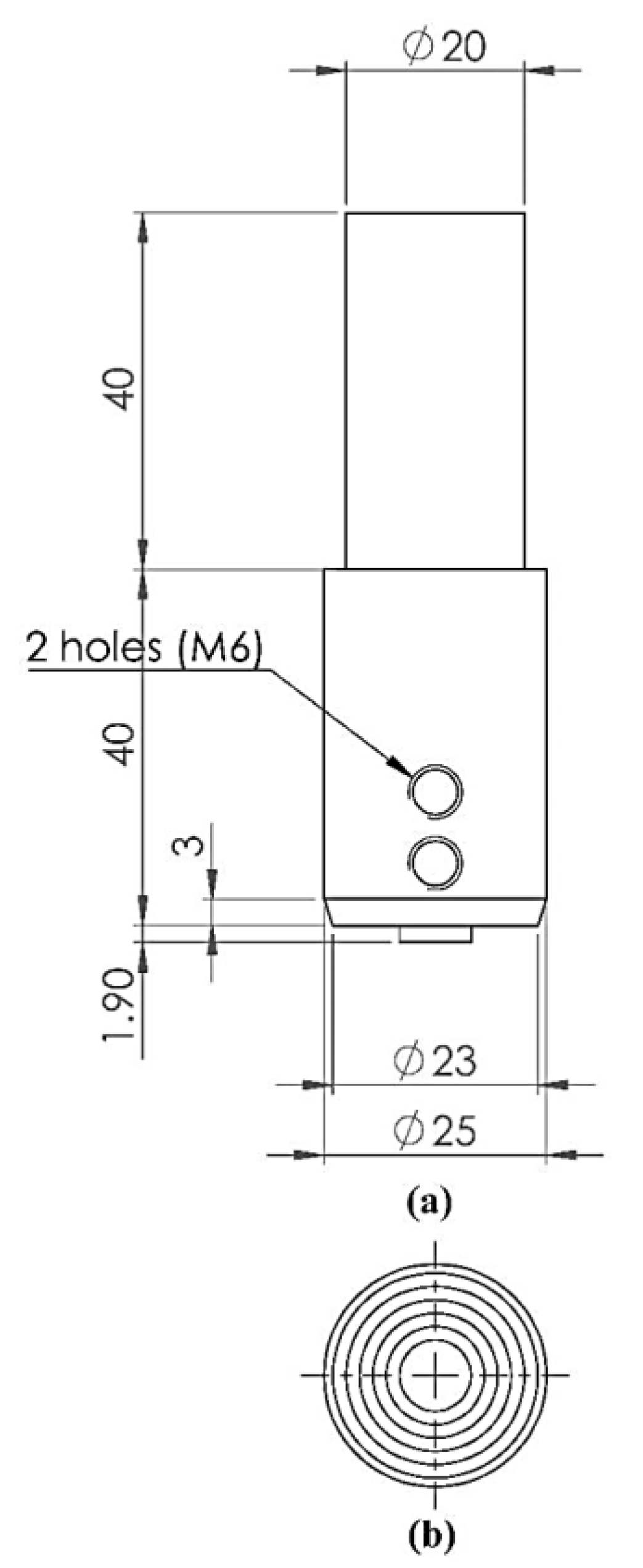
2.2. Sample Preparation and Electrochemical Test

The five selected cladded samples, were then sectioned and prepared for microstructural, microhardness, X-Ray diffraction (XRD), and corrosion resistance evaluation. The samples were extracted from the steady-state section from the middle of the cladded workpiece. Standard sample preparation for microstructural analyses was followed. Cladded samples were sectioned across the tool traverse motion and mounted using a cold molding technique to avoid any tempering/aging effect. The mounted samples were then grounded using SiC papers of 240 to 600 grit sizes. These samples were thereafter polished and etched. A two-step etching procedure was adopted for revealing the grains according to the technique proposed by Taheri [19]. The technique involved a pre-etching step whereby the samples were etched in a solution of 1 g of NaCl in 50 mL of 40% H3PO4 at an elevated temperature of 70 °C for a duration of approximately 5 min before etching in Weck’s solution consisting of 1 g of NaOH and 4 g of KMnO4 in 100 mL of H2O, for a similar duration.
Thereafter, the samples were examined under a digital optical microscope (DSX510 upright microscope, Olympus, Tokyo, Japan). The microhardness of the processed surface was then measured using a micro-indentation hardness tester (MicroCombi, CSM Instruments, Peseux, Switzerland), with an applied load of 500 mN, and 10 s dwell time. A multipurpose X-ray diffraction (XRD) apparatus (Ultima IV, Rigaku, Tokyo, Japan) was used to analyze the structural evolution of the cladded systems. The XRD samples were of the same thickness and were placed on the sample holder ensuring that they were aligned properly with the sample holder. The XRD was conducted to study if the process conditions resulted in phase variation, as well to estimate the average grain size using Scherrer’s formula as presented in Equation (1).
Average grain size = (0.9 × λ)/(FWHM × cosθ)
where 0.9 is the shape factor (spherical shape assumed), λ is the wavelength of the X-ray used (λCuKα = 0.154059 nm), FWHM is the full width at half maximum height, and θ is the Bragg’s angle.
Corrosion tests were conducted in a saline environment with 3.5 wt.% aerated aqueous sodium chloride (3.5% NaCl) solution as the electrolyte, where the processed surfaces of the cladded systems were covered with an electrochemical mask (GAMRY, Warminster, PA, USA) with a circular area of 1 cm2 to define a specific area for the analysis. All corrosion tests were conducted at room temperature using the typical Gamry flat cell. The electrochemical data were collected using a potentiostatic/galvanostatic instrument (Gamry 600, GAMRY, Warminster, PA, USA). The electrochemical cell used consisted of the cladded steel sample as the working electrode, a graphite rod as the counter electrode, and the saturated calomel electrode (SCE) was used as the reference electrode. The protective behavior against corrosion was studied by conducting electrochemical impedance spectroscopy (EIS) analysis with a frequency range between 100 kHz and 10 mHz. The number of points taken was 10/decade with an AC voltage of 10 mV. The effect of immersion durations of 1, 7, and 21 days was also investigated using the EIS technique. Data fitting and electrochemical simulations were carried out using the Echem Analyst software (Gamry, version 6.04) Potentiodynamic polarization (PDP) was performed after 21 days of continuous immersion in the saline medium. The potential was scanned from −0.25 V to 0.25 V with respect to the open circuit potential (OCP) at a potential sweep rate of 1 mVs−1. After the 21 days exposure duration and the corrosion (EIS and PDP) measurements, the exposed surfaces were characterized using scanning electron microscopy (SEM) coupled with energy dispersive spectroscopy (EDS). Both techniques were applied to study the corroded surface morphology and developed corrosion products on the processed surface and unprocessed cladded material.

3. Results and Discussion

3.1. Dependent Process Variables and Heat Input

A number of process variables were monitored during the FSDC process. These parameters included tool reaction forces, torque as well as plunging depth, tool location, and feed rate. The estimation of heat input can be calculated following ASME (BPVC) Section IX-Welding [20]. Equation (2) evaluates the heat input per unit length of the weld.
H = (P/v) = (T × w)/v
where H represents the heat input in J/mm, P power in watt, v is the traverse speed in mm/s, T is tool torque N.m, and ω is tool angular speed in rad/sec. In this equation, heat transfer efficiency is ignored, and 100% of the mechanical work is assumed to convert into heat. Note that heat generated due to tool advancing was also ignored. Table 3 presents the tool advance per revolution (APR), the average measured values of tool forging force and torque, while the heat input evolution is presented in Figure 2. It can be seen that the heat input for samples FM-2 and FL-1 is relatively close, but forging force is higher for sample FM-2. This explains the difference in joint strength as reported in Table 1. The full characterization of the aluminum-steel interfacial bonding has been reported in [4], it also discusses the formation of intermetallic layer at the joint between the clad material and the base. For sample FM-2, the average thickness of the intermetallic layer was around 4 µm, while for sample FL-1, the average thickness was around 2.5 µm [4].

3.2. Microstructure Analysis

Optical images of the representative FSDC processed samples are shown in Figure S1 (supplementary data). Due to frictional heat and dynamic stirring action, the cladded material experiences extreme plastic deformation, which results in dramatic changes in the microstructure. In friction stir welding and processing, it is well-known that three distinct regions are usually generated i.e., the stir zone (SZ) (also known as the weld nugget), the thermomechanical-affected zone (TMAZ), and the heat-affected zone (HAZ). These are usually visible in the weldment cross-section. In this work, the processed surface was more of an interest to study rather than the cross-section or bond interface as this zone will be exposed to the corrosive environment and act as a physical barrier to the substrate. Figure 3a illustrates the panoramic macrostructure view of sample FL-1, where the flow lines can be observed. It also shows the processed and unprocessed zones near the advancing side. These features are generated from the rotational extrusion action by the FSW tool. In a study by Fu et al. [21], the authors described the microstructure of a processed surface in FSW of AA2524 aluminum alloys with Al cladding, and described the flow lines occurring at the advancing side as an “arc strip”. It was mentioned in the study that the microstructure of the top surface differs from that of the weld cross-section, and the “arc strip” replaces the onion ring features that appear at the weld cross-section. High magnification optical microscopy images of the samples are shown through Figure 3b–g. It is generally observed that the processed surface is free from defects, such as porosity and cracks that are typical of FSW at certain process parameters. Furthermore, the impact of the process conditions on the developed surface microstructure was not immediately revealed. As the material was severely deformed, the grain’s boundary was not fully seen after etching. Therefore, optical microscopy images were not sufficient to explain the effect of the process parameters on the developed surface microstructure.
Figure 4a presents XRD patterns for the processed samples as well as the unprocessed Al metal. Figure 4b,c are zoomed-in figures of the (111) and (200) peaks showing the diffraction angles. The main phase formed was α-Al. While the peaks were identical, their intensities were varied, which indicates the absence of a new phase formation during the process. However, the dominant peak was changed after processing. The dominant peak for unprocessed alloy was (200), but after processing (111) was dominant in all processed samples. This indicates the effect of the dynamic stirring on the preferred diffraction plane. The preferential diffraction plan prior to FSDC processing was the (200) and (220) planes. However, after processing, the (111) plane was preferred for diffraction.
Scherrer’s equation was used to estimate the average crystal size. It should be noted that since the instrumental broadening was not deconvoluted from the diffraction pattern, the estimated crystallite size will be the minimum possible value, this is coupled with the possibility of the crystal size being in the micrometer range. Thus, the crystal size obtained from Scherrer’s equation might have been significantly underestimated, and is only used in this study for a relative and comparative qualification. From the results shown in Figure 5, the estimated average crystal size was based on the (111) and (200) peaks. The crystal size of the unprocessed Al cladding material ranges between 50 and 70 nm. Upon cladding, the crystallite size for samples FM-3 and FL-1 reduced by 20% and 10%, respectively, while for samples FM-2 and FH-1, the crystallite size slightly increased by 16% and 6%, respectively. However, a significant increment of about 45% was observed for sample FM-1. According to the trend shown in Figure 5, the initial increase in the crystal size with a traverse speed of 50 mm/min can be attributed to recrystallization and subsequent grain growth. This can be associated with the high heat input at lower traverse speed. However, as the traverse speed increases to 100 and 150 mm/min, the crystallite size decreases further, a consequent from the decrease in the heat input as shown in Figure 2. At high traverse speeds, the APR is higher, which indicates that a large volume of material is processed as the tool progresses forward making the generated frictional heat lower and thus the attendant temperature at the rubbing interface lower for recrystallization or not sufficient for grain growth to occur. Similarly, increasing the rotation speed induced more heat input and hence the crystallite size at a low rotation speed of 250 rpm was just lower as compared to the unprocessed Al cladding metal. This is because the generated heat at 250 rpm was sufficient to cause grain refinement due to the dynamic plastic deformation. However, as the rotation speed increased to 500 rpm, higher heat input may have induced an increased degree of recrystallization and crystallite growth. It is also worth noting that the amount of plastic deformation induced (sensible from the plunging forces shown in Table 2) can also influence recrystallization temperature and crystallite growth. At a higher rotation speed, it is observed that the crystallite size reduces slightly. This may be due to the severe plastic deformation at the higher rotation speed at the expense of the effect of the high heat input. Additionally, the peaks were observed to have shifted to lower diffraction at all process conditions as shown for the (111) and (200) peaks in Figure 4b,c, respectively. The shift of the diffraction angle as a function of traverse and rotational speed are shown in Figure S2 (supplementary data). The peak shift to lower diffraction angles shows that the induced compressive planar stress because of the severe dynamic plastic deformation increases with traverse and rotation speeds. However, the shift due to rotation speed is more drastic as compared to that from the traverse speed. This is expected due to the lower APR at higher rotation speed as less material is processed as the tool rotates and progresses forward.
The hardness of the cladded system measured with the microindentation from the processed top surface is shown in Figure 6. The load versus the penetration depth curves are provided in the supplementary data file (Figure S3). As the rotation speed increased from 250 to 500 to 1000 rpm, the hardness increased from 915 MPa for the unprocessed Al cladding material by 26%, 6%, and 3%, respectively. The relatively lower hardness at higher rotation speed can be attributed to crystallite growth due to higher heat input. Similarly, the hardness increased slightly by 6%, 20%, and 15% when the traverse speed was increased to 50, 100, and 150, respectively. The hardness trend agrees well with the crystallite size presented in Figure 5. The Al 5052 alloy is non-heat treatable and is hardened by the cold-work process. Thermal stabilization treatment is usually used to stabilize the gained hardness and to avoid time-dependent age softening [22]. Annealing of 5052 Aluminum alloy is achieved by uniformly increasing the temperature of the workpiece to 345 °C [23]. In the FSDC process, similar to FSW, the processed material temperature is expected to reach 80% of the solidus temperature, which is above the annealing temperature. Therefore, partial annealing can be expected, i.e., softening of the processed material. Besides the crystallite growth phenomenon, this is another possible explanation for the drop in the hardness of samples that were processed at a higher rotation speed, where heat input was highest. Generally, the hardness of the friction stir processed surface is usually influenced by the recrystallization and heating cycle, among other phenomena.

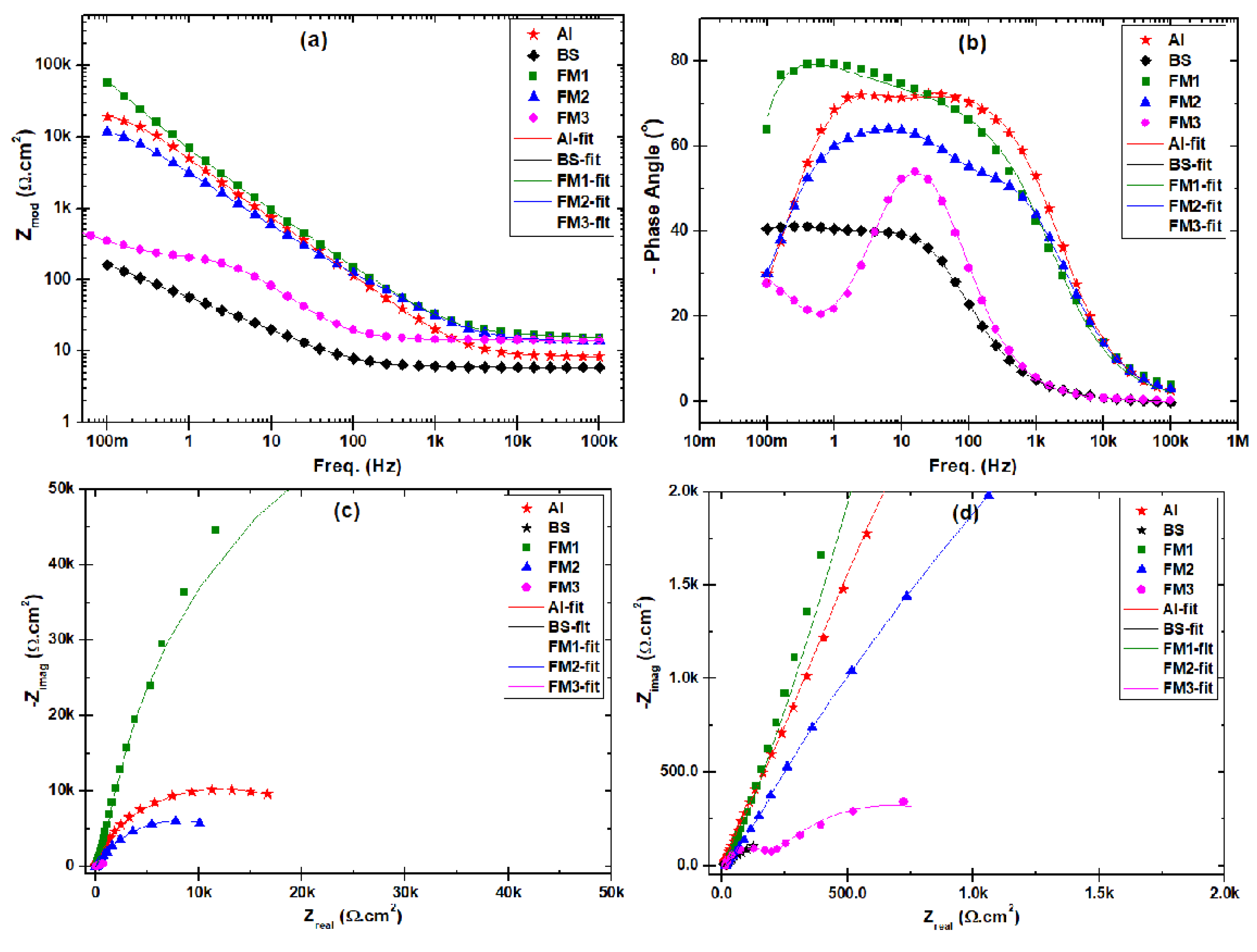
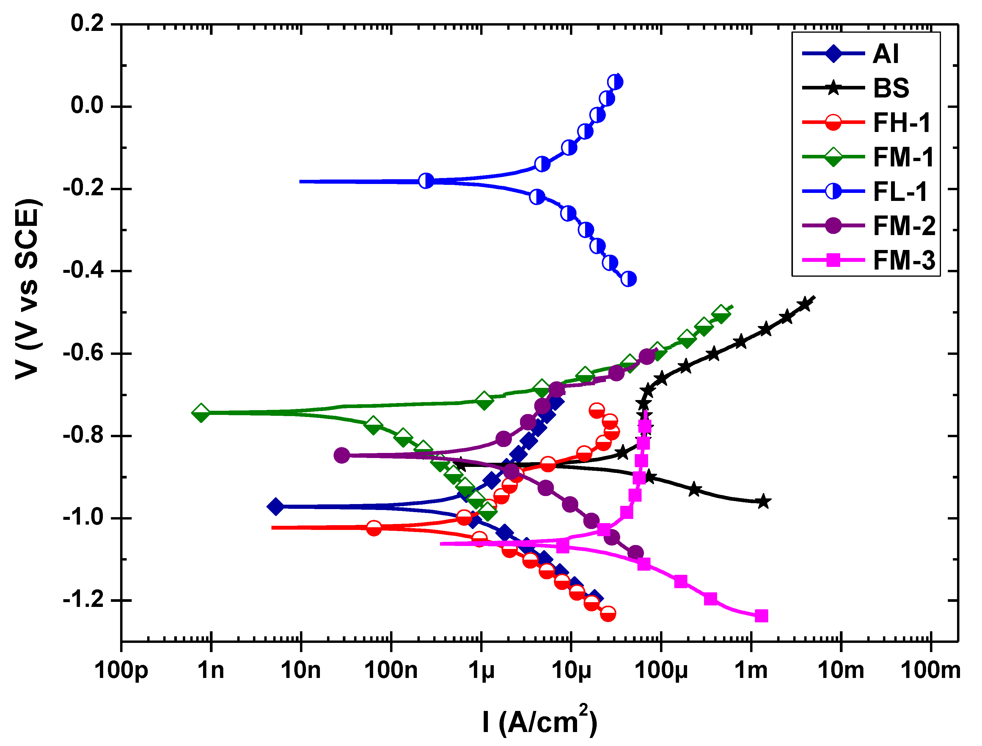
3.3. Corrosion Behavior

The corrosion behavior evaluation of the samples was investigated using the EIS technique after immersion duration of 21 days (3 weeks). The EIS test was conducted in 3.5 wt.% aqueous sodium chloride (NaCl) solution for the unprocessed (as-received) Al 5052-H32, bare steel substrate, and cladded samples (FSDC-processed). Figure 7a–d show EIS modulus, phase, Nyquist, and zoomed-in Nyquist plots, respectively, for samples FL-1, FM-1, and FH-1 to evaluate the impact of tool rotational speed at a fixed traverse speed. From the modulus curve (Figure 7a), it is evident that the cladded samples at different rotation speeds demonstrated higher corrosion resistance than that of the bare steel, which is aimed to be protected. The FM-1 sample exhibited superior resistance, while FH-1 also offered higher resistance as compared to the unprocessed Al metal. However, the corrosion resistance of FL-1 was lower than the unprocessed Al metal, which indicates that lower rotation speed during FSDC deteriorates the corrosion-resistance properties of the Al cladding material. This may be related to the reduced crystallite size (as shown in Figure 5), which means higher grain boundary defects in the FSDC processed material that serves as a path for corrosive ions to penetrate the Al cladding. Similar behavior has been reported in an earlier study by Ralston et al. [24], in which the corrosion rate of pure aluminum in neutral NaCl tends to decrease upon decreasing the grain size. Phase angles of cladded samples were also found to be high and close to 80° when compared to bare steel and unprocessed clad alloy. One can notice that the phase angle for sample FM-1 is high over a wide range of frequencies and the maximum occurs at low-frequency values compared to other process conditions. Additionally, unlike the bare steel, it can be observed that the cladded samples demonstrated a two-time constant behavior identifiable by the points of inflection from the EIS curves. The Nyquist plot (Figure 7c,d) reveals an incomplete semicircle, and the radius of the semicircle for the cladded samples is significantly larger than that of the bare steel and unprocessed Al cladding material.
Figure 8 presents the EIS curves after 21 days of immersion for cladded samples FM-1, FM-2, and FM-3 in addition to bare steel and the unprocessed Al cladding material for comparison. Although, all cladded samples exhibited a higher impedance that was larger than bare steel, samples FM-2 and FM-3 demonstrated lower resistance in comparison to the unprocessed Al cladding material. Moreover, the impedance of sample FM-3 was just slightly higher than the impedance of the bare steel (Figure 8a). This indicates that the selected process parameters induced a negative influence on the corrosion resistance of the Al cladding material. This may also be associated with the reduced crystallite size of the samples processed at higher traverse speeds. The phase angle (Figure 8b) of FM-1 was the only sample with a larger phase angle than the cladding material and was close to 80°. The Nyquist plot (Figure 8c) also revealed a semicircle at high frequencies for the bare steel, FM-2, and FM-3 samples, while the large incomplete semicircle of sample FM-1 also further supports its superior resistance. By zooming in as in Figure 8d, it is clearly seen that the cladded samples FM-2 and FM-3 exhibited a lower resistance relative to the unprocessed Al cladding material. The results indicate the superiority of sample FM-1 over the other samples in terms of corrosion resistance including unprocessed cladding material. Besides the fact that grain refinement can influence the corrosion resistance for low-to-passive alloys, it may also affect the thermo-mechanical properties that may affect the corrosion resistance. These include but are not limited to developed surface roughness, segregation of alloying elements, porosity (defects), and/or internal stresses [25]. It should be noted that the corrosion test was performed on the unprocessed Al metal to serve as a measure of deviation due to the FSDC processing. However, they are not practically comparable, as the corrosion of the cladded system with processed Al top surface and steel being the substrate cannot be likened to that of a freestanding unprocessed Al metal.
For further insight into the corrosion behavior, the EIS data were fitted with the appropriate equivalent circuit. Excellent agreement between the fitted and experimental EIS data was obtained. Figure 9 illustrates the equivalent electrical circuits used to fit the EIS data of bare steel and cladded samples after 21 days of immersion as well as the unprocessed clad material. The circuits consist of a constant phase element (CPEdl) to account for double-layer capacitance, in parallel with charge transfer resistance (Rct). For the cladded system, an additional constant phase element (CPEcl) with a resistance (Rcl) were added to represent the additional capacitive behavior and impedance, respectively, generated by the cladding material on the top of the substrate; as shown in Figure 9. Constant phase elements (CPEu) in parallel to resistance (R) were added to simulate the oxides layer-either those physisorbed on the bare steel or those formed on the cladded system. Electrochemical parameters extracted from the EIS fitting are presented in Table 4. The FSDC processed samples’ efficiency (Eeis) was calculated according to Equation (3).
Eeis = ((Rct/pRct/s)/Rct/p) × 100
Where Rct/p and Rct/s are the charge transfer resistances for the steel-Al cladded samples and the steel substrate, respectively.
It can be noticed that the charge transfer resistance (Rct) component in all cladded samples is higher than the bare steel, and this indicates that the process was successful in protecting the substrate. The increase in the charge transfer resistance demonstrates an improved bonding between the steel substrate and Al cladding material, which resists the penetration of the ions. It is also observed that based on the Rct, the processed samples’ efficiency (Eeis), when compared to bare steel, ranges between 92.0% and 99.7% except for FM-3, which has an efficiency of about 53.0%. Furthermore, sample FM-1 showed a less dielectric behavior in comparison to other cladded samples that offered enhanced capacitive behavior as observed from the CPEcl in Table 4. The resistance to corrosion by the cladding as indicated by Rcl shows that as the traverse speed is increased the cladding corrosion resistance (Rcl) increases, however, the Al-steel interface resistance (indicated by Rct) shows an opposite trend. This further substantiates the importance of the bonding and lack of defects at the Al-steel interface for improved corrosion resistance. All the cladded samples show higher total resistance and thus better protection as compared to steel. Although, samples FM-2, FM-1, and FL-1 were lower than the unprocessed Al cladding material (Figure 10), they still offer enhanced corrosion resistance compared to the steel substrate. Generally, the intermediate rotational speed is found to result in better corrosion performance, which is found to be matching with the bonding strength and mechanical properties reported in [4]. The variation can be attributed to both dynamic stirring and recrystallization as a result of optimum heat generation and utilization during the cladding process.
Potential dynamic polarization (PDP) was performed after 21 days of immersion in the saline medium, and the results are shown in Figure 10. The data extracted from the PDP curves are also listed in Table 5. Based on the Icorr obtained from the PDP test, the FSDC-processed-sample efficiency (Epdp) was estimated using Equation (4).
Epdp = ((Icorr/sIcorr/c)/Icorr/s) × 100%
Where Icorr/c and Icorr/s are the current densities of the cladded samples and the steel base substrate (BS), respectively. All cladded samples show lower corrosion current (Icorr) as compared to bare steel, while the lowest was found for sample FM-1. It is noticed that the corrosion potential (Ecorr) decreased with increasing traverses speed while fixing the rotational speed resulted in decreasing the corrosion potential. Similarly, increasing the tool rotational speed resulted in decreasing the corrosion potential. On the other hand, the corrosion rate was about 3.4 µA/cm2 at a low rotation speed of 250 rpm, however, it reduced on increasing the rotation speed to 500 rpm. This corresponds to the EIS results and the crystallite size trend. At a higher rotation speed of 1000 rpm, the corrosion rate drops slightly again but is still higher than the unprocessed Al cladding material and the bare steel substrate. It was noticed that increasing the tool traverse speed resulted in an increase in the corrosion current (Icorr). Murugan et al. [26] have reported similar findings on the corrosion current of dissimilar aluminum to stainless steel friction stir welds, and the behavior was explained by the impact of tool traverse speed on grain refinement. Rambabu et al. [27] investigated the effect of FSW process parameters on the corrosion resistance of Al 2219 alloy: they reported that high and low levels of tool rotational speeds (1400 and 1000 rpm) resulted in a degradation in the corrosion resistance, while a low welding (traverse speed) i.e., 600 mm/min resulted in the best corrosion resistance.
Passivation behavior of the Al alloy helps protect the material from localized pitting corrosion, which is very essential in chloride and saline environments. Passivation is among the corrosion protection mechanisms of aluminum alloys, and the cladding material grade (Al 5052-H32) has good corrosion resistance and passivation properties, thus it is recommended for the marine environment [17,18]. Therefore, the pitting-resistance properties of the samples were observed from the anodic polarization curve. It should be noted that there was no significant influence of the process parameters on the cathodic polarization curve. Nevertheless, there was a significant effect on the anodic corrosion behavior. As the rotation speed increased, the anodic corrosion protection improved and the samples become more passive. Sample FM-1, with the lowest corrosion rate, lost the passivity tendency of the Al cladding material, as can be observed by the sharp and continuous increase in the anodic current density for any small potential polarization. Sample FM-2 exhibited similar passivation as the unprocessed Al cladding material, but there was a rapid breakdown of passivity. Interestingly, sample FM-3 with a higher corrosion rate than the Al cladding material became the most passive, with the anodic curve almost being vertical indicating almost no increase in the current density at large polarization of the potential. Contrastingly, an increase in the traverse speed caused an attendant reduction in the anodic corrosion, which illustrates a rapid breakdown of the passivity of the sample. Sample FH-1 exhibited a continuous increase in the anodic polarization curve similar to FM-1. However, the passivation behavior of the Al cladding material was slightly improved for sample FL-1 with significant enhancement of its nobility. Therefore, it is observed that samples FM-3 and FL-1 demonstrated superior pitting resistance behavior by improving the stability of the passivity. This observation can be associated with the crystallite size, which reduction favors the formation of a passive layer due to increases in surface energy sequential to the increased number of grain boundaries [28]. This is found to be consistent with reports in the literature [29,30]. Ralston and Birbilis [29] made a survey on the effect of grain refinement on susceptibility to corrosion. In their report, grain refinement in 5xxx aluminum alloys under specific refinement techniques was found to improve corrosion resistance. Furthermore, in a recent study by Anas et al. [30], corrosion resistance was found to increase with a reduction in crystal size. Similarly, Moeini et al. [31] reported enhancement in corrosion resistance in underwater FSP as compared to in-air FSP of additive manufactured Al-Si 12, due to a higher cooling rate that led to a more corrosion-resistant microstructure. The corrosion-protection mechanism may vary between metals and alloys, with finer grains resulting in increasing surface energy, therefore it can be a positive for surfaces that build a passive layer and at the same time a negative [28]. Moreover, the percentage of Mg in Al 5xxx may result in reducing the corrosion resistance due to the formation of AlMg β phase [32].

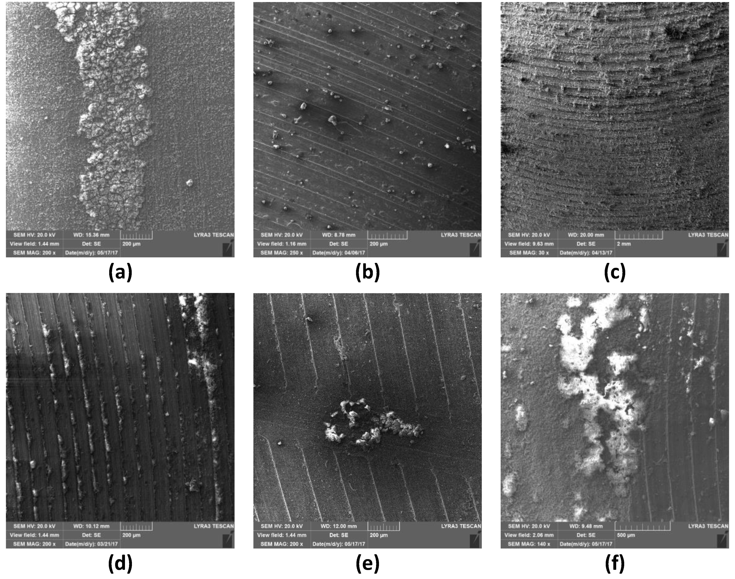
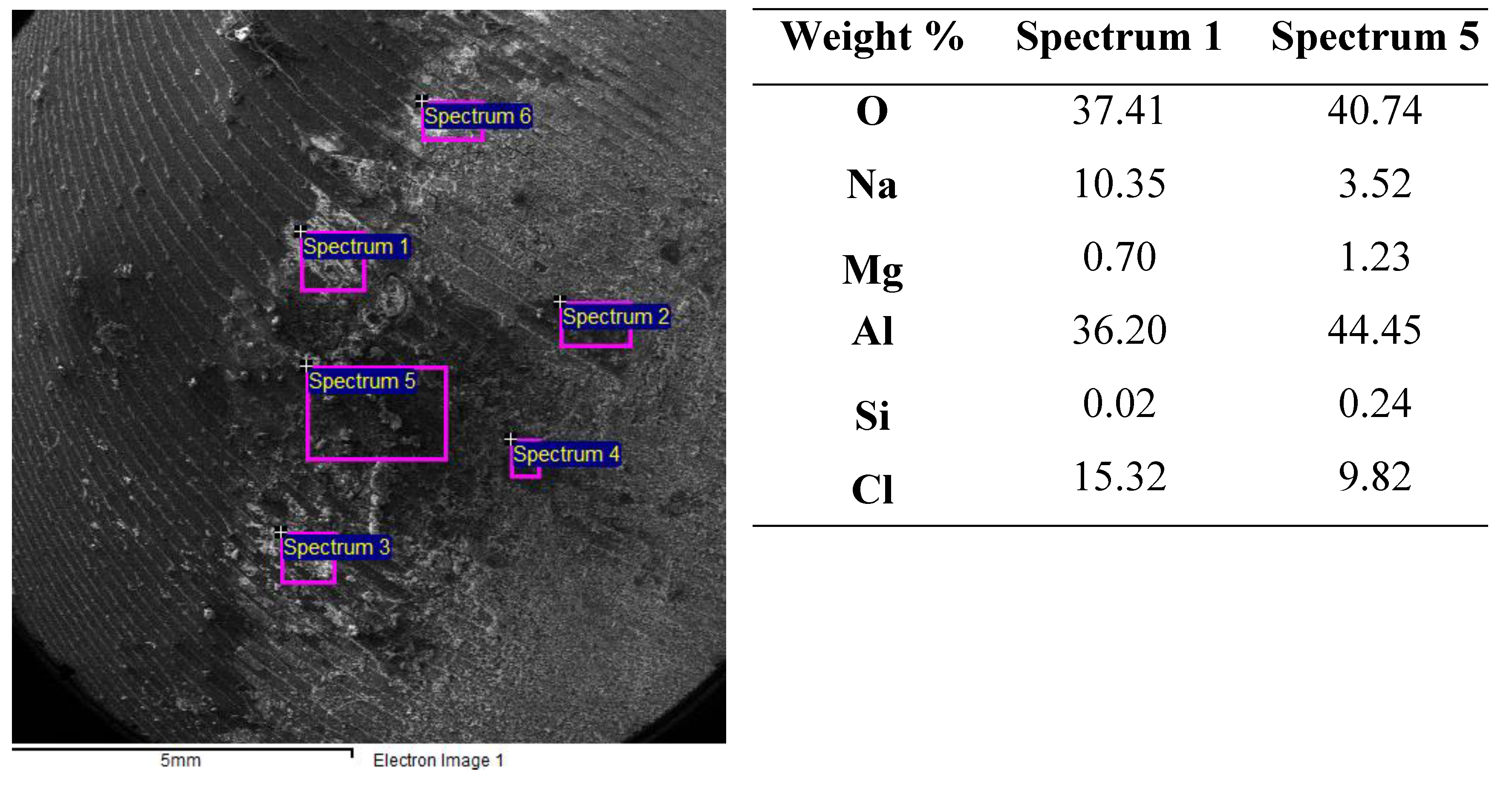
3.4. Surface Examination after Corrosion

After completing the corrosion tests, the corroded surfaces of the cladded samples, as well as unprocessed cladding material were examined using SEM, and the corrosion products were also analyzed using EDS analyses. The low magnification SEM images showing the exposed area to the medium are provided in Figure S4 (supplementary data). The ranks of the corrosion protection performance of all samples obtained from the EIS analysis, PDP, and visual inspection of the corroded surfaces were found to be in good agreement. Figure 11 presents the SEM images of the exposed areas. Besides the unprocessed Al (Figure 11a), significant accumulation of corrosion products can be observed on the samples with samples FL-1 (Figure 11c) and FM-3 (Figure 11f) exhibiting improved passivation behavior. Figure 12 presents the EDS results of the corroded sample FL-1. It can be inferred from the results that the corrosion products are possible mixtures of oxides of Al, Mg, or combination and NaCl deposits. The formation of the corrosion product can hinder further corrosion of the underlying metal when the formed oxides are well dispersed, compact, and firmly adherent oxides. This is indicated by the almost vertical anodic curve (better passive region stability) of sample FM-3 as well as sample FL-1 after being anodically polarized to higher potentials.

4. Conclusions

In this work, the effect of FSDC process parameters on the corrosion protection of cladded system AA 5052-H32/ASTM A516-70 was studied. Both EIS and PDP electrochemical techniques were used to study the corrosion resistance of the cladded system as compared to bare steel. In summary, the cladded system exhibited enhanced corrosion resistance in a 3.5% NaCl environment as compared to bare steel under all processing conditions. This indicates the great impact of process parameters on the corrosion protectiveness of the cladding system. Based on the experimental results, the following conclusions can be drawn:
  • The FSDC processing of steel substrate minimized its corrosion rate, which was found to be dependent on processing parameters.
  • Optimum process conditions for general corrosion resistance were found to be for medium tool rotational speed and low traverse speed. While improvement of passivity of the cladded system occurred at medium traverse speed and high traverse speed.
  • EIS and PDP results revealed that the general corrosion resistance decreases upon increasing the traverse speed.
  • An intermediate tool rotational speed of 500 rpm resulted in optimum value for anticorrosion properties, while the passivation property was improved at the rotational speed of 1000 rpm and traverse speeds of 50 mm/min.

Supplementary Materials

The following are available online at https://www.mdpi.com/2075-4701/10/5/623/s1: Figure S1: Optical images of typical FSDC processed samples for FH-1 (A50), FM-1 (B50), and FL-1 (C50); Figure S2: Diffraction angles of the (111) peak showing the shift to lower angles as a function of rotation and traverse speeds; Figure S3: Load vs penetration depth curves for unprocessed Al and FSDC samples.; Figure S4: Low magnification SEM images of corroded surfaces.

Author Contributions

Conceptualization, F.A.A.-B.; methodology, F.A.A.-B. and R.K.S.; formal analysis, A.Y.A.; investigation, A.Y.A. and A.B.I.; data curation, A.A.S. and N.M.; writing—original draft preparation, F.A.A.-B.; writing—review and editing, A.Y.A., A.B.I., and R.K.S.; visualization, F.A.A.-B., A.Y.A., and A.B.I.; supervision, F.A.A.-B. All authors have read and agreed to the published version of the manuscript.

Funding

This research was funded by King Fahd University of Petroleum and Minerals, grant number IN161049.

Acknowledgments

The authors would like to thank King Fahd University of Petroleum and Minerals (KFUPM, Dhahran, Saudi Arabia) for providing all support to this project. This project has been funded by King Fahd University of Petroleum and Minerals under project no. IN161049.

Conflicts of Interest

The authors declare no conflict of interest. The funders had no role in the design of the study, in the collection, analyses, or interpretation of data, in the writing of the manuscript, or in the decision to publish the results.

References

  1. Buchanan, V.; Shipway, P.; McCartney, D. Microstructure and abrasive wear behaviour of shielded metal arc welding hardfacings used in the sugarcane industry. Wear 2007, 263, 99–110. [Google Scholar] [CrossRef]
  2. Rao, K.P.; Ram, G.J.; Stucker, B. Effect of friction stir processing on corrosion resistance of aluminum–copper alloy gas tungsten arc welds. Mater. Des. 2010, 31, 1576–1580. [Google Scholar] [CrossRef]
  3. Mabuwa, S.; Msomi, V. Review on Friction Stir Processed TIG and Friction Stir Welded Dissimilar Alloy Joints. Metals 2020, 10, 142. [Google Scholar] [CrossRef] [Green Version]
  4. Ibrahim, A.B.; Al-Badour, F.A.; Adesina, A.Y.; Merah, N. Effect of process parameters on microstructural and mechanical properties of friction stir diffusion cladded ASTM A516-70 steel using 5052 Al alloy. J. Manuf. Processes 2018, 34, 451–462. [Google Scholar] [CrossRef]
  5. Al-Badour, F.; Merah, N.; Mohamed, O.; Bazoune, A.; Shuaib, A. Optimizing Process Conditions in Friction Stir-Diffusion Lap Welding of Aluminum Alloy With Cold Rolled Steel. In Proceedings of the ASME 2018 13th International Manufacturing Science and Engineering Conference, College Station, TX, USA, 18–22 June 2018. [Google Scholar] [CrossRef]
  6. Ibrahim, A.B.; Al-Badour, F.A.; Suleiman, R.; Adesina, A.Y.; Sorour, A.A. Friction Stir Diffusion Cladding of 5052 Aluminum Alloy on Cold-Rolled Carbon Steel. In Proceedings of the 17th Middle East Corrosion Conference and Exhibition, Manama, Bahrain, 3 October–30 November 2018; pp. 1–13. [Google Scholar]
  7. Argade, G.; Shukla, S.; Liu, K.; Mishra, R. Friction stir lap welding of stainless steel and plain carbon steel to enhance corrosion properties. J. Mater. Process. Technol. 2018, 259, 259–269. [Google Scholar] [CrossRef]
  8. Shen, Z.; Chen, Y.; Haghshenas, M.; Nguyen, T.; Galloway, J.; Gerlich, A. Interfacial microstructure and properties of copper clad steel produced using friction stir welding versus gas metal arc welding. Mater. Charact. 2015, 104, 1–9. [Google Scholar] [CrossRef]
  9. Li, B.; Shen, Y.; Luo, L.; Hu, W. Effects of processing variables and heat treatments on Al/Ti-6Al-4V interface microstructure of bimetal clad-plate fabricated via a novel route employing friction stir lap welding. J. Alloys Compd. 2016, 658, 904–913. [Google Scholar] [CrossRef]
  10. Li, H.; Qin, W.; Galloway, A.; Toumpis, A. Friction surfacing of aluminium alloy 5083 on DH36 steel plate. Metals 2019, 9, 479. [Google Scholar] [CrossRef] [Green Version]
  11. Davis, J.R. Stainless Steels; ASM international: Novelty, OH, USA, 1994. [Google Scholar]
  12. Bajakke, A.; Jambagi, C.; Malik, R.; Deshpande, S. Friction Stir Processing: An Emerging Surface Engineering Technique. In Surface Engineering of Modern Materials. Engineering Materials; Gupta, K., Ed.; Springer: Cham, UK, 2020. [Google Scholar] [CrossRef]
  13. Xu, W.; Liu, J. Microstructure and pitting corrosion of friction stir welded joints in 2219-O aluminum alloy thick plate. Corros. Sci. 2009, 51, 2743–2751. [Google Scholar] [CrossRef]
  14. Surekha, K.; Murty, B.; Rao, K.P. Microstructural characterization and corrosion behavior of multipass friction stir processed AA2219 aluminium alloy. Surf. Coat. Technol. 2008, 202, 4057–4068. [Google Scholar] [CrossRef]
  15. Surekha, K.; Murty, B.; Rao, K.P. Effect of processing parameters on the corrosion behaviour of friction stir processed AA 2219 aluminum alloy. Solid State Sci. 2009, 11, 907–917. [Google Scholar] [CrossRef]
  16. Surekha, K.; Murty, B.; Rao, K.P. Comparison of corrosion behaviour of friction stir processed and laser melted AA 2219 aluminium alloy. Mater. Des. 2011, 32, 4502–4508. [Google Scholar] [CrossRef]
  17. Shamsudeen, S.; John, E.R.D. Effect of Welding on Pitting and Intergranular Corrosion Behavior of Marine Grade Aluminum Alloy. Mater. Perform. Charact. 2019, 8, 555–570. [Google Scholar] [CrossRef]
  18. Shanavas, S.; Dhas, J.E.R.; Murugan, N. Weldability of marine grade AA 5052 aluminum alloy by underwater friction stir welding. Int. J. Adv. Manuf. Technol. 2018, 95, 4535–4546. [Google Scholar] [CrossRef]
  19. Mohammadtaheri, M. A new metallographic technique for revealing grain boundaries in aluminum alloys. Metall. Microstruct. Anal. 2012, 1, 224–226. [Google Scholar] [CrossRef] [Green Version]
  20. ASME. BPVC Section IX-Welding, Brazing and Fusing Qualifications; ASME: New York, NY, USA, 2017. [Google Scholar]
  21. Fu, R.; Xu, H.; Luan, G.; Dong, C.; Zhang, F.; Li, G. Top surface microstructure of friction-stir welded AA2524-T3 aluminum alloy joints. Mater. Charact. 2012, 65, 48–54. [Google Scholar] [CrossRef]
  22. Kaufman, J.G. Introduction to Aluminum Alloys and Tempers; ASM International: Novelty, OH, USA, 2000. [Google Scholar]
  23. Atlas Steel Documents. Available online: http://www.atlassteels.com.au/documents/Atlas_Aluminium_datasheet_5052_rev_Oct_2013.pdf (accessed on 3 February 2020).
  24. Ralston, K.; Fabijanic, D.; Birbilis, N. Effect of grain size on corrosion of high purity aluminium. Electrochim. Acta 2011, 56, 1729–1736. [Google Scholar] [CrossRef]
  25. Ralston, K.; Birbilis, N.; Davies, C. Revealing the relationship between grain size and corrosion rate of metals. Scr. Mater. 2010, 63, 1201–1204. [Google Scholar] [CrossRef]
  26. Murugan, B.; Thirunavukarasu, G.; Kundu, S.; Kailas, S.V. Influence of tool traverse speed on structure, mechanical properties, fracture behavior, and weld corrosion of friction stir welded joints of aluminum and stainless steel. Adv. Eng. Mater. 2019, 21, 1800869. [Google Scholar] [CrossRef]
  27. Rambabu, G.; Naik, D.B.; Rao, C.V.; Rao, K.S.; Reddy, G.M. Optimization of friction stir welding parameters for improved corrosion resistance of AA2219 aluminum alloy joints. Defence Technol. 2015, 11, 330–337. [Google Scholar] [CrossRef] [Green Version]
  28. Gollapudi, S. Grain size distribution effects on the corrosion behaviour of materials. Corros. Sci. 2012, 62, 90–94. [Google Scholar] [CrossRef]
  29. Ralston, K.; Birbilis, N. Effect of grain size on corrosion: A review. Corrosion 2010, 66, 075005–075013. [Google Scholar] [CrossRef]
  30. Anas, N.; Abioye, T.; Anasyida, A.; Dhindaw, B.; Zuhailawati, H.; Ismail, A. Microstructure, mechanical and corrosion properties of cryorolled-AA5052 at various solution treatment temperatures. MRE 2020, 7, 016535. [Google Scholar] [CrossRef]
  31. Moeini, G.; Sajadifar, S.V.; Engler, T.; Heider, B.; Niendorf, T.; Oechsner, M.; Böhm, S. Effect of Friction Stir Processing on Microstructural, Mechanical, and Corrosion Properties of Al-Si12 Additive Manufactured Components. Metals 2020, 10, 85. [Google Scholar] [CrossRef] [Green Version]
  32. D’Antuono, D.S.; Gaies, J.; Golumbfskie, W.; Taheri, M. Grain boundary misorientation dependence of β phase precipitation in an Al–Mg alloy. Scr. Mater. 2014, 76, 81–84. [Google Scholar] [CrossRef]
Figure 1. The friction stir diffusion cladding (FSDC) tool (a) side view, (b) bottom view of tool shoulder, showing the grooves to enhance material’s flow during cladding. (All dimensions are in mm).
Metals 10 00623 g001
Figure 2. Variation of the heat input as a function of the rotation and traverse speeds.
Metals 10 00623 g002
Figure 3. Optical microscope images (a) panoramic view of processed zone, (b) unprocessed Al metal, (c) FL-1, (d) FH-1, (e) FM-1, (f) FM-2, and (g) FM-3. Letters L, M and H represent 250, 500, and 1000 rpm, respectively. Digits 1, 2, and 3 designate 50, 100, and 150 mm/min, respectively).
Metals 10 00623 g003
Figure 4. X-ray diffraction patterns: (a) all processed samples in comparison with base Al, (b) zoom in (111) plane, (c) zoom in (200) plane.
Metals 10 00623 g004
Figure 5. Crystallite size as a function of the traverse and rotation speeds.
Metals 10 00623 g005
Figure 6. Microindentation hardness of the stirred zone as a function of the rotational and traverse speeds.
Metals 10 00623 g006
Figure 7. Electrochemical impedance spectroscopy (EIS) curves: (a) modulus (b) phase angle (c) Nyquist plot and (d) zoomed-in plot of (c), showing the effect of rotation speed after 21 days of immersion in 3.5% NaCl medium.
Metals 10 00623 g007
Figure 8. EIS curves: (a) modulus (b) phase angle (c) Nyquist plot and (d) zoomed-in plot of (c), showing the effect of traverse speed after 21 days of immersion in 3.5% NaCl medium.
Metals 10 00623 g008
Figure 9. Equivalent circuits used for fitting the EIS data of the (a) bare steel and (b) cladded samples after 21-day immersion.
Metals 10 00623 g009
Figure 10. Potential dynamic polarization (PDP) curves showing the effect of rotation speed on the corrosion potential and current density after 21 days of immersion in 3.5% NaCl medium, (Al is the unprocessed Aluminum and BS is the steel base substrate).
Metals 10 00623 g010
Figure 11. SEM images of corroded surfaces of (a) unprocessed Al, (b) FH-1, (c) FL-1, (d) FM-1, (e) FM-2, and (f) FM-3 after 21 days of immersion.
Metals 10 00623 g011
Figure 12. Energy dispersive spectroscopy (EDS) analysis (of sample FL-1) after 21 days of immersion in 3.5% NaCl showing the composition of typical corrosion product.
Metals 10 00623 g012
Table 1. Elemental compositions of ASTM A516-70 pressure vessel steel substrate material and cladding 5052 Al Alloy.
MaterialsComposition (at.%)
CSiMnSPFeMgCrOthersAl
A516-70 Steel0.310.451.30.0350.035Bal.----
5052 Al alloy-0.290.086--0.3252.260.2470.029Bal.
Table 2. The FSDC process parameters used and the corresponding sample designation (FL for 250 rpm, FM for 500 rpm, and FH for 1000 rpm. Digits 1, 2, and 3 designate 50, 100, and 150 mm/min, respectively).
Sample IDRotation Speed (rpm)Travel Speed (mm/min)Interface Strength 1 (N/mm)/BondingStandard Deviation (N/mm) Remark
FL-12505029123Passed
FL-2250100Defective bonding Dropped
FL-3250150Defective bonding Dropped
FM-15005045730Passed
FM-250010039929Passed
FM-350015031532Passed
FH-1100050293 3Passed
FH-2100010042855Dropped
FH-3100015051/Weak bonding6Dropped
1 The interfacial shear strength was obtained from the authors’ previous study reported in [4].
Table 3. Average measured tool forging force and torque, calculated heat input. APR: advance per revolution.
Sample IDAPRForging Force [N]Torque [N.m]
FM-10.17099.857.6
FM-20.29845.270.5
FM-30.31322573.9
FH-10.055351.439.5
FL-10.28237.178.7
Table 4. EIS parameters for the bare steel, unprocessed Al and cladded samples after 21-day immersion in 3.5% NaCl medium.
SamplesRs (Ωcm2)CPEu (µF/cm2)nuR (Ωcm2)Rct (kΩcm2)CPEdl (µF/cm2)ndlRcl (Ωcm2)CPEcl (µF/cm2)nclEeis (%)
A516-705.9168900.5126.180.16416700.79---
FH-114.208.290.949.1629.97.360.9423.646.90.7699.45
FM-115.6132.70.423.9861.948.10.781750.01830.9799.74
FL-114.501691.005.622.055430.782.395060.5492.02
FM-213.7045.70.9021412.234.30.8141565.70.7198.66
FM-314.251500.525.690.3483460.8794165500.7553.03
Table 5. Results obtained from the potentiodynamic polarization (PDP) test for bare and cladded samples.
SamplesIcorr (μA/cm2)Ecorr (mV vs SCE)βa (V/Decade)βc (V/Decade)Epdp (%)
A516-7041.90−870248752-
5052-H321.25−972352197-
FH-11.18−102028513397.2
FM-10.98−74425620497.7
FL-13.43−18215113891.8
FM-22.84−84841419993.2
FM-320.70−106015215050.6

