Article

In-Process Fabrication of Carbon-Dispersed Aluminum Matrix Composite Using Selective Laser Melting

Osaka Research Institute of Industrial Science and Technology, 2-7-1 Ayumino, Izumi-city, Osaka 594-1157, Japan
*
Author to whom correspondence should be addressed.
Metals 2020, 10(5), 619; https://doi.org/10.3390/met10050619
Submission received: 17 April 2020 / Revised: 6 May 2020 / Accepted: 7 May 2020 / Published: 10 May 2020

Abstract

:
We have investigated the basic characteristics of C/Al composites prepared in-process via selective laser melting (SLM) using a mixed powder of pure aluminum and short carbon fiber. Initially, the relationship between the relative density of the SLM composites and laser scan conditions was systematically investigated. The SLM composites were densified by applying laser scan conditions with high input energy density (>100 J/mm3). The densified SLM composite showed excellent hardness together with low thermal conductivity, due to the generation of an Al4C3 phase and increased solid-solution carbon in the α-Al matrix via the reaction between aluminum and carbon during laser irradiation. This reaction could be inhibited in SLM composites fabricated from another mixed powder of copper-plated carbon fiber and pure aluminum powder since laser absorptivity significantly decreased due to the high reflectivity of the copper plate on the carbon fiber. By investigating the Cu plated C/Al SLM composites, we demonstrated that the thermal management material having anisotropic thermal conductivity could be fabricated by controlling the carbon dispersion by using a unidirectional laser scanning pattern.

1. Introduction

Additive manufacturing (AM) is a layer-by-layer production method, which has garnered attention as a manufacturing technology for the production of complicated parts [1,2]. By taking advantage of its free design feature, innovative parts with novel and/or excellent functions have been developed in various fields including the aerospace, automotive and machinery industries [3,4]. Selective laser melting (SLM) is one of the metal AM processes based on powder-bed fusion [5,6]. SLM can produce 3D metal objects from metal powders via repeated melting by laser irradiation and stacking. Recently, SLM has been actively utilized as a production technique for a wide variety and a small number of products as well as prototyping. SLM of aluminum (Al) alloys has been used to produce light-weight components and heat-controlled parts such as heat exchangers and heat sinks, which take advantage of the low density and high thermal conductivity of Al [7,8]. Previous studies revealed that Al SLM materials consisting of casting alloys, such as AlSi10Mg [9,10,11,12,13], AlSi7Mg0.3 [14,15], and AlSi12 [16], had distinctive characteristics of extremely fine microstructures in the sub-micron size. This was due to the rapid cooling by laser irradiation, which was estimated to be 105–106 K/s by Li and Gu [17] and Tang et al. [18]. These materials therefore typically showed excellent mechanical properties [9,10,11,12,13,14,15,16,19,20].
It is well established that metal matrix composites (MMCs) can provide novel functions and/or excellent properties by utilizing various kinds of filler materials. Hence, a wide variety of Al based MMCs with various material compositions have been produced using conventional manufacturing technologies such as powder metallurgy [21,22], casting [23,24], and extrusion [25,26].
When combining the characteristics of SLM and MMC, SLM composites can provide significant performance improvement and/or induction of unprecedented functions, since the net-shaped articles with composite materials can be achieved in-process. In particular, Al-based SLM composites have gained attention. Han et al. [27] demonstrated that an Al-4 vol%Al2O3 composite with a relative density of 99.49% was successfully produced using SLM. The composite had a fine granular microstructure and showed a significantly higher yield strength and microhardness in comparison to the pure Al SLM material. Li et al. [28] developed dense and crack-free SLM composites using AlSi10Mg powder decorated with nano-TiB2. In the SLM composite, the nano-sized TiB2 particles were uniformly distributed, resulting in excellent mechanical properties of balanced strength and ductility. In addition, some studies associated with Al-based SLM composites with a variety of material combinations were reported [29,30,31,32,33]. However, few studies have focused on the reaction between the matrix metals and filler materials. The phenomenon of the reaction caused by laser irradiation during SLM processing and its effects on the properties of the SLM composites have not been sufficiently investigated, and is therefore an area of interest.
In this study, we prepared the C/Al metal matrix composites in-process, using selective laser melting with a mixed powder of short carbon fiber and pure aluminum powder. Initially, the effect of laser scan conditions on the relative density of the C/Al SLM composites was systematically studied. Subsequently, the microstructures and properties of the SLM composites were investigated to gain further insight on the reaction between Al and C during the SLM process. To improve the properties of Al SLM composites, the laser reflectivity was controlled by using another mixed powder of copper (Cu) plated carbon fiber and pure aluminum powder. In addition, the application of this Cu plated C/Al SLM composite to prepare a thermal management material having anisotropic thermal conductivity was successfully attempted with a unidirectional laser scanning pattern.

2. Experimental Methods

The SLM machine used in this study was EOSINT M280 (EOS GmbH, Munich, Germany) equipped with a Yb fiber laser (maximum laser power: 400 W, wavelength: 1.07 μm, spot size: 0.1 mm). All samples were prepared under an argon atmosphere with 0.1% oxygen concentration. Base plates (A5083) were preheated to 35 °C. Two types of laser scanning patterns were used as shown in Figure 1. In the rotation pattern (Rot), the laser scan direction was rotated 67° with each subsequent layer. In the unidirectional pattern of x-direction (XD) used in Section 3.4, the laser scanned only in the x-direction.
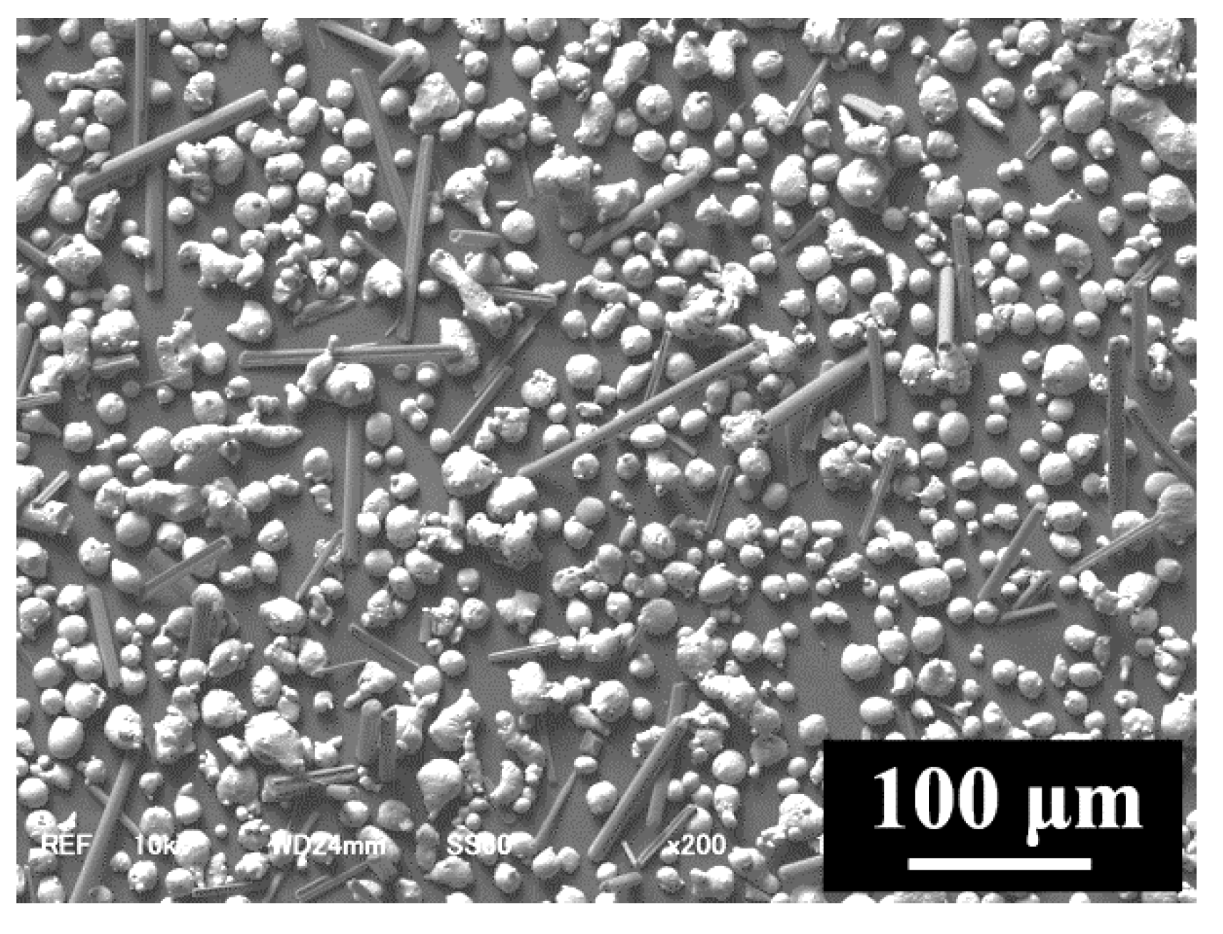
The test material was a mixed powder of pure aluminum powder and 10 mass% short carbon fiber (C/Al mixed powder). The gas atomized pure aluminum powder with a mean particle diameter of 21.7 μm was provided by Toyo Aluminium K.K., Osaka, Japan. The short carbon fiber (thermal conductivity: approximately 900 W/m·K), provided by Nippon carbon Co., Ltd., Tokyo, Japan, had a diameter of 5~10 μm and mean length of approximately 100 μm. The carbon fiber plated with copper was prepared using an electroless copper plating method by Teikoku-ion Co., Ltd., Osaka, Japan. The test powders were mixed via ball milling with a rotation speed of 105 rpm for 5 h. The rotation speed was determined from the critical rotation speed for the co-rotation of the mixed powder and alumina balls. Figure 2 shows a scanning electron microscope (SEM; JSM-6610, JEOL, Osaka, Japan) image of the C/Al mixed powder. The powder particles and carbon fibers were uniformly distributed to ensure that the mixed powder was suitable for preparing composites by SLM. To evaluate the laser reflectivity of powders, the light reflectivity was measured using a spectrophotometer V-700 (JASCO Corporation, Tokyo, Japan) at a wavelength of 200~2500 nm.
To determine the optimal laser scan conditions for the mixed powders, cubic SLM samples (10 × 10 × h15 mm) were prepared by varying the laser power and scan speed within the range shown in Table 1. The layer thickness and scan interval were fixed at 0.03 mm and 0.1 mm, respectively. The cubic SLM samples were therefore consisted of 500 layers. The relative densities of the samples were then measured via thresholding analysis of cross-sectional optical microscope (OM; MA100L, Nikon, Tokyo, Japan) images using the image analysis software IMAGE J Ver. 1.51 (National Institutes of Health, Bethesda, MD, USA). The average relative density was calculated from the values of five OM images of the vertical cross-section of each sample.
Vertical cross-sections of the samples were mirror-finished by polishing, and the microstructures were observed using the OM and SEM. Phase identification was carried out using an X-ray diffractometer (XRD; Smart Lab, Rigaku, Tokyo, Japan) with Cu Kα radiation, which operated at 40 kV and 150 mA.
Vickers hardness tests were performed on a vertical cross-section of each sample using a hardness tester HD-220D (Mitutoyo, Kanagawa, Japan) with an indentation load of 100 gf. Measured positions of the hardness tests were selected randomly on the cross-section. Thermal conductivity was evaluated by a laser flash method with a thermophysical property measuring instrument TC-7000H/SB-2 (ULVAC RIKO, Kanagawa, Japan). Disk-shaped samples with a diameter of 10 mm and a thickness of 3.5 mm were prepared in both parallel (0°) and perpendicular (90°) directions to the stacking direction, which means the direction that the thickness of samples increase during SLM process. Both surfaces of these disks were polished to a thickness of approximately 3.0 mm for measuring thermal conductivity.

3. Results and Discussion

3.1. Densification of C/Al SLM Composite

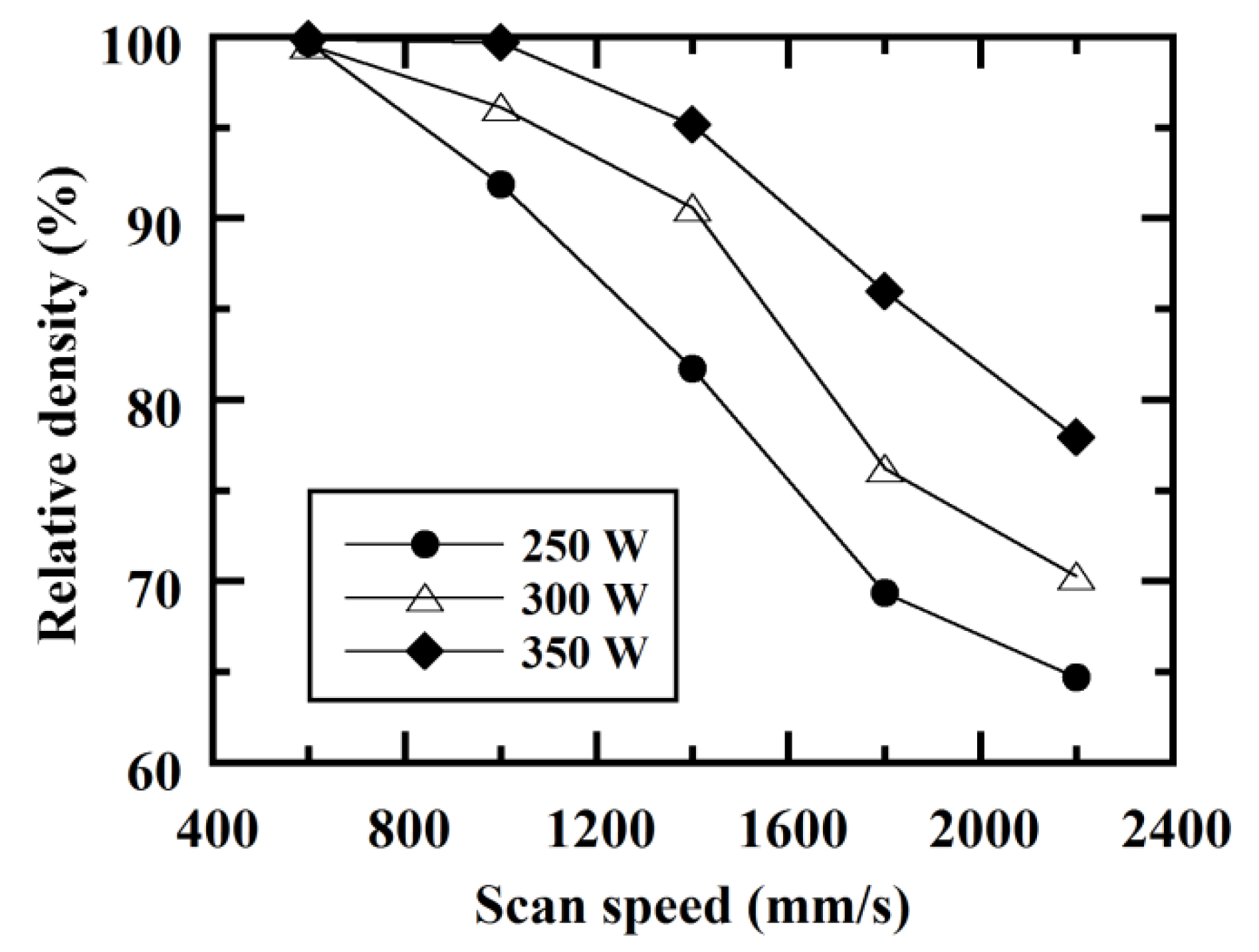
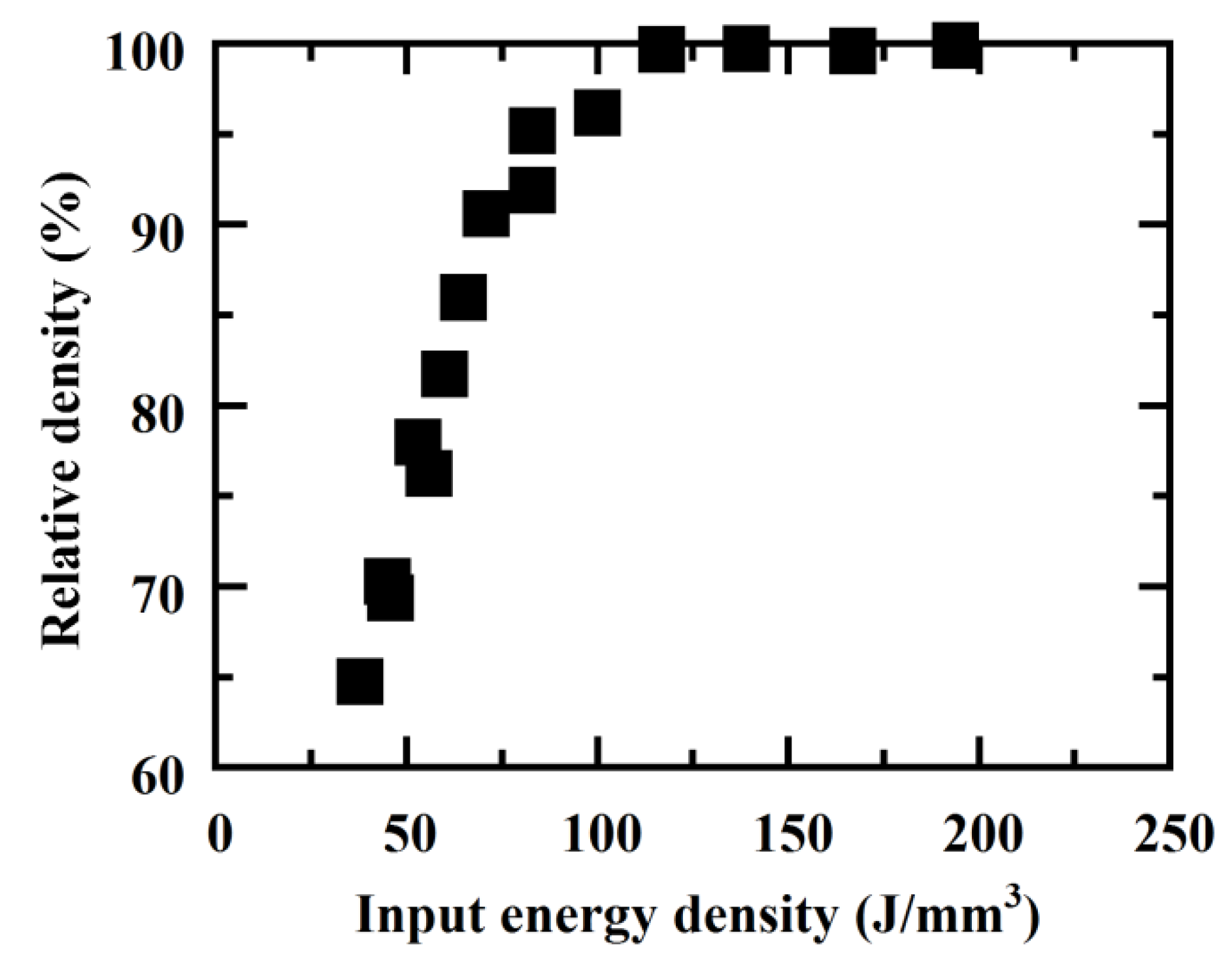
To investigate the processability of C/Al mixed powder, C/Al SLM composites were prepared by changing the laser scan conditions. Figure 3 shows OM images of vertical cross-sections of the C/Al composites. The black sections seen in the images indicate voids. The composites densify (i.e., the pores are removed) with increasing laser power and decreasing scan speed. Judging by the irregular shape of the pores, these were generated due to a lack of heat input. Figure 4 shows the relative density derived by thresholding analysis of cross-sectional OM images of the C/Al SLM composites. The relative density decreases as the laser power and scan speed become lower and higher respectively. To gain insight into the relationship between relative density and input energy density and powder layers by laser irradiation, the relative density values of the C/Al SLM composites prepared with changing laser scan conditions (Figure 4) were plotted as a function of the energy density. Figure 5 shows the result. The energy density Ed (J/mm3) is generally expressed as follows [14,34,35,36]:
Ed = P/(i·v·t)
where laser power is denoted by P (W), scan interval i, scan speed v (mm/s), and layer thickness t (mm). Interestingly, the relative density of C/Al SLM composites increases with increasing energy density, achieving the highest relative density of more than 99.5% under conditions with an energy density of greater than 100 J/mm3. This result suggests that appropriate control of the energy density by laser scan conditions can produce highly densified SLM composites. Kimura et al. [12,34] demonstrated that the energy density of the optimal laser scan conditions for densification in the pure aluminum and AlSi10Mg SLM specimens was 77.1 and 55.6 J/mm3 respectively. These values are significantly lower than that of the C/Al SLM composites in the present study. The irradiated laser for the C/Al mixed powder should be predominantly absorbed by carbon fiber since carbon generally has a high laser absorptivity. Therefore, more energy must be applied to melt the aluminum powder in the C/Al mixed powder. As a result, the high energy density was necessary for densifying the C/Al SLM composites.
From the above results, the optimal laser scan conditions for the C/Al SLM composite were selected (optimally processed material, laser power: 350 W; scan speed: 1000 mm/s), under which a relative density of more than 99.5% was obtained at the highest scan speed. As shown in Figure 3, dense C/Al SLM composite was achieved in the optimally processed material, although having a small number of tiny pores. The relative density of the optimally processed material was approximately 99.7%.

3.2. Characterization of C/Al SLM Composite

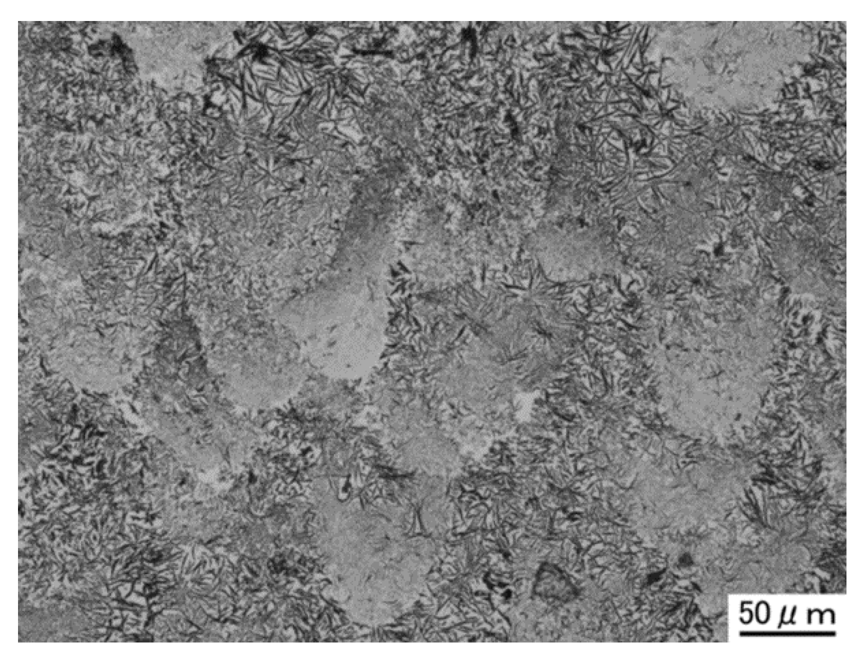
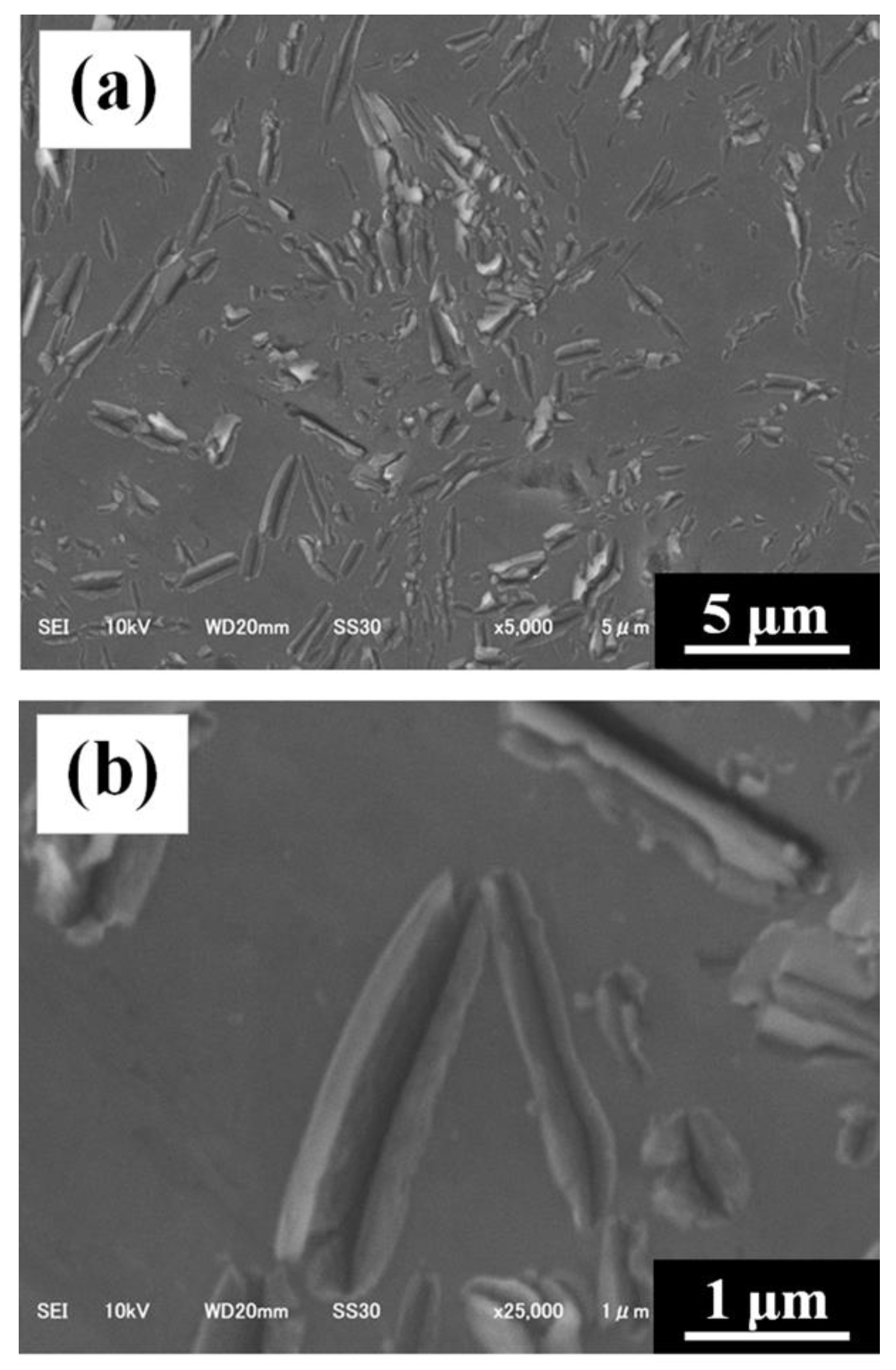
Figure 6 shows an enlarged OM image of the vertical cross-section of the optimally processed material with Rot scanning pattern. On a micron-scale, carbons are non-uniformly distributed at the beads (otherwise known as melt pool marks) formed during laser irradiation. Thin and short carbons are located at the lower tip portions, while thick and long carbons are located at the upper portion. Figure 7 shows SEM images of the vertical cross-section of the optimally processed material. Note that the size of all the carbons (diameter: less than 1 μm, length: less than 10 μm) is significantly smaller than that of initial carbon fibers (diameter: 5~10 μm, length: approximately 100 μm). Additionally, there are no cavities on the interfaces between the carbon and aluminum matrix (i.e., the wetting between carbon and aluminum could be ensured in the C/Al SLM composite), although the wettability between carbon and aluminum is generally poor.
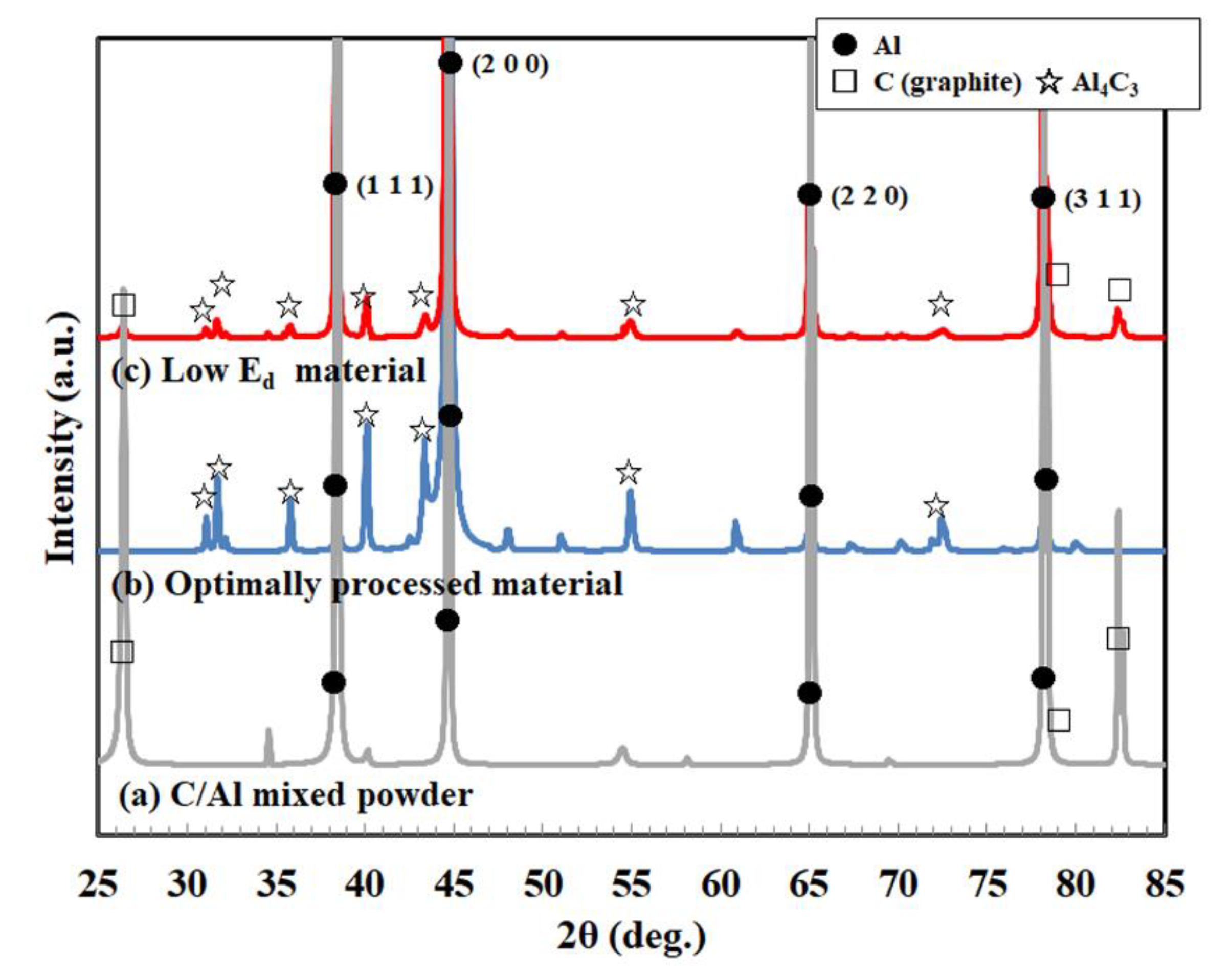
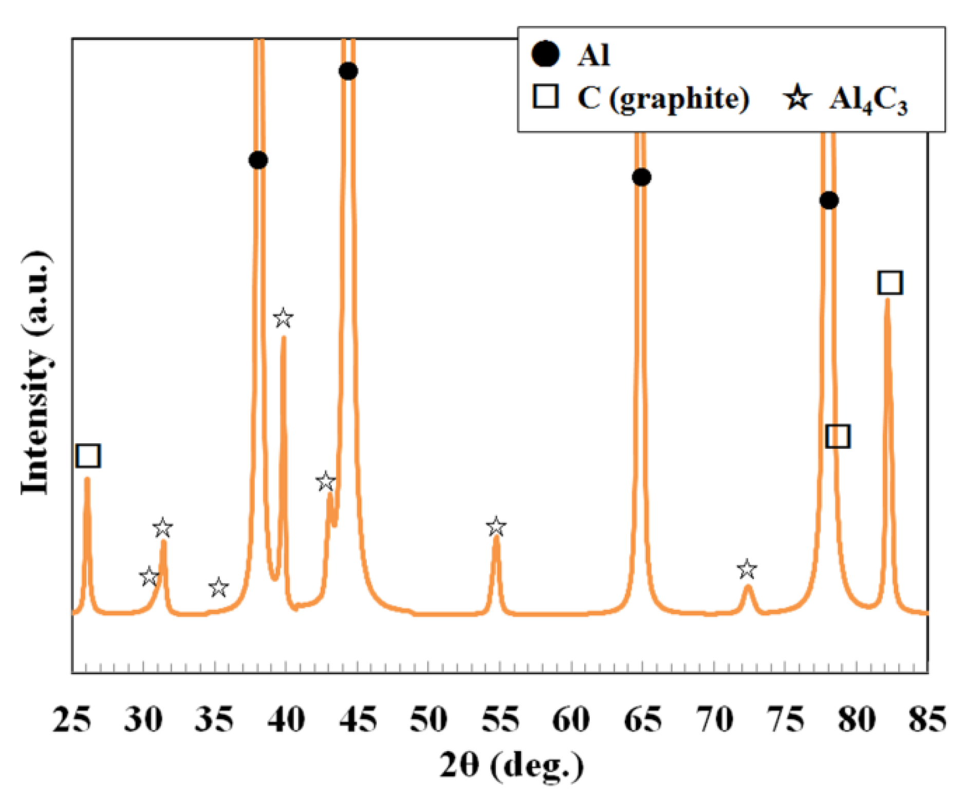
Here, we discuss the factor for the non-uniformed distribution and downsizing of carbons along with the improved wettability of a carbon and aluminum matrix. Figure 8 shows the results of phase identification by XRD in the C/Al mixed powder, optimally processed material and low energy density material (laser power: 250 W; scan speed: 1800 mm/s). Al and C (graphite) peaks are observed in the C/Al mixed powder. While in the optimally processed material, Al and Al4C3 peaks are observed instead of C peaks. Incidentally, the maximum temperature and solidification rate reached during the SLM process with aluminum alloy powders was estimated at more than 1700 °C [26] and 105–106 K/s [17,18] respectively. Since the C/Al mixed powder was used in the present study, it is considered that the absorption characteristics of the powder were different. Especially, the carbon should absorb the laser predominantly, leading to much higher temperature. Accordingly, the Al4C3 phase, which is the thermodynamically equilibrium phase [37], was generated due to the melting of carbon and/or thermal reaction between carbon and aluminum by the abundant heat generated during laser irradiation. Carbons were therefore downsized as mentioned above (Figure 7). In addition, it is known that the cooling rate in the beads of the Al SLM materials is varied by portions [18], namely the cooling rate of the lower tip portion of the beads is generally higher than that of the upper portion. Therefore, the non-uniformed carbon at the beads shown in Figure 6 likely originated from the difference in the cooling rate. Meanwhile, it is considered that the carbon was dissolved supersaturated in the α-Al matrix since solute elements including carbon are possibly dissolved in the matrix phase due to the high cooling rate during SLM process. On the other hand, weak C peaks partially remained in the low energy density material, suggesting that the inhibition of the Al-C reaction was due to low heat input. The good wetting between carbon and aluminum was due to the generation of Al4C3 phase on interfaces since the Al4C3 compound generally have improved wettability for aluminum [38]. Meanwhile, Nakae [39] has demonstrated that the wetting between carbon and aluminum improves with increasing temperature. Additionally, the maximum temperature and solidification rate during SLM processing should be high (respectively more than 1700 °C and 105–106 K/s, as mentioned above) in the C/Al SLM composite. Considering this aspect of the SLM process and the temperature dependency of wettability, the improved wetting between carbon and aluminum in the C/Al SLM composite was also attributed to that the thorough wettability at high temperature during laser melting could be kept until the solidified state owing to the extremely rapid melting-solidifying by laser irradiation.
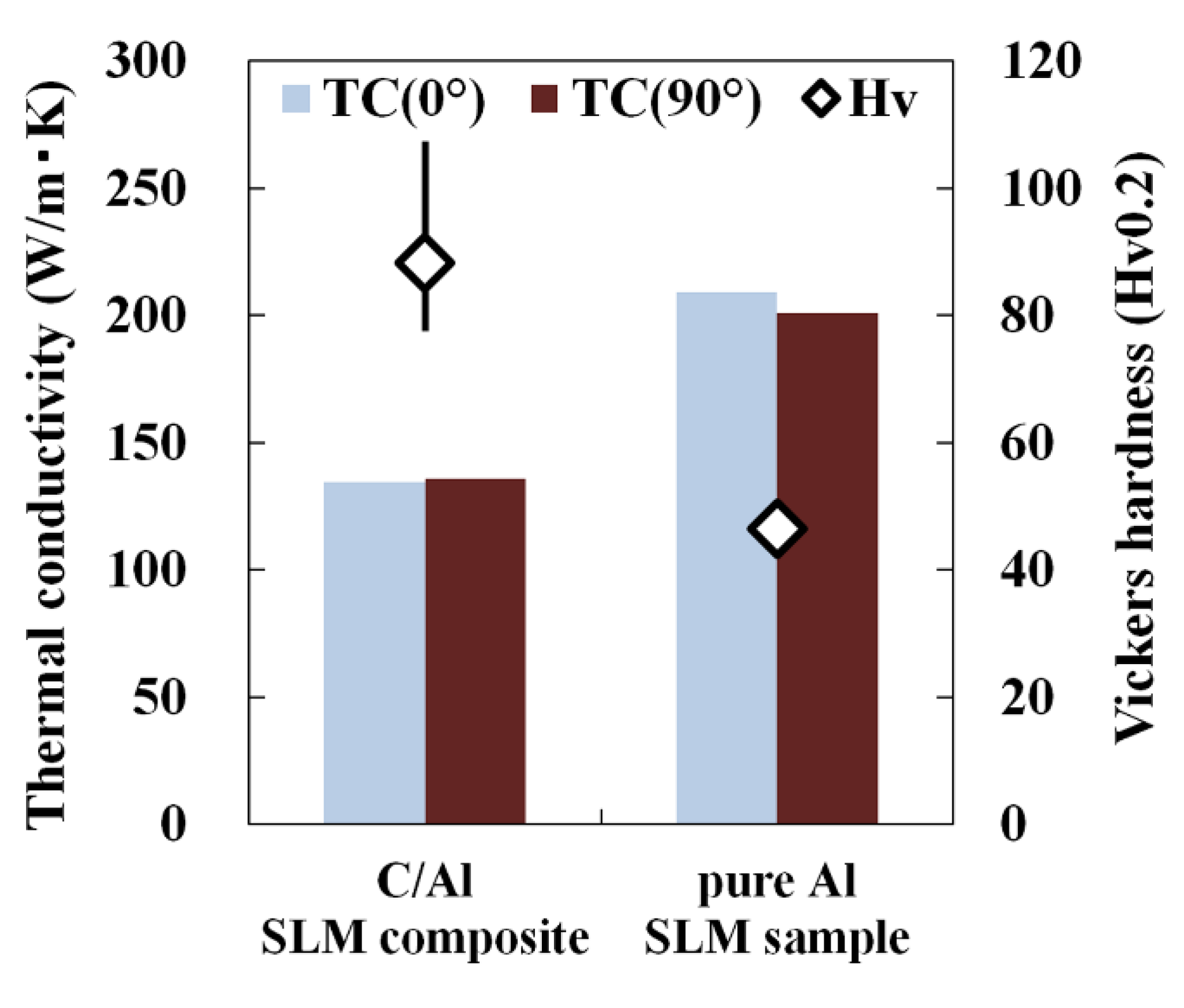
Figure 9 shows the Vickers hardness (shown in points) and thermal conductivity (shown in bars) of the optimally processed material (C/Al) together with pure aluminum (pAl) SLM sample. The pAl SLM sample was fabricated under the optimal laser scan conditions of laser power: 370 W, scan speed: 1600 mm/s, scan interval: 0.1 mm, and layer thickness: 0.03 mm [34]. The optimally processed material (90 Hv) shows significantly higher hardness compared with the pure aluminum SLM sample (45 Hv). Based on the microstructural observation results and above discussion, this is attributed to dispersion hardening (composite reinforcement) by the Al4C3 phase and solid-solution hardening by the supersaturated solid-solution carbon in the α-Al matrix via the Al-C reaction. On the other hand, the thermal conductivity of the optimally processed material (140 W/m·K) is approximately 30% lower than that of the pure aluminum SLM sample (200 W/m·K). The decrease in thermal conductivity was mainly attributed to increased solid-solution carbon in the α-Al matrix, leading to poor heat transfer characteristics in the C/Al SLM composite. Meanwhile, the difference in thermal conductivity between the 0° and 90° samples was not observed since the optimally processed material did not show anisotropy in its thermal conductivity.

3.3. Control of Laser Reflectivity by Copper Plating on Carbon Fiber

From the results in Section 3.1 and Section 3.2, the in-process preparation of the C/Al SLM composites has two major issues.
  • Reaction control between aluminum and carbon: the generation of Al4C3 phase and supersaturated solid-solution carbon in the α-Al matrix via the Al-C reaction led to difficulties in controlling the properties, specifically the thermal conductivity.
  • Control of the laser absorptivity of mixed powders for densification: since the carbon dominantly absorbed the laser, the aluminum powder could not gain the thorough input energy to melt, leading to difficult densification.
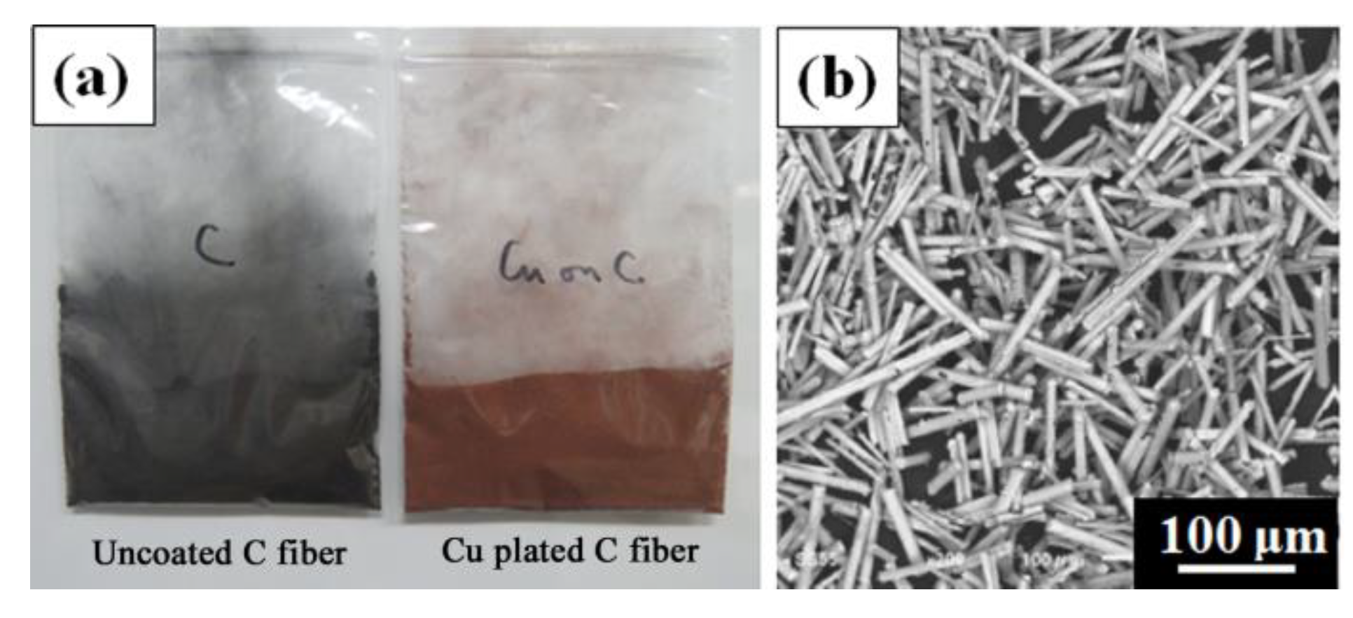
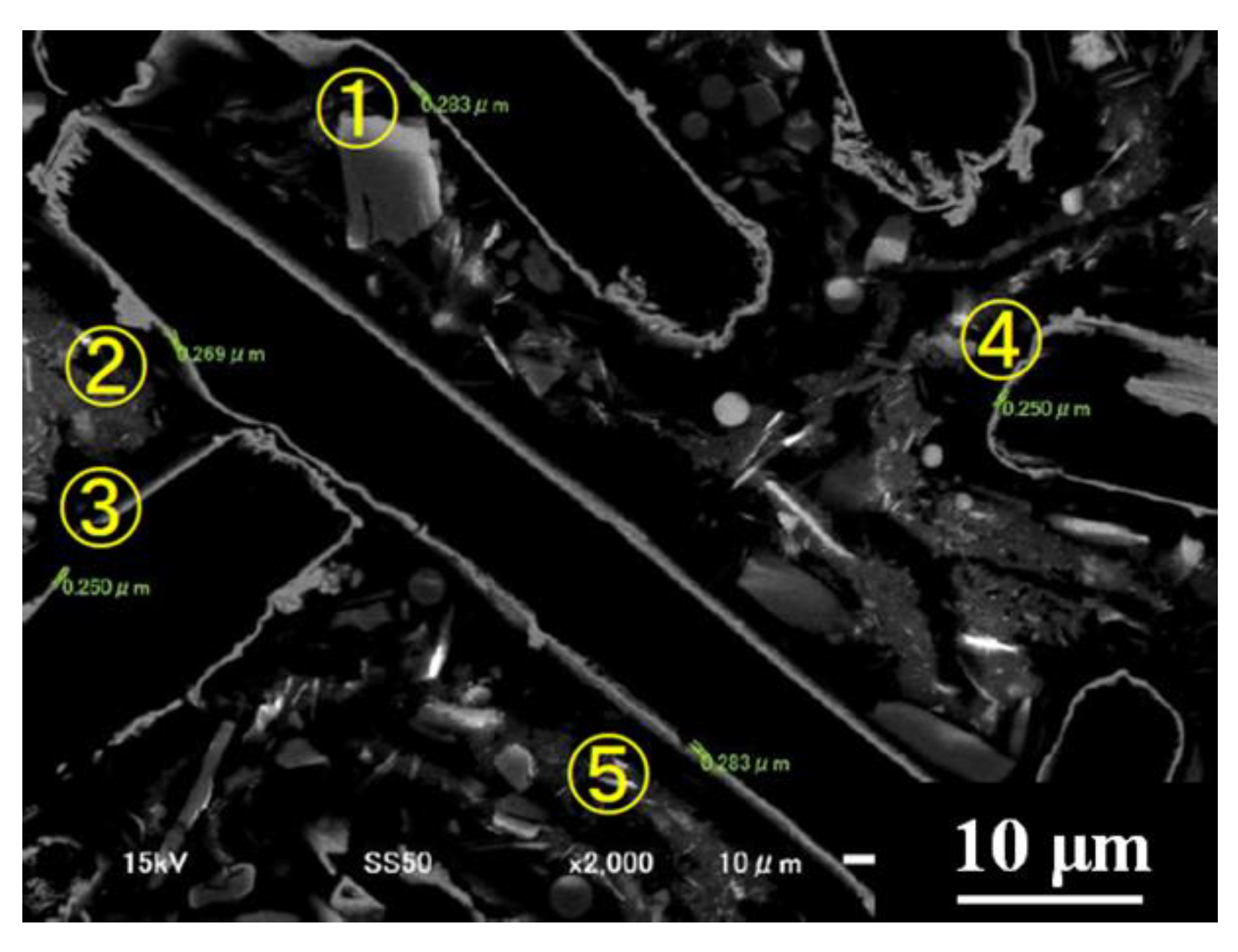
As a counterplan for the above issues, we propose the control of laser absorptivity by electroless copper plating on the carbon fiber. Copper generally has a high laser reflectivity [40], inhibiting the excessive laser absorption of the carbon fiber. Figure 10 shows an external photo and SEM image of carbon fiber plated with copper. The surface of the fibers is perfectly coated by the copper plate. Figure 11 and Table 2 show the cross-sectional SEM image of the copper-plated carbon fiber and the measurement results of the copper plate thickness respectively. The thickness is consistent across the sample, which is approximately 0.25 μm; this implies that the fibers are homogeneously covered with the copper plate.
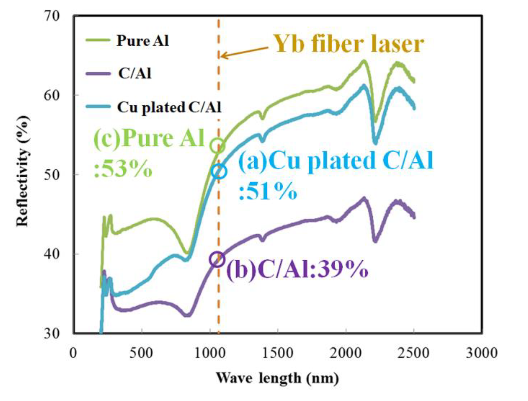
Another mixed powder for SLM (Cu plated C/Al mixed powder) was prepared by mixing the copper-plated short carbon fiber (10 mass%) and pure aluminum powder. Figure 12 shows the light reflectivity of the Cu plated C/Al mixed powder, C/Al mixed powder and pure Al powder measured using a spectrophotometer. The reflectivity of C/Al mixed powder (39%) at a wavelength of 1070 nm (corresponding to that of the Yb fiber laser used in the SLM machine) significantly decreases when compared to that of pure Al powder (53%). This is due to the high absorptivity of uncoated carbon fiber. Notably, the reflectivity of the Cu plated C/Al mixed powder (51%) increases to the level of pure Al powder. This suggests that the laser reflectivity (i.e., absorptivity) could be controlled by copper plating on the carbon fiber due to the high reflectivity of the copper plate.
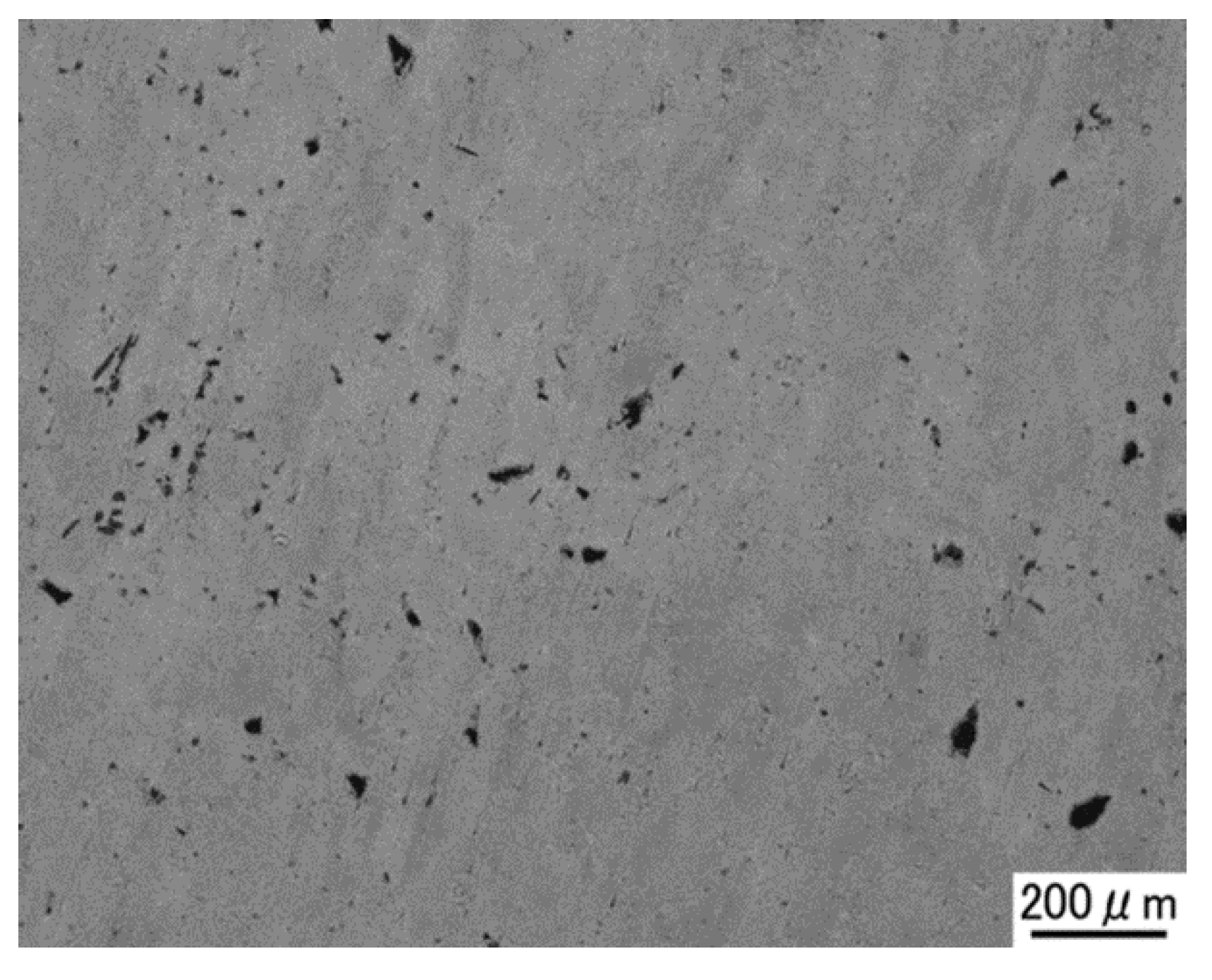
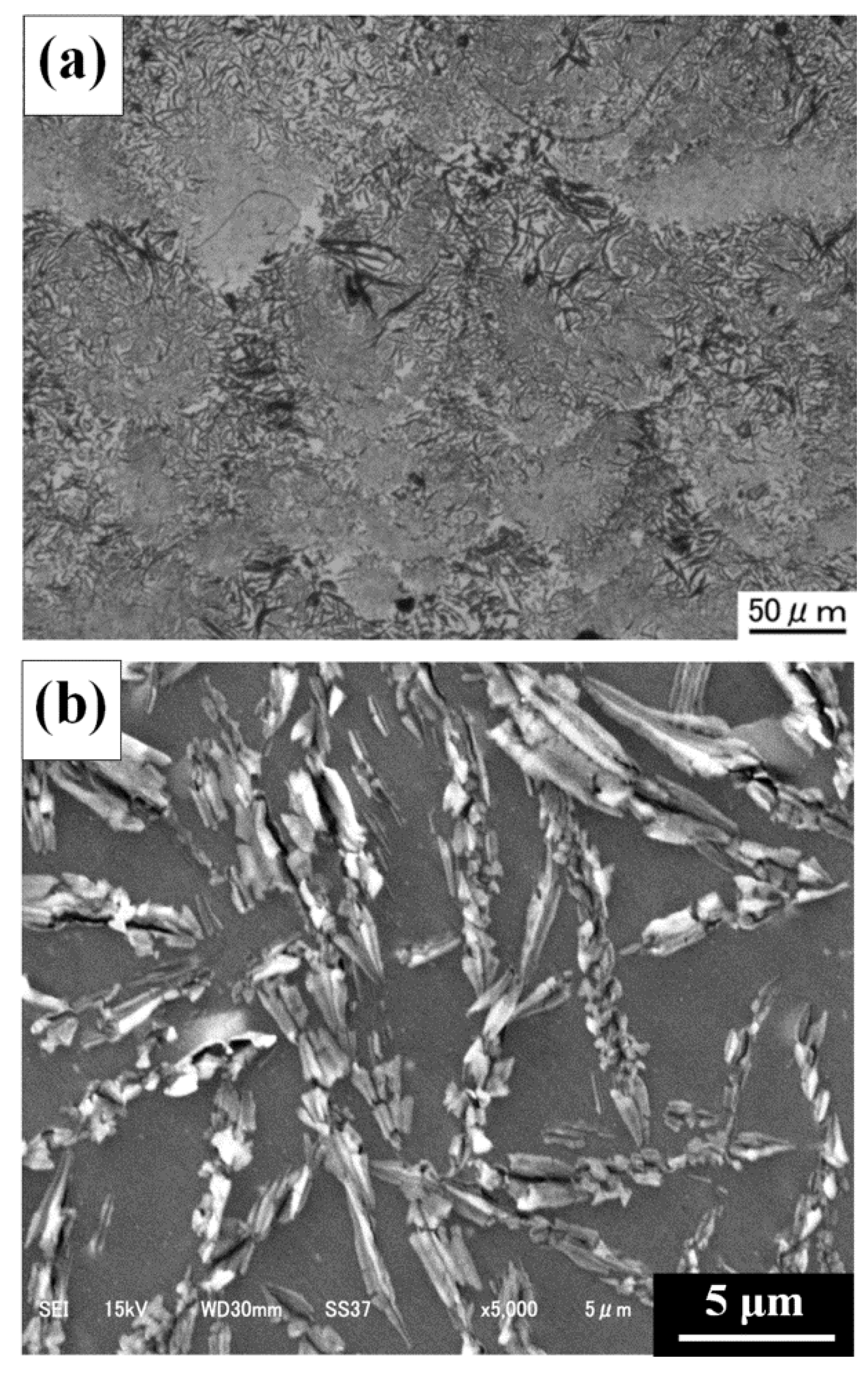
Figure 13 shows a cross-sectional OM image of a vertical plane of the SLM composite prepared with the Cu plated C/Al mixed powder (Cu plated C/Al SLM composite) at a laser power of 350 W and a scan speed of 1000 mm/s, which are the same as the optimal laser scan conditions of the C/Al SLM composite. The almost densified Cu plated C/Al SLM composite had a relative density of more than 99%. Figure 14 shows the enlarged (a) OM and (b) SEM images of a vertical plane of Cu plated C/Al SLM composite. An increased amount of carbon with larger size remains in the Cu plated C/Al SLM composite compared to the C/Al SLM composite in Figure 6 and Figure 7. Figure 15 shows the result of phase identification by XRD in the Cu plated C/Al SLM composite. Note that the C peaks together with Al and Al4C3 peaks are confirmed. The peaks of Cu and related compounds were not found because the amount of plated copper was small. The result indicates that the Al-C reaction could be inhibited in the Cu plated C/Al SLM composite due to the limited laser absorption of the copper-plated carbon fiber. Consequently, the densification and inhibition of the Al-C reaction in the Al SLM composite could be simultaneously achieved by controlling laser reflectivity via copper plating on carbon fiber in the mixed powder.
It is interesting to note that the plating on filler materials can provide an effective method for controlling the laser absorptivity of the powder materials (i.e., a process feature of SLM).
Figure 16 shows Vickers hardness and thermal conductivity of the Cu plated C/Al SLM composite and C/Al SLM composite. The hardness of Cu plated C/Al SLM composite is much higher than that of the C/Al SLM composite, although the thermal conductivity is unchanged. The strengthening can be attributed to additional solid-solution hardening by increased solid-solution copper in the α-Al matrix [41]. The unchanged thermal conductivity was due to increased solid-solution copper and residual copper plate on the carbon fiber. This led to the offset of any increase in thermal conductivity by residual carbon with a decrease in thermal resistivity by the solid-solution strain in the α-Al matrix and interfaces on the copper plate.

3.4. Generation of Anisotropy in Thermal Conductivity by Laser Scanning Pattern

In this section, the possibility to prepare a thermal management material from Al SLM composite, featuring anisotropic thermal conductivity, is investigated.
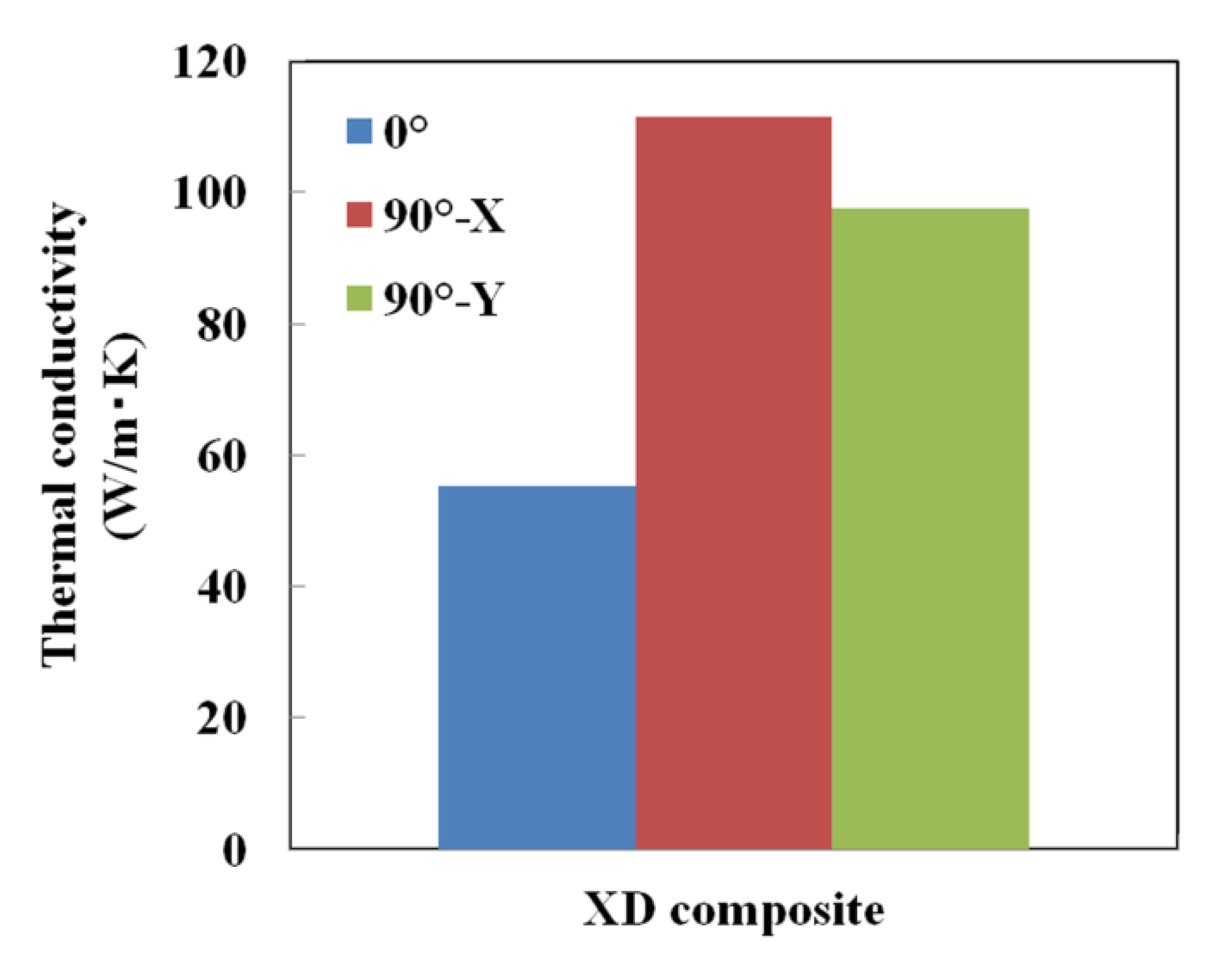
The Cu plated C/Al SLM composites were prepared with a unidirectional laser scanning pattern in the x-direction (XD), as shown in Figure 1. Figure 17 shows the thermal conductivity of the Cu plated C/Al SLM composite prepared with the XD scanning pattern (XD composite). The thermal conductivity of the 0° direction sample (the normal direction is parallel to the stacking direction) is twice as low as the 90° direction sample (the normal direction is perpendicular to the stacking direction). Notably, anisotropic thermal conductivity was observed in the XD composite in contrast to the Cu plated C/Al SLM composite prepared with a Rot pattern.
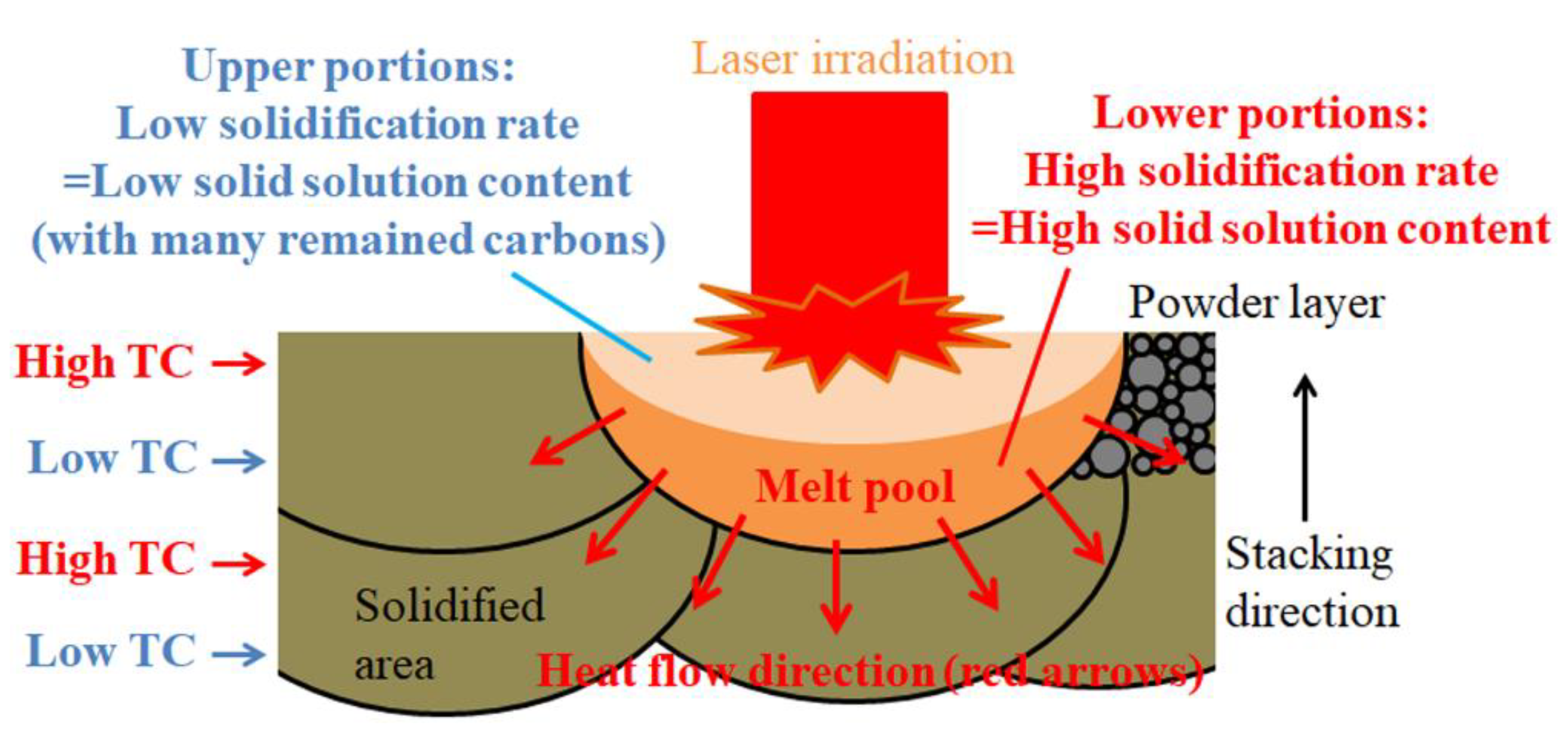
To gain insight into the observed anisotropic thermal conductivity, the cross-sections of the XD composite for each direction were observed by OM (Figure 18). Note that the beads distribute methodically in planes perpendicular to the stacking direction as a result of only scanning in the x-direction for each layer. As discussed in Section 3.2, the solid-solution content of carbon and copper in the lower tip portions of the beads is expected to be high due to the high solidification rate, leading to lower thermal conductivity. On the other hand, the upper portions also formed in layers could have relatively high thermal conductivity due to the low solid-solution content. Accordingly, the layers with high and low thermal conductivity were stacked alternately, as shown in the schematic illustration of Figure 19. The thermal conductivity in 0° direction sample was therefore low since the layer of aligned beads containing regions with low thermal conductivity (i.e., high thermal resistivity) acted as a barrier for free-electron conduction. Meanwhile, in the 90° direction sample, the upper portions of the beads with relatively high thermal conductivity have linked continuously in both the x- and y-directions, leading to the conservation of free-electron conduction. Consequently, the thermal conductivity of the 90° direction sample was higher than that of the 0° direction sample.

4. Conclusions

C/Al and Cu plated C/Al SLM composites were prepared in-process with mixed powders of pure aluminum and short carbon fiber. Based on the results discussed, the following conclusions could be reached.
(1)
C/Al SLM composites with a high relative density of 99.7% could be achieved by optimizing laser scan conditions with an energy density of greater than 100 J/mm3.
(2)
Vickers hardness of C/Al SLM composites was significantly higher than that of pure Al SLM material. The strengthening was attributed to the dispersion hardening by the generated Al4C3 phase and solid-solution hardening by solid-solution carbon in the α-Al matrix caused via the Al-C reaction. Meanwhile, the thermal conductivity of C/Al SLM composite decreased due to the increased content of solid-solution carbon.
(3)
Plating of copper on carbon fiber could control laser reflectivity in Cu plated C/Al mixed powder and prevent the Al-C reaction during SLM processing. As a result, the Vickers hardness of copper-plated C/Al SLM composites increased compared to that of the C/Al SLM composite, although the thermal conductivity remained unchanged.
(4)
A thermal management material possessing anisotropic thermal conductivity was obtained by applying a unidirectional laser scanning pattern in the SLM process for Cu plated C/Al mixed powder.
Consequently, the results show the possibility to prepare the carbon-dispersed aluminum MMCs in-process using SLM and the method for reaction control between matrix aluminum and carbon filler material. However, improved properties were limited to hardness in the present research. Future work includes the improvement of thermal conductivity and control of the anisotropy by increasing the amount of carbon fillers, along with the optimization of scan strategy and plating conditions on the fillers. These results can contribute to the further development of technology for SLM composites and the realization of thermal control parts and structural elements with improved functionality.

Author Contributions

Conceptualization, methodology, investigation, writing, T.K.; Conceptualization, writing—review and editing, T.N.; Methodology, T.S.; Data analysis, T.M. All authors have read and agreed to the published version of the manuscript.

Funding

This study was financially supported by “Research Grant for Aluminium” from Japan Aluminium Association.

Conflicts of Interest

The authors declare no conflict of interest.

References

  1. Gibson, I.; Rosen, D.W.; Stucker, B. Powder Bed Fusion Processes. In Additive Manufacturing Technologies; Springer: New York, NY, USA, 2010; pp. 103–142. [Google Scholar]
  2. Steen, W.M.; Mazumder, J. Rapid Prototyping and Low-volume Manufacture. In Laser Material Processing, 4th ed.; Springer: New York, NY, USA, 2010; pp. 349–369. [Google Scholar]
  3. Guo, N.; Leu, M.C. Additive manufacturing: Technology, applications and research needs. Frontiers Mech. Eng. 2013, 8, 215–243. [Google Scholar] [CrossRef]
  4. Milewski, J.O. Additive Manufacturing Metal, the Art of the Possible. In Additive Manufacturing of Metals; Springer: Cham, Switzerland, 2017; pp. 7–33. [Google Scholar]
  5. Yang, L.; Hsu, K.; Baughman, B.; Godfrey, D.; Medina, F.; Menon, M.; Wiener, S. Introduction to Additive Manufacturing. In Additive Manufacturing of Metals: The Technology, Materials, Design and Production; Springer: Cham, Switzerland, 2017; pp. 1–31. [Google Scholar]
  6. Yap, C.Y.; Chua, C.K.; Dong, Z.L.; Liu, Z.H.; Zhang, D.Q.; Loh, L.E.; Sing, S.L. Review of selective laser melting: Materials and applications. Appl. Phys. Rev. 2015, 2, 041101. [Google Scholar] [CrossRef]
  7. Matthew, W.; Tsopanos, S.; Chris, J.; Leuan, O. Selective Laser Melting of Heat Transfer Devices. Rapid Prototyp. J. 2007, 13, 291–297. [Google Scholar]
  8. Vilaro, T.; Abed, S.; Knapp, W. Direct Manufacturing of Technical Parts Using Selective Laser Melting: Example of Automotive Application. In Proceedings of the 12th European Forum Rapid Prototype, Paris, France, 5–6 March 2008. [Google Scholar]
  9. Kempen, K.; Thijs, L.; Humbeeck, J.V.; Kruth, J.P. Mechanical Properties of AlSi10Mg Produced by Selective Laser Melting. Phys. Procedia. 2012, 39, 439–446. [Google Scholar] [CrossRef] [Green Version]
  10. Manfredi, D.; Calignano, F.; Krishnan, M.; Canali, R.; Ambrosio, E.P.; Atzeni, E. From Powders to Dense Metal Parts. Characterization of a Commercial AlSi10Mg Alloy Processed through Direct Metal Laser Sintering. Materials 2013, 6, 856–869. [Google Scholar] [CrossRef] [Green Version]
  11. Buchbinder, D.; Meiners, W.; Wissenbach, K.; Lohmeier, K.M.; Brandl, E. Rapid Manufacturing von Aluminium-bauteilen fur die Serienproduktion durch Selective Laser Melting (SLM). In Proceedings of the Euro-uRapid, Frankfurt, Germany, 3–4 December 2007. [Google Scholar]
  12. Kimura, T.; Nakamoto, T. Microstructures and Mechanical Properties of Al-10%Si-0.4%Mg Fabricated by Selective Laser Melting. J. Jpn. Soc. Powder Powder Metall. 2014, 61, 531–537. [Google Scholar] [CrossRef] [Green Version]
  13. Aboulkhair, N.T.; Everitt, N.M.; Ashcroft, I.; Tuck, C. Reducing porosity in AlSi10Mg parts processed by selective laser melting. Addit. Manufact. 2014, 1–4, 77–86. [Google Scholar] [CrossRef]
  14. Kimura, T.; Nakamoto, T. Microstructures and Mechanical Properties of A356 (AlSi7Mg0.3) aluminum alloy fabricated by selective laser melting. Mater. Des. 2016, 89, 1294–1301. [Google Scholar] [CrossRef]
  15. Rao, H.; Giet, S.; Yang, K.; Wu, X.; Davies, C.H.J. The influence of processing conditions on aluminium alloy A357 manufactured by Selective Laser Melting. Mater. Des. 2016, 109, 334–346. [Google Scholar] [CrossRef]
  16. Prashanth, K.G.; Scudino, S.; Klauss, H.J.; Surreddi, K.B.; Lober, L.; Wang, Z.; Chaubey, A.K.; Kuhn, U.; Eckert, J. Microstructure and mechanical properties of Al-12Si produced by selective laser melting: Effect of heat treatment. Mater. Sci. Eng. A 2014, 590, 153–160. [Google Scholar] [CrossRef]
  17. Li, Y.; Gu, D. Parametric analysis of thermal behavior during selective laser melting additive manufacturing of aluminum alloy powder. Mater. Des. 2014, 63, 856–867. [Google Scholar] [CrossRef]
  18. Tang, M.; Pistorius, P.C.; Narra, S.; Beuth, J.L. Rapid Solidification: Selective Laser Melting of AlSi10Mg. JOM 2016, 68, 960–966. [Google Scholar] [CrossRef]
  19. Kimura, T.; Nakamoto, T.; Ozaki, T.; Sugita, K.; Mizuno, M.; Araki, H. Microstructural formation and characterization mechanisms of selective laser melted Al–Si–Mg alloys with increasing magnesium content. Mater. Sci. Eng. A 2019, 754, 786–798. [Google Scholar] [CrossRef]
  20. Zhang, J.; Song, B.; Wei, O.; Bourell, D.; Shi, Y. A review of selective laser melting of aluminum alloys: Processing, microstructure, property and developing trends. J. Mater. Sci. Technol. 2019, 35, 270–284. [Google Scholar] [CrossRef]
  21. Esawi, A.M.K.; Morsi, K.; Sayed, A.; Gawad, A.A.; Borah, P. Fabrication and properties of dispersed carbon nanotube–aluminum composites. Mater. Sci. Eng. A 2009, 508, 167–173. [Google Scholar] [CrossRef]
  22. Poirier, D.; Gauvin, R.; Drew, R.A.L. Structural characterization of a mechanically milled carbon nanotube/aluminum mixture. Compos. Part A 2009, 40, 1482–1489. [Google Scholar] [CrossRef]
  23. Luo, Z.P.; Song, Y.G.; Zhang, S.Q. A TEM study of the microstructure of SiCp/Al composite prepared by pressureless infiltration method. Scr. Mater. 2001, 45, 1183–1189. [Google Scholar] [CrossRef]
  24. Liu, H.N.; Ogi, K. Compressive failure of alumina continuous fibre reinforced Al–4.5 wt-%Cu alloy at elevated temperatures. Mater. Sci. Technol. 1999, 15, 821–825. [Google Scholar] [CrossRef]
  25. George, R.; Kashyap, K.T.; Rahul, R.; Yamdagni, S. Strengthening in carbon nanotube/aluminium (CNT/Al) composites. Scr. Mater. 2005, 53, 1159–1163. [Google Scholar] [CrossRef]
  26. Ogawa, F.; Masuda, C. Fabrication of VGCF reinforced aluminum matrix composites by powder can extrusion and investigation of their reinforcing mechanism. J. Jpn. Inst. Light Met. 2013, 63, 350–357. [Google Scholar] [CrossRef] [Green Version]
  27. Han, Q.; Setchi, R.; Lacan, F.; Gu, D.; Evans, S.L. Selective laser melting of advanced Al-Al2O3 nanocomposites: Simulation, microstructure and mechanical properties. Mater. Sci. Eng. A 2017, 698, 162–173. [Google Scholar] [CrossRef]
  28. Li, X.P.; Chen, Z.; Addad, A.; Wu, Y.; Wang, H.W.; Vleugels, J.; Humbeeck, J.V.; Kruth, J.P. Selective laser melting of nano-TiB2 decorated AlSi10Mg alloy with high fracture strength and ductility. Acta. Mater. 2017, 129, 183–193. [Google Scholar] [CrossRef]
  29. Wang, P.; Gammer, C.; Brenne, F.; Niendorf, T.; Eckert, J.; Scudino, S. A heat treatable TiB2/Al-3.5Cu-1.5Mg-1Si composite fabricated by selective laser melting: Microstructure, heat treatment and mechanical properties. Compos. Part B 2018, 147, 162–168. [Google Scholar] [CrossRef]
  30. Zhou, Y.; Duan, L.; Wen, S.; Wei, Q.; Shi, Y. Enhanced micro-hardness and wear resistance of Al-15Si/TiC fabricated by selective laser melting. Comp. Comm. 2018, 10, 64–67. [Google Scholar] [CrossRef]
  31. Liao, H.; Zhu, H.; Xue, G.; Zeng, X. Alumina loss mechanism of Al2O3-AlSi10Mg composites during selective laser melting. J. Alloys Compd. 2019, 785, 286–295. [Google Scholar] [CrossRef]
  32. Astfalck, L.C.; Kelly, G.K.; Li, X.; Sercombe, T.B. On the Breakdown of SiC during the Selective Laser Melting of Aluminum Matrix Composites. Adv. Eng. Mater. 2017, 19, 1600835. [Google Scholar] [CrossRef]
  33. Aversa, A.; Marchese, G.; Lorusso, M.; Calignano, F.; Biamino, S.; Ambrosio, E.P.; Manfredi, D.; Fino, P.; Lombardi, M.; Pavese, M. Microstructural and Mechanical Characterization of Aluminum Matrix Composites Produced by Laser Powder Bed Fusion. Adv. Eng. Mater. 2017, 19, 1700180. [Google Scholar] [CrossRef]
  34. Kimura, T.; Nakamoto, T. Thermal and Mechanical Properties of Commercial-Purity Aluminum Fabricated Using Selective Laser Melting. Mater. Trans. 2017, 58, 799–805. [Google Scholar] [CrossRef]
  35. Nakamoto, T.; Shirakawa, N.; Miyata, Y.; Sone, T.; Inui, H. Selective laser sintering of high carbon steel powders studied as a function of carbon content. J. Mater. Process. Technol. 2009, 209, 5653–5660. [Google Scholar] [CrossRef] [Green Version]
  36. Gu, H.; Gong, H.; Pal, D.; Rafi, K.; Starr, T.; Stucker, B. Influences of Energy Density on Porosity and Microstructure of Selective Laser Melted 17-4PH stainless Steel. In Proceedings of the Solid Freeform Fabrication Symposium, Austin, TX, USA, 12–14 August 2013; pp. 474–489. [Google Scholar]
  37. Mondolfo, L.F. PART 2—BINARY ALLOYS Aluminum-Carbon system. In Aluminum Alloys, 1st ed.; Butterworth-Heinemann: Oxford, UK, 1976; pp. 236–238. [Google Scholar]
  38. Kobashi, M.; Takata, N.; Suzuki, A. Reactive processing of aluminum matrix composites. J. Jpn. Inst. Light Met. 2017, 67, 571–575. [Google Scholar] [CrossRef]
  39. Nakae, H. Wettability of liquid aluminum to non-metallic materials. J. Jpn. Inst. Light Met. 1989, 39, 136–146. [Google Scholar] [CrossRef] [Green Version]
  40. Steen, W.M.; Mazumder, J. Basic Laser Optics—Reflection or Absorption. In Laser Material Processing, 4th ed.; Springer: New York, NY, USA, 2010; pp. 89–91. [Google Scholar]
  41. Mondolfo, L.F. PART 2—BINARY ALLOYS Al-Cu Aluminum-Copper system. In Aluminum Alloys, 1st ed.; Butterworth-Heinemann: Oxford, UK, 1976; pp. 253–278. [Google Scholar]
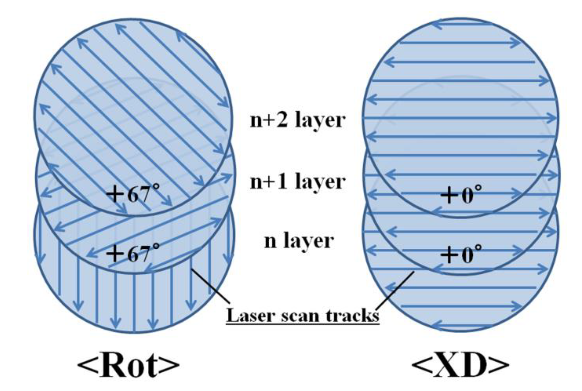
Figure 1. Schematic illustrations of laser scanning patterns. (a) rotation pattern (Rot), (b) unidirectional pattern of x-direction (XD).
Metals 10 00619 g001
Figure 2. Scanning electron microscope (SEM) image of C/Al mixed powder.
Metals 10 00619 g002
Figure 3. Optical microscope (OM) images of vertical cross sections of C/Al SLM composites with changing the laser scan conditions of laser power and scan speed.
Metals 10 00619 g003
Figure 4. Relative density of C/Al SLM composites as a function of laser scan conditions of laser power and scan speed.
Metals 10 00619 g004
Figure 5. Relative density of C/Al SLM composites as a function of energy density.
Metals 10 00619 g005
Figure 6. Enlarged OM image of a vertical cross section of the optimally processed material with Rot scanning pattern.
Metals 10 00619 g006
Figure 7. SEM images of vertical cross sections of the optimally processed material. (b) is enlarged image of (a).
Metals 10 00619 g007
Figure 8. XRD patterns of (a) C/Al mixed powder, (b) optimally processed material, and (c) low energy density material.
Metals 10 00619 g008
Figure 9. Vickers hardness (shown in points) and thermal conductivity (shown in bars) of the optimally processed material (C/Al SLM composite) and pure Al SLM sample.
Metals 10 00619 g009
Figure 10. (a) External photo and (b) SEM image of the carbon fiber plated with copper.
Metals 10 00619 g010
Figure 11. SEM image on a cross section of the carbon fiber plated with copper. (1–5: measurement points).
Metals 10 00619 g011
Figure 12. Light reflectivity of (a) Cu plated C/Al mixed powder, (b) C/Al mixed powder, and (c) pure aluminum powder, measured using a spectrophotometer.
Metals 10 00619 g012
Figure 13. OM image of a vertical cross section of the SLM composite fabricated with the Cu plated C/Al mixed powder under the laser scan conditions of 350 W laser power and 1000 mm/s scan speed.
Metals 10 00619 g013
Figure 14. Enlarged (a) OM and (b) SEM images of a vertical plane of the Cu plated C/Al SLM composite.
Metals 10 00619 g014
Figure 15. XRD pattern of Cu plated C/Al SLM composite.
Metals 10 00619 g015
Figure 16. Vickers hardness (shown in points) and thermal conductivity (shown in bars) of Cu plated C/Al SLM composite and C/Al SLM composite.
Metals 10 00619 g016
Figure 17. Thermal conductivity of Cu plated C/Al SLM composite fabricated with XD scanning pattern.
Metals 10 00619 g017
Figure 18. OM images of the (a) XY, (b) XZ, and (c) YZ cross sections of the Cu plated C/Al SLM composite fabricated with XD scanning pattern. Broken lines indicate solidification boundaries of beads.
Metals 10 00619 g018
Figure 19. Schematic illustration of beads formed by laser irradiation to powder bed.
Metals 10 00619 g019
Table 1. Laser scan conditions in the present study.
Laser Scan ConditionsSetting Range
Layer thickness (mm)0.03
Laser power (W)250–350
Scan speed (mm/s)600–2200
Scan interval (mm)0.1
Table 2. Measured thickness of the copper plate on carbon fibers.
Copper Plate Thickness (μm)
① 0.238
② 0.269
③ 0.250
④ 0.250
⑤ 0.283