Article

New Multistage Sheet-Bulk Metal Forming Process Using Oscillating Tools

1
Institut für Umformtechnik und Umformmaschinen (Forming Technology and Machines), Leibniz Universität Hannover, An der Universität 2, D-30823 Garbsen, Germany
2
Institut für Werkstoffkunde (Materials Science), Leibniz Universität Hannover, An der Universität 2, D-30823 Garbsen, Germany
*
Author to whom correspondence should be addressed.
Metals 2020, 10(5), 617; https://doi.org/10.3390/met10050617
Submission received: 9 April 2020 / Revised: 5 May 2020 / Accepted: 7 May 2020 / Published: 9 May 2020

Abstract

:
A new sheet-bulk metal forming process for the production of bulk components out of a flat sheet has been developed. Superimposed oscillation has been applied to the new process. By this means, process limits regarding better mould filling were expanded, and forming forces could be reduced. In order to investigate the effects of superimposed oscillation on material behaviour, plane strain and ring compression tests were carried out. The superimposed oscillated plane strain compression test showed a reduction in biaxial flow stress and thus in plastic work. Furthermore, reduced friction and roughness were verified in ring compression tests using superimposed oscillation.

1. Introduction

Nowadays, resource efficiency in the form of strict emission standards, lightweight design, and simultaneous cost reduction is very important in metal forming. In order to achieve resource-saving and sustainable production, new manufacturing methods have to be developed. The new technology of sheet-bulk metal forming (SBMF) combines both conventional sheet and bulk metal forming, applying bulk forming techniques to sheet metal. Thus, the SBMF technology enables the production of symmetric and asymmetric solid metal parts out of a flat sheet with functional components. Therefore, this new technology has enormous potential to shorten the process chain and reduce manufacturing costs. Merklein et al. defined SBMF as a technology to form flat sheets with a thickness from 1 mm to 5 mm with intended three-dimensional material flow as in bulk metal forming [1]. SBMF processes can be classified as well-known processes that are newly combined. These processes are characterised by a complex interaction between forming zones of high and low strains, as well as by locally varying two and three-dimensional states of stresses and strains.
The main topic of this paper is the development and analysis of a new multistage SBMF process for the first-time production of components with internal and external gearing out of a flat sheet in three process stages. SBMF processes show specific limits, especially with regard to insufficient mould filling and high forming forces. These problems are addressed in this research. Therefore, the influence of superimposed oscillation on forming behaviour is investigated exemplarily in a multistage process. First investigations on the influence of superimposed oscillation on metal forming processes were carried out by Garskii and Efromov [2]. Olsen et al. investigated the influence of superimposed oscillation on wire drawing in bulk metal forming [3]. In sheet metal forming, numerous studies on superimposed oscillating deep drawing processes exist. One of the few methods that were implemented industrially is the superimposed oscillated deep drawing process investigated by Siegert and Ziegler [4]. The advantages of superimposed oscillation are reduced power consumption (in the range of 40% for ultrasonic frequencies [5]), corresponding workload reduction, as well as a shorter process chain due to higher degrees of surface quality [6], rendering post-processing steps obsolete. The influence of superimposed oscillation in the ultrasonic range on metal forming processes can be assessed in two effects. First, the volume effect identified by Blaha and Langenecker describes decreasing flow stress as a result of the activation of anchored dislocations caused by ultrasonic oscillation [5]. Second, the surface effect investigated by Siegert and Ulmer explains a decrease in the effective coefficient of friction by a periodic reduction of the contact surfaces between the workpiece and tool [6]. In comparison to magnetostrictively or piezoelectrically generated ultrasonic oscillation, the superimposed oscillation used in the new SBMF process is generated by an innovative hydraulic system. By means of the design of this hydraulic system consisting of a rotary piston valve and a high-frequency cylinder, high excitation amplitudes can be realised at a high excitation frequency.
The integration of this oscillation in the SBMF process to overcome forming limits is a subject of this study. To investigate the effects of this oscillation, basic investigations such as flat and ring compression tests are conducted. All experiments are carried out with the same oscillation parameters (of f = 200 Hz and A = 20 µm) in order to achieve a comparability of the occurring effects.

2. Material Characterisation and Friction Testing in SBMF

According to Tekkaya, the simulation-based process design of the new forming process requires material characterisation [7]. The uniaxial tensile test allows ascertaining the frictionless true stress–true strain curve only within uniform elongation. To generate a flow curve with high strain values for SBMF processes, the true stress–strain curve from uniaxial tensile stress is usually extrapolated beyond the instability point by different mathematical approaches. Becker et al. showed that a more accurate extrapolation could be achieved in a plane strain compression test allowing for an experimental determination of true stress–true strain curves at higher strain values [8].
Apart from material behaviour, also tribological conditions have a significant influence on product quality and tool service life in metal forming. According to Avitzur, ring compression tests are suited for a quantitative description of friction conditions due to a simple test preparation in combination with sufficient accuracy [9]. Furthermore, tribological effects such as the coefficient of friction and friction factor have a significant influence on finite element (FE) simulation and thus on process and tool design. Löffler et al. analysed and verified the fundamental suitability of ring compression tests for SBMF technology [10].

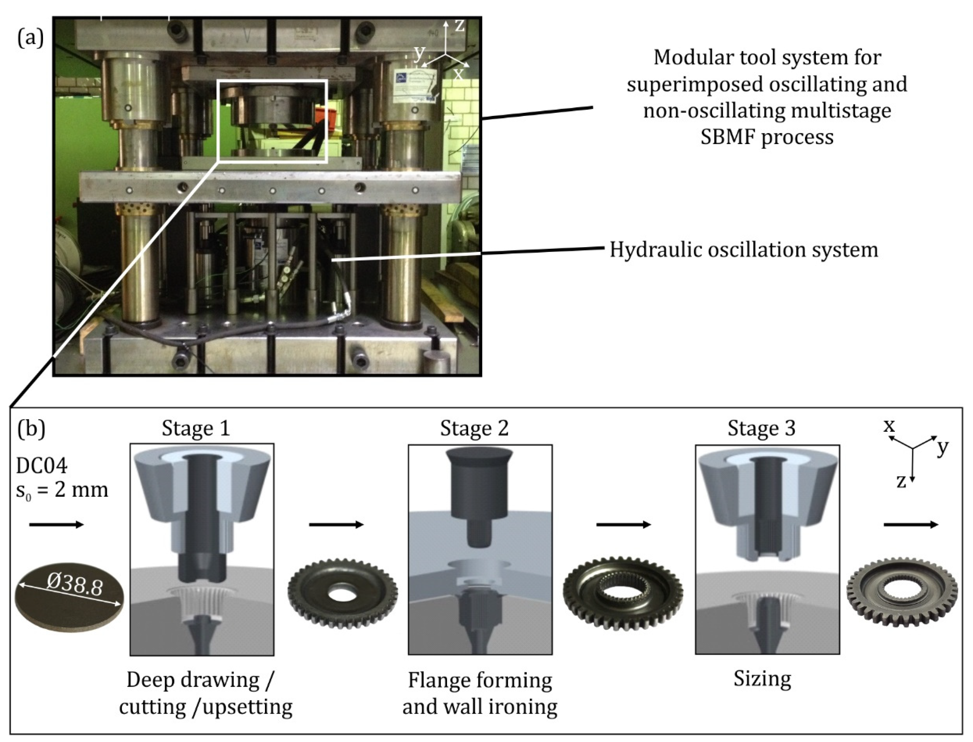
3. Multistage SBMF Process

By means of the newly developed multistage SBMF process, a complex functional symmetrical component with internal and external gearing can be produced out of a flat sheet. The whole process chain, shown in Figure 1, consists of three stages with six manufacturing processes. The first stage combines deep drawing without blank holder, cutting and upsetting. The result of the first stage is a semi-finished symmetrical part with external gearing and a hole in the middle of the component. The external gearing has a targeted geometry of a tooth height of 2.1 mm, a module of one, and a teeth number of 38. This geometry is entirely achieved in the first process stage.
In the next process stage, flange forming and wall ironing are conducted simultaneously to form the internal gears. Due to incomplete mould filling of the internal gearing in the second stage, it is sized in the third stage. In order to reduce the process development time, FE simulations of single stages were conducted and analysed by Behrens et al. [11].
Numerical and experimental investigations have been carried out using a mild steel DC04 (1.0338) with 2 mm sheet thickness. A blank sheet of 38.8 mm in diameter was used as a semi-finished sheet plate. The numerical investigation was conducted as a 3D model setup in simufact.forming v.14 (Simufact Engineering GmbH, Hamburg, Germany). To reduce the calculation time, all the tools were modelled as discrete rigid bodies. Linear tetrahedral elements with an edge length of 0.5 mm were used. For detailed modelling of the gearing, refinement areas were discretised with an edge length of 0.125 mm. Furthermore, an anisotropic material behaviour was also taken into account in the numerical setup. Contact conditions between tools and part were modelled using the combined friction law with the coefficient of friction µ = 0.1 and a friction factor m = 0.15. Material properties of the steel were determined by means of the tensile test according to DIN EN ISO 6892 and the hydraulic bulge test according to ISO 16808 [12].
Figure 2 depicts numerical and experimental process forces of the individual stages. The comparison shows a good agreement between simulation and experiments. The differences in force curves can be attributed to process influences such as gas spring forces, tool stiffness, as well as varying sheet thickness. The press speed is kept constant at 10 mm/s for every process stage.
In addition to process forces, mould filling of the tooth cavity is one of the most important process characteristics decisive for part quality. The experimental results of mould filling in the first stage analysed by Matthias et al. showed a complete forming of the external gearing [13].
Mould filling of the experimentally formed gears was determined with the measuring microscope VR3200 by the company Keyence (Osaka, Japan). The proportion of numerical mould filling was determined by a measurement in material flow simulation. In comparison, mould filling of the tooth cavity reached about 36% after the second stage in the experiment. FE simulations depict similar results according to Figure 3.
Mould filling in the second stage primarily depends on the die clearance u. Based on the sheet thickness of 2 mm, an optimal die clearance of 1.25 mm was calculated. The reduction in die clearance leads to increasing burr formation on the upper side of the teeth and was thus not investigated at this point.
The aim of the last stage is sizing of the internal gearing. In order to evaluate the numerical results, the maximum experimental force FP = 200 kN was chosen in this stage. Compared to the FE simulation, a mould filling of 90% was achieved in experimental investigations. The differences should be attributed to the effects of rigid bodies in the finite element (FE) modelling of the tools. Both numerical and experimental mould filling results are illustrated in Figure 4. One possibility to overcome the process limits of the second and third forming stages is the integration of superimposed oscillation in the new SBMF process.

4. Basic Investigations on Superimposed Oscillation in SBMF

Before integrating oscillation into the new process, fundamental investigations have been carried out in order to analyse the influence of oscillation on material and tribological behaviour.

4.1. Plane Strain Compression Test

The plane strain compression test is used to determine biaxial true stress–true strain curves due to a homogenous material flow up to high strain values. Thus, the influence of superimposed oscillation on the forming behaviour can be described. To introduce superimposed oscillation in a plane strain compression test, a new tool system has been developed (Figure 5). This tool system consists of two main components: a plane strain compression tool and a hydraulic oscillation unit. The hydraulic oscillation unit developed by Behrens et al. is able to realise an excitation frequency spectrum between 0 and 600 Hz at excitation amplitudes of 10–50 µm [14]. The displacement stroke of the sheet specimen can be measured by a laser-displacement sensor. The detection of forming force absorption during the experiment is realised by a load cell placed between the plane strain compression tool and hydraulic oscillation system.
At the beginning of the experiment, the sheet specimen is positioned between the dies. Then, the upper die moves from the top to the bottom. Shortly before the upper die starts to form the specimen, the hydraulic oscillation system and thus the tool subassembly including the lower die starts to oscillate. During superimposed oscillation, the upper die compresses the sheet specimen up to the desired specimen height, which is guaranteed by limit stops.
The sheet specimens are cut out of a 2 mm thick mild steel DC04 by water jet cutting. Figure 5b depicts a specimen before and after the plane strain compression test. The upper and lower dies are made of high-speed steel (1.3343). The oscillating and non-oscillating experiments are carried out at room temperature, and the upset speed is kept constant at 1 mm/s. All tests are carried out with a frequency of 200 Hz and an amplitude of 20 µm without lubricant to keep the boundary conditions constant.
In order to investigate the influence of superimposed oscillation on the material behaviour, the biaxial true stress (Equation (1)) and true strain (Equation (2)) values are calculated based on the experimental force and stroke values according to the equations derived by Rietmann [15]:
σ bia = σ V ,   vM = F a b 2   3 4 t + m a
ε V , vM true = 3 2 l n t t 0
Here, F is the experimental compression force and m is the friction factor between the punch and sheet specimen. The geometrical parameters can be taken from Figure 5b. Since the experimental force F already includes the friction term, the friction factor has been eliminated from Equation (1). Figure 6 depicts the biaxial true stress–true strain curves of oscillating and non-oscillating plane strain compression tests. According to Figure 6, the maximum biaxial flow stress of the superimposed oscillating and non-oscillating processes is identical. The biaxial flow stress is reduced by up to 21.8% under superimposed oscillation. The dashed line in Figure 6 right represents the average flow stress of all experiments carried out under superimposed oscillation.
The plastic forming work can be calculated as the area under the force curve in a force–stroke diagram. In order to determine the plastic forming work Wt of the plane strain compression test, the area under the experimental force profile should be calculated by determining the integral of Equation (3).
W t = 0 s F t ( s ) d s
Taking the experimental force profile F and the end of the forming stroke s, the plastic work of the plane strain compression test is 28 J. The comparison of the plane strain compression tests shows that superimposed oscillation with an excitation frequency of 200 Hz and an excitation amplitude of 20 µm reduces the total plastic work by up to 14% according to Figure 7.

4.2. Tensile Test

In order to investigate the influence of superimposed oscillation, the microstructure of the material was characterised under a Transmission electron microscopy (TEM) microscope after a tensile test. Tensile tests allow for an investigation without the influence of friction and have been carried out with and without superimposed oscillation. For microstructure analysis, the specimens were cut out in the direction of tensile load by electrical discharge machining. Subsequently, the TEM foils were prepared by mechanical grinding and electrolytic thinning.
Figure 8 shows the comparison of micrographs for the specimens tested without oscillation (Figure 8a) and loaded with superimposed oscillation (Figure 8b). As a result of plastic deformation, there is a reorientation of the dislocation networks within a grain. The arrangement of these networks is influenced by the superimposed oscillation. Under uniaxial load, regularly distributed dislocation accumulations are shaped similar to dislocation cells (Figure 8 dashed lines).
These dislocation networks are less strongly pronounced under superimposed oscillation; respectively, the cell walls are more diffuse, as shown in the detailed view (Figure 8b arrows). Superimposed oscillation appears to lead to smaller dislocation cells, a smaller dislocation density at the cell walls, and an increase in dislocations in the cell centre; see Figure 8.

4.3. Ring Compression Test

Compared to plane strain compression tests, ring compression tests allow for large relative contact area changes between the specimen and tool due to the forward material flow and across the upsetting direction. Therefore, in order to analyse the presumed friction effects on superimposed oscillating processes more precisely, oscillating and non-oscillating ring compression tests are carried out. Furthermore, the influence of superimposed oscillation on the surface roughness of ring specimens is analysed. The experimental test stand for the ring compression tests is shown in Figure 9. Analogous to the tool system of the plane strain compression tests, it is installed above the hydraulic oscillating device. The tactile measuring device T8000-RC by the company Hommel (ETAMIC GmbH, Jena, Germany) is used to measure the surface roughness of the ring compression test specimen.
For the implementation of superimposed ring compression tests, the tool system for plane strain compression tests is adjusted by Koch et al. [16]. The ring specimens were cut out of a 2 mm thick mild DC04 sheet blank by water jet cutting and have a ratio of 6:3:2 between the external diameter, internal diameter, and height. The superimposed oscillating ring compression tests are carried out with an excitation frequency of 200 Hz and an excitation amplitude of 20 µm. To investigate the friction conditions between ring specimen and tools, the inner diameter of the ring specimen is measured after the ring compression tests. By means of this method, the friction coefficient can be determined, which increases with decreasing inner diameter. The analysis of the specimens shows that after superimposed oscillating tests, the inner diameter of the ring specimens is smaller than after non-oscillating ring tests. Based on the results, it can be stated that superimposed oscillation reduces the friction between specimen and tool. The friction factor m was calculated according to Avitzur and Cockcroft and showed a reduction from 0.34 to 0.29 under superimposed oscillation [9]. This effect could be due to the permanent interruption of surface contact between the tools and ring specimen and the reduced surface roughness caused by superimposed oscillation. The roughness investigations of the upper and lower surface of the ring specimens show that the arithmetic mean roughness Ra of the specimen surface is lower when using superimposed oscillation. This smoothing effect is observed by Koch et al. for all compressed ring specimens, regardless of their respective compression height [16]. The results of the arithmetic mean roughness Ra of the ring specimens as well as their inner diameter are summarised in Figure 10 and show the interaction of both aforementioned effects.

5. Superimposed Oscillation in the Multistage SBMF Process

Basic investigations on superimposed oscillation show a positive influence on the reduction of plastic work and friction conditions. In order to evaluate these effects, the hydraulic oscillation system is integrated in the new multistage SBMF process. Figure 1a depicts the modular tool system for the oscillation-superimposed multistage SBMF process. The oscillations are generated in the bottom active tool elements such as deep drawing, flange forming, as well as upsetting punch. Design challenges of the new modular tool system are close tolerances for the active tool elements combined with the introduction of superimposed oscillation in the force main flow of the tool. In order to prevent the punch fixed to the hydraulic oscillation system from changing its position, a special guide is designed for this tool element.
Consequently, an opportunity occurred to investigate the influence of superimposed oscillating on mould filling. Oscillations with an excitation amplitude of 20 µm and an excitation frequency of 200 Hz were introduced in the second forming stage under the same boundary conditions. The press speed is 10 mm/s for superimposed oscillated and oscillation-free experiments. As a result, mould filling of the tooth cavity has increased by up to 6%, as shown in Figure 11a. According to the force–stroke diagram in Figure 11b, the forming force is reduced by up to 14% during superimposed oscillating experiments compared to non-oscillating experiments. The reason for these effects should be the reduced friction caused by the permanent interruption of surface contact between tools and specimen. According to Figure 11b, optical inspection of the internal gearing shows that superimposed oscillation reduces burr formation on the upper side of the teeth.
During the second stage, mould filling of the internal gearing cannot be achieved. Subsequently, the internal gearing is sized. In the third forming stage, the oscillated and non-oscillated preformed internal gearing of the second forming stage is sized by superimposed oscillating and non-oscillating processes.
As a result, mould filling of the internal gearing of 95% is achieved by means of superimposed oscillation in the third forming stage. The same experimental test without superimposed oscillation achieves mould filling of the internal gearing of 90%.
Identical to the second forming stage, the force–stroke diagram of the sizing process in Figure 12b shows a lower forming force caused by superimposed oscillation. The forming force was reduced by up to 9% compared to the experiments without superimposed oscillation. The above-mentioned phenomenological effects of superimposed oscillation should be due to the reduction of friction between the forming tools and the specimen.

6. Conclusions

This study is focused on the development of a new SBMF process as well as on the expansion of its process limits by superimposed oscillation. First, process limits were identified and analysed by numerical and experimental investigations. Afterwards, the material behaviour of mild steel DC04 was investigated during superimposed oscillating and non-oscillating plane strain compression tests. The results showed a lower biaxial stress and thus lower plastic forming work under superimposed oscillation. Ring compression tests revealed that the superimposed oscillation causes lower friction while simultaneously decreasing the surface roughness of ring specimens compared to non-oscillating tests. After fundamental investigations, the introduction of oscillations in the SBMF process took place and caused better mould filling of the tooth cavity and a lower forming force. Thus, it could be shown that not only known ultrasonic oscillation but also the oscillation generated by the hydraulic system has a positive influence on metal forming.
Future investigations will focus on the influence of superimposed oscillation on material behaviour under varying frequencies and amplitudes. Furthermore, material microstructure evolution depending on superimposed oscillation will be investigated in more detail. Moreover, the combination of lubrication and superimposed oscillation will be analysed by ring compression tests.

Author Contributions

Conceptualisation, D.R.; Formal analysis, S.K. and D.R.; Investigation, P.M., H.-B.B., G.G., S.K. and D.R.; Methodology, B.-A.B.; Project administration, B.-A.B. and S.H.; Supervision, B.-A.B. and S.H.; Visualisation, S.K. and D.R.; Writing—original draft, D.R.; Writing—review and editing, B.-A.B. All authors have read and agreed to the published version of the manuscript.

Funding

Funded by the Deutsche Forschungsgemeinschaft (DFG, German Research Foundation): grant number 116817829; 247913894. The authors thank the German Research Foundation (DFG) within the scope of the subproject A7 (116817829) and C6 (247913894) of the Transregional Collaborative Research Center (TCRC 73).

Acknowledgments

The authors thank the German Research Foundation (DFG) within the scope of the subproject A7 (116817829) and C6 (247913894) of the Transregional Collaborative Research Center (TCRC 73)

Conflicts of Interest

The authors declare no conflict of interest.

References

  1. Merklein, M.; Allwood, J.M.; Behrens, B.-A.; Brosius, A.; Hagenah, H.; Kuzman, K.; Mori, K.; Tekkaya, A.E.; Weckenmann, A. Bulk forming of sheet metal. CIRP Ann. 2012, 61, 725–745. [Google Scholar] [CrossRef]
  2. Garskii, F.K.; Efromov, V.I. Effect of ultrasound on the decomposition of solid solutions. Izv. Akad. Nauk Beloroussk SSR 1953, 3. [Google Scholar]
  3. Olsen, K.M.; Jack, R.F.; Fuchs, E.O. Wire drawing in ultrasonically agitated lubricants. Wire Wire Prod. 1965, 40, 1566–1568. [Google Scholar]
  4. Siegert, K.; Ziegler, M. Pulsating blank holder force in the deep-draw processes. CIRP Ann. 1997, 46, 205–208. [Google Scholar] [CrossRef]
  5. Blaha, F.; Langenecker, B. Ultrasonic investigation of the plasticity of metal crystal. Acta Metalurgica 1959, 7, 93–100. [Google Scholar] [CrossRef]
  6. Siegert, K.; Ulmer, J. Influencing the Friction in Metal Forming Process by Superimposing Ultrasonic Waves. CIRP Ann. 2001, 50, 195–200. [Google Scholar] [CrossRef]
  7. Tekkaya, E.A. State-of-the-art of simulation of sheet metal forming. J. Mater. Process. Technol. 2000, 103, 14–22. [Google Scholar] [CrossRef]
  8. Becker, N.; Pöhlandt, K.; Lange, K. Improvement of the Plane-Strain Compression Test for Determining Flow Curves. CIRP Ann. 1989, 38, 227–230. [Google Scholar] [CrossRef]
  9. Avitzur, B. Forging of hollow disks. Isr. J. Technol. 1964, 2, 295–304. [Google Scholar]
  10. Löffler, M.; Groebel, D.; Engel, U.; Andreas, K.; Merklein, M. Analysis of Effectiveness of Locally Adapted Tribological Conditions for Improving Product Quality in Sheet-Bulk Metal Forming. Appl. Mech. Mater. 2015, 794, 81–88. [Google Scholar] [CrossRef]
  11. Behrens, B.A.; Bouguecha, A.; Vucetic, M.; Hübner, S.; Rosenbusch, D.; Koch, S. Numerical and experimental investigations of multistage sheet-bulk metal forming process with compound press tools. Key Eng. Mater. 2015, 651–653, 1153–1158. [Google Scholar] [CrossRef]
  12. Behrens, B.A.; Hübner, S.; Vucetic, M. Material Characterization for Sheet-Bulk Metal Forming. Key Eng. Mater. 2012, 504–506, 1029–1034. [Google Scholar]
  13. Matthias, S.; Loderer, A.; Koch, S.; Gröne, M.; Kästner, M.; Hübner, S.; Krimm, R.; Reithmeier, E.; Hausotte, T.; Behrens, B.A. Metrological solutions for an adapted inspection of parts and tools of a sheet-bulk metal forming process. Prod. Eng. 2016, 10, 51–61. [Google Scholar] [CrossRef] [Green Version]
  14. Behrens, B.A.; Hübner, S.; Krimm, R.; Wager, C.; Vucetic, M.; Cahyono, T. Development of a hydraulic actuator to superimpose oscillation in metal-forming presses. Key Eng. Mater. 2011, 473, 217–222. [Google Scholar] [CrossRef]
  15. Rietman, B. Numerical Analysis of Inhomogeneous Deformation in Plane Strain Compression. Ph.D. Thesis, Universiteit Twente, Enschede, The Netherlands, 26 January 1970. [Google Scholar]
  16. Koch, S.; Vucetic, M.; Hübner, S.; Bouguecha, A.; Behrens, B.A. Superimposed oscillating and non-oscillating ring compression tests for sheet-bulk metal forming technology. Appl. Mech. Mater. 2015, 794, 89–96. [Google Scholar] [CrossRef]
Figure 1. (a) Modular tool system for the sheet-bulk metal forming (SBMF) process, (b) Active tool elements of the SBMF process.
Metals 10 00617 g001
Figure 2. Simulated and experimental process forces of stages 1–3.
Metals 10 00617 g002
Figure 3. Mould filling of the tooth cavity in the second stage.
Metals 10 00617 g003
Figure 4. Mould filling of tooth cavity in the third stage at FP,max = 200 kN.
Metals 10 00617 g004
Figure 5. Tool system (a) and specimen (b) for plane strain compression test.
Metals 10 00617 g005
Figure 6. Influence of superimposed oscillation on biaxial flow stress (a) and average flow stress (b).
Metals 10 00617 g006
Figure 7. Influence of superimposed oscillation on plastic work.
Metals 10 00617 g007
Figure 8. TEM investigations on tensile test specimens (a) without oscillation and (b) with superimposed oscillation.
Metals 10 00617 g008
Figure 9. Tool system for ring compression tests.
Metals 10 00617 g009
Figure 10. Inner diameters and arithmetic mean roughness of ring specimens depending on compression height.
Metals 10 00617 g010
Figure 11. (a) Mould filling of internal tooth cavity, (b) burr formation, and force–stroke diagram of second forming stage.
Metals 10 00617 g011
Figure 12. (a) Mould filling of internal tooth cavity after stage three, (b) internal gearing and force–stroke diagram of stage three.
Metals 10 00617 g012

