Article

Formation and Properties of Amorphous Multi-Component (CrFeMoNbZr)Ox Thin Films

1
Key Laboratory for Advanced Materials Processing Technology (MOE), School of Materials Science and Engineering, Tsinghua University, Beijing 100084, China
2
School of Materials Science and Engineering, Beihang University, Beijing 100084, China
3
Institute of Materials, China Academy of Engineering Physics, Mianyang 621907, China
4
Laboratory of Science and Technology on Reactor Fuel and Materials, Nuclear Power Institute of China, Chengdu 610041, China
5
Key Laboratory for Advanced Materials (MOE), School of Materials Science and Engineering, Tsinghua University, Beijing 100084, China
*
Author to whom correspondence should be addressed.
Metals 2020, 10(5), 599; https://doi.org/10.3390/met10050599
Submission received: 15 February 2020 / Revised: 27 April 2020 / Accepted: 1 May 2020 / Published: 5 May 2020
(This article belongs to the Special Issue Advanced Non-Equilibrium Metallic Materials)

Abstract

:
In this work, a new multi-component (CrFeMoNbZr)Ox system was developed. The thin films presented dual-phase amorphous structures, comprising a dominant amorphous alloy phase and a small amount of an amorphous oxide phase. The thin films showed higher hardness and better corrosion resistance than a commercial Zr-based alloy. The combined properties of high hardness and superior corrosion-resistance make the amorphous thin film a candidate for coating materials on commercial Zr-based alloys for engineering applications.

1. Introduction

High entropy alloys (HEAs) have attracted great attention due to their unique properties likely associated with four “core effects” including lattice distortion, sluggish diffusion, high entropy and “cocktail” effects [1,2,3,4]. However, it was suggested in recent literatures that these “core effects” may not be as indispensable as the researchers proposed in HEAs [5,6]. For example, the configurational entropy effect alone cannot determine the formation of single-phase solid solution phase in HEAs [5]. The diffusion of the components in the HEAs is not extremely sluggish [4,5]. Nevertheless, HEAs represent a class of promising materials with very special design concept that may give rise to certain unusual phenomena. Among them, some refractory HEAs (RHEAs) even show superior high-temperature mechanical properties over traditional high-temperature alloys [6,7,8].
Despite so many excellent properties, the applications of HEAs are still limited by relatively high production costs and poor processing performance [7]. From this perspective, producing HEAs in forms of thin film and coating could significantly reduce the cost and extend their application range [9]. In fact, various metallic, ceramic and composite coatings based on HEAs have been developed and shown attractive properties, including high hardness and exceptional wear-resistance [10,11,12,13]. Hard and wear-resistant coatings are widely used as surface protective layers for cutting tools, processing molds, drive shafts and gears, etc. in various engineering fields. In addition, many research efforts have been devoted to investigating the irradiation tolerance, phase stability, corrosion resistance and oxidization resistance of the HEA thin films [12,14,15,16].
Tunes et al. reported that FeCrMnNi alloy thin films showed improved irradiation resistance and better phase stability than TiN ceramics [14]. Therefore, the highly concentrated FeCrMnNi alloy thin films were proposed as a candidate coating material towards the development of new accident tolerant fuel systems [14]. Zhang et al. deposited nanocrystalline CoCrCuFeNi HEA thin films to test the phase stability under irradiation [16]. They found that the face-centered-cubic (FCC) phase was stable under the high-dose irradiation up to 600 dpa [16].
Therefore, one of the potential applications for these HEA thin films is to coat them on zirconium alloy claddings for enhancing their oxidation resistance and mechanical properties at high temperatures. It is known that several ceramic materials, such as SiC, MAX phases (Ti2AlC and Ti3SiC2), oxides and nitrides have been widely studied for their potential uses as protective coatings on nuclear fuel cladding [17,18,19,20,21,22,23]. However, their brittle nature poses difficulty in forming tough coatings with high mechanical durability under thermal shock or impact force. Compared with these ceramic coatings, high strength HEA thin films with enhanced fracture toughness at high temperatures could be an alternative choice.
In addition to the requirements for thermomechanical stability and irradiation resistance, high temperature oxidation resistance is one of the most important properties for developing accident-tolerance fuel systems [24,25]. It is apparent that the oxide ceramics have higher oxidization resistance than the HEA thin films. It was reported that the HEA-based (AlCrTaTiZr)Ox thin films possessed amorphous structure, showing higher hardness than the oxygen-free AlCrTaTiZr HEA thin film [26]. The partially oxidized HEA-based thin films may offer an alternative solution to enhance the high temperature oxidization resistance of HEA-based metallic thin films.
In this work, amorphous multi-component (CrFeMoNbZr)Ox thin films were prepared. The metal components in the thin films meet the following criteria. First, all the metals of Cr, Fe, Mo, Nb and Zr have smaller thermal neutron absorption cross section than 4.0 barn, which could lead to good radiation resistance. Second, the films contain Zr. It is well accepted that Zr-based alloys are the most important fuel cladding and core structural materials for light water reactor (LWR), which is a major type of nuclear power reactor in the world [24,25]. The Zr-contained thin film could be deposited on Zr-based alloys, to ensure good adhesion with the substrates. Third, Mo and Nb are two typical refractory metals. They are often chosen for developing RHEAs to improve high temperature mechanical properties. Last but not at least, the thin films are partially oxidized. In addition, Cr is an important alloyed element for enhancing the corrosion resistance of metals or alloys. This may lead to superior high-temperature oxidization resistance.

2. Materials and Methods

A 20-inch CrFeMoNbZr target with the constituents at equal atomic ratio was prepared by hot press sintering metal powders. After fully mixed by ball milling, the metal powders with purities over 99.9% were heated in a three-phase vacuum hot pressing sintering furnace (SJJ-FK, ZRIME, Zhengzhou, China) from 100 °C to 1400 °C and pressed at 30 MPa for 4hs in an Ar atmosphere. With the CrFeMoNbZr target, the thin films were deposited on Si and Zr-1.5Sn-0.2Fe-0.1Cr (Zr-4) alloy substrates under pure Ar condition by radio frequency magnetron sputtering (JCP-200, Technol, Beijing, China). During the sputtering, the substrates were rotated at a constant speed to ensure the compositional uniformity of the deposited thin films. The Ar gas flow rate was 20 sccm and the working pressure was 0.25 Pa in the chamber.
The structure of the thin films was investigated by glancing incidence X-ray diffraction analysis (GIXRD, D/max-2550, Rigaku, Tokyo, Japan) and high-resolution transmission electron microscopy (HRTEM, JEM-2100, JEOL, Tokyo, Japan). To estimate the deposition rate of the film, we measured its thickness by atomic force microscopy (AFM, Cypher, Oxford Instruments, Oxford, UK). The composition of the thin films was analyzed by X-ray photoelectron spectrum (XPS, ESCALAB 250Xi, Thermo Fisher, Waltham, MA, USA). According to the XPS results, the thin film contained 25.2 at. % oxygen. The oxygen was supposed to originate from the alloy target made from the metal powders with surface oxidization. Such oxidization was difficult to be avoided. On the other hand, the partially oxidized thin films would be used as coatings on certain substrates to protect them from oxidization.
Two testing methods were used to characterize the hardness of the prepared films and the substrate for comparison. A micro hardness tester (HV-1000A, Laizhou Huayin, Laizhou, China) was used to measure the Vickers hardness (VH) of the Zr-4 alloy substrate. Five indentations with a load of 200 g and a 5 s indentation time were tested to derive the average hardness value of the substrate. The hardness of the thin film was tested by a nano indenter (G200, Keysight Technologies, Santa Rosa, CA, USA). Three indentations were tested to obtain the average hardness of the thin film. Note that the indentation depth was 80 nm, a fifteenth of the thin film thickness, to ensure that the measured result was relatively reliable.
An electrochemical workstation (CHI660E, CH Instruments, Shanghai, China) was used to characterize the corrosion resistance of the thin films. The Zr-4 alloy substrates were cut into cubes with dimensions of 5 mm × 5 mm × 5 mm. The two opposite surfaces of the samples were polished to be conductive before sputtering. Thin films over 500 nm were deposited on one polished side by magnetron sputtering, while the other side was subsequently soldered to one end of a copper wire by Sn. Then, all parts were covered with waterproof coatings and hot melt adhesive, except for the coated side. A three-electrode electrochemical cell was made to perform a Tafel chart test, with a Pt plate as the counter electrode and a saturated calomel electrode (+241 mV, OHAUS, Pine Brook, NJ, USA) as the reference electrode. The tests were carried out in 3.5 wt.% NaCl solution, with saturated KCl solution as a bridge. Figure 1 shows the image of the working electrode, the schematic diagram and the circuit diagram for the test device. After the open circuit potential became stable, the log(i)–E curves were tested at a sweeping rate of 1 mV/s. A Zr-4 alloy substrate was also tested for comparison.

3. Results

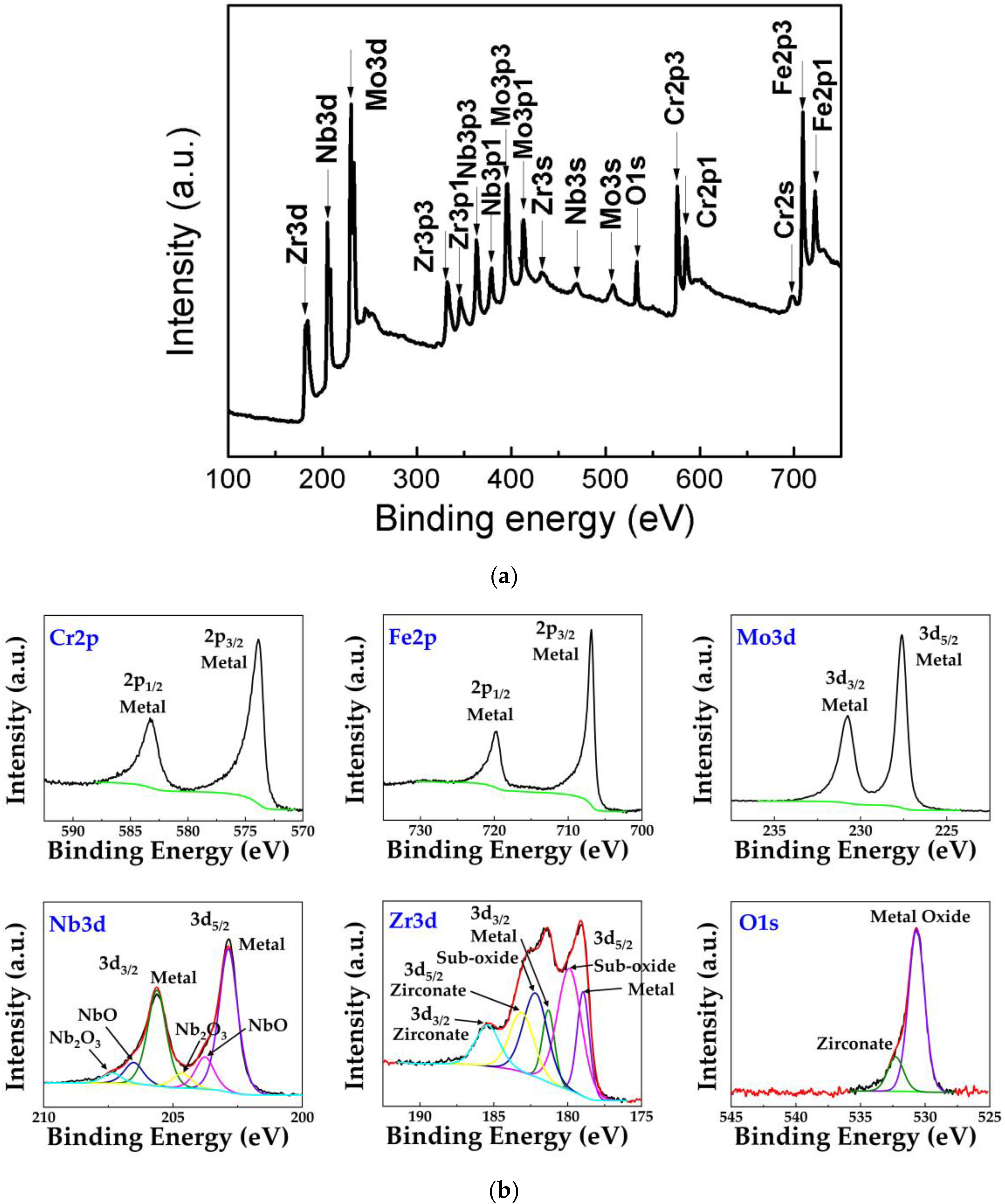
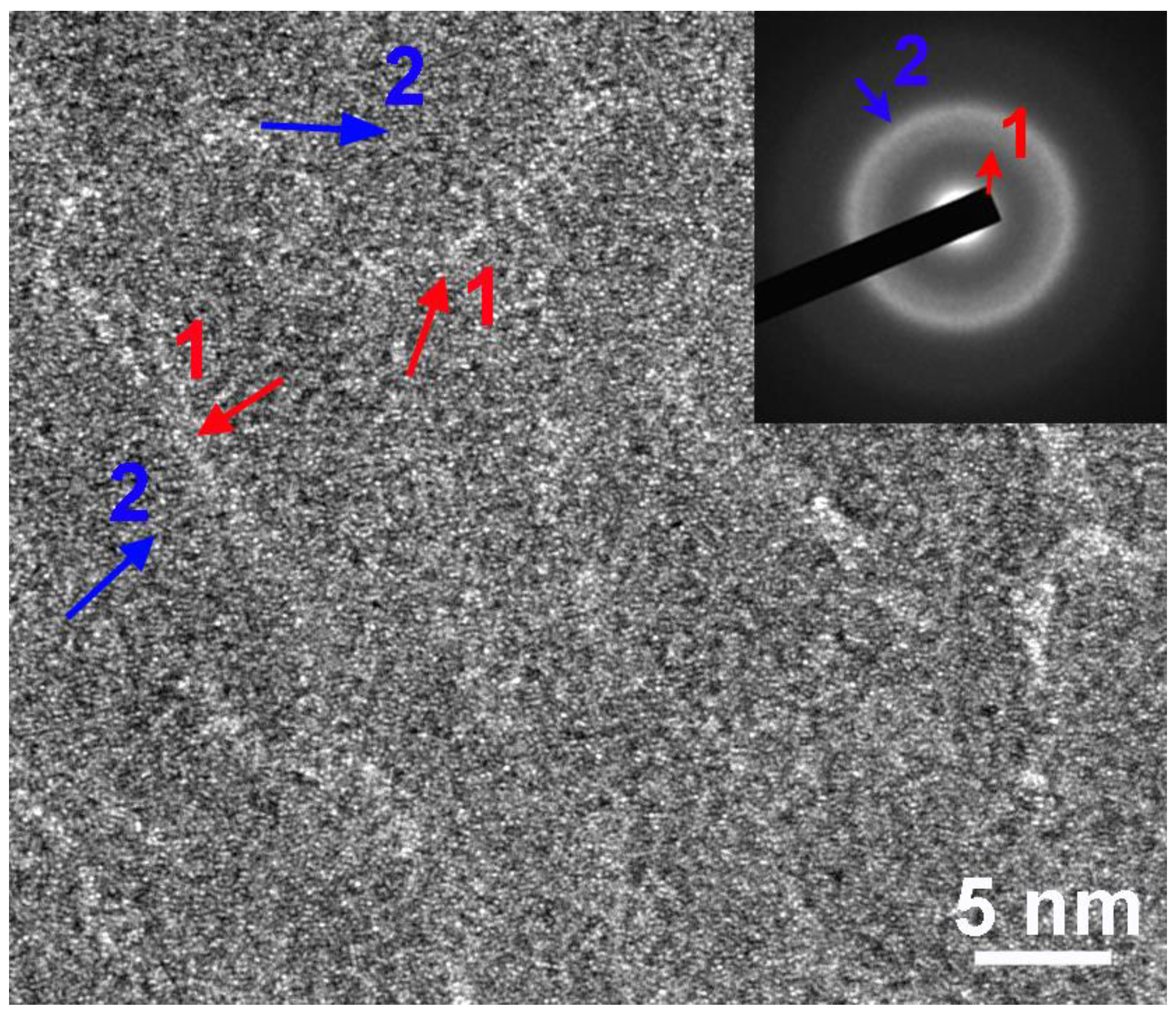
3.1. Formation and Structural Characterization of the (CrFeMoNbZr)Ox Thin Films

The thin films were deposited by magnetron sputtering technique. X-ray photoelectron spectrum (XPS) analysis was used to determine the thin film composition. To obtain the relatively accurate result, the measurement was performed in the thin film at a depth of about 100 nm below the surface. Based on the XPS full spectrum, the composition of the thin film was determined to be Cr12.7Fe17.5Mo19.0Nb13.2Zr12.4O25.2 (Figure 2a).
Figure 2b shows the chemical states of Cr, Fe, Mo, Nb, Zr and O elements measured at the thickness of 100 nm in the (CrFeMoNbZr)Ox thin film. Cr, Fe and Mo existed in their metallic states, while Nb and Zr were in both metallic and oxide states.
Figure 2c shows the chemical states of these elements measured at the surface in the (CrFeMoNbZr)Ox thin film. Most of Nb and Zr were in oxide states, whereas Mo still existed in its metallic state. Both Cr and Fe were partially oxidized. This selective oxidization of the metal components occurred because they have different affinities to oxygen [27].
Figure 3a shows the SEM image of the as-prepared thin film deposited for 100 min. The surface of the thin film was dense and smooth. In Figure 3b, the XRD pattern of the (CrFeMoNbZr)Ox thin film shows two broad diffraction peaks located at about 40.2° and 69°, indicating the formation of amorphous structure.
Figure 4 shows the high-resolution transmission electron microscopy (HRTEM) image of the thin film. In the (CrFeMoNbZr)Ox thin film, two regions were formed with different contrasts as indicated in Figure 4. Both regions showed maze-like atomic arrangements, indicating that both of them were amorphous (Figure 4). It is accepted that the contrast difference for amorphous materials comes from the mass thickness difference of different regions. The TEM sample was prepared by directly depositing the thin film onto the Cu grid coated with a holey amorphous carbon film and additional complete 2 nm thin carbon film. This assured the same thickness of the TEM sample for observation. Therefore, the contrast difference was mainly attributed to the atomic mass difference. In addition, the amount of the bright contrasted phase was small, corresponding to the inner diffraction halo with weak intensity (inset of Figure 4). The inner diffraction halo indicated a larger first-nearest neighbor distance compared with the second diffraction halo. Note that the dominant phase in the thin film was an amorphous alloy phase, as supported by the XRD pattern shown in Figure 3. Amorphous alloys usually possess a randomly dense packing structure and have more first-nearest neighbors than amorphous oxides [28,29]. It is thus reasonable to assume that the bright region 1 was an amorphous oxide phase formed by the partial oxidization of the thin film, while region 2 was the amorphous HEA matrix. Correspondingly, the inner halo was resulted by the amorphous oxide, while the outer bright one corresponded to the amorphous HEA matrix.

3.2. Mechanical Properties

Figure 5a shows the AFM-detected 3D image of the sample for detecting the height difference between the substrate and the thin film. The height difference between the two surfaces is shown in Figure 5b. It was found that the thin film deposited for 100 min had a thickness of about 1.2 μm. The sputtering rate was thus estimated to be about 0.2 nm/s, assuming that the deposition thickness increased linearly with the sputtering time.
To get reliable nanoindentation testing results, the nanoindentation displacement was set as 80 nm, about a fifteenth of the thin film thickness. Figure 5c shows the nano-indentation test results, which could be used to derive the hardness and the modulus of the as-deposited thin film. According to this load-displacement curve, the hardness of the HEA thin film was ~8.04 GPa and the elastic modulus was about 128.9 GPa. The Vickers hardness of the Zr-4 alloy substrate was ~1.93 GPa, much lower than that of the thin film. This indicated that the (CrFeMoNbZr)Ox thin film could be a protective coating deposited on the Zr-4 alloy, to enhance the substrate’s hardness and wear-resistance.

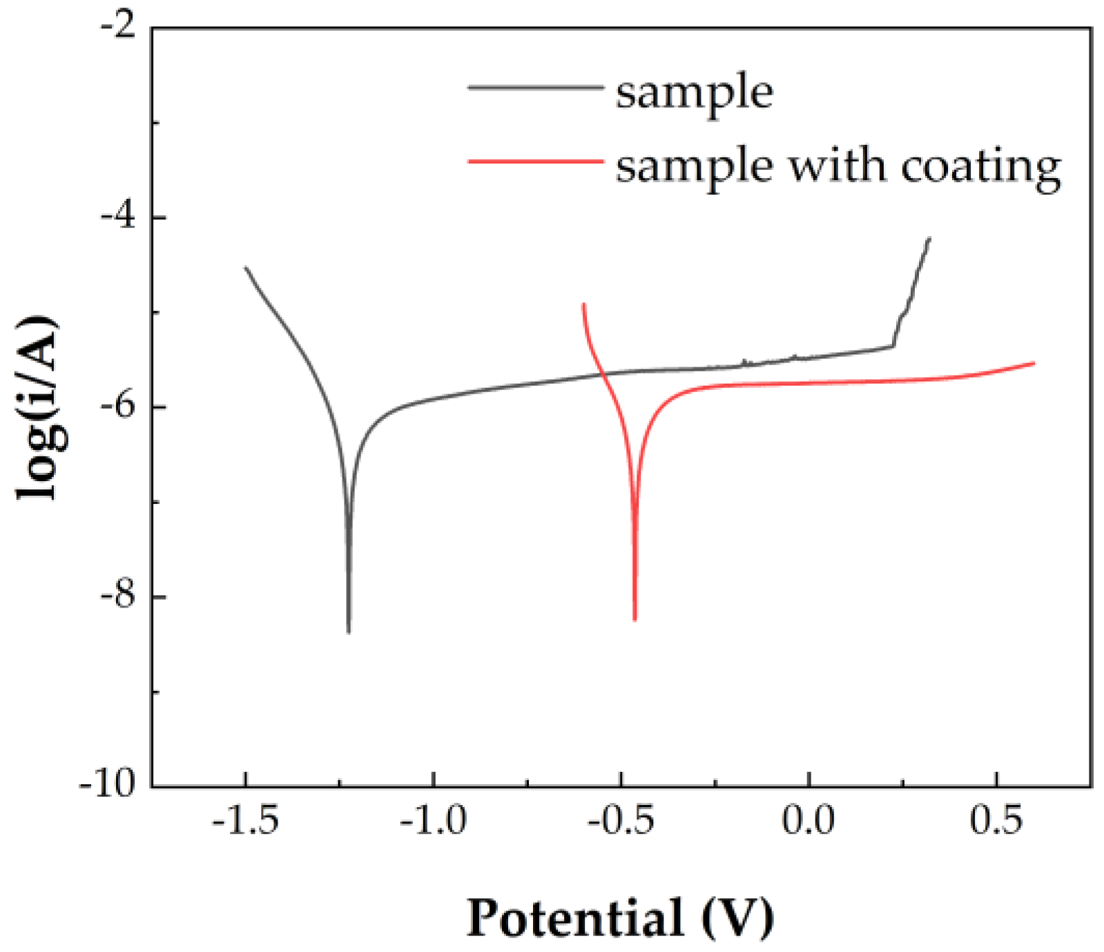
3.3. Corrosion Resistance

Figure 6 shows the potentiodynamic polarization curves of the Zr-4 alloy and the (CrFeMoNbZr)Ox thin film coated on the Zr-4 alloy substrate in 3.5 wt.% NaCl solution. The Tafel curve reflects the hydrogen evolution corrosion performance of the test samples in a neutral environment. The Ecorr of the Zr-4 alloy is −1.225 V, while the value of the coated one is −0.464 V. Besides, the pitting corrosion of the non-coated substrate started at 0.226 V. However, the Zr-4 alloy with the thin film coating did not show any sign of the pitting corrosion, even at voltages above 0.5 V. These results clearly showed that the (CrFeMoNbZr)Ox thin film enhanced the corrosion resistance of the Zr-4 alloy.

4. Discussion

Two amorphous phases are formed in the (CrFeMoNbZr)Ox thin film. The equivalent cooling rate could be as high as 106 K/s for magnetron sputtering [30]. At such a fast cooling rate of the order of 106 K/s, the nucleation and growth of crystalline phases can be avoided in most multi-component alloys, including HEA systems [12,15]. In addition, several oxygen-contained HEA systems including AlCrTaTiZr and TiZrHfCuNi thin films were easily formed in amorphous structure [12,26,31]. In the two amorphous phases, one is the dominant amorphous alloy Cr-Fe-Mo-Nb-Zr phase, while the other is an amorphous oxide phase.
In multi-component alloys, the average mixing enthalpy (ΔHmix) of a system is defined as
Δ H mix = i = 1 , i j n c i c j Ω i j
where Ω i j = 4 Δ mix AB , Δ H mix AB is the heat of mixing for a binary equiatomic AB alloy, n is the number of components, ci and cj are the atomic percentages of the ith and jth elements, respectively [32].
The atomic size mismatch (δ) is defined as
δ = i = 1 n c i ( 1 r i / i = 1 n c i r i )
where ri is the atomic radius of the ith element [33].
The composition of the thin film is Cr17.0Fe23.6Mo25.4Nb17.6Zr16.6 if oxygen is excluded from the overall composition based on the XPS analysis. The ΔHmix value of the Cr17.0Fe23.6Mo25.4Nb17.6Zr16.6 alloy can be calculated to be about −11.98 kJ/mol, based on the data shown in Figure 7 [34]. The δ value is calculated to be about 0.096 [8,34]. Both the ΔHmix and δ values indicate that the alloy system tends to form amorphous phase instead of a solid solution phase [33]. If oxygen is involved, the ΔHmix and δ values of the Cr12.7Fe17.5Mo19.0Nb13.2Zr12.4O25.2 thin film can be calculated to be −882.09 kJ/mol and 0.302, respectively [8,34]. The combination of these two values also indicates the formation of amorphous phase in the multi-component system. Note that the applicability of the Equations (1) and (2) for predicting the phase formation in oxygen-contained multi-component systems needs to be further investigated.
Oxygen is easily included in metallic materials and does not always lead to detrimental effects on the properties of the materials. A previous report showed that oxygen induced significant strengthening effect in a TiZrHfNb HEA, enhancing both the strength and ductility via ordered oxygen complexes [35]. An amorphous Co-Fe-Ta-B-O oxide matrix nanocomposite also exhibited enhanced tensile ductility by oxidizing an amorphous CoFeTaB alloy [36]. In the present Cr-Fe-Mo-Nb-Zr system, all the metal elements have high affinities to oxygen because of the large negative heats for forming the metal oxides, as shown in Figure 7 [27]. Note that the elements of Cr, Fe, Nb and Mo have several oxide states. The formation heats shown in Figure 7 were determined for their most stable oxide states in forms of Cr2O3, Fe3O4, Nb2O5 and MoO3 [27]. Among all the metal components, Nb has the largest affinity to oxygen, while Mo has the smallest affinity to oxygen. Owing to the significant difference in their affinities to oxygen, selective oxidization is supposed to occur, by forming different metal oxide states in the thin film when oxygen is introduced.
The XPS results showed that the selective oxidization of the metal components indeed occurred (Figure 2b,c). Nb and Zr were firstly oxidized, while the oxidization degree of Cr, Fe and Mo was dependent on the amount of oxygen added to the system. The surface composition was determined to be Cr8.9Fe9.9Mo12.2Nb9.5Zr12.0O47.5 by the XPS full spectrum. The oxygen content at the surface of the thin film was much higher than that of the interior of the thin film at the thickness of about 100 nm below the surface. At the surface, most of Zr and Nb were oxidized, while Cr and Fe were partially oxidized. Mo remained to be metallic (Figure 2c). Namely, a complex mixture of different metal oxide states was formed at the surface of the thin film, as shown in Figure 2c. The formation of a dense metal oxide layer at the surface should account for the enhanced corrosion resistance of the thin film, which was even better than that of the Zr-4 alloy as shown in Figure 6. In comparison, only Zr and Nb were partially oxidized, while Cr, Fe and Mo retained their metallic states in the interior of the thin film (Figure 2b).
The present amorphous (CrFeMoNbZr)Ox thin film showed high hardness of about 8.04 GPa and better corrosion resistance than the Zr-4 alloy substrate at room temperature. The hardness of the present thin film was close to that of the amorphous (AlCrTaTiZr)Ox thin films and higher than most of the HEA alloy coatings reported to date [12,26]. In addition, the selective oxidization of the metal components in the system gave rise to the formation of dual-phase nanostructure, similar to that observed in the amorphous CoFeTaBOx nanocomposite [36]. The nanostructure may enhance the fracture toughness by hindering the rapid crack propagation [36]. These combined characteristics make the (CrFeNbMoZr)Ox thin film potentially become a candidate material used for protective coatings on the Zr-based alloys for accident-tolerant fuel (ATF) claddings. However, additional tests on the high-temperature performance of the (CrFeNbMoZr)Ox thin film are required to confirm this possible applicability. For example, high-temperature oxidation resistance, high-temperature mechanical properties including coating adhesion and high-temperature phase formation are the key factors to determine the thin films’ high-temperature performance.
On the other hand, annealing the (AlCrTaTiZr)Ox thin films at 900 °C enabled the nanocrystallization of its amorphous structure and eliminated the pre-cracks in the thin films, further increasing the hardness up to 20 GPa [26]. This result indicated that partially oxidized HEA thin films with amorphous structure could be used as coatings on Zr claddings to serve at low temperature. At high temperatures, these amorphous HEA-based thin films were precursors, based on which the overall performance could be optimized by nanocrystallization. Therefore, a systematic study on the crystallization behavior and high-temperature properties of the (CrFeNbMoZr)Ox thin film will be carried out in our next-step work.
In addition, the oxygen content in the (CrFeNbMoZr)Ox system can be further adjusted by depositing the thin films in a gas mixture of O2 and Ar. In fact, it has been proven in our previous work that the oxygen content of the Co-Fe-Ta-B-O system can be adjusted by controlling the partial pressure of O2 [36,37]. Increasing the partial pressure of O2 causes an increase in the oxygen content of the thin films. Adding more oxygen to the system can increase the volume fraction of the amorphous oxide phase. Eventually, a single-phase amorphous oxide could be formed at sufficiently high oxygen contents. In the future, we will perform a systematic study on the structural evolution and properties of the (CrFeNbMoZr)Ox thin films with different oxygen contents.

5. Conclusions

In this work, thin-film (CrFeNbMoZr)Ox samples with dual-phase amorphous structures of a dominant amorphous alloy phase and a small amount of an amorphous oxide phase were prepared by magnetron sputtering. The nano indentation test showed that the thin film possessed high hardness of ~8.04 GPa and elastic modulus of ~128.9 GPa. The thin film also exhibited good corrosion resistance at room temperature.

Author Contributions

Conceptualization, N.C., X.G. and H.L.; methodology, N.C., X.G., X.W. and K.F.; formal analysis, X.G., X.Y., and K.F.; investigation, X.G., H.L., X.Y., X.W., and K.F.; resources, J.L., Y.J., K.Y., Z.Z. and N.C.; writing—original draft preparation, X.G.; writing—review and editing, N.C. and H.L.; supervision, N.C.; funding acquisition, N.C. All authors have read and agreed to the published version of the manuscript.

Funding

This research is funded by the Open fund of the State Key Laboratory of Nuclear Flue and Materials in the Nuclear Power Institute of China.

Acknowledgments

This work is sponsored by the Open fund of the State Key Laboratory of Nuclear Flue and Materials in the Nuclear Power Institute of China. One of us (Xiaoyu Gu) acknowledges the technical support from Jiajia Si, Jialun Gu and Jili Jia.

Conflicts of Interest

The authors declare no conflict of interest.

References

  1. Yeh, J.W.; Chen, S.K.; Lin, S.J.; Gan, J.Y.; Chin, T.S.; Shun, T.T.; Tsau, C.H.; Chang, S.Y. Nanostructured high-entropy alloys with multiple principal elements: Novel alloy design concepts and outcomes. Adv. Eng. Mater. 2004, 6, 299–303. [Google Scholar] [CrossRef]
  2. Cantor, B.; Chang, I.T.H.; Knight, P.; Vincent, A.J.B. Microstructural development in equiatomic multicomponent alloys. Mater. Sci. Eng. A 2004, 375, 213–218. [Google Scholar] [CrossRef]
  3. Miracle, D.B.; Senkov, O.N. A critical review of high entropy alloys and related concepts. Acta Mater. 2017, 122, 448–511. [Google Scholar] [CrossRef] [Green Version]
  4. Pickering, E.J.; Jones, N.G. High-entropy alloys: A critical assessment of their founding principles and future prospects. Int. Mater. Rev. 2016, 61, 183–202. [Google Scholar] [CrossRef] [Green Version]
  5. Miracle, D.B. High-Entropy Alloys: A Current Evaluation of Founding Ideas and Core Effects and Exploring “Nonlinear Alloys”. JOM 2017, 69, 2130–2136. [Google Scholar] [CrossRef] [Green Version]
  6. Senkov, O.N.; Wilks, G.B.; Miracle, D.B.; Chuang, C.P.; Liaw, P.K. Refractory high-entropy alloys. Intermetallics 2010, 18, 1758–1765. [Google Scholar] [CrossRef]
  7. Senkov, O.N.; Miracle, D.B.; Chaput, K.J.; Couzinie, J.-P. Development and exploration of refractory high entropy alloys-A review. Int. J. Mater. Res. 2018, 33, 3092–3128. [Google Scholar] [CrossRef] [Green Version]
  8. Zhang, Y.; Zuo, T.T.; Tang, Z.; Gao, M.C.; Dahmen, K.A.; Liaw, P.K.; Lu, Z.P. Microstructures and properties of high-entropy alloys. Prog. Mater Sci. 2014, 61, 1–93. [Google Scholar] [CrossRef]
  9. Feng, X.B.; Zhang, J.Y.; Xia, Z.R.; Fu, W.; Wu, K.; Liu, G.; Sun, J. Stable nanocrystalline NbMoTaW high entropy alloy thin films with excellent mechanical and electrical properties. Mater. Lett. 2018, 210, 84–87. [Google Scholar] [CrossRef]
  10. Gorban, V.F.; Andreev, A.A.; Shaginyan, L.R.; Firstov, S.A.; Karpets, M.V.; Danilenko, N.I. High-Entropy Coatings-Structure and Properties. J. Superhard Mater. 2018, 40, 88–101. [Google Scholar] [CrossRef]
  11. Chen, T.K.; Wong, M.S.; Shun, T.T.; Yeh, J.W. Nanostructured nitride films of multi-element high-entropy alloys by reactive DC sputtering. Surf. Coat. Tech. 2005, 200, 1361–1365. [Google Scholar] [CrossRef]
  12. Li, J.; Huang, Y.; Meng, X.; Xie, Y. A Review on High Entropy Alloys Coatings: Fabrication Processes and Property Assessment. Adv. Eng. Mater. 2019, 21, 1900343. [Google Scholar] [CrossRef]
  13. Zhao, F.; Song, Z.X.; Zhang, G.F.; Hou, X.D.; Deng, D.W. Effects of substrate bias on structure and mechanical properties of AlCrTiWNbTa coatings. Surf. Eng. 2013, 29, 778–782. [Google Scholar] [CrossRef]
  14. Tunes, M.A.; Vishnyakov, V.M.; Camara, O.; Greaves, G.; Edmondson, P.D.; Zhang, Y.; Donnelly, S.E. A candidate accident tolerant fuel system based on a highly concentrated alloy thin film. Mater. Today Energy 2019, 12, 356–362. [Google Scholar] [CrossRef] [Green Version]
  15. Fritze, S.; Koller, C.M.; von Fieandt, L.; Malinovskis, P.; Johansson, K.; Lewin, E.; Mayrhofer, P.H.; Jansson, U. Influence of Deposition Temperature on the Phase Evolution of HfNbTiVZr High-Entropy Thin Films. Materials 2019, 12, 587. [Google Scholar] [CrossRef] [Green Version]
  16. Zhang, Y.; Tunes, M.A.; Crespillo, M.L.; Zhang, F.; Boldman, W.L.; Rack, P.D.; Jiang, L.; Xu, C.; Greaves, G.; Donnelly, S.E.; et al. Thermal stability and irradiation response of nanocrystalline CoCrCuFeNi high-entropy alloy. Nanotechnology 2019, 30, 294004. [Google Scholar] [CrossRef]
  17. Al-Olayyan, Y.; Fuchs, G.E.; Baney, R.; Tulenko, J. The effect of Zircaloy-4 substrate surface condition on the adhesion strength and corrosion of SiC coatings. J. Nucl. Mater. 2005, 346, 109–119. [Google Scholar] [CrossRef]
  18. Alat, E.; Motta, A.T.; Comstock, R.J.; Partezana, J.M.; Wolfe, D.E. Ceramic coating for corrosion (c3) resistance of nuclear fuel cladding. Surf. Coat. Technol. 2015, 281, 133–143. [Google Scholar] [CrossRef] [Green Version]
  19. Alat, E.; Motta, A.T.; Comstock, R.J.; Partezana, J.M.; Wolfe, D.E. Multilayer (TiN, TiAlN) ceramic coatings for nuclear fuel cladding. J. Nucl. Mater. 2016, 478, 236–244. [Google Scholar] [CrossRef] [Green Version]
  20. Tunes, M.A.; da Silva, F.C.; Camara, O.; Schon, C.G.; Sagas, J.C.; Fontana, L.C.; Donnelly, S.E.; Greaves, G.; Edmondson, P.D. Energetic particle irradiation study of TiN coatings: Are these films appropriate for accident tolerant fuels? J. Nucl. Mater. 2018, 512, 239–245. [Google Scholar] [CrossRef] [Green Version]
  21. Imtyazuddin, M.; Mir, A.H.; Tunes, M.A.; Vishnyakov, V.M. Radiation resistance and mechanical properties of magnetron-sputtered Cr2AlC thin films. J. Nucl. Mater. 2019, 526, 151742. [Google Scholar] [CrossRef]
  22. Mráz, S.; Tyra, M.; to Baben, M.; Hans, M.; Chen, X.; Herrig, F.; Lambrinou, K.; Schneider, J.M. Thermal stability enhancement of Cr2AlC coatings on Zr by utilizing a double layer diffusion barrier. J. Eur. Ceram. Soc. 2020, 40, 1119–1124. [Google Scholar] [CrossRef]
  23. Khatkhatay, F.; Jiao, L.; Jian, J.; Zhang, W.R.; Jiao, Z.J.; Gan, J.; Zhang, H.B.; Zhang, X.H.; Wang, H.Y. Superior corrosion resistance properties of TiN-based coatings on Zircaloy tubes in supercritical water. J. Nucl. Mater. 2014, 451, 346–351. [Google Scholar] [CrossRef]
  24. Terrani, K.A. Accident tolerant fuel cladding development: Promise, status, and challenges. J. Nucl. Mater. 2018, 501, 13–30. [Google Scholar] [CrossRef]
  25. Zinkle, S.J.; Terrani, K.A.; Gehin, J.C.; Ott, L.J.; Snead, L.L. Accident tolerant fuels for LWRs: A perspective. J. Nucl. Mater. 2014, 448, 374–379. [Google Scholar] [CrossRef]
  26. Lin, M.-I.; Tsai, M.-H.; Shen, W.-J.; Yeh, J.-W. Evolution of structure and properties of multi-component (AlCrTaTiZr)O-x films. Thin Solid Films 2010, 518, 2732–2737. [Google Scholar] [CrossRef]
  27. Smithells, C.; Gale, W.; Totemeier, T. Smithells Metals Reference Book, 8th ed.; Elsevier Butterworth-Heinemann: Oxford, UK, 2004. [Google Scholar]
  28. Cheng, Y.Q.; Ma, E. Atomic-level structure and structure-property relationship in metallic glasses. Prog. Mater. Sci. 2011, 56, 379–473. [Google Scholar] [CrossRef]
  29. Kittel, C.; McEuen, P.; McEuen, P. Introduction to Solid State Physics; Wiley New York: New York, NY, USA, 1996. [Google Scholar]
  30. Ohring, M. Materials Science of Thin Films: Deposition and Structure, 2nd ed.; Academic Press: San Diego, CA, USA, 2002; ISBN 0-12r-r524975-6. [Google Scholar]
  31. Zhao, S.; Wang, P.; Cheng, X.; Zhang, Y.; Wen, Z.; Zhang, Q.; Yao, K.-F.; Chen, N.; Wang, W.-H. Anomalous low-temperature transport property of oxygen containing high-entropy Ti-Zr-Hf-Cu-Ni metallic glass thin films. Sci. China Mater. 2019, 62, 907–912. [Google Scholar] [CrossRef] [Green Version]
  32. Zhang, Y.; Zhou, Y.J.; Lin, J.P.; Chen, G.L.; Liaw, P.K. Solid-solution phase formation rules for multi-component alloys. Adv. Eng. Mater. 2008, 10, 534–538. [Google Scholar] [CrossRef]
  33. Guo, S.; Hu, Q.; Ng, C.; Liu, C.T. More than entropy in high-entropy alloys: Forming solid solutions or amorphous phase. Intermetallics 2013, 41, 96–103. [Google Scholar] [CrossRef]
  34. Takeuchi, A.; Inoue, A. Classification of bulk metallic glasses by atomic size difference, heat of mixing and period of constituent elements and its application to characterization of the main alloying element. Mater. Trans. 2005, 46, 2817–2829. [Google Scholar] [CrossRef] [Green Version]
  35. Lei, Z.; Liu, X.; Wu, Y.; Wang, H.; Jiang, S.; Wang, S.; Hui, X.; Wu, Y.; Gault, B.; Kontis, P.; et al. Enhanced strength and ductility in a high-entropy alloy via ordered oxygen complexes. Nature 2018, 563, 546. [Google Scholar] [CrossRef] [PubMed]
  36. Huang, L.; Tang, X.; Jiang, G.; Fang, K.; Yao, K.; Zhang, Z.; Chen, N.; Shan, Z. A high-strength Co–Fe–Ta–B metallic-glass phase enabled tensile plasticity in Co–Fe–Ta–B–O oxide glass matrix nanocomposites. Appl. Phys. Lett. 2020, 116, 081903. [Google Scholar] [CrossRef]
  37. Chen, N.; Fang, K.; Zhang, H.; Zhang, Y.; Liu, W.; Yao, K.; Zhang, Z. Amorphous magnetic semiconductors with Curie temperatures above room temperature. J. Semicond. 2019, 40, 081510. [Google Scholar] [CrossRef]
Figure 1. Device with sample (WE) used in electrochemical testing (a), the schematic diagram of the working device (b) and the test circuit diagram (c).
Metals 10 00599 g001
Figure 2. (a) X-ray photoelectron (XPS) full spectrum, (b) XPS of each element at the thickness of 100 nm below the surface of the (CrFeMoNbZr)Ox thin film and (c) XPS of each element measured at the surface of the (CrFeMoNbZr)Ox thin film.
Metals 10 00599 g002aMetals 10 00599 g002b
Figure 3. (a) The SEM image and (b) the XRD pattern of the sample prepared by magnetron sputtering.
Metals 10 00599 g003
Figure 4. HRTEM image of the CrFeMoNbZrOx thin film. The inset is the SAED pattern of the thin film.
Metals 10 00599 g004
Figure 5. (a) The 3D AFM image of the as-deposited thin film. (b) The height difference profile between the substrate and the thin film. (c) The load-displacement curve of the thin film.
Metals 10 00599 g005aMetals 10 00599 g005b
Figure 6. Tafel curves of the high entropy alloy (HEA) thin film and the Zr-4 alloy substrate in 3.5 wt.% NaCl solution at room temperature.
Metals 10 00599 g006
Figure 7. The heats of mixing between the pairs of metal components and the heats for forming different stable metal oxides (unit: KJ/mole) in the Cr-Fe-Nb-Mo-Zr-O system.
Metals 10 00599 g007

