Article

Applicability of Hybrid Built-Up Wide Flange Steel Beams

1
Department of Civil and Environmental Engineering, Nazarbayev University, Qabanbay Batyr Ave. 53, Nur-Sultan 010000, Kazakhstan
2
Department of Architectural Engineering, University of Seoul, 163 Seoulsiripdae-ro, Dongdaemun-gu, Seoul 02504, Korea
3
Department of Architectural Engineering, Chungbuk National University, 1 Chungdae-ro, Seowon-gu, Cheongju, Chungbuk 28644, Korea
*
Author to whom correspondence should be addressed.
Metals 2020, 10(5), 567; https://doi.org/10.3390/met10050567
Submission received: 19 March 2020 / Revised: 30 March 2020 / Accepted: 8 April 2020 / Published: 27 April 2020
(This article belongs to the Special Issue Design of Welded Steel Structures)

Abstract

:
To accommodate growing demands on either heavy steel structures or unique buildings with irregular configurations, built-up wide-flange steel (BWS) beams are being popularly used in modern steel construction. In current fabrication practices of BWS members, high-performance steels produced in steelmaking factories under the thermo-mechanical control process (TMCP) are typically utilized to achieve proper welding performances. However, since its basic unit price is quite higher than typical hot-rolled steel materials, this study introduced a hybrid BWS section for cost saving with no performance degradation, where high-performance TMCP steel was used in flanges, and conventional hot-rolled steel was adopted in web plate. To verify the tensile performances of a hybrid BWS section with non-uniform properties, split T tension and Charpy impact tests were conducted, and flexural tests were also carried out on hybrid and homogeneous BWS beam members. On this basis, it was confirmed that the structural performance of the hybrid BWS member is comparable with that of the conventional one with a uniform section property.

1. Introduction

Steel and concrete are considered as popular construction materials in modern industries around the world. In current concrete construction, the cost of temporary works and relevant input workforce are becoming much more critical, rather than that of construction materials. On the other hand, since the unit price of structural steel is much higher than conventional reinforced concrete, the amount of materials consumed in gravity and lateral force-resisting frames is a key factor in determining the total cost of steel construction [1,2]. In recent years, customized built-up wide-flange steel (BWS) members are being frequently used when suitable steel section size is not available from the list of the standard wide flange sections. In the fabrication practices of BWS beams, high-performance steels produced under the thermo-mechanical control process (TMCP) are generally preferred to achieve proper welding performances, but this is considered as the main reason of increasing the cost in high-rise building construction. It is; therefore, necessary to reduce the manufacturing cost of individual BWS members to achieve the price competitiveness in the market [3,4] in terms of price per load-carrying capacity. To this end, this study aims to examine the applicability of a hybrid BWS beam member for cost saving with no performance degradation by utilizing high-performance TMCP steel in flanges and conventional hot-rolled steel in web plate, respectively. In addition, a simplified welding detail was applied for improved fabricability of BWS sections.
Figure 1 shows the motivation of this study, “P” multiplex project under construction in Seoul, South Korea, where the proposed hybrid BWS members are being applied to high-rise office buildings, a hotel and a shopping mall. According to feasibility studies conducted by the contractor, it appeared that more than 10% of its total construction cost can be reduced by introducing hybrid BWS members instead of the conventional one with homogeneous section properties. In the proposed method, as shown in Figure 2 and Table 1, the top and bottom flanges of BWS members are made of the high-performance steel, Grade SM490TMC, while Grade SM490A, which is a typical hot-rolled steel, is used as the web plate. Note that more detailed information of the steel materials is provided in the next section. Welding performances between two steel plates with different performance grades were evaluated via the direct tension tests of split T specimens [2,5,6], and Charpy impact tests were also conducted to examine the toughness of hybrid BWS sections with non-uniform properties. In addition, flexural tests and corresponding nonlinear finite element analyses were conducted on hybrid and homogeneous BWS beam members to verify the applicability of the proposed hybrid BWS section.

2. Details on Structural Steel and Welding

2.1. Background of Industrial Standards

As reported in the handbook of comparative world steel standards [7,8], each country adopts its own industrial standard (e.g., ASTM (USA), CSA (Canada), BSI (UK), CEN (Europe), DIN (Germany), GOST (Russia), JIS (Japan), KS (South Korea), and so on). This means there is no straightforward way to find the so-called equivalent standard among them against all the steel grades and other sub-categories depending on chemical composition, application purpose, and welding performance. For example, ASTM mainly classifies the steel materials based on chemical composition, properties, and performance, such as carbon steel, high-strength low-alloy steel, hot- and cold-rolled steel and so on. For CEN, the production method is a key criterion, such as hot-rolled, thermo-mechanically rolled and quench and tempered steels. Unlike American and European standards, KS and JIS industrial standards in South Korea and Japan classify the structural steels basically by means of the application purpose: Grade SS (general structure), Grade SM (welded structure), and Grade SHN (building structures subjected to seismic design). Thus, it is hard to find an exact match with those specified in Western standards. Thus, some details of the Korean industrial standard (KS) should be presented in this section. As shown in Table 1, the first two capital letters of the Korean steel standard indicate the application types of steel materials, which is then followed by the tensile strength grade. For example, SM490 denotes hot-rolled steel materials for welded structures with the specified tensile strength ( F u ) of 490 MPa and yielding strength ( F y ) ranged from 295 to 325 MPa, depending on the plate thickness ( T ), respectively. The next capital letter (Classes A, B, or C) right after the strength grade indicates the absorption energy (or toughness) obtained from Charpy impact test [9,10]. Before the Tohoku earthquake occurred in Japan, the impact performance of steel materials was not a critical concern, but it is considered at present as an important factor in the seismic zones [11]. In terms of Charpy absorbed energy, which is an indicator of the impact resisting performance or toughness, there is no lower limit for Class A, but the minimum values of Classes B and C are 27 and 47 J, respectively, at 0 °C temperature condition [12]. Classes B and C offer superior impact resistances in welded connections and thus those grades are generally used in built-up wide-flange steel members. However, since their prices are quite higher than Class A (approximately more than 20%), this study aims to examine the possibility of replacing it with Class A in the web plate of a BWS section, as shown in Figure 1. For the flanges of a BWS member, which is the main resistance element to flexure, their thickness is typically larger than that of the web plate. However, when the plate thickness gets thicker [13,14,15,16], even for the SM-type steel for welded structures, welding performance degradations are inevitable due to its high carbon content. In the KS standard, consequently, the specified yield strength of the SM type steels decreases as the plate thickness increases. Therefore, high-performance TMCP steels (SM490TMC in this study) are generally used to fabricate the top and bottom flanges of a BWS member [10,13,14,15], because no strength and welding performance degradation is expected in TMCP steels due to a special metallurgical process combining forging or rolling with well controlled thermal cycles of heating and cooling, which can guarantee lower carbon content with high strength and ductility than the SM steels.
In this study, to evaluate the applicability of the hybrid BWS section made of SM490TMC flanges and SM490A web plate, the welding and impact energy absorption performances between the two different steels were evaluated by testing, and the structural performances of BWS beams with conventional homogeneous and hybrid sections were also evaluated in detail.

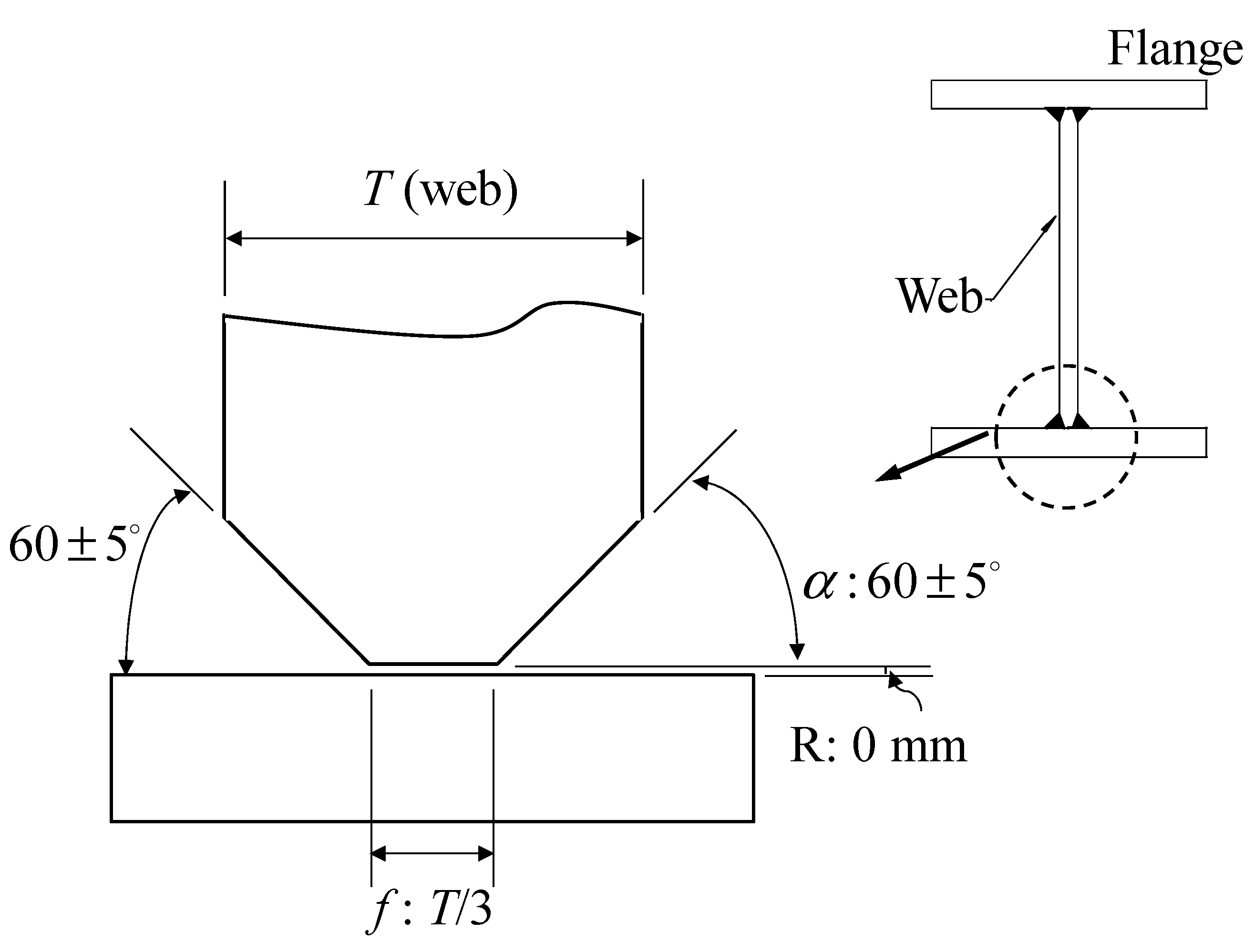
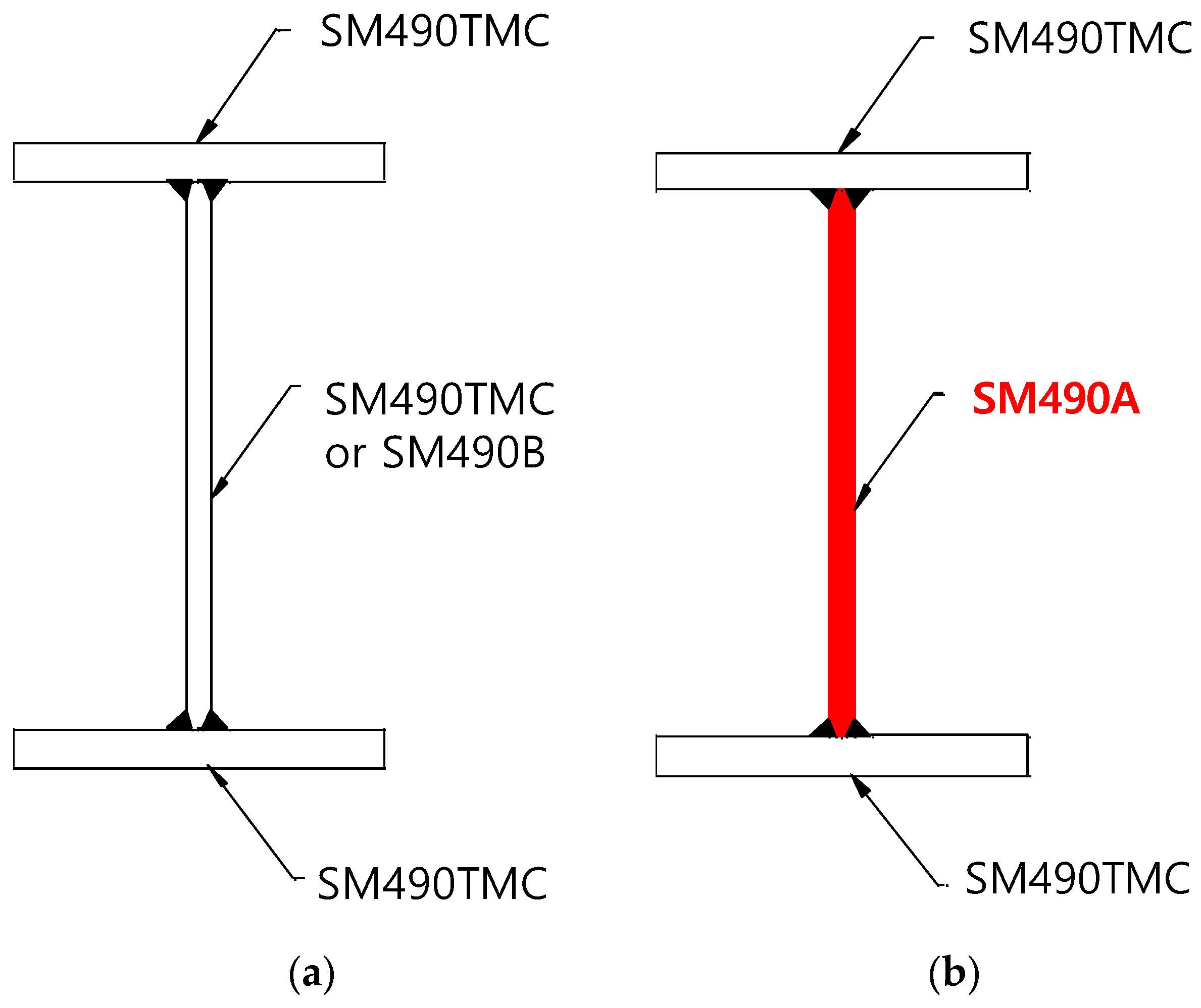
2.2. Simplified Welding Details

Welding details in Korean practice have commonly conducted based on AWS A1.1/D1:2010 (American Welding Society) [17]. To secure the proper welding quality of steel connections for factory-based mass production, the submerged arc welding (SAW) method with K groove is generally considered to be suitable for the connections between flanges and web plates. In addition, several different details are available on the root opening ( f ), groove angle ( α ) and root face ( R ), and specific welding postures are also specified for the SAW method [17]. When large hybrid BWS members are manufactured in a prefabrication factory, the welding heat input and travel speed are very important factors in determining the economic feasibility. Figure 2 showed the simplified welding details addressed in this study. In this simplified detail, the groove angle ( α ) and length of root face ( R ) are set to be 60 degrees and 0 mm, respectively, which are exactly the same with the details presented in AWS A1.1/D1:2010, but the root opening ( f ) was modified as one-third of plate thickness ( T ). This is expected to be larger than the maximum root opening (5 mm) allowed in AWS A1.1/D1:2010 for web plates, with 20 mm thickness used in this study. All the connections in this study were welded by using the SAW method, with the simplified details presented in Figure 2. Welding rods 4.8 mm in diameter were used in this study, and their yield and tensile strengths were measured at 543 and 612 MPa, respectively. In addition, the current (A) and voltage (V) provided from a welding power supply were carefully controlled within 650 to 750 A and 28 to 32 V, respectively. The welding travel speed and heat input were 700 mm/min and 17 KJ/Cm on average, respectively. The inter-pass temperature was well controlled under 92 °C, and 4-pass multi-layer welding was applied to all the test specimens.

3. Material Tests

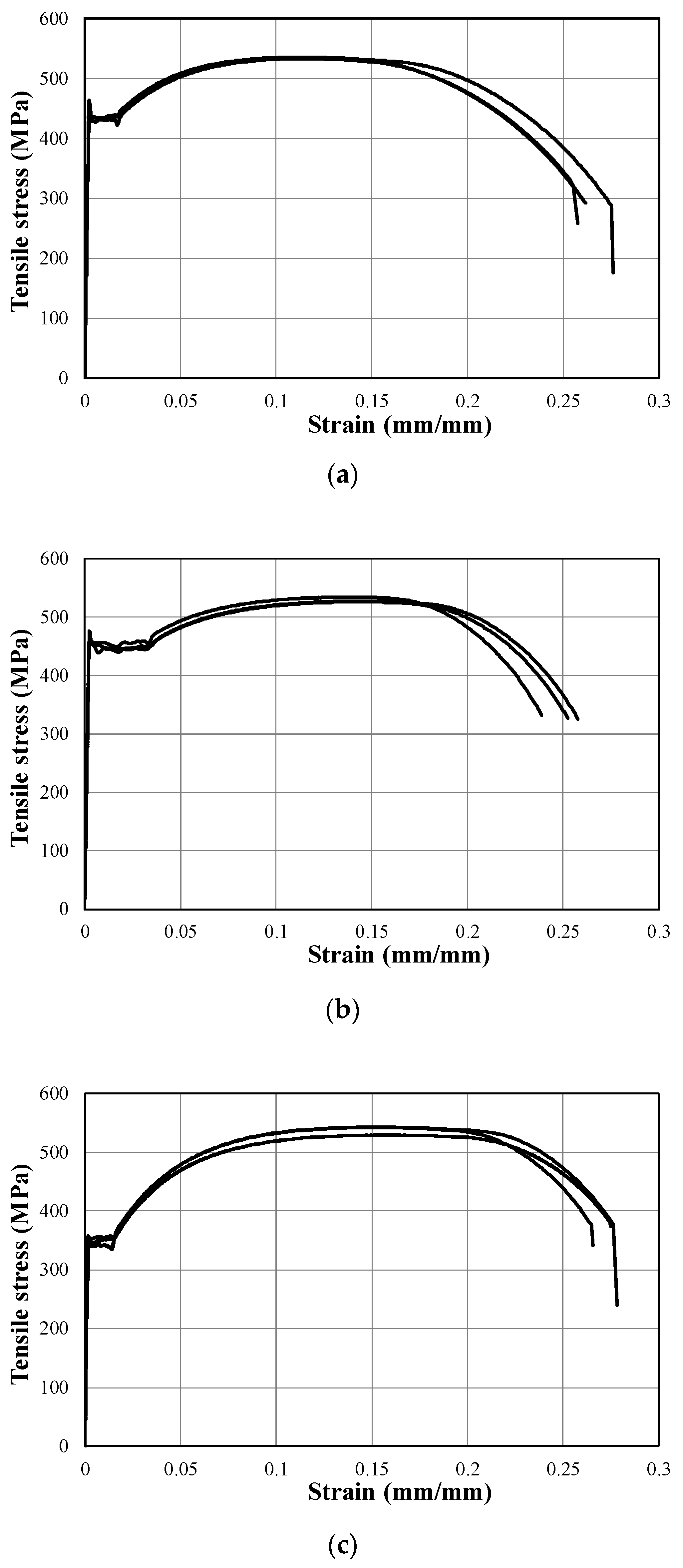
3.1. Uniaxial Tensile Test

Uniaxial tension tests were conducted on three steel coupons extracted from the base steel plates for each series: Grade SM490TMC with 30T (i.e., 30 mm in thickness) to be used as the top and bottom flanges of the BWS sections as shown in Figure 1; and SM490TMC and SM490A with 20T (20 mm in thickness) were used as the web plates of the homogeneous and hybrid BWS sections, respectively. All the specimens were carefully prepared and tested according to ASTM E8 [18] and KS B 0801 [19], and the test results are summarized in Table 2.
Figure 3 shows the uniaxial tensile stress–strain relationships obtained from the coupon tests. All the steel materials tested in this study fully satisfied the required performances specified in the standard regardless of the grades and thicknesses. The Grade SM490TMC steel of 20 and 30 mm thicknesses showed higher yield strengths compared to Grade SM490A, and no strength degradation of the TMCP steels was observed depending on the plate thickness, as specified and intended in the KS standard. While Grade SM490A with the same thickness showed somewhat smaller yield strength, there was no clear difference in terms of the tensile strength and ductility. The deviations of the yield and tensile strengths within the same grade were distributed within 5%, and the yield to tensile strength ratios ( F y / F u ) were also under 85% for all the cases, which is fully satisfactory for the current standards. The uniaxial tension test results were compared with the direct tensile test at the welding joint to validate the proposed welding performance, and the structural behavior would be based on the uniaxial tension test results unless the welding performance was inferior to that with the existing method.

3.2. Direct Tensile Test at Welding Joint

To evaluate the performance of welded connections with non-uniform section properties and simplified details suggested in this study, split T test specimens were fabricated and tested as shown in Figure 4. A pair of the specimens were considered for each of two series specimens: U series specimens are the welded connection between the plates with the same material property (i.e., SM490TMC with 30 (30T) and 20 mm (20T) thickness); and H series specimens had non-uniform properties (i.e., the combination of SM490TMC with 30T and SM490A with 20T).
The direct tensile behaviors of the spilt T specimens were measured using a load cell embedded in the universal testing machine (UTM), with 3000 kN capacity, and a LVDT installed on the side of specimen, as shown in Figure 5. Figure 6 shows the tensile stress–strain curve of each series together with the results of the base materials with no welding. It can be clearly confirmed that the performances of the welded connections were comparable with those of the base materials without welding, but the deformation capacity of the welded specimens decreased by 35%. No clear deficiency of the tensile performance was observed in the hybrid welded connections compared to the case made of only the high-performance steels. In addition, the failure modes of all the specimens were very similar with those observed in the base material tests, where all the specimens were fractured outside of the welding joint region.

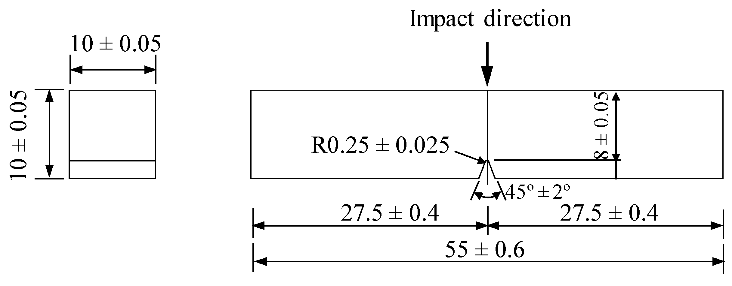
3.3. Charpy Impact Test

Even though the structural steel is considered as a ductile construction material with high strength and superior plastic deformational capacity, it can be abruptly fractured when the material is subjected to dynamic impact loading at low temperatures [20]. Such an impact performance is usually evaluated by the Charpy V-notch test [9], in which the key criterion is the energy absorption capacity under an impact. As mentioned, Grade SM490B, SM490C or TMCP steel is preferred in the current practices of BWS members, and thus the impact performance (or toughness) of Grade SM490A should be verified for the application of the hybrid BWS section. For Charpy impact tests, as shown in Figure 7, a total of 15 standard samples with 10 mm square section were carefully prepared, where V-notch with 2 mm depth and inclination angle of 45° were introduced at the middle of the specimens based on the KS B 0809 [21] and ASTM E 23 [22]. This test program includes three series—SM490A-20T, SM490TMC-30T, and SM490TMC-20T—where five tests were conducted for each series. The specimens were carefully sampled along the rolling direction from the original base plates. Impact loads were applied to the test specimens by using an impact hammer under the temperature condition of 0 °C [22,23]. The Charpy absorbed energy (E) can be calculated, as follows:
E = W R ( cos β cos α )
where W is the weight applied by the impact hammer (N), R is the distance from the axis of rotation to the impact point, α is the winding angle, and β is the angle of failure line. Among them, W, R and α are known values before testing, thus, the Charpy absorbed energy (E) can be estimated with β observed from testing, and thus the toughness of materials can be calculated by dividing the accumulated energy by the notch area. The Charpy impact test results are presented in Table 3, and it shows that the toughness of the high performance TMCP steels are more than four times higher compared to that of SM490A. However, all the specimens made of Grade SM490A fully satisfy the lower limit of toughness to be accepted as SM490TMC or SM490C, which is specified as 27 and 47 J for Grades SM490TMC and SM490C, respectively.

4. Structural Performance of Built-Up Wide-Flange Steel Beam

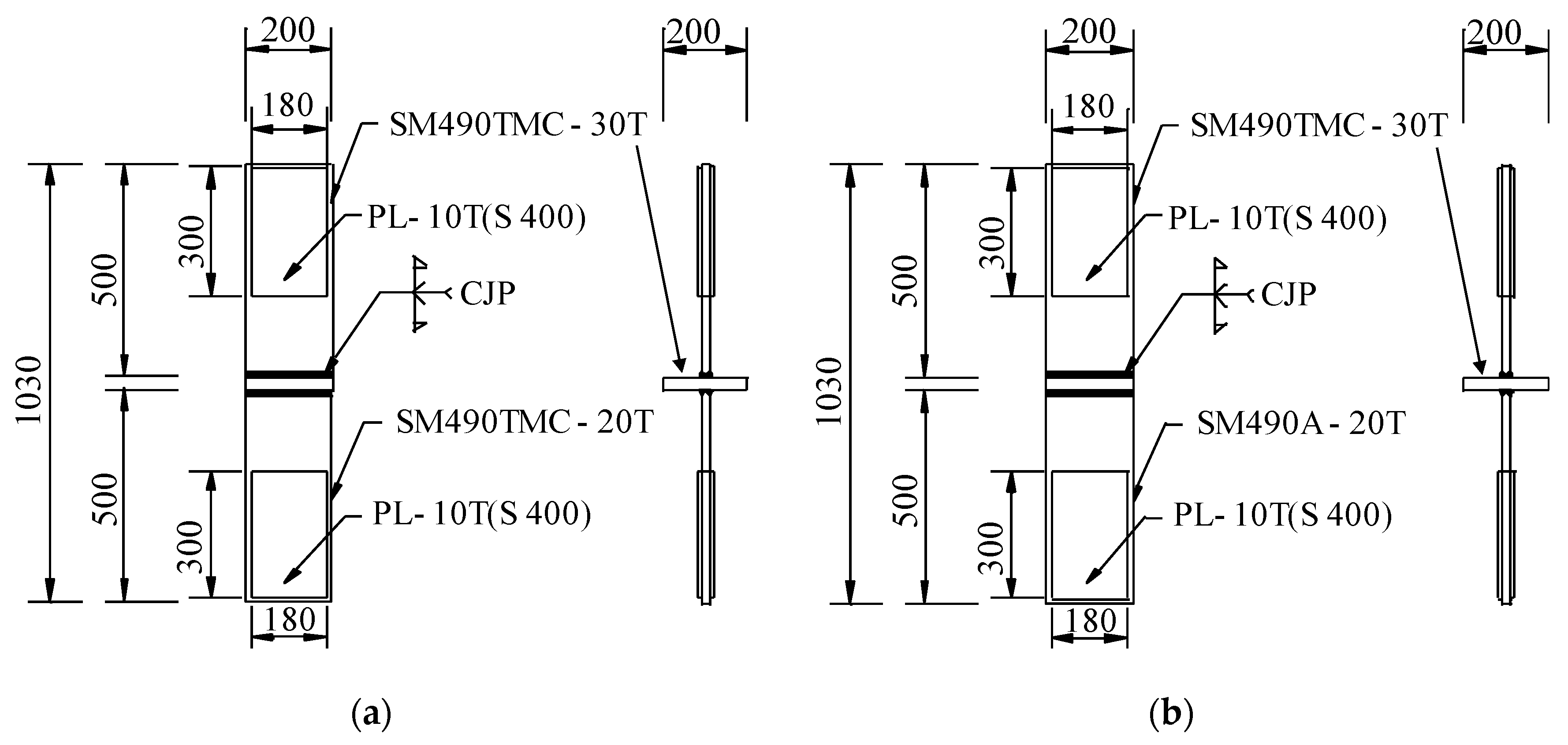
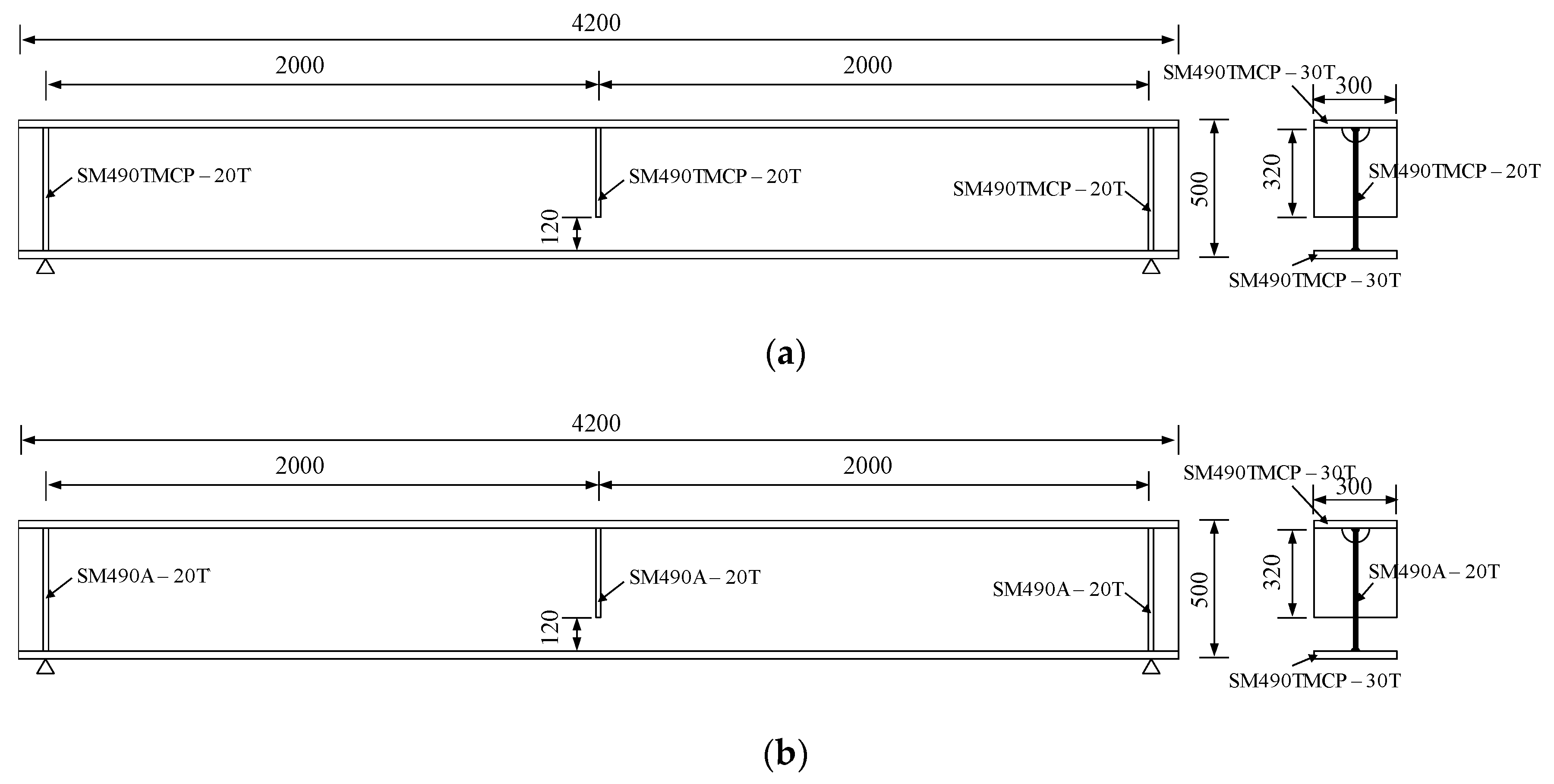
4.1. Specimen Details
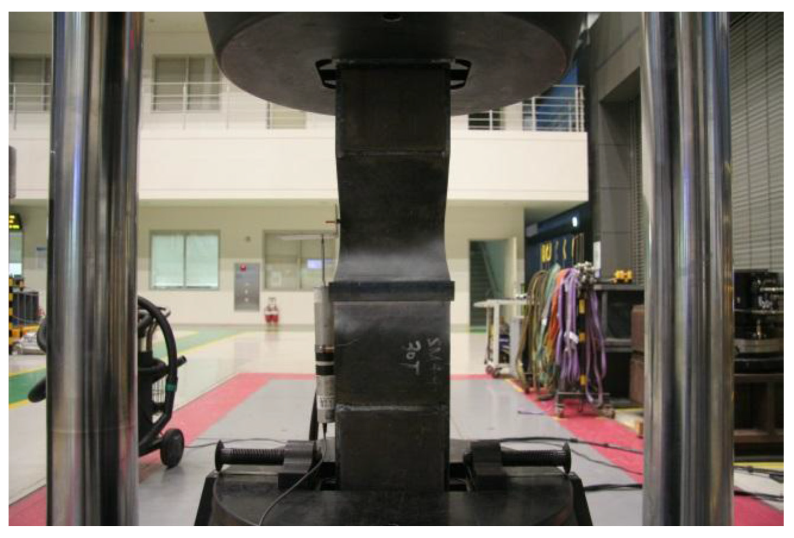
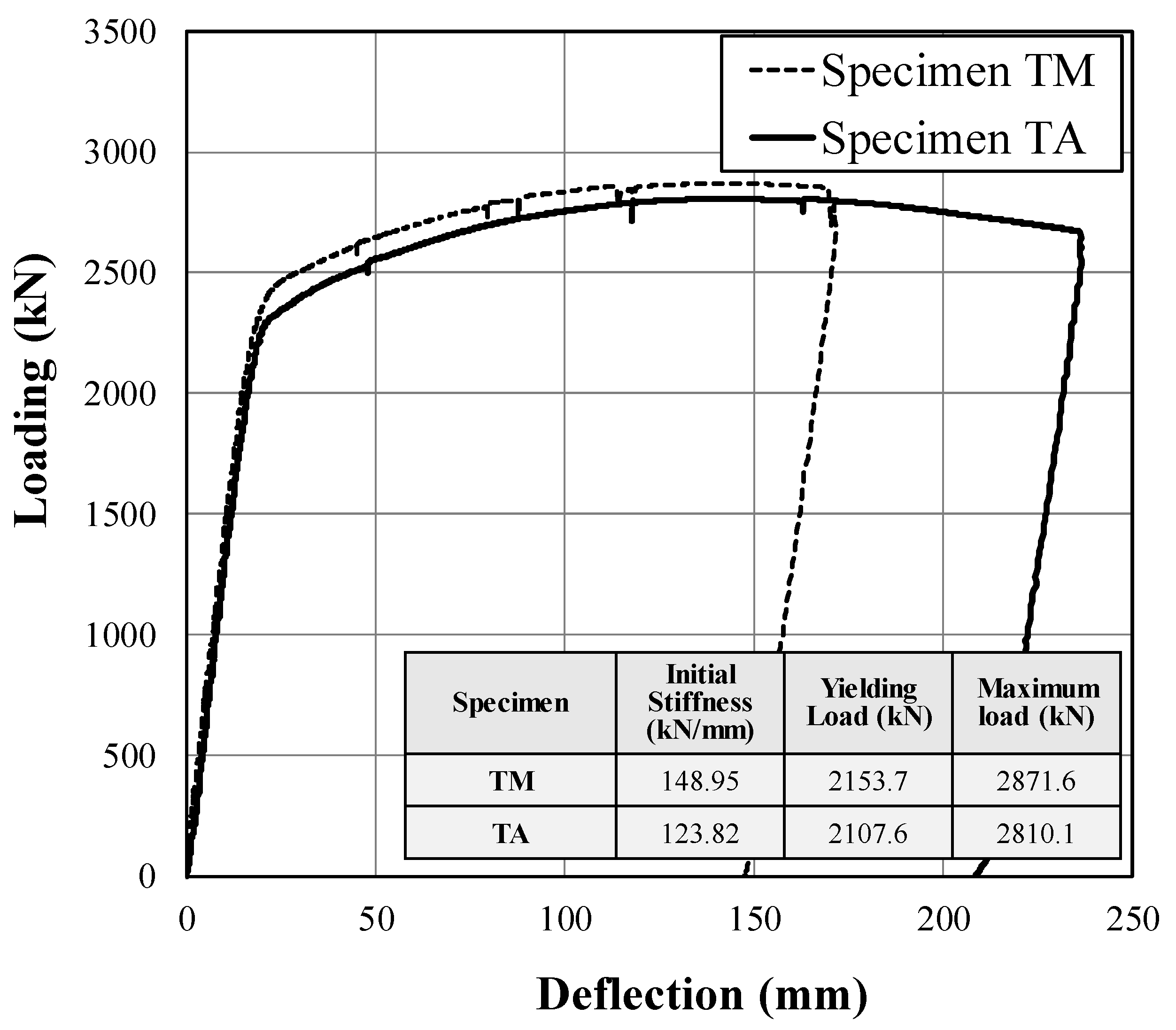
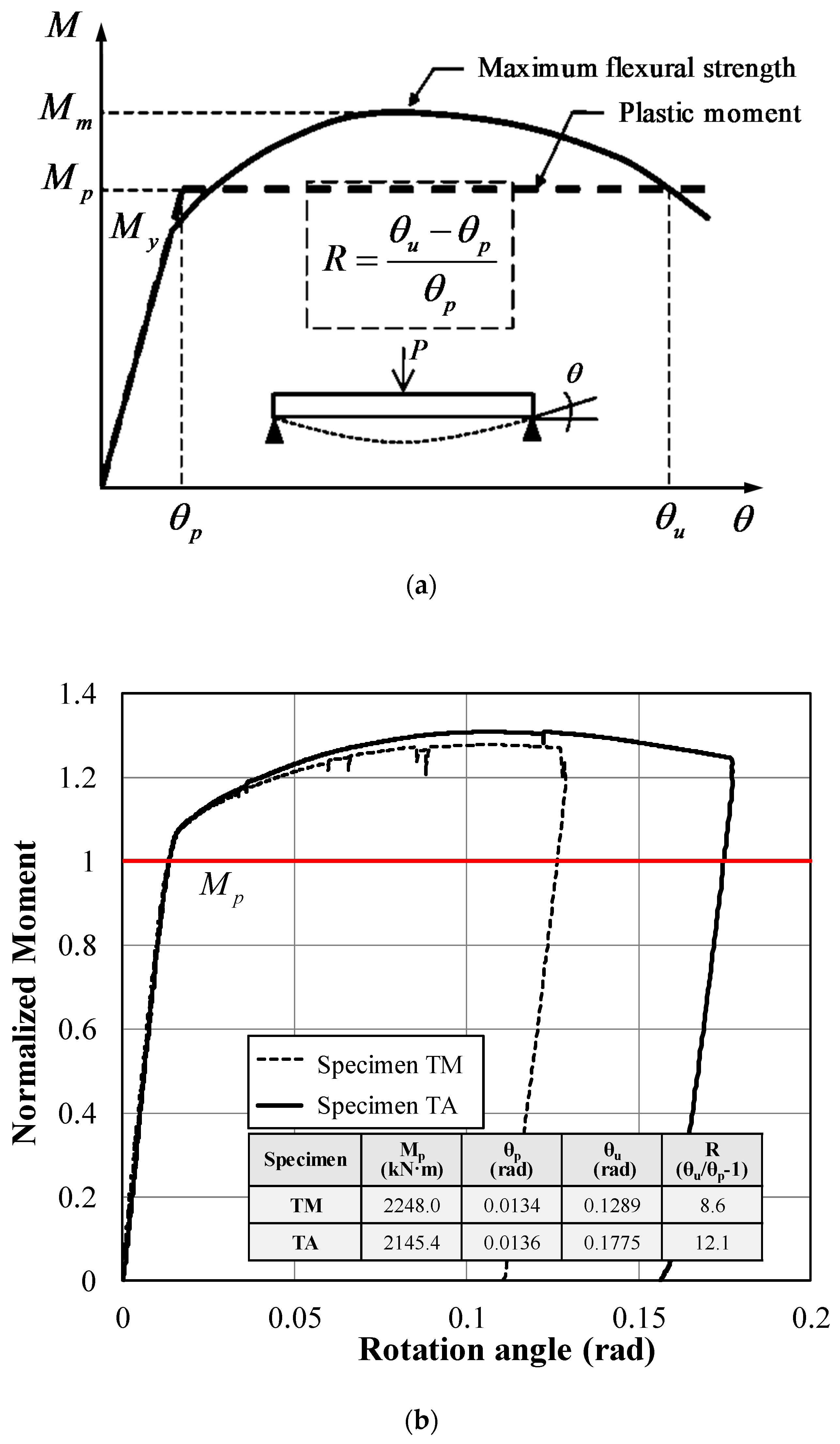
Two built-up wide flange steel beam specimens were fabricated and tested to identify the structural performances of a hybrid BWS member with the simplified welding details, and their dimensional details are shown in Figure 7. TM specimen is a typical built-up member made of SM490TMC for its web and flanges, whereas TA specimen is a hybrid BWS member whose all the dimensions and properties are identical with those of the TM specimen, except that its web plate was replaced with SM490A from SM490TMC. The section size of all the test specimens was built-up W-500 × 300 × 20 × 30. The length of the specimens was 4200 mm, and the net span length was 4000 mm between supports. The web plate was reinforced with stiffeners at the loading point. According to AISC [24] and KBC 2016 [25], the stiffeners provided at the loading point was terminated not less than four times nor more than six times the web thickness from the toe to the web-to-flange welding region. The stiffeners were welded to the top flange and web plate at a distance of 120 mm from bottom flange, as shown in Figure 8. A single point loading was applied with a simply supported condition using 3000 kN capacity UTM, and the load-displacement responses of the test specimens were measured by using the load cell equipped in the UTM and LVDTs, respectively.

4.2. Test Results

Figure 9 shows the load-displacement responses of the test specimens. For the TM specimen, which is the typical BWS beam member with the uniform material property, typical flexural behaviors were observed. The TM specimen was yielded at 2153.7 kN, and its maximum load was 2871.6 kN with the initial flexural stiffness of 148.95 kN/mm. The TA specimen with hybrid built-up section, in which SM490A was used in the web plate instead of SM490TMC, was yielded at 2107.6 kN, and the maximum load was measured at 2810.1 kN with the initial stiffness of 123.82 kN/mm. These two specimens showed almost the same flexural performances, and their failures were triggered by the local bucking of the top flange at the loading point. The yield strength of the TA specimen was somewhat lower than that of the TM specimen, which are attributed to the lower yield strength of SM490A than that of SM490TMCP, as shown in Figure 3. On the other hand, much higher deformation capacity was observed in TA specimen rather than that of TM specimen. This because the stress–strain curves of SM490A possessed longer stress hardening and post-peak regimes compared to SM490TMC, as shown in Figure 3b,c.
According to the research devoted to the quantification of flexural performance [26,27,28], the rotation capacity is an important factor to estimate the flexural performance of a beam member. Figure 10a presents how the rotational capacity of a flexural member ( θ R ) is defined in this study [24,25,29]. The inelastic rotation capacity is an important factor in evaluating the flexural performance of a steel beam, and it can be calculated, as follows:
θ R = θ u θ p θ p
where θ p is the rotation at the plastic bending moment ( M P ) and θ u is the rotation at M P after the maximum load ( M max ). The rotational capacity ( θ R ) should be more than 3.0 for the compact section (C section), which is used in the plastic design allowing the moment redistribution, and it should be more than 7.0 for the seismically compact section (SC section), which usually requires the high level of ductility, such as the special moment frame in ASCE/SEI 7-16 [30]. To evaluate the ductility of the test specimens, the measured flexural behaviors were expressed by using the normalized moment-rotation angle, as shown in Figure 10b. For a comparison purpose, the rotation angle of the test results ( θ t e s t ) can be reversely estimated by using the relation between the vertical deflection and rotational angle of an elastic beam (i.e., δ = P L 3 / 48 E I ), as follows:
θ t e s t = P L 2 16 E I = δ 2 L
where P is the external point load, L is the net span length, E is the modulus of elasticity of steel materials, I is the moment of inertia of gross section, and δ is the measured vertical deflection at the mid-span. The vertical axis presented in Figure 10b is the normalized moment, which is the measured moment divided the plastic moment capacity calculated based on the actual dimensional and material properties ( M t e s t / M p ). As shown in Figure 10b, and the inelastic rotation capacity ( θ R ) of the TA specimen was estimated at 12.1, while the TM specimen showed smaller inelastic rotation capacity ( θ R = 8.6 ) compared to that of the TA specimen. Both the specimens provided the superior ductility in order to be suitable for the seismically compact section.

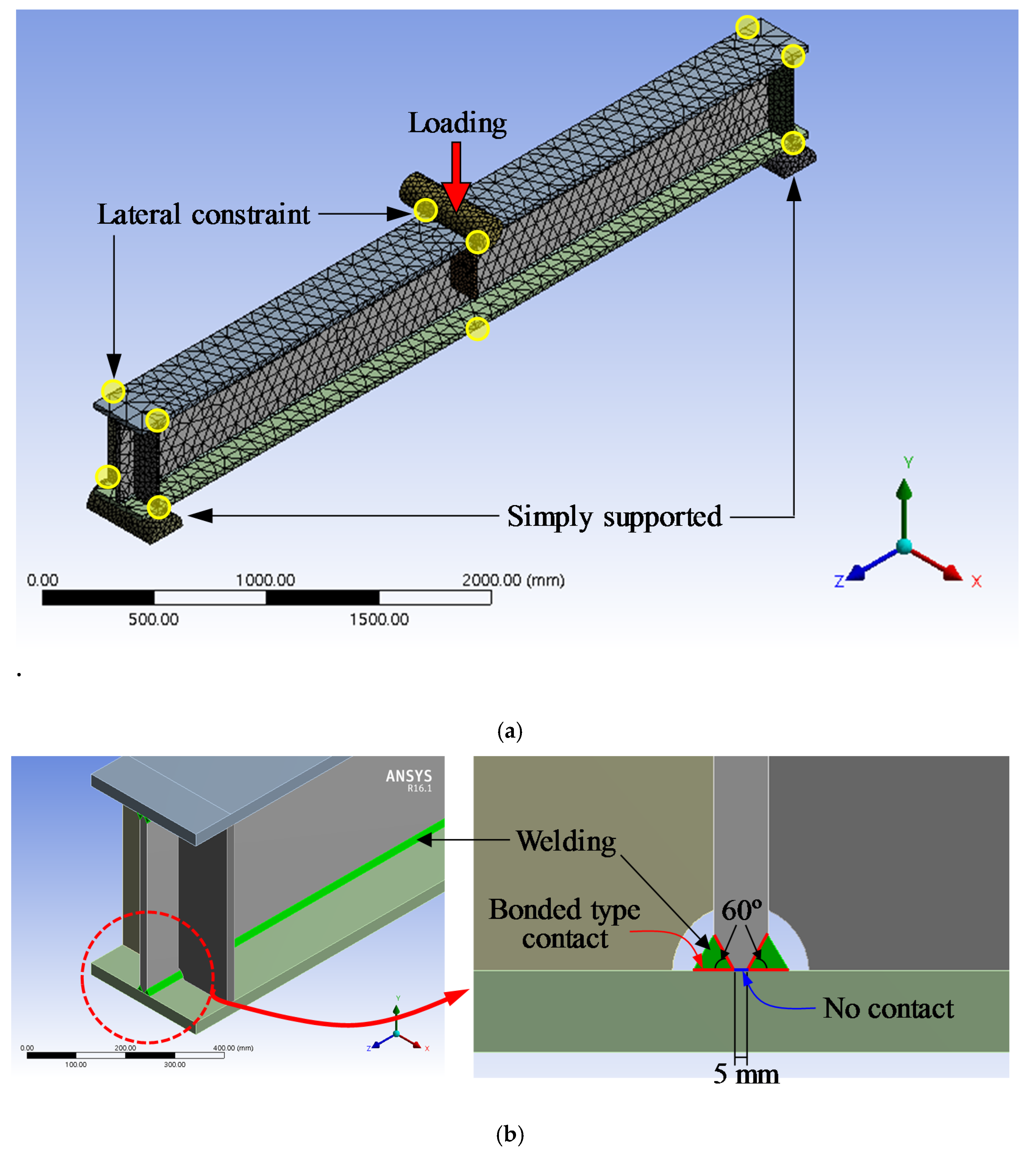
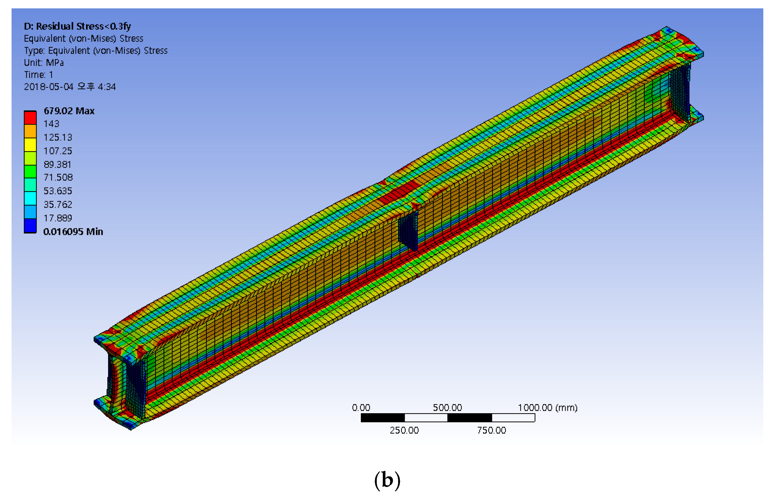
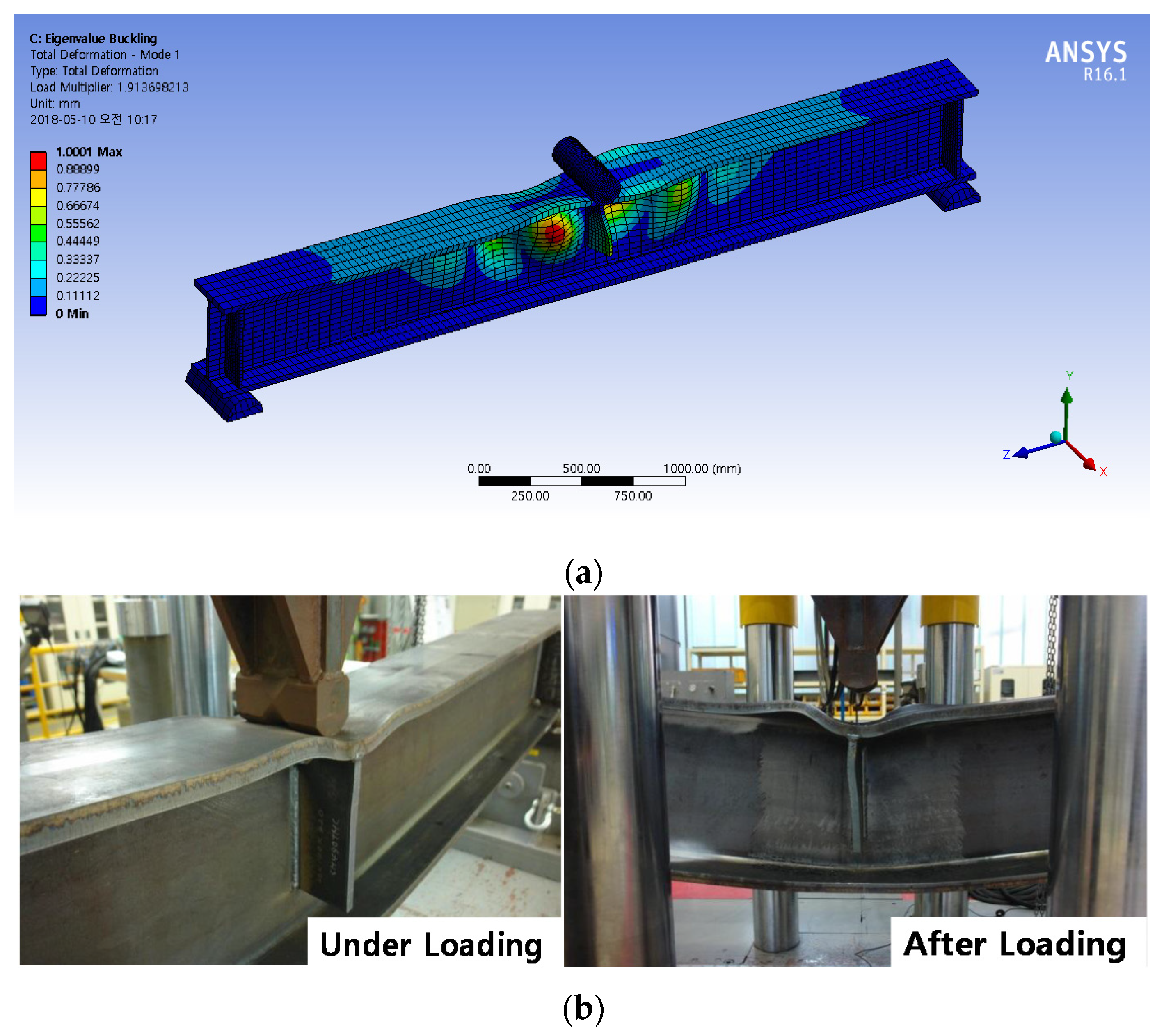
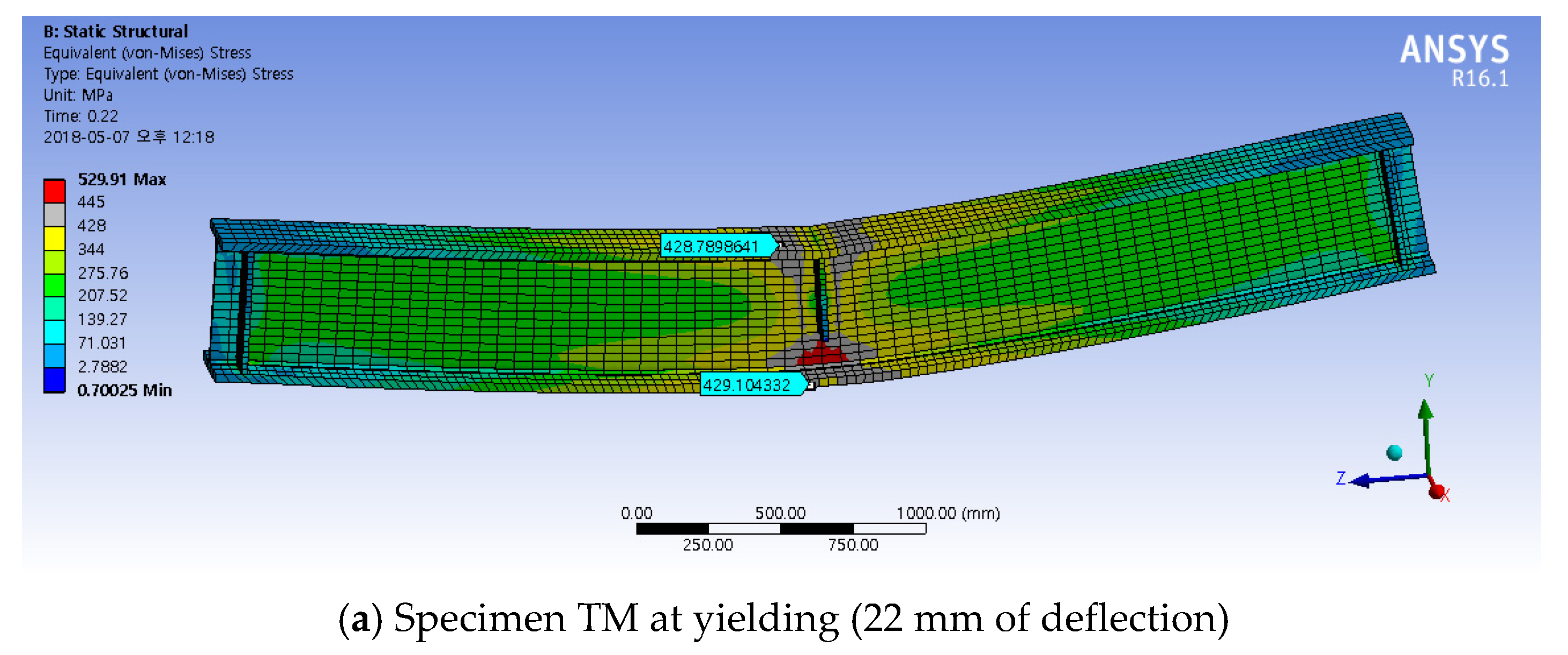
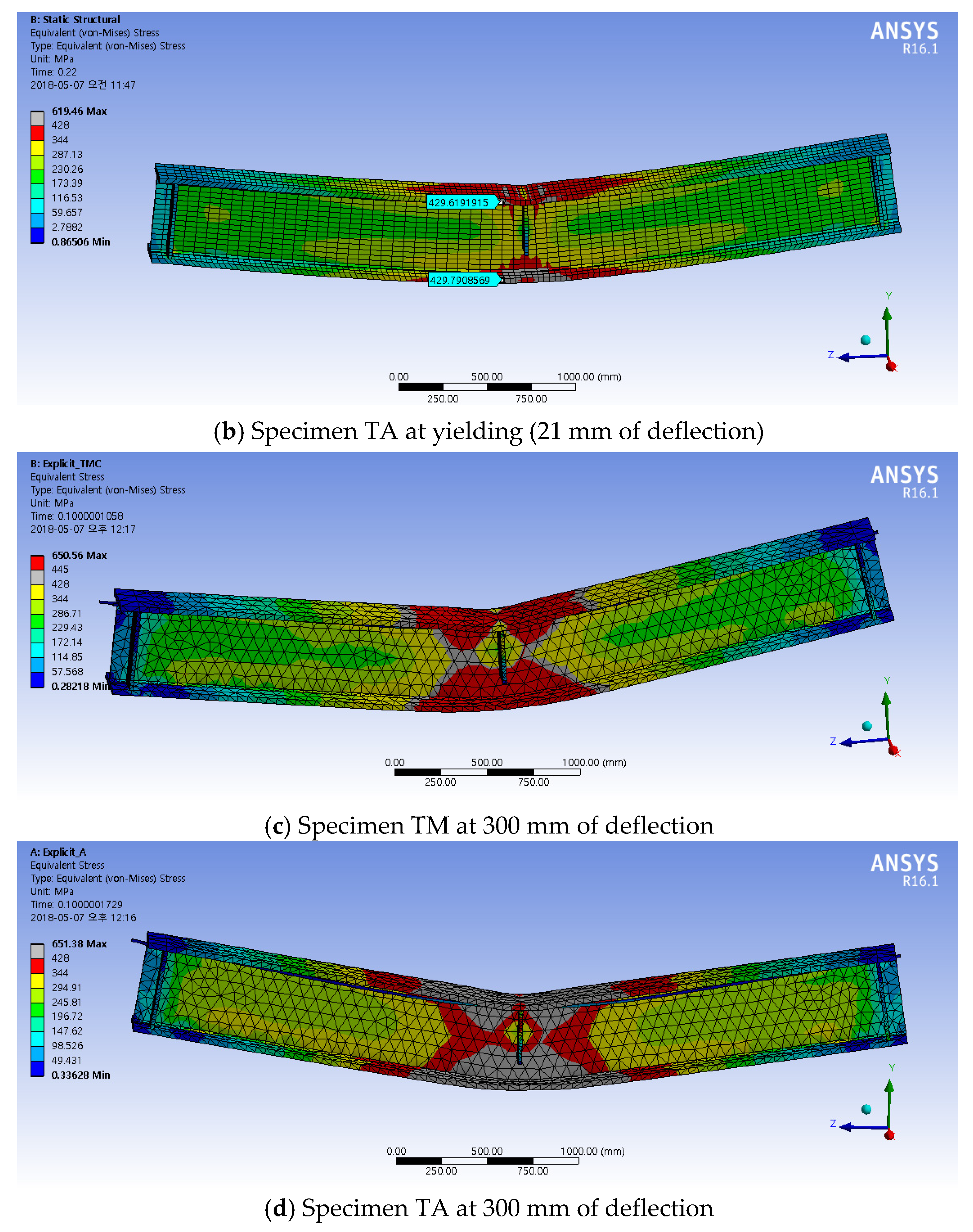
5. Finite Element Analysis

Finite element analyses were conducted to investigate the detailed flexural response of the hybrid BWS beam specimen tested in this study. The ANSYS workbench [31], a commercial platform for a finite element analysis, was used, and static and explicit dynamic analyses were performed. The analytical model considered the geometric and material nonlinearity [32], and the heat transfer analysis was also carried out, then those results were linked to consequent structural analysis to consider the effect of residual stresses at the welding connection due to restrained thermal deformations [33]. The loading and boundary conditions are presented in Figure 11a, and the flanges, web and stiffeners were modeled using 3D solid element. The beam specimens were designed with stiffeners according to the AISC specification, and those showed stable flexural behaviors without any sign of lateral-torsional buckling. Thus, the analysis was conducted with a model where the lateral constraint is assigned to exclude unexpected buckling behavior in the analysis. To determine the proper mesh size, mesh sensitivity should be considered. In this study, the size of the mesh was determined as 20 mm based on several analyses with various element sizes, and the same mesh size was applied to loading and support parts as well, which generated a total of 7499 hexahedral 3D solid elements. However, for the explicit dynamic analysis, a tetrahedral 3D solid element with an auto meshing method, in which the maximum size of the mesh was 100 mm, was applied to make the analysis optimized considering the time-dependent characteristic of the analysis. The boundaries followed the simply supported conditions. The root face ( f ) at welding connection was applied to be 6.6 mm (f = 1/3T), and the weld metals was separately modeled to consider the residual stress induced by welding, as shown in Figure 11b. In addition, the contact surfaces between beam plates and weld metal were assigned to be perfectly bonded, and no contact condition was imposed at the root face between the web and flanges. In this study, it was assumed that the magnitude of the maximum residual stress is no greater than 30% of the yield strength ( 0.3 F y ), which is the allowable residual stress specified in the structural design code [25]. To address this residual stress level in analysis, several calibrations were conducted in an iterative manner. On this basis, a thermal load of 250 °C was applied to the weld metal elements by using body temperature option provided in the software as shown in Figure 12a. Figure 12b shows the distribution of the residual stress due to restrained thermal deformation, and it was well aligned with the typical residual stress distribution. The subsequent structural analyses were carried out on which the BWS members subjected to the residual stress. Additionally, the eigenvalue analyses were also conducted to identify a buckling failure mode [34], and it clearly showed that the local buckling occurred at the top flange nearby the loading point, as depicted in Figure 13a, and this buckling pattern was quite similar to that observed from the test specimens shown in Figure 13b. Figure 14 shows the comparison between the load-displacement curves of the test specimens and those estimated from the analyses. The analysis results showed a quite good agreement with the test results; however, the flexural behaviors in the post-peak regime cannot be captured due to a limitation inherent in the stress–strain curve provided in the material library for the static analysis in the software. To identify flexural behavior after maximum load considering excessive deformation, the explicit dynamics analysis was also conducted up to the vertical displacement of 300 mm. The analysis results showed a more ductile behavior compared to the test results. The initial stiffness and maximum load estimated from the static and explicit dynamic analyses were quite well agreed with the experimental results, but both the analyses provided the flexural strength larger than the actual plastic bending moment ( M p ) of the test specimens.
Figure 15 shows the stress distributions of the specimens estimated at the yielding and maximum displacements. In the specimens, the local buckling occurred at the top flange of the loading point after yielding [1], and the specimen showed stable behavior with sufficient reserved strength while a small part of welding connection yielded. In particular, although the yield strength of web plate used in each specimen is different, the stress distributions in two specimens were quite similar. But the flange area, where yield stress is reached, were larger in the TM specimen. In addition, at the displacement of 300 mm, the much larger area was yielded in the TA specimen with SM490A compared to that of the TM specimen as presented in Figure 15c,d. However, the ultimate strengths were similar each other.
From the nonlinear finite element analysis of BWS member, it was clearly confirmed that the specimens experience yielding only at a small part of welding connection, without material failure or excessive deformation, and there is almost no difference in terms of the flexural performance between two specimens. In other words, the specimens showed sufficient flexural strength over 1.2 times the theoretical plastic bending moment, which means the specimens can be used as the special moment frame. Therefore, the built-up member replacing SM490TMCT with SM490A for web plate can be considered as a viable option.

6. Conclusions

In this study, the applicability of hybrid steel section was investigated, in which the simplified welding detail was also introduced to enhance the economic feasibility of built-up wide-flange steel members. Based on the experimental and analytical investigations, the following conclusions can be drawn:
  • The direct tensile tests for the split T specimens showed that the deformation at the welding connection was marginal, and no clear difference between the tensile performances of the welded connection and the control coupon specimen with no welding was observed.
  • The Charpy impact test showed that the toughness of SM290A is comparable with that of the high-performance TMCP steel, and it indicates that the SM490A steel can be used as the web plate of the built-up steel beams with the hybrid wide flange section.
  • It was confirmed from the flexural tests that the built-up steel beams can provide sufficient rotational capacities larger than R = 7, which is the required capacity for the seismic design, regardless of the web plate grades.
  • Both of the built-up specimens with conventional and hybrid wide flange sections showed no clear difference in the overall flexural behavior, thus it can be concluded that the built-up member with SM490TMCT instead of SM490A for web plate is applicable in practice.

Author Contributions

Original draft manuscript, H.J.; validation and data curation, S.-J.L. and S.-M.C.; investigation, J.R.K.; supervision and review writing, D.L. All authors have read and agreed to the published version of the manuscript.

Acknowledgments

This paper work was financially supported by Ministry of the Interior and Safety as Human Resource Development Project in Disaster Management.

Conflicts of Interest

The authors declare no conflicts of interest.

References

  1. Kim, K.S.; Lee, D.H.; Choi, S.M.; Choi, Y.H.; Jung, S.H. Flexural Behavior of Prestressed Composite Beams with Corrugated Web: Part 1. Development and Analysis. Compos. Part B 2011, 42, 1603–1616. [Google Scholar] [CrossRef]
  2. Brickstad, B.; Josefson, B.L. A Parametric Study of Residual Stresses in Multi-Pass Butt-Welded Stainless Steel Pipes. Int. J. Press. Vessel. Pip. 1998, 75, 11–25. [Google Scholar] [CrossRef]
  3. Jun, S.C.; Lee, C.H.; Han, K.H.; Kim, J.W. Flexural Behavior of High-Strength Steel Hybrid Composite Beams. J. Constr. Steel Res. 2018, 149, 269–281. [Google Scholar] [CrossRef]
  4. Ke, K.; Yam, M.C.H. A Performance-Based Damage-Control Design Procedure of Hybrid Steel MRFs with EDBs. J. Constr. Steel Res. 2018, 143, 46–61. [Google Scholar] [CrossRef]
  5. Smith, D.J.; Bouchard, P.J.; George, D. Measurement and Prediction of Residual Stresses in Thick-Section Steel Welds. J. Strain Anal. 2000, 35, 287–305. [Google Scholar] [CrossRef]
  6. Sawab, J.; Luu, C.H.; Nie, X.; Lim, I.; Mo, Y.L.; Li, M. Structural Integrity of Steel Plate Ultra High-Performance Concrete Modulus. J. Struct. Integr. Maint. 2016, 1, 95–106. [Google Scholar]
  7. American Institute of Steel Construction, Load and Resistance Factor Design. Specification for Structural Steel Buildings; AISC: Chicago, IL, USA, 2005. [Google Scholar]
  8. Research Institute of Industrial Science and Technology. Structural Steel for Building Construction; RIST: Incheon, Korea, 2009. [Google Scholar]
  9. Cotterell, B. Fracture Toughness and the Charpy V-notch Impact Test. Br. Weld. J. 1962, 9, 83. [Google Scholar]
  10. Kobayashi, T. Analysis of Impact Properties of A533 Steel for Nuclear Reactor Pressure Vessel by Instrumented Charpy Test. Eng. Fract. Mech. 1984, 19, 49–65. [Google Scholar] [CrossRef]
  11. Korean Standards Information Center. KS D 3861: Rolled Steels for Building Structure; Korean Standars Information Center: Seoul, Korea, 2016. [Google Scholar]
  12. Li, Y.; Song, R.; Van de Lindt, J.W. Collapse Fragility of Steel Structures Subjected to Earthquake Mainshock-Aftershock Sequences. J. Struct. Eng. 2014, 140, 04014095. [Google Scholar] [CrossRef]
  13. An, G.B.; Woo, W. Brittle crack-arrest fracture toughness in a high heat-input thick steel weld. Int. J. Fract. 2014, 185, 179–185. [Google Scholar] [CrossRef]
  14. Lee, C.H.; Han, K.H.; Uang, C.M.; Kim, D.K.; Park, C.H.; Kim, J.H. Flexural strength and rotation capacity of I-shaped beams fabricated from 800 MPa steel. J. Struct. Eng. 2012, 139, 1043–1058. [Google Scholar] [CrossRef]
  15. Prter, D.; Laukkanen, A.; Nevasmaa, P.; Rahka, K.; Wallin, K. Performance of TMCP steel with respect to mechanical properties after cold forming and post-forming heat treatment. Int. J. Press. Vessel. Pip. 2004, 81, 867–877. [Google Scholar] [CrossRef]
  16. Chang, K.H.; Jang, G.C.; Park, C.M.; Gil, H.B. Strain-rate dependence of mechanical behavior and hysteretic characteristics of TMCP steel (SM570-TMC) and its modeling. Comput. Mater. Sci. 2009, 43, 669–673. [Google Scholar] [CrossRef]
  17. American Welding Society (AWS). AWS D1.1/D1.1M-2010: Structural Welding Code-Steel; AWS: Miami, FL, USA, 2010. [Google Scholar]
  18. ASTM E 8. Standard Methods for Tension Testing of Metallic Materials; ASTM International: West Conshohocken, PA, USA, 2016. [Google Scholar]
  19. Korean Standards Information Center. KS B 0801: Test Pieces for Tensile Test for Metallic Materials; Korean Standars Information Center: Seoul, Korea, 2017. [Google Scholar]
  20. Shin, Y.T.; Kang, S.W.; Lee, H.W. Fracture characteristics of TMCP and QT steel weldments with respect to crack length. Mater. Sci. Eng. A 2006, 434, 365–371. [Google Scholar] [CrossRef]
  21. Korean Standards Information Center. KS B 0809: Impact Test Pieces for Metallic Materials; Korean Standars Information Center: Seoul, Korea, 2016. [Google Scholar]
  22. ASTM E 23. Standard Methods for Notched Bar Impact Testing of Metallic Materials; ASTM International: West Conshohocken, PA, USA, 2018. [Google Scholar]
  23. Korean Standards Information Center. KS B 0810: Method of Impact Test for Metallic Materials; Korean Standars Information Center: Seoul, Korea, 2013. [Google Scholar]
  24. AISC. Seismic Provisions for Structural Steel Buildings; American Institute of Steel Construction Ins.: Chicago, IL, USA, 2016. [Google Scholar]
  25. Architectural Institute of Korea (AIK). Korean Building Code and Commentary; Kimoondang: Seoul, Korea, 2016. [Google Scholar]
  26. D’Aniello, M.; Landolfo, R.; Piluso, V.; Rizzano, G. Ultimate Behaviour of Steel Beams under Non-Uniform Bending. J. Constr. Steel Res. 2012, 78, 144–158. [Google Scholar] [CrossRef]
  27. Güneyisi, E.M.; D’Aniello, M.; Landolfo, R.; Mermerdaş, K. A novel formulation of the flexural overstrength factor for steel beams. J. Constr. Steel Res. 2013, 90, 60–71. [Google Scholar] [CrossRef]
  28. Güneyisi, E.M.; D’Aniello, M.; Landolfo, R.; Mermerdaş, K. Prediction of the flexural overstrength factor for steel beams using artificial neural network. Steel Compos. Struct. 2014, 17, 215–236. [Google Scholar] [CrossRef]
  29. AISC-LRFD. Load and Resistance Factor Design Specification for Structural Steel Buildings; AISC: Chicago, IL, USA, 1999. [Google Scholar]
  30. ASCE. Minimum Design Loads and Associated Criteria for Buildings and Other Structures; (ASCE/SEI 7-16); American Society of Civil Engineers: Reston, VA, USA, 2016. [Google Scholar]
  31. ANSYS. Release 16 Documentation for Ansys; SAS IP, Inc.: Canonsburg, PA, USA, 2015. [Google Scholar]
  32. James, M.; Sause, R.; Green, P.S. High-strength steel: Implications of material and geometric characteristics on inelastic flexural behavior. Eng. Struct. 1998, 20, 323–335. [Google Scholar]
  33. Chang, K.H.; Lee, C.H.; Park, K.T.; Um, T.H. Experimental and Numerical Investigations on Residual Stresses in a Multi-Pass Butt-Welded High Strength SM570-TMCP Steel Plate. Int. J. Steel Struct. 2011, 11, 315. [Google Scholar] [CrossRef]
  34. Broderick, B.M.; Hunt, A.; Goggins, J.; Salawdeh, S. Recommendations for Numberical Modelling of Concentrically Braced Steel Frames with Gusset Plate Connections Subjected to Earthquake Ground Motion. J. Struct. Integr. Maint. 2017, 2, 168–180. [Google Scholar]
Figure 1. Section of built-up wide flange steel beam. (a) Typical type; (b) proposed type.
Metals 10 00567 g001
Figure 2. Simplified welding detail.
Metals 10 00567 g002
Figure 3. Tensile test result (a) SM490TMC-30T (30 mm thk.); (b) SM490TMC-20T (20 mm thk.); (c) SM490A-20T (20 mm thk.).
Metals 10 00567 g003
Figure 4. Specimens for direct tensile test at welding joint. (a) SM490TMC-30T and SM490TMC-20T; (b) SM490TMC-30T and SM490A-20T.
Metals 10 00567 g004
Figure 5. Specimens for direct tensile test at welding joint.
Metals 10 00567 g005
Figure 6. Result of direct tensile test at welding joint. (a) SM490TMC-30T and SM490TMC-20T; (b) SM490TMC-30T and SM490A-20T.
Metals 10 00567 g006
Figure 7. Charpy impact test specimen.
Metals 10 00567 g007
Figure 8. Flexural specimen detail. (a) Specimen TM (SM490TCM for web); (b) specimen TA (SM490A for web).
Metals 10 00567 g008
Figure 9. Load–deflection curves of specimens. Specimen TM: SM490TCM for web; specimen TA: SM490A for web.
Metals 10 00567 g009
Figure 10. Estimation of rotational capacity. (a) Rotational capacity of flexural member; (b) normalized moment-rotation angle curve.
Metals 10 00567 g010
Figure 11. Finite element modelling. (a) Boundary condition; (b) welding part.
Metals 10 00567 g011
Figure 12. Thermal analysis result. (a) Temperature distribution; (b) equivalent stress distribution.
Metals 10 00567 g012aMetals 10 00567 g012b
Figure 13. Buckling mode. (a) Analysis; (b) experimental specimen.
Metals 10 00567 g013
Figure 14. Flexural behavior of analysis result.
Metals 10 00567 g014
Figure 15. Stress distribution of analysis results.
Metals 10 00567 g015aMetals 10 00567 g015b
Table 1. Properties of grade 490 steels.
TypeYield Stress
(MPa)
Tensile Stress
(MPa)
Elongation
(%)
Charpy Absorption Energy
(J/mm2)
Note
(%)
Lower LimitLower LimitUpper LimitLower LimitLower Limit* Upper Limit
SM490
(carbon Content)
A (0.20)29549061023-C: 0.22
B (0.18)27C: 0.20
C (0.18) 47-
Y32521--
SM490
TMC
3254906102327CeqL: 0.38
CeqU: 0.40
PU: 0.26
PL: 0.27
* C: Carbon content; CeqL: Carbon equivalent (less than 50 mm); CeqU: Carbon equivalent (more than 50 mm); PU: Parameter of weld crack susceptibility of base metal (less than 50 mm); and CL: Parameter of weld crack susceptibility of base metal (more than 50 mm).
Table 2. Tensile test result.
TypeYield Strength
(MPa)
Tensile Strength,
(MPa)
Yield Ratio
(%)
Elongation
(%)
SM490TMC 30T
(30 mm thk.)
142253479.031.5
242853380.032.4
343353680.932.0
average42853480..031.9
SM490TMC 20T
(20 mm thk.)
144652884.529.5
244052683.629.5
344953484.129.5
average44552984.129.5
SM490A 20T
(20 mm thk.)
134554363.631.8
233553063.332.2
335254264.932.0
average34453864.032.0
Table 3. Charpy impact test result.
TypeTest Result
(J)
SM490A 20T
(20 mm thk.)
164
260
356
458
557
average59.0
SM490TMC 30T
(30 mm thk.)
1250
2263
3255
4271
5275
average262.8
SM490TMC 20T
(20 mm thk.)
1222
2234
3232
4225
5225
average227.6
Temperature condition: 0 ± 1 °C, test method: KS B 0810.

