Abstract
The objective of the present study was to estimate the influence of laser shock peening on the fatigue properties of AA2024-T3 specimens with a fastener hole and to investigate the possibility to heal the initial cracks in such specimens. Fatigue cracks of different lengths were introduced in the specimens with a fastener hole before applying laser shock peening. Deep compressive residual stresses, characterized by the hole drilling method, were generated into the specimens by applying laser shock peening on both sides. Subsequently, the specimens were subjected to fatigue tests. The results show that laser shock peening has a positive effect regarding the fatigue life improvement in the specimens with a fastener hole. In addition, laser shock peening leads to a healing effect on fatigue cracks. The efficiency of this effect depends on the initial crack length. The effect of laser shock peening on the fatigue life periods was determined by using resonant frequency graphs.
1. Introduction
Riveting is the most common method to join structural elements in the aircraft industry [1]. This is attributed to numerous practical advantages such as the relatively low cost, applicability of automatic assembly operations, and possibility of joining dissimilar materials. However, riveted and bolted joints have some disadvantages: rivets add weight to the structure, parts cannot be disassembled without destroying the rivet, and riveted joints are prone to fatigue failure. The fatigue behavior of riveted joints was explicitly investigated in previous studies. The mechanism of fatigue crack initiation and the configuration of the crack depend on various factors, e.g., rivet type, squeeze force, sheet thickness, etc. [2]. However, one of the major factors controlling the fatigue properties of a riveted joint is the stress concentration of the hole itself. Due to stress concentration at the rivet holes, fatigue cracks mainly nucleate at or close to rivet holes. This phenomenon was well described by Schijve [3]. Since the fatigue of aircraft structures is extremely important for ensuring the safety of the aircraft, different techniques were developed to improve the fatigue behavior of fastened joints. Skorupa et al. [4] studied the influence of interference fitting on fatigue behavior of rivet holes in AA2024-T3, and it was established that for axial loading with increasing the squeeze force, the fatigue life extends. Currently, one established technique is cold expansion. This technique utilizes the introduction of residual stresses around the hole. These compressive residual stresses lead to fatigue crack growth retardation under cyclic loading, improving the fatigue resistance. Fu et al. [5] investigated various approaches of cold expansion, and it was established that the fatigue life of AA7050 can be increased by a factor of six using cold expansion. Yongshou et al. [6] investigated the residual stress field around the expanded hole and fatigue properties of the aluminum alloy LY12-CZ with various interference values (interference value describes how much a mandrel radius is larger than a hole radius), and it was shown that with increasing interference value from 0% to 6%, the fatigue life increases by a factor of six.
Another promising way to improve the behavior of fatigue critical components is laser shock peening (LSP) [7]. LSP is a process in which under the influence of laser pulses, mechanical shock waves arise, propagating under the surface of the material [8]. When the peak pressure of waves exceeds the Hugoniot elastic limit (HEL) of the material, plastic deformation occurs, which leads to compressive residual stresses within the material, i.e., near the surface. The subsurface compressive residual stresses are balanced by the stress field within the material or in zones adjacent to the LSP-treated area. In recent years, various studies have been conducted on the effect of LSP on the fatigue properties of different metallic alloys. Ivetic et al. [9] investigated the effect of the sequence of processes (hole introduction and LSP) on the fatigue properties of AA6082-T6 specimens. The experiments showed that the sequence of processes is important for the improvement of the fatigue life. The beneficial effect of LSP is higher if the hole is introduced after LSP. This is linked to the fact that compressive residual stresses in LSP-treated specimen are compensated by tensile residual stresses [3], and in the case of applying LSP after drilling a hole, the magnitude of tensile stresses would be higher, which would lead to a shorter fatigue life. Achintha et al. [10] evaluated the effect of the size of the LSP-treated area on fatigue properties of AA2024-T3 specimens. Two cases were considered: (i) LSP was performed just around the hole, and (ii) LSP was applied across the entire width of the specimen. The results showed that specimens with a smaller treated area around the hole can withstand more loading cycles than specimens peened along the entire width. Jiang et al. [11] considered the effect of the laser radiation power density on the distribution of residual stresses through the specimen thickness and on the fatigue life of AA7050-T7451 specimens. The results showed that with an increase of the laser power density, the fatigue life of specimens tends to increase. Various power densities lead to different types of residual stress distribution, crack initiation regions, and crack growth directions. The crack growth rate in the LSP-treated field also depends on the pulse power density. Chupakhin et al. [12] investigated the effect of pulse energy and number of treatment overlaps. The experiments were conducted on AA2024-T3 specimens with 2 mm thickness. The study showed that the determining factor is the total amount of energy applied to the specimens, but not the laser power density or number of overlaps alone. Fomin et al. [13] studied the effect of LSP on the fatigue properties of laser beam-welded Ti-6Al-4V butt joints. It was observed that LSP mainly affects surface defects rather than internal defects. Another study regarding laser beam welding was performed on AA6056 [14]. The authors studied the effect of LSP on pre-cracked laser beam-welded specimens (crack depth is approximately 1.2 mm), and it was established that LSP allows recovering the fatigue life of specimens with surface fatigue cracks to as-welded condition (without surface fatigue cracks). Kashaev et al. [15] investigated the effect of LSP on the fatigue crack propagation behavior of AA2024-T3 specimens with 2 mm thickness. It was shown that applying LSP can significantly reduce fatigue crack propagation, and the higher the laser energy or the number of overlaps, the stronger the retardation effect. Liu et al. [16] studied the possibility of treating fatigue cracks in a polycrystalline copper film. As a result of the fatigue test, it was found that applying LSP to damaged specimen is more advantageous than applying LSP to undamaged specimen in terms of fatigue life extension. These results suggest that the healing of fatigue cracks is possible for different metallic materials. Busse et al. [17] reported the effect of LSP on riveted lap joints. The authors used different strategies, i.e., process parameters and areas of applying LSP to the specimens. Every chosen strategy showed that LSP increased the fatigue life of riveted joints but to varying degrees. Overall, it can be summarized that the laser parameters, size, and form of the treated area are crucial for improving the fatigue properties.
This study addresses two objectives. The first one was to estimate the influence of LSP on fatigue crack initiating and propagation in specimens with a fastener hole. The second one was to investigate the possibility of healing already existing cracks in specimens with a fastener hole using LSP.
2. Materials and Methods
2.1. Material and Specimens
AA2024-T3 is one of the most widely used aluminum alloys in the aircraft industry [18]. AA2024-T3 refers to an aluminum alloy of the Al-Cu-Mg system alloyed with manganese.
Figure 1 shows the geometry of the specimens used for fatigue tests. The central hole simulates a fastener hole in a riveted/bolted joint of a fuselage structure. Its diameter of 4.8 mm corresponds to the common size of a rivet hole [19]. The thickness of the specimens is 2 mm.
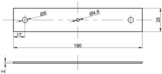
Figure 1.
Geometry of the specimens for fatigue test. All of the dimensions are in mm.
2.2. Experimental Program
To investigate the effect of LSP treatment on the fatigue behavior of the specimens with a fastener hole, five groups of the specimens were prepared. Each group contained 10 specimens, i.e., 8 specimens for primary fatigue tests and 2 for possible substitute tests. All of the specimens were tested under the same loading conditions to analyze the results using Weibull distribution.
The first group of the specimens represents the unpeened base material (BM) with a hole. The specimens of the second, third, and fourth groups were intended to assess the effect of LSP on initial fatigue cracks of different lengths. In these specimens, initial cracks were created before applying LSP but with different initial crack lengths. The initial crack length in the specimens of the second group was 1.0 ± 0.1 mm, while that in the third group was 1.8 ± 0.1 mm, and in the fourth group, it was 2.5 ± 0.1 mm. The minimum initial crack length was chosen due to the limitations of the used method to create the cracks. The maximum initial crack length of 2.5 ± 0.1 mm was chosen since larger cracks have high growth rates that are difficult to monitor precisely. The crack length was determined as the maximum crack length on the surface of the specimen on one side from the rivet hole. After creating the cracks, the specimens were treated by LSP to subsequently perform the fatigue tests.
The specimens of the fifth group were manufactured without a central hole. They are intended to study the effect of LSP on the specimens with a fastener hole in as-manufactured condition without an initial fatigue crack. According to the study of Ivetic et al. [9], it is advantageous when LSP is applied before drilling a hole. Therefore, firstly the specimens were treated by LSP, and subsequently holes were introduced in the specimens. The specifications of the used specimens are given in Table 1 and illustrated in Figure 2. Figure 3 presents the block scheme of the experimental program.

Table 1.
Specifications of the specimens used in the fatigue test.
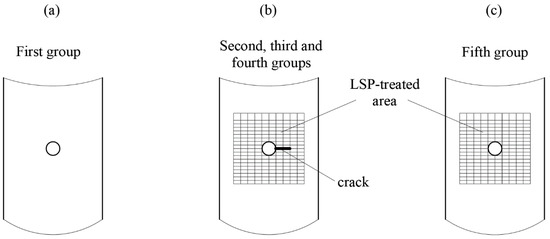
Figure 2.
(a) Illustration of the base material specimens, including a fastener hole; (b) Illustration of the specimens from the 2nd, 3rd, and 4th groups, including a fastener hole and an initial crack, which are subsequently treated by LSP; (c) Illustration of the specimens from the 5th group, where the specimens are first treated by LSP before a fastener hole is introduced.
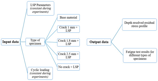
Figure 3.
Block scheme of used experimental program.
2.3. Fatigue Testing of Specimens and Preparation of Specimens with Initial Fatigue Cracks
For performing the axial fatigue tests, the Testronic 100-kN RUMUL resonant testing machine (Russenberger Prüfmaschinen AG, Neuhausen am Rheinfall, Switzerland) was used. The operating frequency of the testing machine typically ranges from 40 to 260 Hz. The frequency in case of the specimens investigated in this study was 85–90 Hz. Each specimen was tested at the same load level at room temperature: The maximum calculated stress level in the specimen cross-section without a fastener hole was 110 MPa at an applied stress ratio of 0.1.
To create the initial fatigue cracks in the specimens of groups 2, 3, and 4, the specimens were subjected to a pre-fatigue test. The used resonant testing machine allows to monitor resonant frequency during the fatigue test. The resonant frequency versus number of loading cycles record was used to identify the number of cycles required for crack initiation and crack propagation. Lorenzino and Navarro [20] reported that an initial growth of the resonant frequency can be attributed to the effect of cyclic hardening in the material, while a drop in the frequency is associated with a crack growth. Similar observations were also reported in [14]. To monitor the fatigue crack growth, a visual inspection was carried out using an optical microscope on both specimen surfaces. On the front and back surfaces of each specimen, reference marks were preliminarily applied to indicate the targeted length of the initial fatigue crack. As soon as the fatigue crack reached the reference mark, the fatigue test was stopped. By this method, specimens with initial fatigue cracks of 1.0 ± 0.1 mm, 1.8 ± 0.1 mm, and 2.5 ± 0.1 mm length were created. Figure 4 presents one specimen with a created initial fatigue crack of 2.5 ± 0.1 mm length.
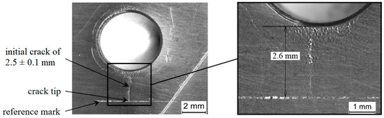
Figure 4.
Specimen with a fastener hole where the initial crack length in the hole is 2.5 ± 0.1 mm.
2.4. Laser Shock Peening and Residual Stress Analysis
The main goal of applying LSP is to introduce deep compressive residual stresses into the material up to several millimeter depth [21]. Appropriate LSP parameters were identified according to the study by Chupakhin et al. [12], in which the same material and specimen thickness were used. In the current study, the Q-switched Nd:YAG laser operating at 10 Hz was used. The wavelength was 1064 nm and the pulse duration was 20 ns (full width at half maximum, FWHM). A diffractive optical element was used to deliver 5 J to a square spot of 2.5 mm × 2.5 mm on the specimen surface. The overlap rate of the adjacent spots in the vertical direction was 50%; in horizontal direction, the overlap was not used. The treated area was 25 mm × 25 mm. The size of the LSP-treated area was chosen to cover completely the initial fatigue cracks and additionally based on the paper of Achintha et al. [10]. The authors showed that applying LSP across the entire width of a specimen is unreasonable in terms of fatigue life prolongation, because in that case, tensile residual stresses occur in the mid-plane of the specimen, and the hole would be affected by these stresses. On the other hand, if LSP is applied only around the hole, the residual tensile stresses occur near the edge of the specimen, and it becomes possible to place the entire hole into residual compression. The specimens were covered for LSP by a stainless steel foil with the thickness of 0.1 mm. The material surface was covered by a laminar water layer with a thickness between 2 and 3 mm. The specimens were LSP-treated on both sides. A photograph of the specimen after the LSP treatment is presented in Figure 5.
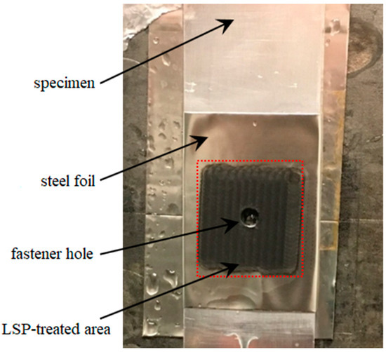
Figure 5.
A representative specimen with a fastener hole after LSP treatment.
The hole drilling system “PRISM” of Stresstech company, equipped with electronic speckle pattern interferometry (ESPI), was used to obtain depth-resolved residual stress profiles. Details regarding the hole drilling method can be found in ASTM Standard E837-08 [22].
Specimens without a fastener hole were used for residual stress analysis. These were identical in size with the specimens used in fatigue tests. The specimens were peened from both sides. Figure 6 shows a sketch of the specimen for residual stress analysis. Depth-resolved residual stress profiles were obtained from three points from both specimen sides up to a depth of 1.0 mm near the center of the specimen, i.e., within the LSP-treated area. The holes were incrementally drilled with a diameter of 2.0 mm.
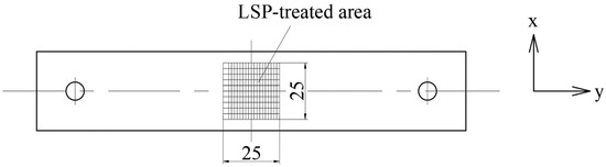
Figure 6.
Sketch of the specimen for residual stress analysis. All of the dimensions are in mm.
The results of the residual stress analysis are presented in Figure 7. Deep compressive residual stresses were introduced through the entire specimen thickness. The non-equibiaxiality in the residual stress profiles could be due to the sequence of LSP, material texture, and geometry of the analyzed specimen [23]. Near the surface, the absolute value of compressive residual stresses reaches 220 MPa, which corresponds to approximately 67% of the yield strength of AA2024-T3, i.e., 326 MPa [18]. Chupakhin et al. [24] studied the influence of elasto-viscoplastic material behavior on residual stress analysis using the hole drilling method. The error in the analysis due to plasticity is related to the ratio of maximum residual stresses to yield strength. It was shown that if residual stresses do not exceed 80% of the material yield strength, the error is negligible, and the correction is not necessary. Consequently, it is assumed that appropriate quantitative results of residual stress analysis are obtained in this study. It should be noted that the influence of the fastener hole on residual stresses is assumed to be negligible, since only small values of residual stresses are introduced via hole drilling [25].
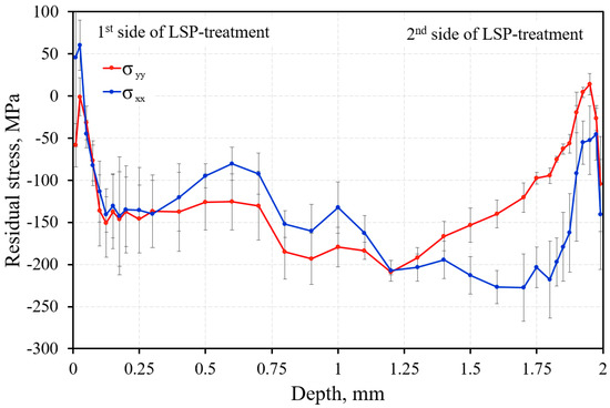
Figure 7.
Depth resolved residual stress profile in LSP-treated specimen, as shown in Figure 6.
2.5. Weibull Distribution
For analyzing the fatigue test results, the two-parameter Weibull distribution is used, which is described by:
where F(N) is the probability of failure, N is the number of cycles, T is the scale parameter, and β is the shape parameter. The shape parameter β reflects the scatter in the distribution. The value of the scale parameter T represents the cycles during which, on average, 63.2% of the observed objects are destroyed.
3. Results and Discussion
3.1. Fatigue Tests
The fatigue test results of all specimens analyzed using the Weibull distribution are shown in Figure 8. The parameters of the Weibull distribution were obtained using the least square method for each group of the specimens, which are summarized in Table 2. It can be concluded that LSP significantly increases the fatigue life of the specimens with a fastener hole. The scale parameter T is considered as characteristic life. A comparison of the first group (BM) with the fifth group (LSP + hole) shows that use of LSP increases the fatigue life by a factor of 3.1. Comparing the results to specimens with initial fatigue cracks (specimens in groups 2, 3, and 4), it was observed that LSP can be applied for the repair of initial fatigue cracks. The fatigue life of the LSP-treated specimens with the longest initial crack of 2.5 ± 0.1 mm is higher than the fatigue life of the base material specimens, i.e., by a factor of 1.5. It is comprehensible that with increasing initial crack length, the scale parameter T decreases as the life extension decreases. This suggests that the scatter of values in the distribution increases and the process becomes less predictable. It is interesting to note that the LSP-treated specimens with a 1.0-mm-long crack exhibit approximately the same fatigue properties as the specimens without an initial crack. However, one should recognize that the tested specimens had slightly different peening strategies; namely, the specimens from the fifth group (LSP + hole) were peened first and then drilled. In contrast, for the second group, the LSP processing was performed after drilling and pre-cracking.
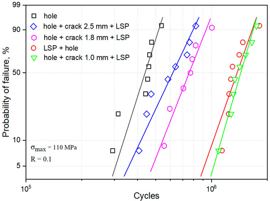
Figure 8.
Weibull plot for all groups of tested specimens.
Table 2.
Parameters of Weibull distribution for each group.
Since the obtained results show only the effect of LSP in the medium cycle fatigue regime, the question arises as to whether it is appropriate to transfer the results in the regime of high cycle fatigue. Benedetti et al. [26] established that the benefit of compressive residual stresses introduced by conventional shot peening (SP) can be lost, at least partially, moving toward the very high cycle fatigue regime. On the other hand, compressive residual stresses introduced by LSP are deeper and higher than by SP [27]. Furthermore, SP causes significant changes in microstructure [28]; however, LSP, in turn, does not lead to such changes [29]. In this regard, the detrimental effect seen for SP when moving from the medium to high cycle fatigue regime is not expected for LSP. Therefore, the positive effect of LSP, which was shown is this study, is assumed to remain the same in high cycle fatigue regime. The positive effect of LSP on the retardation of fatigue cracks in the high cycle fatigue regime was also demonstrated in a previous study of Kashaev et al. [14].
3.2. Effect of LSP on Crack Initiation and Crack Growth
As mentioned before, analyzing the behavior of the resonant frequency during the fatigue test allows the determination of a fatigue crack nucleation phase. Using this approach, it is possible to divide the fatigue life into two periods: fatigue crack initiation and fatigue crack growth. This approach was applied for the specimens of the first and fifth groups to analyze the effect of LSP on the two different periods of the fatigue life. Figure 9 presents the frequency graph for one exemplary specimen of the first and fifth group. An increase in the resonant frequency corresponds to crack initiation, while a decrease in the frequency corresponds to crack growth. In the specimen without LSP, the crack nucleated approximately at 3.33 × 10⁵ cycles, and the entire fatigue life was 4.76 × 10⁵ cycles; therefore, the crack growth period of the specimen without LSP was 1.43 × 10⁵ cycles. In case of specimen with LSP, the crack nucleated approximately at 3.75 × 10⁵ cycles, and the entire fatigue life was 1.25 × 10⁶ cycles; therefore, the crack growth period of the specimen with LSP was 8.71 × 10⁵ cycles. The crack initiation period was enhanced by a factor of 1.1 using LSP, but the crack growth period was increased by a factor of 6.1. These results clearly illustrate that the improvement of the fatigue life is achieved mainly by increasing the crack growth period.
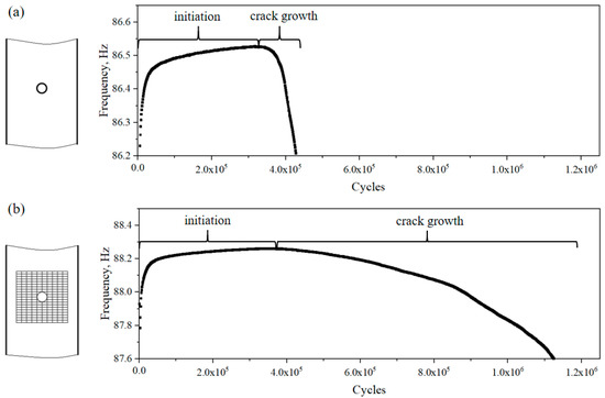
Figure 9.
(a) Frequency graph of a base material specimen with a fastener hole. (b) Frequency graph of a specimen treated first by LSP, and subsequently, a fastener hole is introduced.
Using the approach described above, the cycles required for crack initiation and crack growth for all of the specimens from the first and the fifth groups were calculated. The results are presented as a Weibull plot with two distributions for each group. The total number of cycles before failure was divided into the number of cycles to crack nucleation and the number of cycles from crack nucleation until final failure of the specimen (crack growth). The results are shown in Figure 10. The Weibull parameters for these cases are summarized in Table 3. The positive effect of LSP on the fatigue crack growth behavior is clearly visible and is significantly larger compared to the fatigue crack initiation. Enhancement of the crack initiation period is approximately 1.4, where the crack growth period is increased by a factor of 6.5. Overall, it is concluded that the positive effect of LSP on the prolongation of the fatigue crack growth period is significantly higher (approximately by a factor of 4.6) than its effect on the crack initiation period. In other words, the main mechanism of fatigue life increasing through laser shock peening is an enhancement of the fatigue crack growth period.
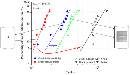
Figure 10.
Effect of LSP on the crack initiation and crack growth periods of the fatigue life. The blue line corresponds to the number of cycles for the crack nucleation in the specimens without LSP, the red line corresponds to the number of cycles for the crack growth (from nucleation until failure) in the specimens without LSP, the green line corresponds to the number of cycles for the crack nucleation in the specimens with LSP, and the black line corresponds to the number of cycles for the crack growth in the specimens with LSP. The blue arrow represents the positive effect of LSP on the fatigue behavior of the specimens regarding the fatigue crack initiation, and the red arrow represents the positive effect of LSP on the fatigue behavior of the specimens regarding the fatigue crack growth.
Table 3.
Weibull parameters for the estimation of the effect of LSP on fatigue life periods.
After establishing that LSP mainly affects the fatigue crack growth period, the fatigue growth was investigated further in two different scenarios. In the first case, the crack nucleated before applying LSP, corresponding to the 2nd, 3rd, and 4th groups. For this analysis, only the second group (hole + crack 1 mm + LSP) is analyzed. In the second case, the crack nucleated after applying LSP; this case corresponds to the fifth group (LSP + hole). To allow a direct comparison, the crack growth kinematics of 1.0-mm long cracks have been studied depending on the LSP treatment application: prior to the crack initiation (LSP as prevention) or after the crack initiation (repair). To compare these scenarios, the number of cycles until final failure was determined. A Weibull plot was used to display the results; see Figure 11. The results show that the number of cycles required to grow from a 1.0 mm crack until final failure in specimens treated by LSP after crack nucleation is significantly higher than in specimens treated by LSP before fatigue crack nucleation. Therefore, it can be concluded that the crack nucleated in the field of residual stresses grows faster than the crack nucleated without prior residual stresses. This leads to the conclusion that the LSP technology has the biggest potential to be applied as a repair technique, i.e., by introducing residual stress fields in the localized area around a fatigue crack detected during maintenance. This can increase the inspection intervals significantly, thus reducing the risk of failure and maintenance costs.
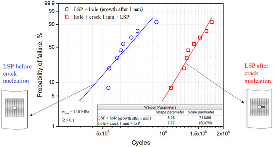
Figure 11.
Effect of LSP sequence on the crack growth behavior after 1 mm crack length.
4. Conclusions
In this study, the effect of laser shock peening on the fatigue properties of AA2024-T3 alloy was investigated. Fatigue tests were conducted on different groups of specimens: base material specimens with a fastener hole, specimens with a fastener hole and an initial crack treated subsequently by LSP, and specimens where LSP is applied first and then the fastener hole is introduced. Based on the obtained results, the following conclusions are drawn:
- The fatigue life of the specimens with a fastener hole introduced after LSP treatment is higher by a factor of 3 than that of specimens with a hole, but without LSP.
- LSP significantly extends the fatigue life of specimens with an initial fatigue crack, but the effect of LSP depends on the crack length. The larger the crack length, the weaker the effect of the subsequent LSP processing. The fatigue life of LSP-treated specimens with an initial crack of 2.5 ± 0.1 mm exceeds the fatigue life of base material specimens by a factor of 1.5, specimens with an initial crack of 1.8 ± 0.1 mm by a factor of 1.7, and specimens with an initial crack of 1.0 ± 0.1 mm by a factor of 3.3.
- In accordance with the above findings, LSP can be applied to the specimens without cracks in a fastener hole, which is in good agreement with previous studies [8,9,10,11,17], and it can be applied for healing the fatigue cracks up to a length of 2.5 ± 0.1 mm detected in a fastener hole with the diameter of 4.8 mm.
- LSP has a different effect on the fatigue initiation and growth periods. The effect of LSP on the crack growth period is significantly higher (approximately by a factor of 4.6) than on the crack initiation period. The effect of LSP on the crack retardation as a function of the crack length has been quantitatively studied.
- Cracks nucleated in residual stress fields grow significantly faster than cracks nucleated before introducing residual stresses. In this regard, LSP has good potential to be applied as a repair technique.
Author Contributions
Conceptualization, N.K. and F.F.; methodology, F.F.; investigation, R.S. and F.F.; resources, N.K.; writing—original draft preparation, R.S.; writing—review and editing, R.S., F.F., B.K., and N.K.; visualization, R.S.; supervision, F.F., B.K., and N.K. All authors have read and agreed to the published version of the manuscript.
Funding
This research received no external funding.
Acknowledgments
The authors would like to thank Falk Dorn, Kay Erdmann, Rene Dinse, Stefan Riekehr from the Helmholtz-Zentrum Geesthacht for their technical assistance and support in the experimental work.
Conflicts of Interest
The authors declare no conflict of interest.
References
- Barret, R.T. Fastener Design Manual; NASA Reference Publication 1228: Cleveland, OH, USA, 1990. [Google Scholar]
- Skorupa, A.; Skorupa, M.; Machniewicz, T.; Korbel, A. Fatigue crack location and fatigue life for riveted lap joints in aircraft fuselage. Int. J. Fatigue 2014, 58, 209–217. [Google Scholar] [CrossRef]
- Schijve, J. Fatigue of Structures and Materials; Springer: New York, NY, USA, 2009. [Google Scholar]
- Skorupa, A.; Skorupa, M.; Machniewicz, T.; Korbel, A. Fatigue strength reduction factors at rivet holes for aircraft fuselage lap joints. Int. J. Fatigue 2015, 80, 417–425. [Google Scholar] [CrossRef]
- Fu, Y.; Ge, E.; Su, H.; Xu, J.; Li, R. Cold expansion technology of connection holes in aircraft structures: A review and prospect. Chin. J. Aeronaut. 2015, 28, 961–973. [Google Scholar] [CrossRef]
- Yongshou, L.; Xiaojun, S.; Jun, L.; Zhufeng, Y. Finite element method and experimental investigation on the residual stress fields and fatigue performance of cold expansion hole. Mater. Des. 2010, 31, 1208–1215. [Google Scholar] [CrossRef]
- Ding, K.; Ye, L. Laser Shock Peening: Performance and Process Simulation; Woodhead Publishing Limited: Cambridge, UK, 2006. [Google Scholar]
- Yang, J.M.; Her, Y.C.; Han, N.; Clauer, A. Laser shock peening on fatigue behavior of 2024-T3 Al alloy with fastener holes and stopholes. Mat. Sci. Eng. A 2001, 298, 296–299. [Google Scholar] [CrossRef]
- Ivetic, G.; Meneghin, I.; Troiani, E.; Molinari, G.; Ocaña, J.L.; Morales, M.; Porro, J.A.; Lanciotti, A.; Ristori, V.; Polese, C.; et al. Fatigue in laser shock peened open-hole thin aluminium specimens. Mat. Sci. Eng. A 2012, 534, 573–579. [Google Scholar] [CrossRef]
- Achintha, M.; Nowell, D.; Furfari, D.; Sackett, E.E.; Bache, M.R. Fatigue behavior of geometric features subjected to laser shock peening: Experiments and modeling. Int. J. Fatigue 2014, 62, 171–179. [Google Scholar] [CrossRef]
- Jiang, Y.F.; Ji, B.; Gan, X.D.; Hua, C.; Li, X.; Zhu, H. Study on the effect of laser peening with different power densities on fatigue life of fastener hole. Opt. Laser Technol. 2018, 106, 311–320. [Google Scholar] [CrossRef]
- Chupakhin, S.; Klusemann, B.; Huber, N.; Kashaev, N. Application of design of experiments for laser shock peening process optimization. Int. J. Adv. Manuf. Tech. 2019, 102, 1567–1581. [Google Scholar] [CrossRef]
- Fomin, F.; Klusemann, B.; Kashaev, N. Surface modification methods for fatigue properties improvement of laser-beam-welded Ti-6Al-4V butt joints. Procedia Struct. Integr. 2018, 13, 273–278. [Google Scholar] [CrossRef]
- Kashaev, N.; Ushmaev, D.; Ventzke, V.; Klusemann, B.; Fomin, F. On the application of laser shock peening for retardation of surface fatigue cracks in laser beam welded AA6056. Fatigue Fract. Eng. Mater. Struct. 2020; in press. [Google Scholar] [CrossRef]
- Kashaev, N.; Chupakhin, S.; Ventzke, V.; Hortsmann, M.; Riekehr, S.; Barabini, A.; dos Santos, J.F.; Keller, S.; Klusemann, B.; Huber, N. Fatigue life extension of AA2024 Specimens and integral structures by laser shock peening. MATEC Web. Conf. 2018, 165, 18001. [Google Scholar] [CrossRef]
- Liu, X.D.; Shang, D.G.; Li, M.; Jin, J.; Chen, T.; Guo, Y.B.; Barkey, M.E. Healing fatigue damage by laser shock peening for copper film. Int. J. Fatigue 2013, 53, 127–132. [Google Scholar] [CrossRef]
- Busse, D.O.; Irving, P.E.; Ganguly, S.; Furfari, D.; Polese, C. Improving fatigue perfomance of AA 2024-T3 clad aeronautical riveted lap-joints using laser-peening. In Proceedings of the 29th ICAF Symposium, Nagoya, Japan, 7–9 June 2017; Curran Associates, Inc.: Red Hook, NY, USA, 2018. [Google Scholar]
- Rambabu, P.; Prasad, N.E.; Kutumbarao, V.V.; Wanhill, R.J.H. Aluminium alloys for aerospace applications. In Aerospace Materials and Material Technologies; Prasad, N.E., Wanhill, R.J.H., Eds.; Springer: Singapore, 2017; pp. 29–52. [Google Scholar]
- Niu, M.C.Y. Aircraft Structural Design; Conmilit Press LTD: Burbank, CA, USA, 1990. [Google Scholar]
- Lorenzino, P.; Navarro, A. The variation of resonance frequency in fatigue tests as a tool for in-situ identification of crack initiation and propagation, and for the determination of cracked area. Int. J. Fatigue 2015, 70, 374–382. [Google Scholar] [CrossRef]
- Sticchi, M.; Schnubel, D.; Kashaev, N.; Huber, N. Review of residual stress modification techniques for extending the fatigue life of metallic aircraft components. Appl. Mech. Rev. 2015, 67, 010801. [Google Scholar] [CrossRef]
- E837-08. Standard Test Method for Determining Residual Stresses by the Hole-Drilling Strain-Gage Method. Standard Test Method E837-08; American Society for Testing and Materials: West Conshohocken, PA, USA, 2008. [Google Scholar]
- Kallien, Z.; Keller, S.; Ventzke, V.; Kashaev, N.; Klusemann, B. Effect of laser peening process parameters and sequences on residual stress profiles. Metals 2019, 9, 655. [Google Scholar] [CrossRef]
- Chupakhin, S.; Kashaev, N.; Klusemann, B.; Huber, N. Artificial neural network for correction of effects of plasticity in equibiaxial residual stress profiles measured by hole drilling. J. Strain Anal. Eng. Des. 2017, 52, 137–151. [Google Scholar] [CrossRef]
- Hermann, R. Three-dimensional stress distribution around cold expanded holes in aluminium alloys. Eng. Fract. Mech. 1994, 48, 819–835. [Google Scholar] [CrossRef]
- Benedetti, M.; Fontanari, V.; Bandini, M.; Savio, E. High- and very high-cycle plain fatigue resistance of shot peened high-strength aluminium alloys: The role of surface morphology. Int. J. Fatigue 2015, 70, 451–462. [Google Scholar] [CrossRef]
- Gujba, A.K.; Medraj, M. Laser peening process and its impact on materials properties in comparison with shot peening and ultrasonic impact peening. Materials 2014, 7, 7925–7974. [Google Scholar] [CrossRef]
- Gariépy, A.; Bridier, F.; Hoseini, M.; Bocher, P.; Perron, C.; Lévesque, M. Experimental and numerical investigation of material heterogeneity in shot peened aluminium alloy AA2024-T351. Surf. Coat. Tech. 2013, 219, 15–30. [Google Scholar] [CrossRef]
- Kashaev, N.; Ventzke, V.; Hortsmann, M.; Chupakhin, S.; Riekehr, S.; Falck, R.; Maawad, E.; Staron, P.; Schnell, N.; Huber, N. Effects of laser shock peening on the microstructure and fatigue crack propagation behaviour of thin AA2024 specimens. Int. J. Fatigue 2017, 98, 223–233. [Google Scholar] [CrossRef]


© 2020 by the authors. Licensee MDPI, Basel, Switzerland. This article is an open access article distributed under the terms and conditions of the Creative Commons Attribution (CC BY) license (http://creativecommons.org/licenses/by/4.0/).