Abstract
Directionally solidified (DS) nickel-based superalloys are widely used in manufacturing turbine blades, which may fail due to wear and/or material loss during service. Laser metal deposition (LMD) has been considered to be a promising technology in repairing the damaged components thanks to the high temperature gradient formed, which is conducive to the growth of directional microstructure. Intergranular liquation cracking in the heat-affected zone (HAZ) has been one of the major problems in LMD of the DS superalloys. In this paper, the influences of two cooling conditions (conventional cooling and forced cooling) on the microstructure development and liquation cracks were studied for the laser deposition of a DS superalloy IC10. The experimental results showed that, as compared to the conventional cooling, both number and length of the liquation cracks in HAZ were notably reduced under the forced cooling condition. The effects of cooling conditions on temperature and stress fields were analyzed through a thermo-elastoplastic finite element analysis. It was revealed that the maximum tensile stress and high tensile stress region in the substrate were effectively minimized while using the forced cooling measure. The forced cooling on the substrates is a promising method for mitigating the liquation cracking in LMD of DS superalloys.
1. Introduction
Directionally solidified (DS) nickel-based superalloys have been widely employed in manufacturing the critical hot-section parts, such as blades in aeroengines and gas turbines with working temperatures higher than 1000 °C. Various defects, such as wear, cracks, and burn-through, may take place in these superalloy parts during service under the crucial working conditions (high temperature, high centrifugal force, and corrosion), which make the parts fail. When considering the very high cost involved in replacing the failed parts with new ones, the repairing of such defected parts have been considered as a better solution.
Among various repairing processes for turbine blades, such as gas tungsten arc deposition, plasma arc deposition, etc., laser metal deposition (LMD) has been considered as a promising technology thanks to the more concentrated heat input, lower stress and distortion, high precision, and high flexibility in production. So far, quite a lot of research has been carried out on the LMD of the directionally solidified nickel-based superalloys. The ideal LMD microstructures of the deposits on the DS superalloys should be defect-free columnar grains that are directionally grown in the same crystallographic orientation with the DS superalloys substrates. Cracks in the deposits have been one of the main defects to be tackled in the LMD of such nickel-base superalloys due to their high sensibility to cracking [1].
There are two types of cracks in the laser deposits of nickel-based superalloys, i.e., the solidification cracks within deposits and the liquation cracks within the heat affected zone (HAZ) of the substrates [2]. Two factors determine the formation of cracks, one is the cracking sensibility that is associated with the chemical compositions of a superalloy and the other is the internal stresses developed during LMD processes [3,4]. While the solidification cracks in laser deposits can be tackled by adjusting the chemical compositions of the alloy powders used in laser deposition, this measure is not applicable to mitigate the liquation cracks in the substrate with a given composition. Therefore, various measures have been put forward to reduce the internal stress so as to avoid the occurrence of the liquation cracks.
It has been shown that liquation cracking sensibility could be reduced, to some extent, by controlling the heat input in LMD of a directionally solidified nickel-based superalloy [5,6,7,8]. The power density distribution of the laser might also affect the cracking behavior. A convex distribution (small at first, high in the middle, small again in the end) was shown to be better in reducing cracks than a uniform distribution because of the preheating and slow cooling effects that result from the convex distribution [9]. Auxiliary heat sources have also been employed in LMD to realize preheating and slow cooling, so as to reduce liquation cracks; such heat sources can be an additional laser beam [10,11] or an induction heating element [12]. Although these measures were effective in reducing cracks to some content, they might lead to decreased thermal gradients in the deposit layers and in turn facilitate the columnar to equiaxed transition (CET) of grains, which should be avoided in the LMD of DS superalloys. Additional cooling on the substrate has been studied [13] in the LMD of the Inconel 718 polycrystalline superalloy and a single crystal superalloy; the results showed that increasing the cooling rate of substrates could reduce the cracking sensibility. Such improvement was attributed to the decreased misorientation of grains in the deposits because of the increased fraction of columnar grains. However, it has not been revealed how the cracking behavior was related to the internal stresses when the additional cooling condition was used. In addition, the auxiliary cooling method has not been used for DS superalloy, and its effectiveness in reducing cracks has not been studied so far.
In this paper, the effects of the auxiliary cooling applied to substrates on the liquation cracks were experimentally investigated for the LMD of a directionally solidified superalloy IC10, and the causes of the effects were numerically addressed by analyzing the temperature and stresses that were developed in the LMD process. The research is of significance for the process optimization and metallurgical quality control in repairing or manufacturing the components of DS or single crystal superalloys.
2. Research Approaches
2.1. Experimental Investigation
Directionally solidified nickel based superalloy IC10, which has a high service temperature higher than 1100 °C [14,15], was used in this study. The cast ingot was cut into specimens with dimensions of 70 mm × 24 mm × 4 mm, which were than used as substrates in laser metal deposition (LMD). The powders that were used in laser deposition were also IC10, with particle diameters of 50–150 μm, which were fabricated using gas atomization process by AECC Beijing Institute of Aeronautical Materials. The chemical compositions of the substrate and the powders are the same, and they were obtained by using the ICP6300 inductively coupled plasma analyzer, as listed in Table 1. Prior to laser deposition, the surfaces of specimens were first mechanically cleaned with sand papers and subsequently degreased with acetone.

Table 1.
Chemical composition of IC10 directionally solidified superalloy (wt. %).
Figure 1 shows the laser metal deposition set-up. An IPG 2000 fiber laser was used as the laser source, and the powder was laterally fed into the molten pool while using a DPSF-2 powder feeder that was made by BAMTRI. Ar with a purity of 99.99% was used to deliver the powder, and also to protect the top surface of the melt pool from oxidation. Based on previous trials that were carried out on the LMD of IC10 alloy [16], the process parameters used for the present experimental study were determined, as listed in Table 2.
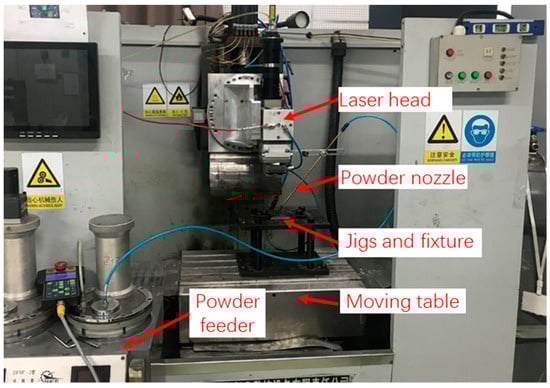
Figure 1.
The laser metal deposition system used in experiments.
Table 2.
Process parameters used in laser metal deposition experiments.
A forced cooling apparatus was designed to realize the fast cooling on the substrate, as shown in Figure 2. The apparatus had a dimension of 150 × 80 × 38 mm3, the bottom part was made of a carbon steel, and the top part was made of pure copper for a better cooling effects. During LMD, a substrate was clamped on the apparatus, while the cooling water flowing beneath the substrate and quickly taking the heat away. In contrast, the substrate specimen was fixed on a clamping jig that was made of a carbon steel in the conventional LMD process.
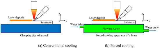
Figure 2.
Schematic diagrams of laser metal deposition (LMD) processes with different cooling conditions.
Single-pass deposits were produced with the aforementioned process parameters under two cooling conditions: one was the forced cooling (FC) with the developed water-cooling apparatus and the other is conventional cooling (CC) without cooling from the flowing water.
After laser deposition, the specimens were cut along the cross sections while using wire electrical discharge machining (WEDM) to prepare the samples for microstructure examination. The cross-section plane was perpendicular to the scanning direction (SD). The samples were then ground, polished, and finally etched with a solution of 4 g CuSO4 + 20 mL HCl + 20 mL H2O. The microstructures of deposits formed were observed with both optical microscopy (OM, Olympus Corporation, Tokyo, Japan) and scanning electron microscopy (SEM, FEI Company, Hillsboro, OR, USA). Meanwhile, the number of cracks was counted and the lengths of cracks were measured over five cross sections of the deposit for each cooling condition.
2.2. Numerical Analysis
The thermal and mechanical processes were numerically investigated for the LMD of the directionally solidified IC10 under two cooling conditions, i.e., the conventional cooling and the forced cooling to reveal the causes of cracking and the influences of cooling conditions in laser metal deposition. The numerical analysis was implemented by using the thermal elastic-plastic finite element method (FEM) solver JWRIAN-hybrid developed by authors.
In the thermal elastic-plastic analysis, an indirect coupling scheme was adopted for analyzing the temperature and stress in LMD, in which a thermal analysis was first carried out to obtain the temperature distribution and thermal history, and then a mechanical analysis was carried out to obtain the distribution and history of stresses. The temperatures that were obtained in the thermal analysis were applied as a thermal load in the following mechanical analysis. In thermal analysis, the eight-node thermal brick solid elements were used, while, in mechanical analysis, the corresponding eight-node brick mechanical solid elements were used.
Figure 3 shows the finite element meshes constructed for the two LMD processes. The dimensions of the substrates were 70 mm × 24 mm × 4 mm, and the profiles of deposits were incorporated in the finite element meshes according to their real dimensions that were experimentally obtained. Finer elements were used for the deposits and heat affected zone where high thermal gradients exist, while, for the substrate region far away from the deposit/substrate interface, the mesh sizes were increased.
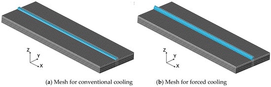
Figure 3.
Finite element meshes used in numerical analysis.
The laser heat source was assumed to a heat flux having a Gaussian distribution described, as follows:
in which, was the heat flux, P the laser power, and the radius of laser heat source, which was set to be 1.25 mm in the modelling, and r was the distance to the laser center.
The convective cooling boundary condition was applied to the underside of the substrate to model the heat transfer between the bottom surface of the substrate and the jigs. Different convective coefficients were chosen in order to model the different cooling effects by the conventional and the forced cooling conditions. For conventional cooling condition, a convective heat transfer coefficient of 1000 W/m2K was applied on the bottom surface of specimen, while, for force cooling conditions, a constant temperature of 20 °C was assumed for the bottom surface of the substrate. A natural convection coefficient of 100 W/m2K was applied on the other surfaces of the substrates, except for the bottom surface, as shown in Figure 4.
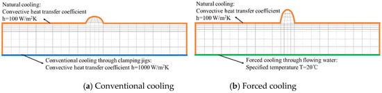
Figure 4.
Heat transfer boundary conditions used in finite element analysis (FEA).
Table 3 lists the thermo-mechanical property parameters and Figure 5 presents the temperature dependence of yield strengths used in the finite element analysis (FEA). Some of them were cited from the literature [9], and others were obtained using JMatPro 9.0 (Sente Software, Surrey, UK), which was software for computing the property parameters of materials. The process parameters used in the FEA were the same as those for experiments, as given in Table 2.
Table 3.
Property parameters of IC10 used in numerical analysis [17,18].
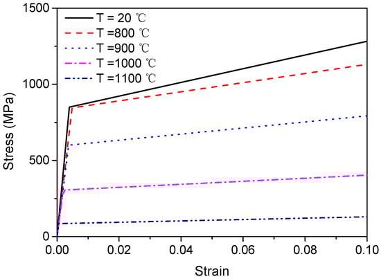
Figure 5.
Stress-strain curves of the IC10 superalloy under various temperatures used in finite element analysis (FEA).
3. Results
3.1. Experimental Results
Figure 6 shows the morphologies of the cross sections of the laser deposits produced with two cooling conditions. It can be found that the shapes of the deposits are notably different, and the height of deposit that formed under forced cooling conditions is much larger than that under conventional cooling conditions, which demonstrates the clear influence of the cooling condition on the laser deposition process. Cracks can be seen in both samples, which are located around the interface regions, as marked by squares in the figures. It can be found from the enlarged cracks that are shown in Figure 7 that these cracks extend across the interface bonding zones between substrates and deposits, and along the grain boundaries between the directional solidified columnar dendrites in both substrates and deposits (Figure 7a). In addition, liquation cracks are always associated with eutectics having low melting points (Figure 7b).
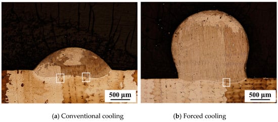
Figure 6.
Cross sections of deposits produced under two cooling conditions (OM).
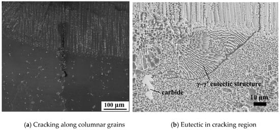
Figure 7.
Liquation cracks at the substrate/deposit interface produced in LMD of IC 10 superalloy (SEM).
The cracks were quantitatively characterized in terms of total cracking lengths, average cracking lengths, total number of cracks, and the average number of cracks per unit width of a deposit. The crack lengths were measured and the number of cracks were counted over five cross sections of the single-pass deposit for each LMD cooling condition, and Table 4 lists the results. It can be found that the total crack lengths, average crack length, total number of cracks, and the number of cracks per unit width in the five sections of the deposit formed under conventional cooling conditions are all larger than those under forced cooling conditions. The beneficial effects in mitigating the cracks are evident from the experimental findings by employing the additional forced cooling in LMD.
Table 4.
Lengths and numbers of liquation cracks under two cooling conditions.
3.2. Numerical Results
With the developed numerical model, the developments and distributions of temperature and stress were numerically obtained for the LMD processes with different cooling conditions. As the cracks are mainly found nearby the deposit/substrate interface and within the HAZ of substrates, the temperatures and stresses of three points in this region are mainly analyzed, as indicated in Figure 8.
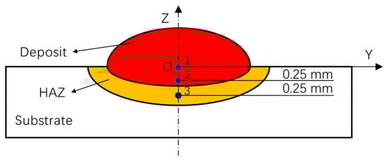
Figure 8.
Positions of the three points of which the thermal and stress histories were presented.
3.2.1. Results of Thermal Analysis
Figure 9 shows the variations of temperatures with time for the three points in the cross section at the middle of the specimen (X = 35mm), where the LMD process has already reached a quasi-steady state. It can be seen from Figure 9 that, for both cooling conditions, the temperatures of these points quickly increase when the laser approaches, reach maximum values, and then decreases after the laser passes. The decreasing of temperature is quick at first, and it then gradually slows down. Under a given cooling condition, the maximum temperature at the interface (Z = 0 mm) is the highest among the three selected points, and the highest temperatures decrease with the increasing of distances to the deposit/substrate interface. When compared to the conventional cooling conditions, the maximum temperature is lower under the forced cooling condition at each of the three positions. In addition, the temperatures decrease to room temperature (25 °C) within 20 s for forced cooling condition, while the temperatures are still high at about 200 °C after 20 s of conventional cooling. Apparently, this results from the higher cooling rate when the forced cooling is applied.
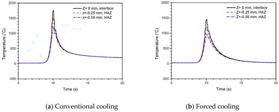
Figure 9.
Thermal histories of three points in the substrate during LMD with two cooling conditions.
Figure 10 shows the distributions of temperature in the cross sections of substrates after reaching the quasi-steady state under the two cooling conditions. It can be seen that the distribution patterns of temperature are similar for the two cooling conditions, the temperatures are the highest in the deposits, lower at the deposit/substrate interfaces, and then further decrease in the substrate with the increase of distance to the interface. The cooling condition mainly affects the depth of the high-temperature region in the substrate, which is notably reduced by using the forced cooling in comparison with that obtained under conventional cooling conditions.
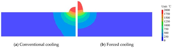
Figure 10.
Distributions of temperature in the cross sections under two cooling conditions.
3.2.2. Results of Mechanical Analysis
Figure 11 presents the variations of the normal stress in transverse direction (σy) with time for the three points being shown in Figure 8 during LMD with two cooling conditions. It can be seen that, when the laser is approaching, stresses in tension are first developed and they increase to a maximum; afterwards, the tensile stresses decrease and the compressive stresses begin to develop and increase with time. The compressive stresses are at the highest level when the laser reaches the position of the point. When the laser source moves away, the compressive stresses quickly decrease to zero within a short time, and tensile stresses begin to form again. The tensile stresses increase very rapidly at first, and then at reduced rates. The tensile stress nearby the interface (Z ≥ −0.25 mm) might slightly decrease with time; such a decrease is absent for the point relatively far away from the interface (Z = −0.5 mm). For all three points, the tensile stresses finally reach a stable state and no longer change with time.
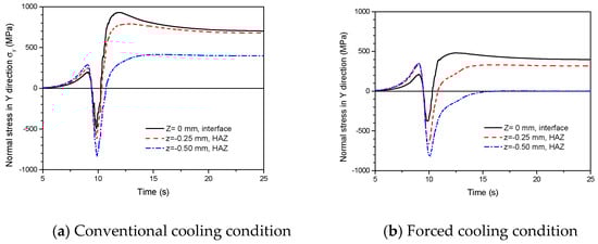
Figure 11.
Variation of stress with time for the three points in the substrates during LMD under two cooling conditions.
For both cooling conditions, the tensile stresses that developed when laser approaching are lower than those tensile stresses developed when laser leaving afterwards, and the tensile stresses at the deposit/substrate interface are much larger than those away from the interface. The application of the forced cooling condition significantly decreases the tensile stresses near the deposit/substrate interface region. For instance, the maximum tensile stress is 930.7 MPa at the interface for the conventional cooling condition, while it is only 480.7 MPa for the forced cooling case; moreover, for the point 0.5 mm below the interface (Z = −0.50mm), the residual tensile stress is basically zero when the forced cooling is applied, while there still exists high residual tensile stress of about 400 MPa under conventional cooling conditions.
When considering the high tensile stresses in the specimens are mainly generated during the cooling period, as shown in Figure 11, the distributions of the transversal stresses (σy) in the cross sections of substrates at different cooling stages are presented in Figure 12 for the LMD with two different cooling conditions.
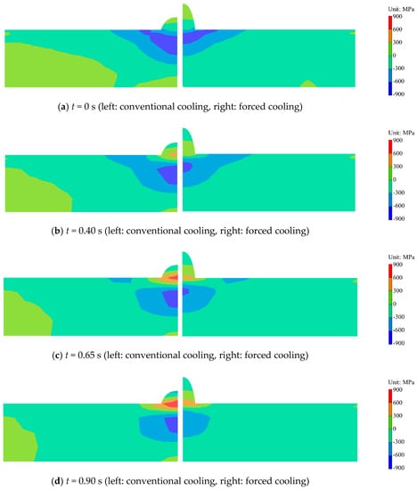
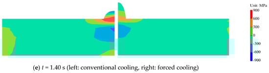
Figure 12.
Distributions of the transversal stress (σy) in the cross sections of substrates at different stages of LMD using two different cooling conditions (t = 0 is the time when the laser has just arrived at the position).
When the laser heat source arrives at the position (t = 0 s), the central part of the specimen is heated and then expands. Because such an expansion is restrained by surrounding metals, compressive stresses are developed around the deposit/substrate interface. The region with high compressive stress (greater than 300 MPa) is smaller for the forced cooling condition than that for conventional cooling.
After a cooling process of 0.65 s, the compressive stresses around the interface region have changed to tensile stresses because of the decrease in temperature and accompanying metal shrinking. The maximum tensile stresses exist in the narrow regions near the deposit/substrate interface. When the forced cooling condition is used, the maximum tensile stress is smaller and the high-stress region in the substrate is shallower than those that were obtained under the conventional cooling condition.
With the increasing of cooling time (t = 0.65–1.4 s), the regions with high tensile stress enlarge in both thickness and width directions within the cross sections, as a result of the gradual increase of tensile stress with time. Obviously, the highest tensile stress and the dimensions of the region with high-stress region are both smaller when the forced cooling conditions is used for all of these time points.
4. Discussion
The IC10 superalloy that was used in this study was a solid solution strengthened directionally solidified nickel based superalloy. Its microstructure is mainly composed of nickel-based solid solution phase γ, intermetallic compound phase γ’ (Ni3Al), low melting point eutectic γ-γ’, and carbides (TaC and HfC) [15]. The eutectic γ-γ’ products mainly exist along the boundaries between the directional columnar dendrites of γ. When heated during laser deposition, the eutectics in HAZ may melt due to its lower melting point than the γ dendrites, resulting in liquefied and very weak grain boundaries. It is revealed by the present numerical analysis that high tensile stresses are developed around the deposit/substrate interface during the cooling of LMD process, where the temperatures are still high, as shown in Figure 13. Consequently, the weak eutectic will be broken and cracks will form along the columnar grains boundaries. The cracks may further propagate from HAZ into the deposit layer under high tensile stress around the deposit/substrate interface during the subsequent cooling process, resulting in the cracks that are shown in Figure 6 and Figure 7. Such cracking behavior has also been found in LMD of other types of directionally solidified superalloys [5,8].
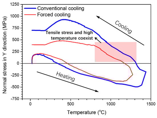
Figure 13.
Curves of temperature versus normal stress σy for a point in HAZ (Z = −0.25 mm) under two cooling conditions.
The introduction of the forced cooling in the present study on the bottom surface of a substrate by flowing water will decrease the temperature and reduce the high-temperature zone in the HAZ of the substrate, which means that a reduced volume of melted eutectics formed between columnar grain boundaries during LMD. Meanwhile, the forced cooling also reduces the tensile stress and the thickness of the region with high tensile stress. Such alleviation effects in both thermal and mechanical aspects, which are also shown in Figure 13, contribute to the mitigation of cracks in HAZ by the forced cooling in the LMD of the directionally solidified superalloys, as experimentally revealed.
Beside the cracking behavior, the application of forced cooling may also influence the resultant microstructures and therefore the mechanical properties of the laser deposits. Amorphous phases may even be formed under extreme conditions [19]. The characterization of the local microstructures and the mechanical properties of laser deposits will be carried out in the future to evaluate the integrity of the structures repaired by LMD [20].
5. Conclusions
The liquation cracks could be effectively mitigated by applying forced cooling on the bottom of substrates during LMD of the directionally solidified superalloy IC10.
The forced cooling reduces the highest temperature and tensile stress in the substrate, and it also minimizes the regions with high temperature and tensile stress, which contributes to the reduction of liquation cracks in LMD of the directionally solidified superalloy.
Author Contributions
B.C. and W.L. conceived and developed the numerical model; S.Y. and G.L. performed the experiments; D.D. and N.M. analyzed the data; B.C. wrote the paper. All authors have read and agreed to the published version of the manuscript.
Funding
This research was funded by the National Natural Science Foundation of China, grant number 51675303, and the State Key Laboratory of Tribology, grant number SKLT2018B05. The APC was funded by the National Natural Science Foundation of China.
Acknowledgments
The authors gratefully appreciate the financial supports from the National Natural Science Foundation of China (No. 51675303) and the State Key Laboratory of Tribology (SKLT2018B05).
Conflicts of Interest
The authors declare no conflict of interest.
References
- McNutt, P.A. An Investigation of Cracking in Laser Metal Deposited Nickel Superalloy CM247LC. EngD Thesis, University of Birmingham, Birmingham, UK, 2015. [Google Scholar]
- Xing, B.; Chang, B.H.; Yang, S.; Du, D. A study on the cracking behavior in laser metal deposition of IC10 directionally solidified nickel base superalloy. Mater. Res. Innov. 2015, 19, 281–285. [Google Scholar] [CrossRef]
- Chauvet, E.; Kontis, P.; Jägle, E.A.; Gault, B.; Raabe, D.; Tassin, C.; Blandin, J.J.; Dendievel, R.; Vayre, B.; Abed, S. Hot cracking mechanism affecting a non-weldable Ni-based superalloy produced by selective electron beam melting. Acta Mater. 2018, 142, 82–94. [Google Scholar] [CrossRef]
- Wang, N.; Mokadem, S.; Rappaz, M.; Kurz, W. Solidification cracking of superalloy single- and bi-crystals. Acta Mater. 2004, 52, 3173–3182. [Google Scholar] [CrossRef]
- Zhong, M.L.; Sun, H.Q.; Liu, W.J.; Zhu, X.F.; He, J.J. Boundary liquation and interface cracking characterization in laser deposition of Inconel 738 on directionally solidified Ni-based superalloy. Scr. Mater. 2005, 53, 159–164. [Google Scholar] [CrossRef]
- Sun, H.Q.; Zhong, M.L.; Liu, W.J.; He, J.J.; Li, X.L.; Zhu, X.F. Cracking Sensitivity on Laser Cladding Inconel 738 on Directionally Solidified Ni-base Superalloy. J. Aeronaut. Mater. 2005, 25, 26–31. (In Chinese) [Google Scholar]
- Li, L. Repair of directionally solidified superalloy GTD-111 by laser-engineered net shaping. J. Mater. Sci. 2006, 41, 7886–7893. [Google Scholar] [CrossRef]
- Xi, M.Z.; Gao, S.Y. Microstructures and mechanism of cracks forming of Rene 80 high-temperature slloy fabricated by laser rapid forming process. Chin. J. Lasers 2012, 39, 1–6. (In Chinese) [Google Scholar]
- Wang, D.S.; Tian, Z.J.; Wang, J.W.; Duan, Z.Y.; Shen, L.D.; Huang, Y.H. A method of crack control in laser cladding process with changing power density distribution of laser beam. Chin. J. Lasers 2011, 38, 82–86. (In Chinese) [Google Scholar]
- Wu, D.J.; Chu, Y.; Niu, F.Y.; Ma, G.Y.; Zhuang, J. Influence of temperature distribution of ceramic coating using top-hat assistant laser beam in dual-beam laser cladding. Chin. J. Lasers 2014, 41, 125–130. (In Chinese) [Google Scholar]
- Kaierle, S.; Overmeyer, L.; Alfred, I.; Rottwinkel, B.; Hermsdorf, J.; Wesling, V.; Weidlich, N. Single-crystal turbine blade tip repair by laser cladding and remelting. CIRP J. Manuf. Sci. Technol. 2017, 19, 196–199. [Google Scholar] [CrossRef]
- Liang, S.D.; Zhang, A.F.; Wang, T.; Li, D.C. Elimination of laser direct forming crack on DD4 parts by induction heating. Chin. J. Lasers 2017, 44, 234–243. (In Chinese) [Google Scholar]
- Chen, Y.; Lu, F.G.; Zhang, K.; Nie, P.L.; Hosseini, S.R.E.; Feng, K.; Li, Z.G. Dendritic microstructure and hot cracking of laser additive manufactured Inconel 718 under improved base cooling. J. Alloy. Compd. 2016, 670, 312–321. [Google Scholar] [CrossRef]
- Zhao, X.H.; Huang, Z.H.; Tan, Y.N.; Zhang, Q.; Yu, Q.; Xu, H.B. New Ni3Al-based directionally-solidified superalloy IC10. J. Aeronaut. Mater. 2006, 26, 20–24. (In Chinese) [Google Scholar]
- Zhao, X.H.; Huang, Z.H.; Tan, Y.N.; Zhang, Q.; Jia, X.Y.; Xu, H.B. Microstructure of IC10 superalloy. J. Aeronaut. Mater. 2008, 28, 28–33. (In Chinese) [Google Scholar]
- Xing, B.; Chang, B.H.; Du, D. Effects of process parameters on morphology of laser deposited layer on IC10 directionally solidified superalloy. Trans. China Weld. Inst. 2015, 36, 88–92. (In Chinese) [Google Scholar]
- Editorial Committee for the Handbook of Materials Data Used for Aeroengine Design; Aviation Industrial Publishing House: Beijing, China, 2014.
- Yang, S.; Chang, B.H.; Du, D. Studies of the influence of beam profile and cooling conditions on the laser deposition of a directionally solidified superalloy. Materials 2018, 11, 240. [Google Scholar] [CrossRef] [PubMed]
- Ghidelli, M.; Idrissi, H.; Gravier, S.; Blandin, J.J.; Raskin, J.P.; Schryvers, D.; Pardoen, T. Homogeneous flow and size dependent mechanical behavior in highly ductile Zr65Ni35 metallic glass films. Acta Mater. 2017, 131, 246–259. [Google Scholar] [CrossRef]
- Ast, J.; Ghidelli, M.; Durst, K.; Göken, M.; Sebastiani, M.; Korsunsky, A.M. A review of experimental approaches to fracture toughness evaluation at the micro-scale. Mater. Des. 2019, 173, 107762. [Google Scholar] [CrossRef]


© 2020 by the authors. Licensee MDPI, Basel, Switzerland. This article is an open access article distributed under the terms and conditions of the Creative Commons Attribution (CC BY) license (http://creativecommons.org/licenses/by/4.0/).