Article

Laboratory X-ray Diffraction Complex for In Situ Investigations of Structural Phase Evolution of Materials under Gaseous Atmosphere

School of Nuclear Science & Engineering, National Research Tomsk Polytechnic University, 30 Lenin Avenue, 634050 Tomsk, Russia
*
Authors to whom correspondence should be addressed.
Metals 2020, 10(4), 447; https://doi.org/10.3390/met10040447
Submission received: 6 March 2020 / Revised: 24 March 2020 / Accepted: 26 March 2020 / Published: 28 March 2020
(This article belongs to the Special Issue Phase Transformations and Physical Properties of Alloys)

Abstract

:
In this work, a laboratory X-ray diffraction complex for in situ investigations of structural phase evolution of materials under gaseous atmosphere and elevated temperatures was developed. The approbation of the complex was carried out using a commercially pure titanium (CP-Ti) powder, zirconium (Zr-1Nb) alloy and electron beam melted Ti-6Al-4V alloy. It was established that hydrogenation of the CP-Ti powder occurred at a temperature of 500 °C and a hydrogen pressure of 0.5 atm, accompanied by the formation of metastable γ titanium hydride (γ-TiH) phase. The lifetime of the γ-TiH phase was 35–40 min. Decomposition of the γ-TiH occurred after reaching a temperature of 650 °C as a result of the thermally stimulated desorption of hydrogen. The α-Zr → δ-ZrH phase transformation was observed under hydrogenation of the zirconium Zr-1Nb alloy at a temperature of 350 °C and a hydrogen pressure of 0.5 atm. It was revealed that the increase in hydrogenation temperature to 450 °C accelerated this transformation by two times. Hydrogenation of the electron beam melted titanium Ti-6Al-4V alloy at a temperature of 650 °C and hydrogen pressure of 0.5 atm was accompanied by the α → α + β → β + α2 phase transformations.

1. Introduction

One of the most important tasks of modern materials science is the development of new functional materials and technological processes. An important requirement of materials is the ability to operate extreme conditions, including low or high temperatures, aggressive media (chemical, radiation, etc.), high mechanical loads, high pressure, etc. [1,2,3,4,5]. Modern physical and chemical methods are usually used to assess the operational properties of materials used in aggressive environments. The basic and most popular method of materials diagnostics is X-ray diffraction [6,7,8,9]. This method has been widely used due to the simplicity and fast processing of data on material structure and phase composition.
Today, data on structural and phase evolution of materials during interaction with aggressive media at elevated temperatures and pressures are of both fundamental and practical interest. On the basis of such data, it becomes possible to predict and evaluate their physical and mechanical properties [10,11]. Experimentally, such information can be obtained from in situ XRD measurements [12,13,14]. The vast majority of such studies are conducted using synchrotron radiation sources, due to high beam intensity, low divergence and a continuous spectrum in a wide range of photon energies [15,16,17,18]. However, access to all synchrotron radiation sources is limited, which restricts their wide application. Currently, the development of hardware for X-ray diffractometers—namely, beam collimation systems, high-speed detectors, as well as a large number of attachments and sample holders with a special design for conducting research in special conditions (high temperature, vacuum or air, etc.)—enables in situ XRD measurements [19,20,21]. X-ray detectors play an important role in diffraction measurements [22]. The first electronic detectors appeared in the early 1990s: multiwire proportional counters (Siemens/Bruker X-1000), television-camera detectors (FAST developed by Uli Arndt) and electronically controlled imaging plates (MAR Research and Rigaku) [23]. However, the data collection rate of such X-ray detectors was not high, which prevented their application for in situ measurements. Recently, two technologies have been actively developed in the design of X-ray detectors: the application of an active-pixel complementary metal-oxide semiconductor (AP CMOS) chip (Bruker Photon100) and hybrid-pixel photon-counting devices (PILATUS detectors by Dectris). X-ray detectors based on silicon strip detector technology have become standard X-ray diffraction instruments and are available from several companies: LYNXEYE detectors from Bruker, HyPix detector from Rigaku, OneSight Wide-Range High-Speed by Shimadzu and other [24,25,26,27].
Despite this, serial laboratory diffractometers—which make it possible to study the structural and phase states of materials under aggressive conditions in a wide temperature ranges in situ—are not sufficiently developed. Thus, further improvement of the experimental base of serial laboratory diffractometers is necessary to study phase composition and structural changes in polycrystalline materials in-situ—with a time resolution under aggressive atmospheres and elevated temperatures. The available commercial systems have some limitations. For example, there are no high temperature gas injection systems working with hydrogen.
The goal of this work is to develop and test laboratory X-ray diffraction complex for in situ investigations of the structural phase evolution of materials under gaseous atmosphere at elevated temperatures. It is necessary that the XRD complex allows performing in situ XRD measurements at wide temperature ranges with high resolution.

2. Materials and Methods

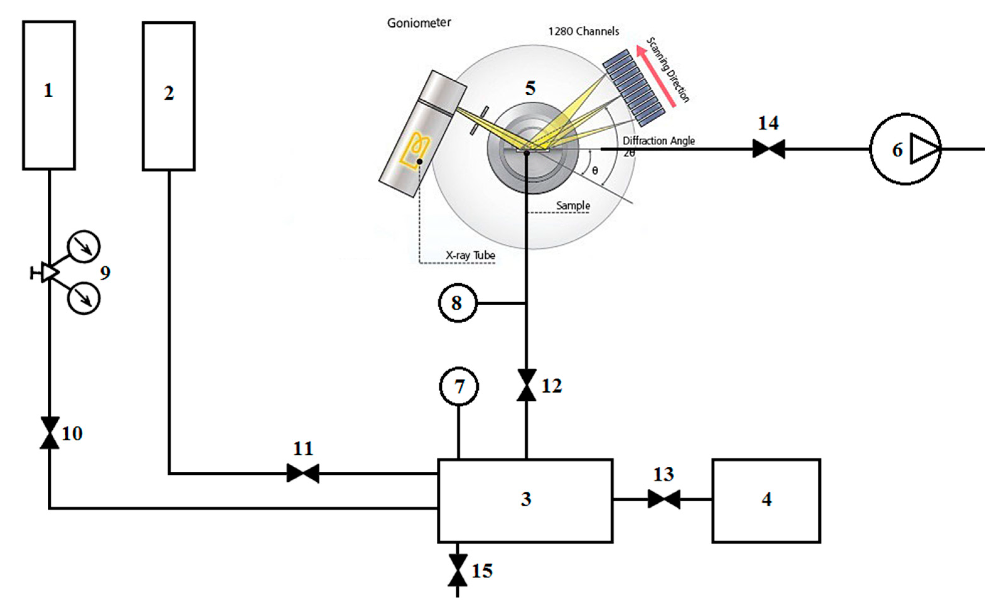
2.1. Diffraction Complex

A diffraction complex for structural and phase investigations of polycrystalline materials at elevated temperature and in gaseous atmosphere was designed on the basis of the laboratory diffractometer Shimadzu XRD 7000S (Shimadzu, Kyoto, Japan) equipped with vertical goniometer. The scheme of the diffraction complex is demonstrated in Figure 1. The diffraction complex consists of 3 main parts: X-ray tube with copper (Cu) anode; high speed matrix detector and gas supply system connected to a high temperature chamber.
A standard X-ray tube with a copper anode was used as a radiation source. The use of the copper anode was due to the relatively low manufacturing cost and short radiation wavelength (λ = 1.54 Å).
Study of structural and phase transformations in the materials under high temperature were provided using an HTK 2000N high temperature chamber (Anton Paar, Graz, Austria). The heating filament was a metal plate made of tungsten or platinum, which was heated by resistive method. The temperature was measured by a tungsten-rhenium thermocouple (W3Re/W25Re) for the W heating filament or platinum-rhodium (Pt/Pt10Rh) in the case of a Pt heating filament fixed to the back side of the plate. The tungsten heating filament provides an opportunity to conduct research experiments in the temperature range of 25–2300 °C in vacuum or hydrogen atmosphere. The use of a platinum heater provides experiments in the temperature range of 25–1600 °C both in vacuum and in gaseous atmosphere including air. There was a temperature gradient between the heater and the surface of the sample under experiments. Since thin layer of materials was used in all experiments to reduce the temperature gradient. Temperature stability was only affected by the moment when the gas was injected into the chamber. The stabilization of temperature took 1–2 min. The maximum heating/cooling rate was 500 °C/min.
The application of high-speed widespread OneSight detector (Shimadzu, Kyoto, Japan) provides the opportunity for in situ investigations of structural phase evolution in the materials. The detector was a linear silicon multi-band 1280-channel matrix, which performance significantly exceeds the scintillation counter. The detector was capable of recording diffraction patterns in two modes: with the movement of the goniometer and in a fixed range of angles. In the second mode, the diffracted intensity was detected with an angular scan ~8°. The exposure time in this case varies from a few seconds to tens of minutes, depending on the experimental procedure. The technical specifications of the OneSight detector are presented in Table 1.
An inert and aggressive environment was created through a regulated gas supply system developed at the Experimental Physics Department at Tomsk Polytechnic University. The system was equipped with an inert gas cylinder, a hydrogen generator, a gas storage chamber, a gas mixer, a gas pressure regulator, two pressure sensors, control valves and a vacuum pumping system based on fore-vacuum and turbomolecular pumps. Gas sources were helium, argon and hydrogen cylinders, as well as a hydrogen generator. The system implements were capable of supplying two different gases, as well as their mixtures. To obtain a mixture of gases in the required proportion, a temporary gas storage chamber was used. This chamber was an insulated vessel with a volume of 155.5 cm3 with a wall thickness of 0.4 cm and a maximum working pressure of 2 atmospheres. The chamber was made of Inconel 600 superalloy. The calculation of the gases proportion necessary for the experiment was carried out based on the known volume of the temporary storage chamber.
The main connecting element of all nodes of the system was a gas mixer, representing a hollow cylinder with a flange connection for a pressure sensor and five outlets for connection to a gas main. A gas mixer made of stainless steel and had 2 outlets for connecting gas sources, 2 outlets for connecting the temporary storage chamber and a high-temperature chamber and 1 outlet for discharging gas (or a mixture of gases) into the air.
Pressure was controlled using DualTrans MicroPirani/Absolute Piezo 910 pressure sensors (MKS Instruments, Andover, MA, USA) connected to a high-temperature chamber and a gas mixer. Technical specifications of indicated sensors are presented in Table 2.

2.2. Characterization

The diffraction complex was tested on the set of construction materials under hydrogenation at elevated temperatures. The zirconium Zr-1Nb alloy, commercially pure titanium powder and titanium Ti-6Al-4V alloy produced by electron beam melting were chosen as test materials. The EMB samples were produced from powder of titanium Ti-6Al-4V alloy (Ti6Al4V ELI) using ARCAM A2 EBM (Arcam AB, Mölndal, Sweden) machine [28]. The powder was purchased from ARCAM AB. The powder particle size was varied from 50 μm to 150 μm. The samples were coin shaped with the diameter 8 mm and height 2 mm. All the samples were manufactured in the same batch with the built direction parallel to the round surface. Powder layer thickness was 70 μm and standard ARCAM parameter settings for solid Ti64 were used. The samples were carefully blasted in the ARCAM powder recovery system using the same precursor powder. Finally, all samples were mechanically grinded to obtain homogeneous surface.
Scanning electron microscopy and analysis of the hydrogen absorption curves and were used to confirm XRD measurements. The hydrogenation kinetics was investigated by the Sieverts volumetric method using the automated Gas Reaction Controller (AMC, Pittsburgh, PA, USA) [29]. The hydrogen purity was 99.9995%. The sample was placed in the chamber, evacuated to 10−6 mbar during 1 h and heated with a linear rate of 6 °C /min at different temperatures. The microstructural analysis was carried out by Quanta 2003D (FEI Company, Hillsboro, OR, USA) scanning electron microscope (SEM).

3. Results and Discussion

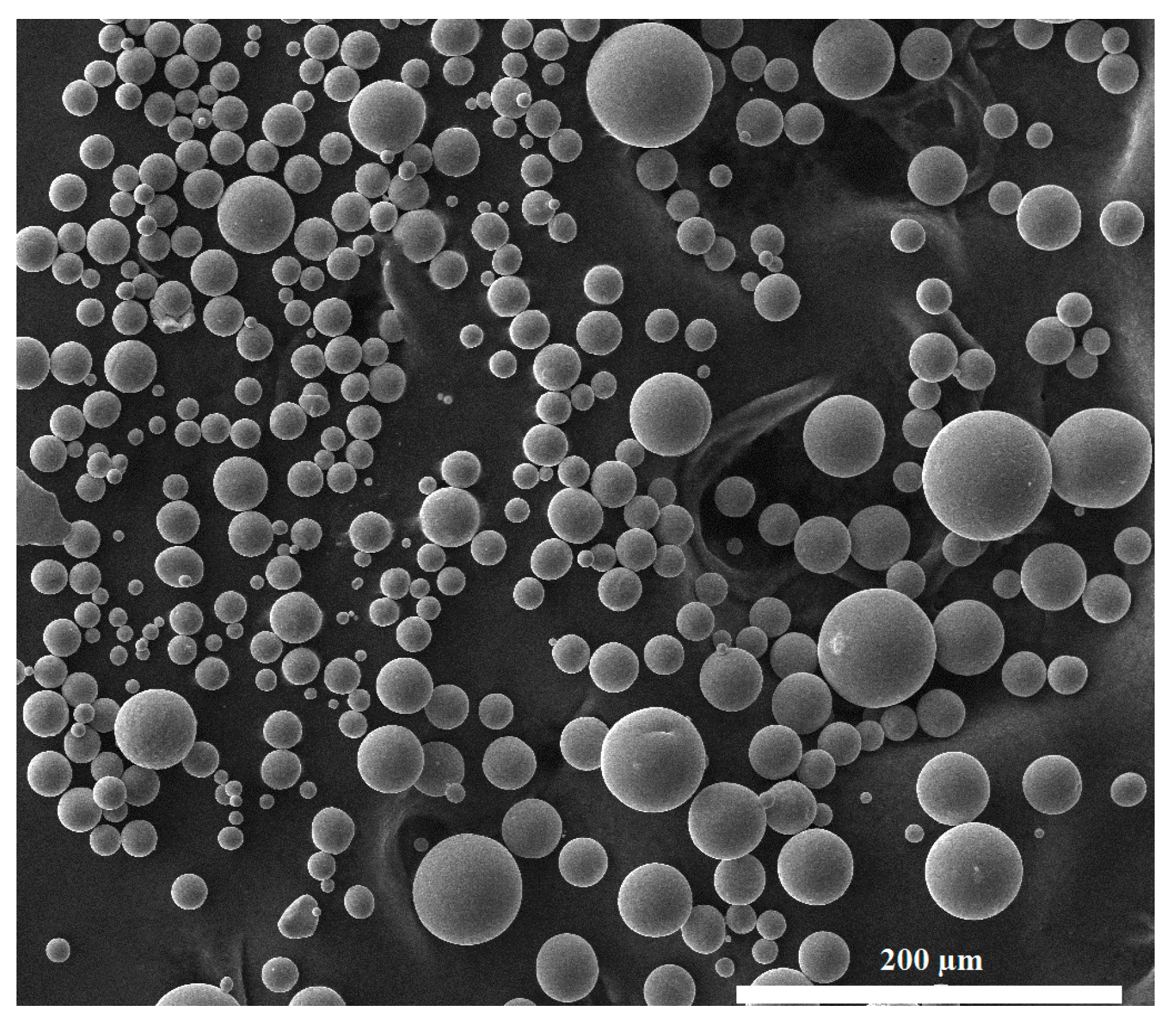
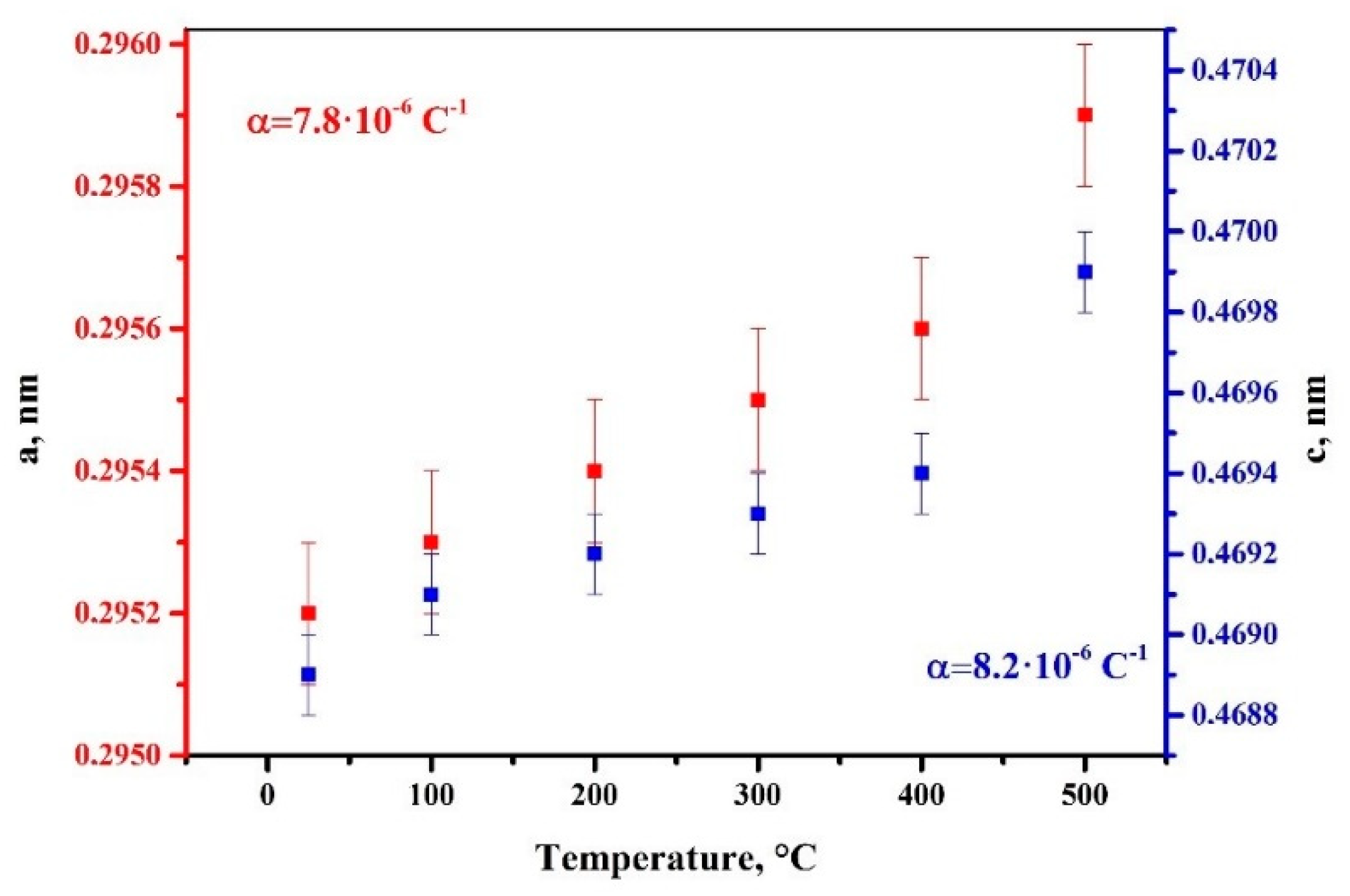
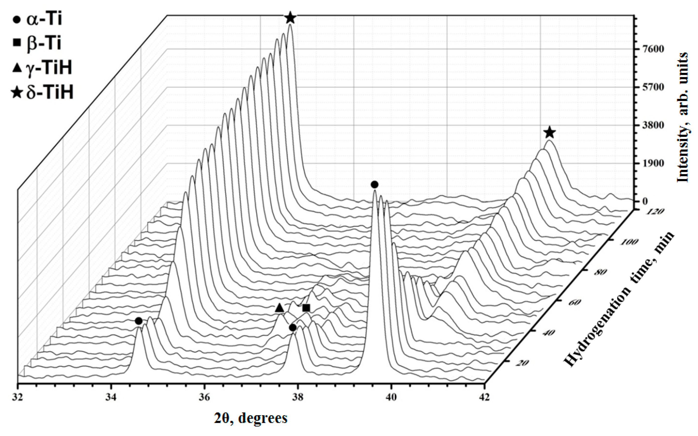
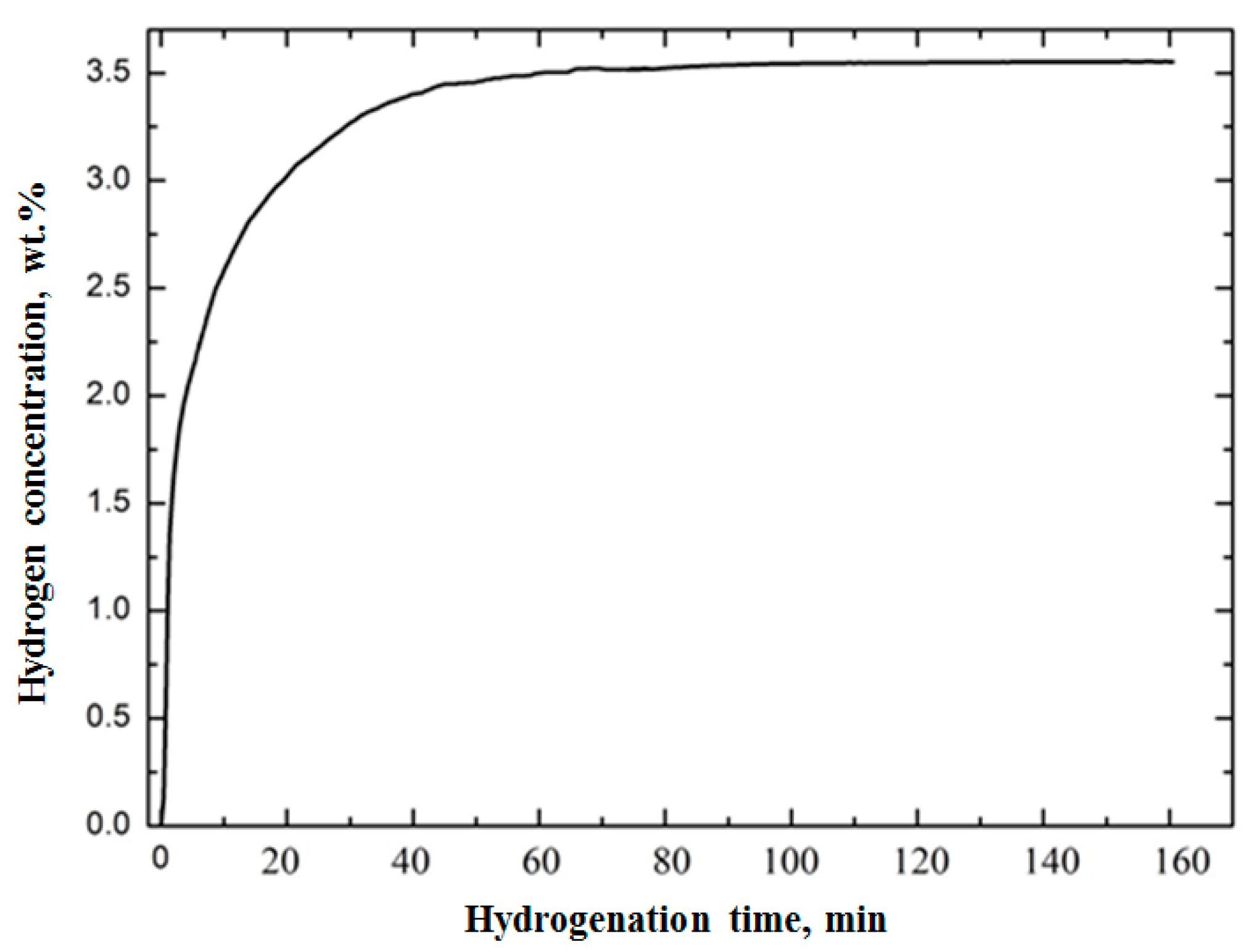
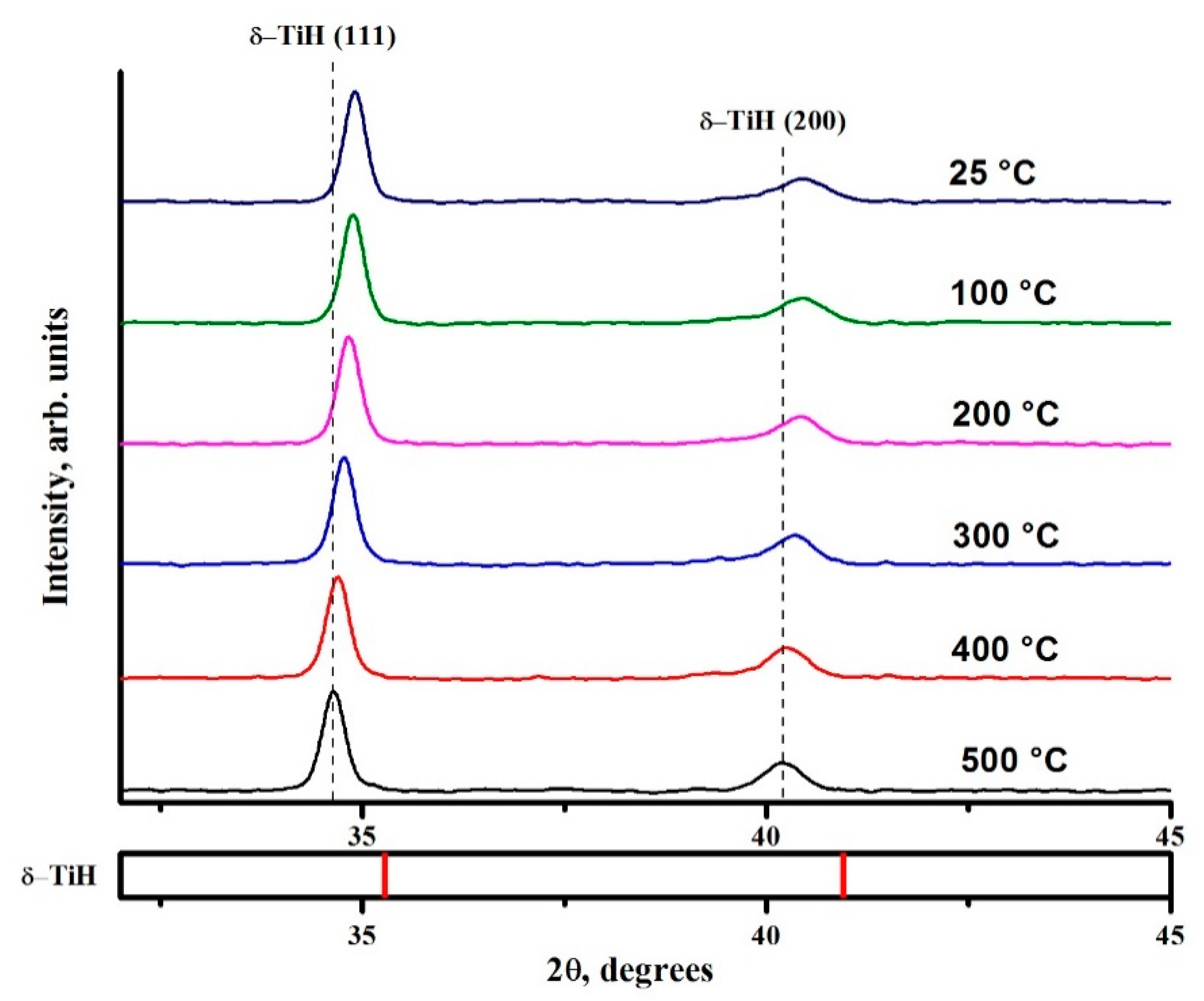
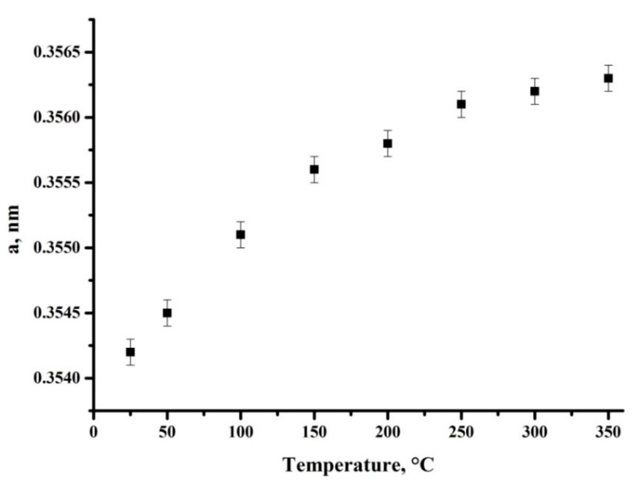
3.1. Verification of the System Using Commercially Pure Titanium Powder

A commercially pure titanium powder obtained by plasma atomization method in an inert gas atmosphere was selected to test the capabilities of the developed diffraction instrumentation. The purity of commercial pure titanium is 99.7%. The powder particles of 20–80 μm dispersion had a spherical shape (Figure 2). The average size of particles was 19 μm, the largest particles were 75 μm in size. The majority of the investigated powder had dispersion of 6–30 μm.
Phase transformations and structural parameters changing in the material were investigated in the processes of linear heating, gas phase hydrogenation and cooling. Diffraction patterns were recorded in the 2θ range of 30–55° and the exposure time of 5 min per shoot. Evaluation of the diffraction complex capabilities was carried out in 4 stages.
In the first stage, the samples were fixed in the high-temperature chamber, pumped to residual pressure of 2 × 10⁻⁴ mbar and heated from room temperature (RT) to 500 °C at the heating rate of 5°/min. Figure 3 shows diffraction patterns of the CP-Ti in the process of linear heating in vacuum to 500 °C.
XRD analysis shows that the raw powder of the commercially pure titanium has only α-Ti phase with hexagonal close-packed (hcp) lattice (а = 0.2951 nm and с = 0.4689 nm). The increase in temperature leads to a shift of the all α-Ti phase reflections towards small angles, which indicates the increase in lattice parameters due to thermal expansion of the sample. The change of the lattice parameters of the commercially pure titanium powder was determined by the shift of the reflections using Rietveld refinement. Graphs of changes in parameter a (red curve) and c (blue curve) with increasing heating temperature are presented in Figure 4. The coefficients of thermal expansion (CTE) of the commercially pure titanium powder in the temperature range of 25–500 °С were calculated from the linear areas of the curves. The spread of the CTE values for titanium in the indicated range is from 7.7·× 10−6 С−1 to 10.4·× 10−6 С−1 [30]. The values obtained from the experiment fall into this interval, which indicates the correct operation of the complex.
In the second stage, the samples were hydrogenated from gas atmosphere at a temperature of 500 °C and hydrogen pressure of 0.5 atm. The exposure time from each diffraction pattern was 5 min/shoot, the 2θ angles range was 32–42°. In situ phase transformations in the titanium-hydrogen system under gas phase hydrogenation are presented in Figure 5.
In the first stage of hydrogenation (about 15 min), there were no significant changes in the diffraction patterns, which was associated with the hydrogen dissolution in the α-Ti phase. Moreover, hydrogenation process may be complicated by an oxide film on the surface of powder particles [31]. Hydrogenation up to 20 min led to redistribution of the α-Ti phase intensities, as a result the intensity of (100) reflection increases. This fact indicated the formation of the δ titanium hydride phase with a face-centered cubic (fcc) lattice whose (111) reflection overlaps with the (100) reflection of the α phase. Along with the formation of δ hydride, the β phase of titanium with a body-centered cubic (bcc) lattice appeared in the diffraction patterns. It is known that hydrogenation of commercially pure titanium can reduce the temperature of α → β polymorphic transformation [32]. Further hydrogenation (25 min) led to an increase in the content of δ and β phases, as well as to the appearance of a metastable phase of γ titanium hydride. The lifetime of the metastable phase was 35–40 min. After 65 min of hydrogenation, reflections of the β phase and γ hydride were not observed in the diffraction patterns, which was associated with the γ titanium hydride decomposition and the complete transformation of titanium to stable δ hydride. Thus, it was revealed that the gas phase hydrogenation of the commercially pure titanium at 500 °C and 0.5 atm pressure was accompanied by α → α + δ → α + β + γ + δ → δ phase transformations.
The dependence between the concentration of absorbed hydrogen and hydrogenation time of the commercially pure titanium at 500 °C and 0.5 atm pressure is presented in Figure 6. The analysis of the kinetic curve showed that the formation of a stable δ titanium hydride occurred after 60 min of hydrogenation. These data are well correlated with XRD data presented in references [33,34] and the current work.
In the third stage, the samples were cooled in the hydrogen atmosphere with the cooling rate was 5°/min. The diffraction patterns were recorded every 5 min and presented in Figure 7. The cooling from 500 °C to room temperature (RT) under hydrogen atmosphere did not change the phase composition of the material. According to XRD, only shifting of the δ hydride phase reflections towards small angles caused by temperature was observed.
The final stage of testing the developed diffraction complex was the study of thermally stimulated decomposition of the formed δ titanium hydrides. The chamber with the samples was evacuated to residual pressure of 2·× 10−4 mbar and heated from RT to 800 °C. The heating rate was 5°/min, exposure time was 5 min/shoot. Figure 8 shows the diffraction patterns in the process of thermally stimulated hydrogen release from commercially pure titanium.
The results of XRD analysis show that the decomposition of δ hydride phase began at a temperature of 225–250 °C. The (200) reflection of the δ hydride phase acquired asymmetry due to the superposition with the most intense (101) reflection of the α phase, which formed during the thermally stimulated release of hydrogen from the sample. An increase in temperature to 450–475 °C led to the formation of a metastable γ hydride, along with a decrease in the volume content of δ hydride and an increase in the content of α phase. The complete decomposition of γ and δ hydrides occurred at a temperature of 650 °C. A further increase in temperature did not lead to phase changes in the system of commercially pure titanium-hydrogen. Thus, the thermally stimulated release of hydrogen from commercially pure titanium powder was accompanied by δ → δ + α → α + δ + γ → α phase transformations. Similar phase transformations during thermally stimulated release of hydrogen from hydride powder of commercially pure were observed in [35].

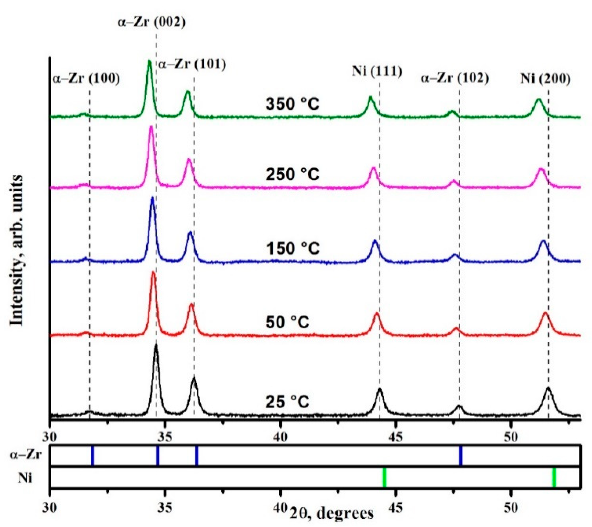
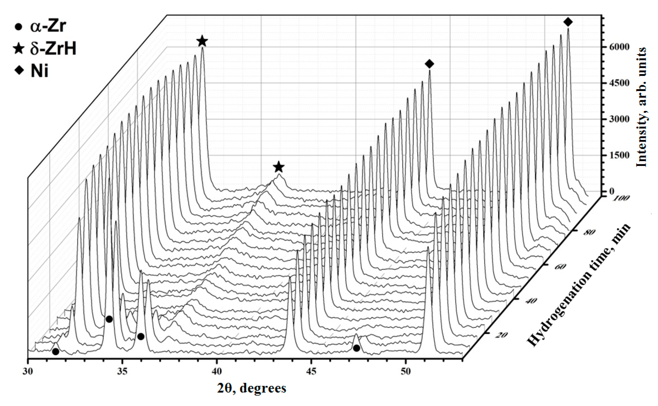
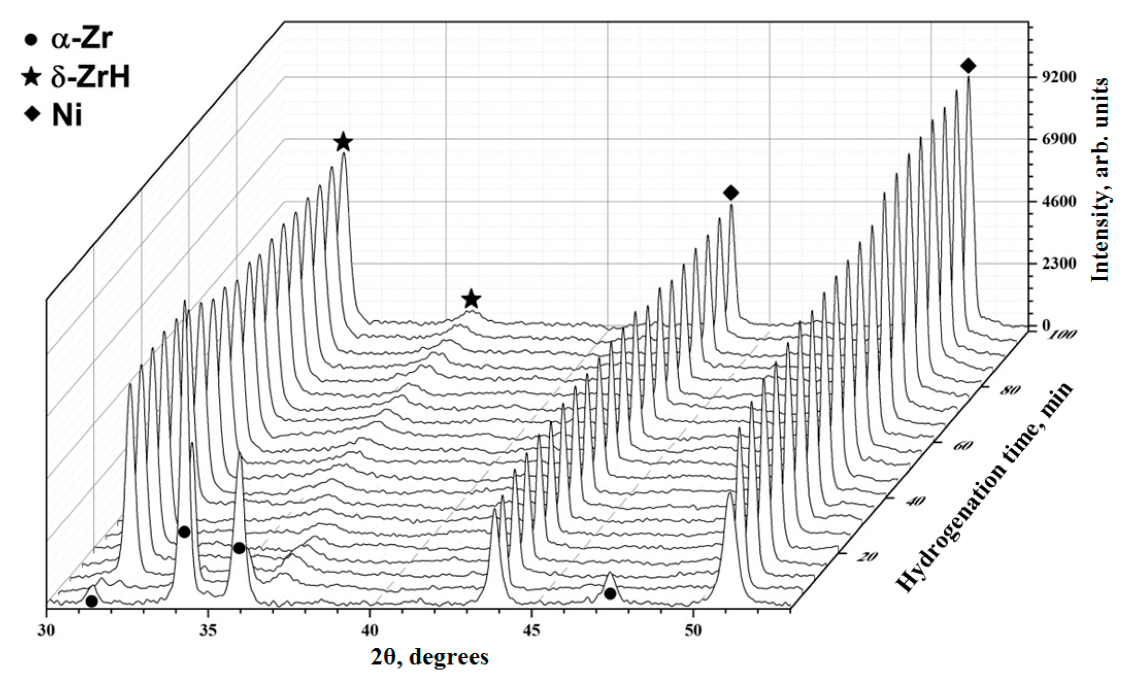
3.2. Structural and Phase State of Zr-1Nb Alloy with Nickel Coating under Hydrogenation

Figure 9 shows diffraction patterns of the zirconium Zr-1Nb alloy with nickel coating in the process of linear heating to the temperature of 350 °C in vacuum. The nickel coating (~1 µm) was deposited by magnetron sputtering to eliminate the effect of possible surface oxidation of the zirconium alloy during the experiments. According to XRD analysis, the initial alloy consisted of α zirconium phase with hcp lattice and nickel phase with fcc lattice. It should be noted that for the α zirconium phase, the crystallites predominantly oriented in the (002) direction, which was associated with the texture along the rolling direction. Heating of the samples causes shifting of all the reflections of α-Zr and Ni phases towards smaller angles, which indicates the lattice expansion.
The evolution of the lattice parameters of Ni phase is presented in Figure 10. The coefficient of thermal expansion (CTE) of the nickel in the indicated temperature range was calculated from the linear area of the curve. The results fell into the range of acceptable values for pure nickel [36] demonstrating the correct operation of the complex for coatings analysis. Moreover, the results indicated the absence of a significant temperature gradient during heating of samples for subsequent experiments.
On the next step, the samples were hydrogenated by gas phase method using high purity hydrogen (99.995%). The results of in situ XRD measurements at a temperature of 350 °C and hydrogen pressure of 0.5 atm are presented in Figure 11.
At the first stage of hydrogenation (up to 10 min), only α zirconium and nickel phases were observed on the diffraction patterns. The hydride phases were absent, which indicates the presence of hydrogen in the zirconium lattice in the form of a solid solution or trapped in defects of the crystal structure [37]. The δ hydride phase with fcc lattice were appeared after 10 min of hydrogenation. On the next stage of hydrogenation (10–25 min) the redistribution of the intensities of α and δ phases occurs, which indicates an increase in the volume content of the latter phase. The α-Zr → δ-ZrH phase transformation was completed after 25–30 min of hydrogenation. Further hydrogenation did not significant change the phase composition of the zirconium Zr-1Nb alloy with Ni coating.
An experiment with elevated temperatures up to 450 °C showed a faster α-Zr → δ-ZrH transformation, which took 15 min (Figure 12). Such behavior can be explained by an increase in the rate of hydrogen sorption of the zirconium Zr-1Nb alloy [38].
The hydrogen absorption kinetic curves were plotted to determine hydrogen sorption rates of the zirconium Zr-1Nb alloy with nickel coating at temperatures of 350 °C and 450 °C (Figure 13). Hydrogen sorption rates were calculated from the linear areas of the curves and amounted to 4·× 10−4 wt.%/s and 16.9·× 10−4 wt.%/s at 350 °C and 450 °C, respectively. The increase in hydrogenation temperature led to a substantial increase in the hydrogen sorption rate by Ni-coated zirconium alloy. It is known that the hydrogen sorption rate has a linear dependence on the hydrogenation time until the α zirconium phase is saturated [39]. Therefore, the change in slopes in the sorption curves indicated the change in hydrogen sorption rate due to phase transformations. In the case of the Ni-coated alloy at temperatures of 350 °C and 450 °C, the slopes were observed after 30 min and 17 min, respectively, which correlates well with the in situ XRD.
Slopes in the sorption curves indicate the hydrogen sorption rate change due to phase transformations. In the case of the zirconium Zr-1Nb alloy with nickel layer samples at temperatures of 350 °C and 450 °C, the slopes were observed after 30 min and 17 min, respectively, which correlates well with the in situ XRD.

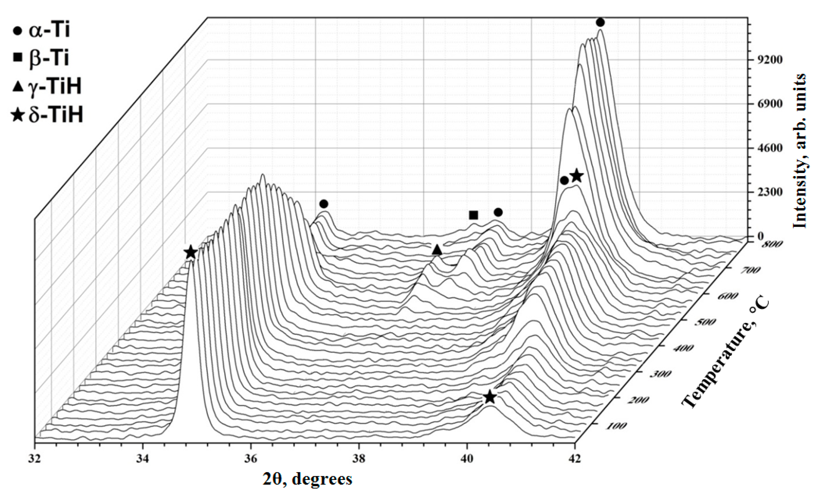
3.3. Phase Transformations and Structure Evolution of the Electron Beam Melted Titanium Ti-6Al-4V Alloy

Structural and phase changes in the electron beam melted (EBM) titanium Ti-6Al-4V alloy were investigated on the developed diffraction complex under hydrogenation at 650 °C and hydrogen pressure of 0.5 atm. The results are presented in Figure 14.
In the first 10 min of hydrogenation, the position of the α titanium phase reflections did not significantly change, while the reflections belonging to the β titanium phase are shifted towards smaller angles. It is known that the solubility of hydrogen in the α phase is negligible compared to the β phase [40]. Moreover, hydrogen is able to reduce the temperature of the polymorphic α → β transformation, thereby stabilizing the β phase in the alloy [32]. Subsequent hydrogenation up to 30 min leads to a decrease in the intensity of the α phase reflections and an increase in the intensity of the β phase, which indicate an increase in the β phase volume content.
The β phase content continued to increase while the α → α2 phase transformation occurs after 30 min of hydrogenation. The latter can be caused due to redistribution of alloying elements in α + β titanium alloys under the action of hydrogen, which results in Al enrichment of β titanium phase. It is known that hydrogen predominantly accumulates in areas with high concentration of tensile stresses [41]. The hydrogen accumulation can result in weakening of metal ion bonds in the lattice [42]. Apparently, the metal bonds are weakened due to electron transfer to the 3d sublevel of the metal. Significant diffusion of alloying elements in Ti-6Al-4V alloy was observed under hydrogenation up to 0.4 wt.% in Reference [43]. Hydrogen solid solution causes lattices distortions in α and β phases of titanium alloys resulting in elastic stresses development. Relaxation of such stresses can influence on distribution of dislocations, which leads to large number of subgrain boundaries. Taking into account that the temperature of hydrogenation is 650 °C, it is expected that the alloying atoms especially Al may segregate at grain boundaries. Therefore, the α2 phase based on Ti3Al may be formed at the grain boundaries. Similar transformations have been also experimentally observed by Sun et al. [44], where the titanium Ti-6Al-4V alloy was hydrogenated at 650 °C.

4. Conclusions

This work is devoted to the development and testing of the X-ray diffraction complex for investigation of the structural-phase changes in materials during dynamic processes in a gaseous atmosphere. The achieved characteristics of the complex make it possible to obtain diffraction patterns with high resolution and accuracy significantly exceeding serial laboratory diffractometers.
The main conclusions are the following:
(1) In situ diffraction complex has been developed for investigations of structural and phase changes in polycrystalline materials under conditions of a gas atmosphere and elevated temperature with the following characteristics: time resolution—1 min; angle resolution—0.0143°; temperature range—25–2300 °C; inert (helium, argon, nitrogen) and aggressive (hydrogen, oxygen) gaseous.
(2) The developed complex was tested on a commercially pure titanium powder in the processes of linear heating, gas-phase hydrogenation at a temperature of 500 °C and a hydrogen pressure of 0.5 atm, as well as a thermally stimulated hydrogen release in the temperature range 30–800 °C.
(3) It was revealed that hydrogenation of commercially pure titanium leads to the formation of an intermediate phase of metastable γ titanium hydride with the lifetime 35–40 min. The γ titanium hydride phase is also formed upon the hydrogen release under heating above 450 °C from stable δ titanium hydride. An increase in temperature to 650 °C leads to the decomposition of γ hydride phase.
(4) It was found that hydrogenation of Zr-1Nb alloy at a hydrogen pressure of 0.5 atm is accompanied by the transformation of the α phase into a stable δ hydride, which rate of formation increases by 2 times with increasing temperature from 350 °C to 450 °C.
(5) It is shown that the β phase and the α2 phase based on Ti3Al intermetallic compound are formed under hydrogenation of the EBM Ti-6Al-4V alloy at a temperature of 650 °C and a hydrogen pressure of 0.5 atm up to 0.6 wt.%. The α → α + β → β + α2 phase transformations is observed.

Author Contributions

M.S. and G.G. developed X-ray complex and conducted XRD measurements. E.K. performed SEM measurements. N.P. manufactured all samples including EBM and prepared the manuscript according the guidelines. V.K. and T.M. carried out hydrogen absorption curves analysis. All authors analyzed results and wrote the text of the manuscript. All authors have read and agreed to the published version of the manuscript.

Funding

This research was funded by the Russian Science Foundation, research project No. 17-79-20100.

Acknowledgments

This work was carried out within the framework of the Competitiveness Enhancement Program of National Research Tomsk Polytechnic University.

Conflicts of Interest

The authors declare no conflict of interest.

References

  1. Li, C.Y.; Yu, Z.H.; Liu, H.Z.; Lü, T.Q. High pressure and high temperature in situ X-ray diffraction study on the structural stability of tantalum disilicide. Solid State Commun. 2013, 157, 1–5. [Google Scholar] [CrossRef]
  2. Anis, S.F.; Hashaikeh, R.; Hilal, N. Functional materials in desalination: A review. Desalination 2019, 468, 114077. [Google Scholar] [CrossRef]
  3. Grabovetskaya, G.P.; Stepanova, E.N.; Dubrovskaya, A.S. Effect of hydrogen on the creep of the ultrafine-grained zirconium Zr–1Nb alloy at 673 K. Int. J. Hydrogen Energy 2017, 42, 22633–22640. [Google Scholar] [CrossRef]
  4. Tang, D.; Hao, L.; Li, Y.; Li, Z.; Dadbakhsh, S. Dual gradient direct ink writing for formation of kaolinite ceramic functionally graded materials. J. Alloys Compd. 2019, 814, 152275. [Google Scholar] [CrossRef]
  5. Bordulev, I.; Kudiiarov, V.; Svyatkin, L.; Syrtanov, M.; Stepanova, E.; Čížek, J.; Vlček, M.; Li, K.; Laptev, R.; Lider, A. Positron annihilation spectroscopy study of defects in hydrogen loaded Zr-1Nb alloy. J. Alloys Compd. 2019, 798, 685–694. [Google Scholar] [CrossRef]
  6. Shmakov, A.N.; Cherepanova, S.V.; Zyuzin, D.A.; Fedorova, Y.; Bobrikov, I.; Roger, A.-C.; Adamski, A.; Sadykov, V. The crystal structure of compositionally homogeneous mixed ceria-zirconia oxides by high resolution X-ray and neutron diffraction methods. Open Chem. 2017, 15, 438–445. [Google Scholar] [CrossRef] [Green Version]
  7. Bösenberg, U.; Pistidda, C.; Tolkiehn, M.; Busch, N.; Saldan, I.; Suarez-Alcantara, K.; Arendarska, A.; Klassen, T.; Dornheim, M. Characterization of metal hydrides by in-situ XRD. Int. J. Hydrogen Energy 2014, 39, 9899–9903. [Google Scholar] [CrossRef] [Green Version]
  8. Gong, Z.; Yang, Y. The application of synchrotron X-ray techniques to the study of rechargeable batteries. J. Energy Chem. 2018, 27, 1566–1583. [Google Scholar] [CrossRef] [Green Version]
  9. Boldyrev, V.V.; Gaponov, Y.A.; Lyakhov, N.Z.; Politov, A.A.; Tolochko, B.P.; Shakhtshneider, T.P.; Sheromov, M.A. Experience in use of synchrotron radiation in solid state chemistry studies. Nucl. Instrum. Methods Phys. Res. Sect. A 1987, 261, 192–199. [Google Scholar] [CrossRef]
  10. Bilgin, G.M.; Esen, Z.; Akın, Ş.K.; Dericioglu, A.F. Optimization of the mechanical properties of Ti-6Al-4V alloy fabricated by selective laser melting using thermohydrogen processes. Mater. Sci. Eng. A 2017, 700, 574–582. [Google Scholar] [CrossRef]
  11. Shen, C.C.; Perng, T.P. Pressure–composition isotherms and reversible hydrogen-induced phase transformations in Ti–6Al–4V. Acta Mater. 2007, 55, 1053–1058. [Google Scholar] [CrossRef]
  12. Cheng, H.; Lu, C.; Liu, J.; Yan, Y.; Han, X.; Jin, H.; Wang, Y.; Liu, Y.; Wu, C. Synchrotron radiation X-ray powder diffraction techniques applied in hydrogen storage materials-A review. Prog. Nat. Sci. Mater. Int. 2017, 27, 66–73. [Google Scholar] [CrossRef]
  13. Majuste, D.; Ciminelli, V.S.T.; Eng, P.J.; Osseo–Asare, K. Applications of in situ synchrotron XRD in hydrometallurgy: Literature review and investigation of chalcopyrite dissolution. Hydrometallurgy 2013, 131, 54–66. [Google Scholar] [CrossRef]
  14. Krysina, O.V.; Koval, N.N.; Smakov, A.N.; Vinokurov, Z.S. In situ X-ray investigation of coatings based on titanium nitride upon high-temperature oxidation in air. J. Surf. Inv. 2016, 10, 1067–1071. [Google Scholar] [CrossRef]
  15. Craievich, A.F. Synchrotron radiation in Brazil. Past, present and future. Radiat. Phys. Chem. 2019, 167, 108253. [Google Scholar] [CrossRef]
  16. Mastrogiacomo, M.; Campi, G.; Cancedda, R.; Cedola, A. Synchrotron radiation techniques boost the research in bone tissue engineering. Acta Biomater. 2019, 89, 33–46. [Google Scholar] [CrossRef] [PubMed]
  17. Lo, B.T.W.; Ye, L.; Tsang, S.C.E. The Contribution of Synchrotron X-Ray Powder Diffraction to Modern Zeolite Applications: A Mini-review and Prospects. Chem 2018, 4, 1778–1808. [Google Scholar] [CrossRef]
  18. Xu, W.; Liu, Y.; Marcelli, A.; Shang, P.P.; Liu, W.S. The complexity of thermoelectric materials: Why we need powerful and brilliant synchrotron radiation sources? Mater. Today Phys. 2018, 6, 68–82. [Google Scholar] [CrossRef]
  19. Venediktova, O.S.; Bulavchenko, O.A.; Tsyrulnikov, P.G.; Afonasenko, T.N.; Vinokurov, Z.S.; Tsybulya, S.V. High-Temperature X-Ray Diffraction Investigation of the Decomposition Process in Manganese-Gallium Spinel Mn1.5Ga1.5O4. J. Struct. Chem. 2018, 59, 370–376. [Google Scholar] [CrossRef]
  20. Murashkina, T.L.; Syrtanov, M.S.; Laptev, R.S.; Stepanova, E.N.; Lider, A.M. Structure and defects evolution at temperature and activation treatments of the TiCr2 intermetallic compound of Laves phase C36-type. Int. J. Hydrogen Energy 2019, 44, 10732–10743. [Google Scholar] [CrossRef]
  21. Stepanova, E.; Pushilina, N.; Syrtanov, M.; Laptev, R.; Kashkarov, E. Hydrogen effect on Ti-6.5Al-3.5Mo-1.5Zr-0.3Si parts produced by electron beam melting. Int. J. Hydrogen Energy 2019, 44, 29380–29388. [Google Scholar] [CrossRef]
  22. Kriegner, D.; Matěj, Z.; Kužel, R.; Holý, V. Powder diffraction in Bragg–Brentano geometry with straight linear detectors. J. Appl. Crystallogr. 2015, 48, 613–618. [Google Scholar] [CrossRef] [PubMed] [Green Version]
  23. Skarzynski, T. Collecting data in the home laboratory: Evolution of X-ray sources, detectors and working practices. Acta Crystallogr. Sect. D Biol. Crystallogr. 2013, 69, 1283–1288. [Google Scholar] [CrossRef] [PubMed] [Green Version]
  24. Bruker LYNXEYE XE 1D Detector. Available online: http://www.bruker.com (accessed on 24 March 2020).
  25. Ohbuchi, A. Applications of the two-dimensional detector HyPix-3000 in X-ray diffractometry. Rigaku J. 2015, 31, 4. [Google Scholar]
  26. Shiramata, Y. Micro-area X-ray diffraction measurement by SmartLab μHR diffractometer system with ultra-high brilliance microfocus X-ray optics and two-dimensional detector HyPix-3000. Rigaku J. 2016, 32, 1. [Google Scholar]
  27. OneSight Wide-Range High-Speed Detector, Shimadzu. Available online: http://www.shimadzu.com (accessed on 24 March 2020).
  28. ASTM A. F2924-14, Standard Specification for Additive Manufacturing Titanium-6 Aluminum-4 Vanadium with Powder Bed Fusion; ASTM Standards: West Conshohocken, PA, USA, 2014; p. 10.
  29. Voskuilen, T.; Zheng, Y.; Pourpoint, T. Development of a Sievert apparatus for characterization of high pressure hydrogen sorption materials. Int. J. Hydrogen Energy 2010, 35, 10387–10395. [Google Scholar] [CrossRef]
  30. Souvatzis, P.; Eriksson, O.; Katsnelson, M.I. Anomalous thermal expansion in α-titanium. Phys. Rev. Lett. 2007, 99, 015901. [Google Scholar] [CrossRef] [Green Version]
  31. Wang, C.; Zhang, Y.; Wei, Y.; Mei, L.; Xiao, S.; Chen, Y. XPS study of the deoxidization behavior of hydrogen in TiH2 powders. Powder Technol. 2016, 302, 423–425. [Google Scholar] [CrossRef]
  32. Matysina, Z.A.; Shchur, D.V. Phase Transformations α→β→γ→δ→ ε in Titanium Hydride TiHx with Increase in Hydrogen Concentration. Russ. Phys. J. 2001, 44, 1237–1243. [Google Scholar] [CrossRef]
  33. Kudiiarov, V.N.; Kashkarov, E.B.; Syrtanov, M.S.; Lider, A.M. Hydrogen sorption by Ni-coated titanium alloy VT1-0. Int. J. Hydrogen Energy 2017, 42, 10604–10610. [Google Scholar] [CrossRef]
  34. Kudiiarov, V.N.; Syrtanov, M.S.; Bordulev, Y.S.; Babikhina, M.N.; Lider, A.M.; Gubin, V.E.; Murashkina, T.L. The hydrogen sorption and desorption behavior in spherical powder of pure titanium used for additive manufacturing. Int. J. Hydrogen Energy 2017, 42, 15283–15289. [Google Scholar] [CrossRef]
  35. Ma, M.; Wang, L.; Tang, B.; Lyu, P.; Xiang, W.; Wang, Y.; Tan, X. Kinetics of hydrogen desorption from titanium hydride under isothermal conditions. Int. J. Hydrogen Energy 2018, 43, 1577–1586. [Google Scholar] [CrossRef]
  36. Novikova, S.I. Thermal expansion. Semicond. Semimet. 1966, 2, 33–48. [Google Scholar] [CrossRef]
  37. Christensen, M.; Wolf, W.; Freeman, C.; Wimmer, E.; Adamson, R.B.; Hallstadius, L.; Cantonwined, P.E.; Madere, E.V. Diffusion of point defects, nucleation of dislocation loops, and effect of hydrogen in hcp-Zr: Ab initio and classical simulations. J. Nucl. Mater. 2015, 460, 82–96. [Google Scholar] [CrossRef]
  38. Syrtanov, M.S.; Kudiiarov, V.N.; Kashkarov, E.B.; Shmakov, A.N.; Vinokurov, Z.S.; Babikhina, M.N.; Zolotarev, K.V. Application of Synchrotron Radiation for in Situ XRD Investigation of Zirconium Hydrides Formation at Gas-phase Hydrogenation. Phys. Procedia 2016, 84, 342–348. [Google Scholar] [CrossRef]
  39. Pushilina, N.S.; Lider, A.M.; Kudiiarov, V.N.; Chernov, I.P.; Ivanova, S.V. Hydrogen effect on zirconium alloy surface treated by pulsed electron beam. J. Nucl. Mater. 2015, 456, 311–315. [Google Scholar] [CrossRef] [Green Version]
  40. Zhu, T.; Li, M. Effect of 0.770 wt% H addition on the microstructure of Ti–6Al–4V alloy and mechanism of δ hydride formation. J. Alloys Compd. 2009, 481, 480–485. [Google Scholar] [CrossRef]
  41. Yan, M.; Yu, P. An Overview of Densification, Microstructure and Mechanical Property of Additively Manufactured Ti-6Al-4V–Comparison among Selective Laser Melting, Electron Beam Melting, Laser Metal Deposition and Selective Laser Sintering, and with Conventional Powder; Sinter. Tech. Mater.; IntechOpen: London, UK, 2015; pp. 77–106. [Google Scholar] [CrossRef]
  42. Johnson, H.H.; Morlet, J.G.; Troiano, A.R. Hydrogen, crack initiation, and delayed failure in steel. Trans. Met. Soc. AIME 1958, 212, 528–536. [Google Scholar]
  43. Liu, H.; Cao, J.; He, P.; Feng, J.C. Effect of hydrogen on diffusion bonding of commercially pure titanium and hydrogenated Ti6Al4V alloys. Int. J. Hydrogen Energy 2009, 34, 1108–1113. [Google Scholar] [CrossRef]
  44. Sun, P.; Fang, Z.Z.; Koopman, M.; Paramore, J.; Chandran, K.R.; Ren, Y.; Lu, J. An experimental study of the (Ti–6Al–4V)–xH phase diagram using in situ synchrotron XRD and TGA/DSC techniques. Acta Mater. 2015, 84, 29–41. [Google Scholar] [CrossRef] [Green Version]
Figure 1. Schematic diagram of the designed complex: 1—inert (argon, helium) gas cylinder; 2—hydrogen generator; 3—gas mixer; 4—gas storage chamber; 5—high temperature attachment; 6—vacuum system; 7,8—pressure sensors; 9—pressure regulator; 10–15—control valves.
Metals 10 00447 g001
Figure 2. Scanning electron microscope (SEM) image of the CP-Ti.
Metals 10 00447 g002
Figure 3. Diffraction patterns of the CP-Ti in the process of linear heating from RT to 500 °C.
Metals 10 00447 g003
Figure 4. Dependence between lattice parameters and temperature of the CP-Ti powder.
Metals 10 00447 g004
Figure 5. In situ phase transformations of the CP-Ti under hydrogenation at the temperature of 500 °C and constant hydrogen pressure of 0.5 atm.
Metals 10 00447 g005
Figure 6. Kinetic curves of hydrogen absorption of the CP-Ti at a temperature of 500 °C and hydrogen pressure of 0.5 atm.
Metals 10 00447 g006
Figure 7. Diffraction patterns of the CP-Ti in the process of a linear cooling from 500 °C to room temperature (RT).
Metals 10 00447 g007
Figure 8. Diffraction patterns of the CP-Ti in the process of the hydrogen desorption under heating from RT to 800 °C.
Metals 10 00447 g008
Figure 9. Diffraction patterns of the Zr-1Nb alloy with nickel coating in the process of heating to a temperature of 350 °C.
Metals 10 00447 g009
Figure 10. Dependence between nickel lattice parameter and temperature.
Metals 10 00447 g010
Figure 11. Diffraction patterns of the Zr-1Nb with nickel coating under gas phase hydrogenation at a temperature of 350 °C.
Metals 10 00447 g011
Figure 12. Diffraction patterns of the Zr–1Nb with nickel coating under gas phase hydrogenation at a temperature of 450 °C.
Metals 10 00447 g012
Figure 13. Hydrogen sorption curves of the Zr-1Nb with nickel coating at temperatures of 350 °C (a) and 450 °C (b).
Metals 10 00447 g013
Figure 14. Diffraction patterns of the electron beam melted (EBM) titanium Ti-6Al-4V alloy under gas phase hydrogenation at a temperature of 650 °C and hydrogen pressure of 0.5 atm.
Metals 10 00447 g014
Table 1. Technical specifications of the OneSight high-speed detector.
ModelFD-1001
Sensitive elementLine of reverse biased p-n junctions
Detection principleSingle photon count
Number of channels1280
Active area64 × 8 mm2
Strip width50 μm
Energy range5–30 keV
Coolingnot required
Weight280 g
One shot modeyes
Angle resolutionDimensions0.0143°W 72 mm × H 100 mm × D 24 mm
Table 2. Technical specifications of DualTrans MicroPirani/Absolute Piezo 910 pressure sensors.
Sensitive ElementMicroPirani (MEMS Thermal Conductivity)
Piezo Absolute (MEMS diaphragm)
Measuring Range(1 × 10⁻⁵ ÷ 1500) Torr
GaseousAir, Argon, Helium, Nitrogen, H2, H2O vapor, CO2, Xenon, Neon
Operating Temperature Range0–40 °C
Digital CommunicationRS485/RS232 (4800 to 230,400 Baud)
Analog Output (Absolute Pressure)1 to 9.2 VDC, 1 VDC/decade, 100 Ω maximum output impedance
Analog Output Resolution16-bit
Relay Response100 ms maximum
Power Requirements9 to 30 VDC, <1.2 watts max
Accuracy5 × 10−4 to 1 × 10⁻³ Torr ±10% of reading
10−3 to 11 Torr ±5% of reading
11 to 1000 Torr ±0.75% of reading
Repeatability5 × 10−4 to 10−3 Torr ±8% of reading
10−3 Torr to 11 Torr ±2% of reading
11 to 1000 Torr ±0.2% of reading
Overpressure Limit2250 Torr (Absolute)
Weight170 g

