Article

Effect of Thermal Ageing at 400 °C on the Microstructure of Ferrite-Austenite Interface of Nickel-Base Alloy Narrow-Gap Dissimilar Metal Weld

1
VTT Technical Research Centre of Finland LTD, Kemistintie 3, 02150 Espoo, Finland
2
Department of Mechanical Engineering, Aalto University School of Engineering, Otakaari 4, 02150 Espoo, Finland
*
Author to whom correspondence should be addressed.
Metals 2020, 10(3), 421; https://doi.org/10.3390/met10030421
Submission received: 4 March 2020 / Revised: 21 March 2020 / Accepted: 22 March 2020 / Published: 24 March 2020

Abstract

:
Dissimilar metal welds (DMWs) are a key design feature in nuclear power systems, typically involving ferritic low-alloy steels (LAS), stainless steels (SS), and nickel-base alloys. They are, however, a potential concern regarding the structural integrity of nuclear power systems. In particular, the LAS/nickel-base alloy weld metal interface is known to develop a local strength mismatch upon post-weld heat treatment (PWHT). Very limited data is available on the effect of thermal ageing on the DMW interface. The aim of this study was to investigate the effects of thermal ageing at 400 °C for up to 10,000 h on a narrow-gap DMW mock-up representative of the weld between the reactor pressure vessel nozzle and its safe-end after PWHT, with a special focus on the LAS SA 508/nickel-base Alloy 52 weld metal interface. No significant effect of thermal ageing on the appearing microstructure was observed in either LAS base material, LAS heat-affected zone or Alloy 52 weld metal. However, thermal ageing reduced the local strength mismatch at the LAS/nickel-base weld metal interface formed during PWHT. The reduction of the strength mismatch was detected using nanoindentation measurements and was concluded to be associated with a decrease in the carbon pile-up in the weld metal caused by PWHT. Based on the obtained results, thermal ageing promotes carbon diffusion from the weld metal side of the fusion boundary further away into the weld metal and thus slightly decreases the local strength mismatch.

1. Introduction

With the exception of fuel cladding materials, the main materials used in the components and piping of primary circuits of pressurized water reactors (PWRs) are ferritic low-alloy steels (LAS), stainless steels (SS), and nickel-base alloys [1]. LAS alloyed with low contents of chromium, nickel, molybdenum, and vanadium can lead to a good combination of high strength and ductility, which are used in structural components like a reactor pressure vessel (RPV) [2]. Austenitic SS are utilized for structural materials (types 304, 304L, 316, and 316L) and as corrosion-resistant cladding of the RPV and pressurizer (types 308 and 309). Nickel-base alloys are applied for high-strength components, some critical applications, and welds. Dissimilar metal welds (DMWs), where materials of different composition and crystal structure are joined, reveal a combination of all the above-mentioned types of materials. From the design and performance point of view, DMWs are critical and they have been related to a number of incidents involving intergranular stress corrosion cracking (IGSCC) [2,3,4], with sensitized microstructures found in SS and nickel-base alloy safe-ends and within weld metals [5,6]. Nickel-base weld metals such as Alloys 182 and 82, based on the composition of wrought Alloy 600, have increased the service life of DMWs by reducing carbon migration at the interface and differential expansion strains [7]. They are, however, susceptible to IGSCC. Cracking incidents, involving Alloys 600 and 182 in RPV safe-ends and head penetrations as well as steam generators, have been observed in many plants due to the presence of corrosive environment, high temperature, residual stresses, and material sensitization effects [2,3,8]. IGSCC in high-temperature, high-purity PWR water is specifically noted as Primary Water Stress Corrosion Cracking (PWSCC) [9,10,11]. In safe-end weld cracking incidents, crack propagation along the DMW interface is often limited to the weld metal [12] and the cracks grow normally in the axial orientation [13]. An increasing susceptibility to stress corrosion cracking (SCC) in terms of ductility loss has been observed particularly at the weld interface region [14]. SCC and corrosion fatigue of DMW interfaces are therefore the major concerns for the nuclear industry.
The transition zones of the DMW interfaces are usually classified as the heat-affected zone (HAZ), the partially-melted zone (PMZ), and the unmixed zone (UMZ) [15]. Residual stresses and strains are well-known SCC accelerants. The distribution of the residual strains at the weld interface can be as high as 40–50% in the weld metal, 20% in the UMZ and PMZ, 15% in the base material HAZ and 8–10% within the base material [16].
A typical example of DMW is the RPV nozzle to safe-end weld between the SS-cladded RPV ferritic LAS and the austenitic SS pipe, using a nickel-base filler metal. A significant composition gradient, especially regarding the carbon and chromium contents, forms at the interface and a complex microstructure is present resulting from the diffusion of alloying elements, notably carbon [17]. The reduced chromium and nickel contents in the transition region due to the dilution effects are assumed to increase the SCC susceptibility [18]. The formation of hard and soft layers, driven by the composition gradients, leads to a low-strength area in the carbon-depleted zone (CDZ) and increases the strength mismatch at the interface [19,20]. The complex DMW interface region consists of different microstructural regions [21,22,23,24]. Key microstructural features, which can be found near the weld interface, include CDZ [25], martensite [26], carbon build-up [27], and Type II boundaries [14,28,29].
In order to improve the SCC resistance, Alloy 600 has been replaced by Alloy 690 in steam generator tubes and vessel head penetration tubes. The filler metals Alloy 52, 152, and 52M were developed based on the composition of Alloy 690 and are nowadays used in DMWs. Due to the higher chromium content, they show a better SCC resistance than Alloys 182 and 82, with remarkable improvement in terms of crack initiation time and SCC crack growth rate [30]. However, the thermal stability of Alloy 690 in the long-term operation of nuclear power plants (60–80 years), remains a crucial topic of research [31]. The susceptibility of welds to SCC depends not only on the properties of the base and weld metals, but also on the microstructural changes occurring at the interface during welding and post-weld heat treatment (PWHT) [32,33]. In particular, there is still little knowledge on the long-term behavior of these interfaces since no in-service experience is available, yet. The aim of this study is therefore to characterize the microstructural changes occurring at the RPV nozzle to safe-end ferrite/austenite interface upon thermal ageing.

2. Experimental Methods and Materials

Two narrow-gap DMW mock-ups with RPV nozzle to safe-end weld were investigated in this study. One laboratory RPV safe-end weld mock-up plate was made at Aalto University and it was studied in as-welded (AW) and in PWHT condition. The PWHT was performed at 550 ± 15 °C for 17 h followed at 610 ± 15 °C for 7 h. An industrial RPV safe-end weld mock-up, fully representative as an actual component, was manufactured by Mitsubishi Heavy Industries Ltd. with a similar PWHT. It was studied in the as-received (AR) condition and after thermal ageing for 5000 h and 10,000 h at 400 °C. Both mock-ups are representative of the RPV safe-end of a modern PWR design, using the narrow-gap welding technique without a buttering layer between the LAS and the weld metal (see Figure 1). Ageing at 400 °C for 10,000 h was estimated to correspond to 60 years of operation at PWR in-service temperatures in terms of grain boundary (GB) segregation of phosphorous in the RPV LAS [34]. The weld mock-ups consisted of SA 508 and AISI 316L base materials, SS 308L/309L cladding on the RPV side, and Alloy 52 weld metal in both cases (see Table 1 for chemical compositions). Since the first DMW mock-up made at Aalto University was studied within the SINI project, and the second DMW mock-up was studied within the NIWEL project, the five conditions are called “SINI AW” (as-welded), “SINI PWHT” (post-weld heat treated), “NIWEL AR” (as-received, i.e. post-weld heat treated), “NIWEL 5000 h” (5000 h aged at 400 °C) and “NIWEL 10,000 h” (10,000 h aged at 400 °C). NIWEL mock-up was received in the PWHT condition and thus could not be studied in the AW condition.
Samples from the LAS base material, HAZ, PMZ, UMZ and the weld metal, respectively, were prepared by electrical discharge machining (EDM). Samples were ground with Struers SiC grinding papers up to 4000 grit and then polished with 3 μm, 1 μm, and 0.25 μm Struers DiaPro diamond dispersions. Final polishing with vibratory polishing in colloidal silica alkaline suspension removed the last deformation layers from grinding. Optical microscopy (OM) and scanning electron microscopy (SEM) were used to characterize the microstructures. Electron backscatter diffraction (EBSD) was applied for grain size measurement with a step size of 60 nm. Energy dispersive X-ray spectroscopy (EDS) was utilized to characterize the composition gradients at the weld interface with 10 keV accelerating voltage. Instrumented microhardness and nanoindentation measurements were carried out to study the hardness profiles across the LAS HAZ and the weld interface. Microhardness measurements were done with a Vickers tip using an indentation load of 350 mN and a step size of 50 µm (pause: 10 s and loading rate: 750 mN/min), while nanoindentation measurements were performed with a Berkovich tip using an indentation load of 1.5 mN and a step size of 5 µm (pause: 10 s and loading rate: 7.5 mN/min). In addition, HV0.5 was used for microhardness measurement with the indentation weight of 500 g on the reference state. Otherwise, HVIT is used in this work to describe the hardness value both from microhardness and nanoindentation measurements but with a different physical meaning. In all figures and hardness profiles, the LAS is shown on the left and Alloy 52 weld metal on the right, with the fusion boundary (FB) at the X = 0 position on the x-axis.

3. Results

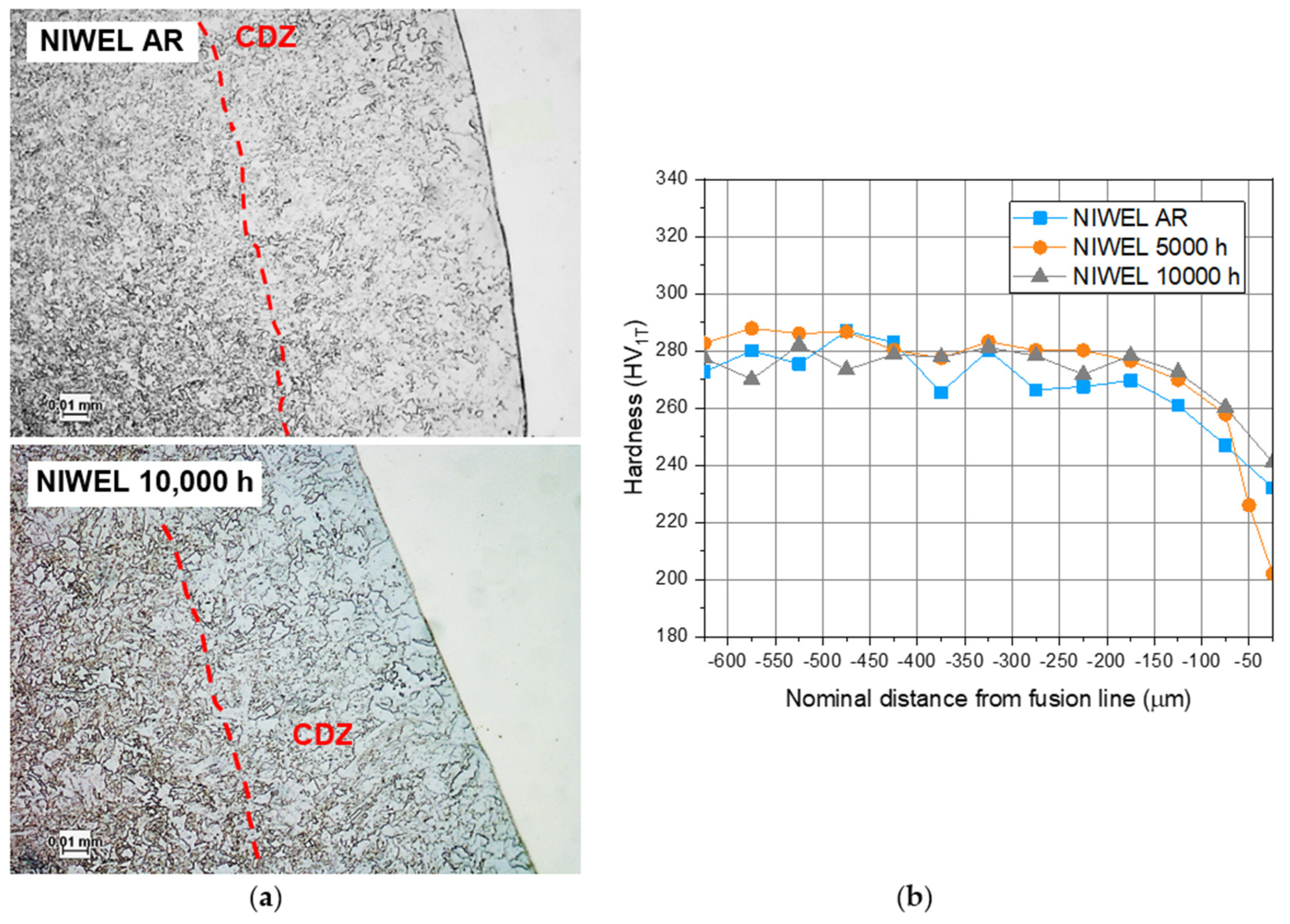
3.1. Heat-Affected Zone of the LAS

As shown in Figure 2, the LAS HAZ extends about 2.5 mm from the FB to the base material (Figure 2a). The LAS base material, exhibiting a typical level of hardness for LAS (240 HV0.5) consists of coarse ferrite grains with a tempered upper bainite microstructure (Figure 2b). The microstructure refines progressively towards the FB due to the heat input from the welding process (Figure 2c). An intermediate zone is found in the HAZ with partially refined grains, followed by a grain-refined zone of higher hardness (about 280 HV0.5). Adjacent to the FB, a layer of coarse grains is present resulting from the higher heat, where carbon has diffused to the low-carbon/high-chromium nickel-base weld metal side of the interface (Figure 2d). This layer is called CDZ and it exhibits the lowest hardness (about 230 HV0.5). To be noted is the presence of darker or lighter bands in the LAS HAZ (see Figure 2a). The darker bands have a relatively smaller grain size and are slightly harder (about 300 HV0.5) than the rest of the HAZ.
EBSD maps of NIWEL 5000 h in Figure 3 reveal the progressive grain refining from 2500 to 300 µm distances from the interface, and the grain coarsening near the FB. The grain size in the LAS changes from about 2.5 µm in the base material to about 1.5 µm in the grain-refined zone and back to 2.5 µm in the CDZ. Hardness is affected by the accommodation of strain in the area of contact under the indenter tip and therefore by the sub-grain size which is reported in this paper with EBSD. No significant changes in the grain size due to thermal ageing were observed when comparing the AR and aged NIWEL DMW mock-up samples. Figure 4 shows a comparison of the precipitates in NIWEL AR and NIWEL 10,000 h at increasing distances from the FB. No changes in carbide precipitation were thus observed upon thermal ageing. As seen in Figure 5, the hardness profile across the LAS HAZ is clearly affected by the grain size. Since the thermal ageing at 400 °C for 10,000 h does not affect the grain size or carbide precipitation, there are no changes in the hardness level either.

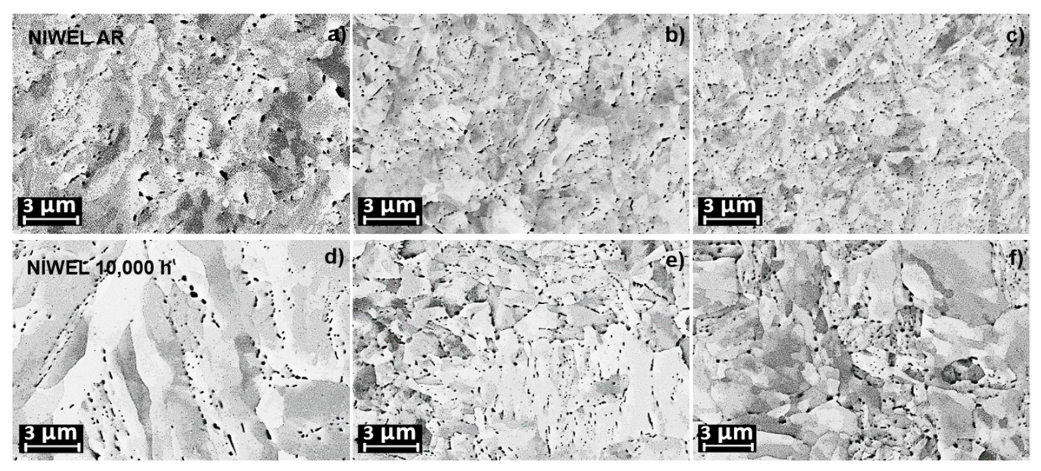
3.2. Alloy 52 Weld Metal

Microhardness measurements were carried out with 350 mN load in the Alloy 52 weld metal of the NIWEL DMW before and after ageing at 400 °C for 10,000 h. The results are shown in Table 2. The hardness of the weld metal increases from the weld crown (about 240 HVIT) to the weld root (about 270 HVIT), with no observed influence of thermal ageing. Scatter in the results was attributed mostly to the heterogeneous microstructure of the weld metal and the difficulty to make measurements from exactly the same locations.
As illustrated in Figure 6, showing GBs in Alloy 52 weld metal before and after thermal ageing for 10,000 h at 400 °C, the thermal ageing does not have a visible effect on the microstructure of the weld metal. There is therefore no significant influence of the thermal ageing at 400 °C for up to 10,000 h on the microstructure and hardness levels of Alloy 52 weld metal (excluding the FB region) of the NIWEL DMW mock-up.

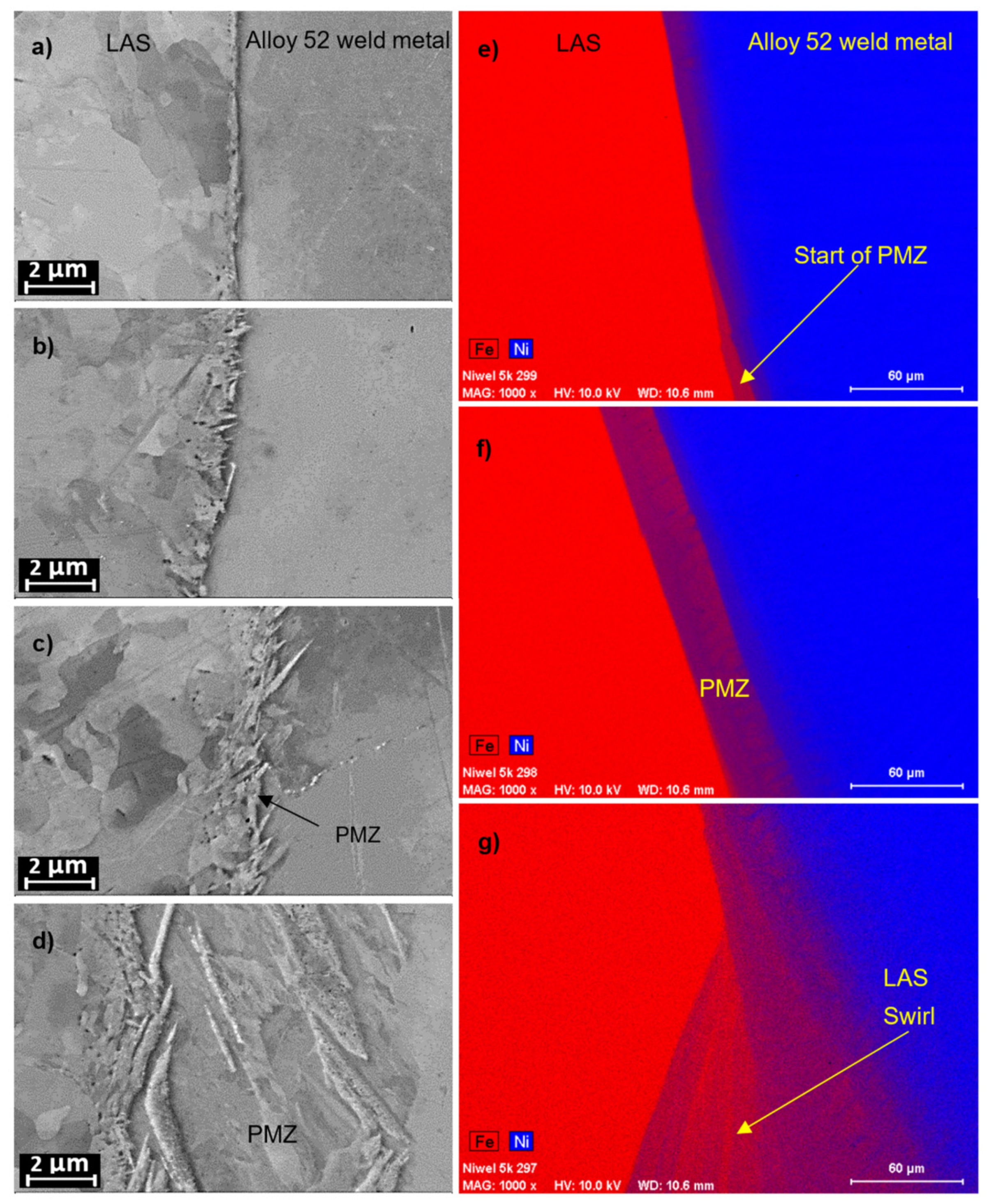
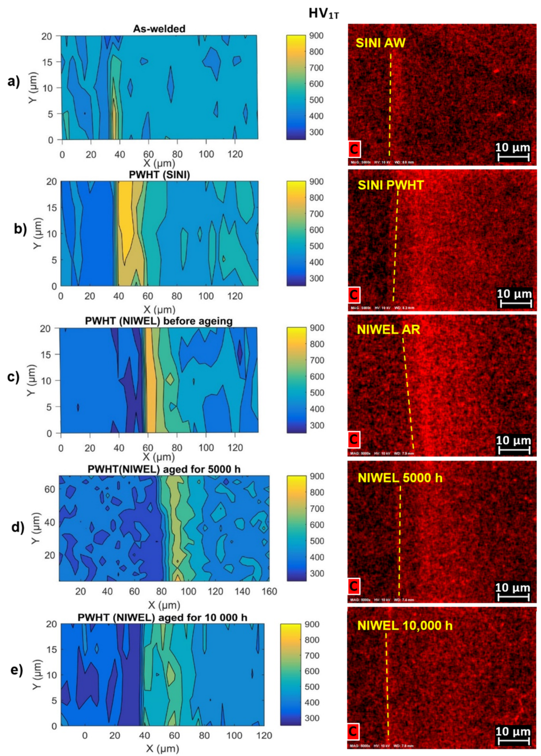
3.3. Ferrite/Austenite Interface

As seen in Figure 7, the FB changes from a rather straight line to a feathery layer with a width of more than 10 µm. This layer consists of a mixture of fine body-centered cubic (bcc) grains from the LAS and face-centered cubic (fcc) structure from the weld metal. It is much harder (about 650 HVIT) than the materials around it (less than 300 HVIT for the LAS or Alloy 52). The evolution of the PMZ layer follows the structure of the weld passes. Starting from a straight FB, the PMZ grows larger as the weld pass enters the solidified weld metal and is finally swiped into the weld metal to form a swirl of hard bcc structure in the austenitic weld metal. In addition, the iron content increases with the weld pass, not only due to the PMZ but also due to the dilution of iron in the transition zone between two successive weld passes. These characteristics were found in all conditions of the DMWs.
When studying the effect of thermal ageing on the transition zones, it is necessary to understand the prior effect of PWHT. PWHT is a standard procedure to temper welds after the welding process, but a clear side effect is seen in Figure 8, which shows the difference in the CDZ width between SINI AW (about 10 µm wide) and SINI PWHT (more than 50 µm wide). The corresponding hardness profiles indicate the widening of the CDZ due to PWHT, as a stronger decrease of hardness is observed at a larger distance away from the fusion line. NIWEL AR exhibits the similar condition as SINI PWHT, as the same standard PWHT was applied for both mock-ups. As seen in Figure 9, the CDZ with a width of about 60–70 µm is present in NIWEL AR. However, subsequent thermal ageing for up to 10,000 h does not appear to influence neither the CDZ width nor the hardness profile (see Figure 9).
As seen in Figure 10, the direct effect of the widening of the CDZ upon PWHT is revealed in the weld metal side of the interface. A carbon-rich layer forms in Alloy 52 weld metal close to the FB in SINI PWHT condition. As expected, the similar carbon-rich layer is found in NIWEL AR material. However, as observed in NIWEL 5000 h and NIWEL 10,000 h samples, thermal ageing results in the progressive decrease of the carbon-rich layer and its shift away from the fusion line. In parallel, thermal ageing clearly enhances the iron diffusion from the LAS to the weld metal.
Figure 11 shows the microhardness profiles of SINI AW and SINI PWHT. A clear effect of PWHT is observed, as the smooth transition from the LAS to Alloy 52 weld metal in as-welded SINI AW becomes a large hardness mismatch at the FB after the PWHT, with the lowest hardness in the LAS (220 HVIT) and a hardness peak in Alloy 52 weld metal adjacent to the fusion line (650 HVIT). The lowest hardness is associated with the CDZ in the LAS side. Nanoindentation with a step size of 5 µm was used to complement the microhardness measurement over the transition layers. A smaller indentation size enables to obtain measurements with a better spatial resolution and characterize, for example, the narrow width of the hard layers and their position as compared to the FB more precisely [35]. Figure 12 shows the results of nanoindentation measurements across the LAS/Alloy 52 weld metal interface before and after PWHT in the SINI DMW. As shown in the microhardness measurement results, PWHT causes the formation of a hardness peak (840 HVIT) in the weld metal side of the FB, with the highest hardness level starting at the FB and extending about 25 µm into the weld metal. The hardness profile of SINI AW does not show a strong mismatch: a hardness peak (667 HVIT) is present at the FB, where the indentations hit the narrow PMZ (<1 µm), but no hard layer is visible in Alloy 52 weld metal.
Figure 13 shows the microhardness profiles of NIWEL DMW before and after thermal ageing for up to 10,000 h at 400 °C. The hardness profile of NIWEL AR is similar to that of SINI PWHT, with a strong hardness mismatch at the interface and a hardness peak in Alloy 52 weld metal close to the FB. The lowest hardness of NIWEL AR is found in the LAS (220–230 HVIT) and the highest hardness in Alloy 52 weld metal (536 HVIT). Thermal ageing affects the hardness profiles, as the hardness peak in Alloy 52 weld metal decreases stepwise upon ageing for 5000 h (377 HVIT) and 10,000 h (331 HVIT). Figure 14 shows the nanoindentation hardness profiles across the interface before and after thermal ageing. In NIWEL AR, a strong hardness peak is present in the weld metal near the interface (858 HVIT) extending over 40 µm before reaching the typical hardness of Alloy 52 weld metal. After ageing at 400 °C for 5000 h, the hardness peak in Alloy 52 weld metal (733 HVIT) decreases and the hard layer is narrower (about 5 µm). Moreover, the hard layer is not adjacent to the FB anymore, but appears about 10 µm away in the weld metal. After 10,000 h, the same trend is observed, with the hardness peak in Alloy 52 weld metal further decreasing (637 HVIT) and moving further into the weld metal (maximum hardness about 20 µm from the FB). The hardness levels in the LAS and Alloy 52 weld metal away from the FB are not influenced by the thermal ageing.

4. Discussion

The microstructural characterization and the hardness measurement results do not reveal a clear effect of thermal ageing after PWHT on the LAS base material, the LAS HAZ or Alloy 52 weld metal when excluding the FB region. The hardness profile of the LAS HAZ is clearly linked to the grain size variations. No influence of thermal ageing at 400 °C for 10,000 h is observed on either the grain size or carbide precipitation. The hardness increases from 200–220 HVIT in the LAS base metal to 280 HVIT in the grain-refined zone about 400–600 µm away from the FB. The hardness and the grain size (2.5 µm) of the grain-coarsening zone is similar to that of the LAS base metal. No clear changes were observed in the nature or amount of precipitation within grains or at GBs in Alloy 52 weld metal. Hardness levels increasing from the crown to the root of the narrow-gap weld, which remained similar before and after ageing. The focus of the discussion is therefore on the changes occurring at the DMW interface, where the effects of PWHT and thermal ageing were notable. Table 3 and Table 4 summarize the results of the nanoindentation hardness measurements in the SINI DMW before and after PWTH and in the NIWEL DMW before and after thermal ageing, respectively.
As seen in Table 3 and Table 4, the hardest zone of the LAS/Alloy 52 weld metal interface is the martensite-like PMZ forming at the FB. Upon PWHT, however, a local strength mismatch is present with the widening of the CDZ of low hardness and the formation of a hardness peak in Alloy 52 weld metal starting from the FB. A similar behavior was observed in the NIWEL weld. Thermal ageing clearly reduces the local strength mismatch, while the position of the decreased hardness peak in Alloy 52 weld metal moves further away from the FB. The hardness peak in Alloy 52 weld metal is related to the formation of a CDZ in the LAS side and the diffusion and pile-up of carbon into the weld metal during PWHT. Therefore, the thermal ageing reduces the hardness peak in the weld metal side resulting from the diffusion of carbon further away into the weld metal. This correlation of hardness and carbon pile-up is clearly visible when comparing the nanoindentation hardness maps to the EDS maps of the carbon content (see Figure 15). Although EDS is not a sensitive method for carbon measurement, it was one available spectroscopic method reasonably good for qualitative analysis, showing that the trend of carbon measured with the EDS corresponds well with the nanoindentation measurement results.
PWHT causing local strength mismatch in the RPV safe-end DMW may be a concern for PWRs. Previous studies on the fracture mechanical behavior of SINI mock-up showed that PWHT caused a significant decrease of fracture resistance in the J-R tests from specimens where the pre-crack location was close to the FB [36]. In the case of SINI PWHT specimens, cracks in J-R tests initiated in LAS close to the FB and tended to propagate only along the soft LAS CDZ. On the contrary, in SINI AW specimens, cracks in J-R tests were occasionally deflected over the FB into the weld metal and back into the LAS, forming a serrated fracture surface [21,36,37]. A serrated type of fracture forms a larger surface area, which requires more energy than the formation of a planar fracture surface with a smaller surface area. The difference in formed fracture surface area may partly explain the higher measured fracture resistance (JQ and J1 mm) of SINI AW.
Based on the observations made for NIWEL AR and NIWEL 10,000 h, it can be assumed that the thermal ageing at 400 °C does not have significant detrimental effects on Alloy 52 weld metal or the LAS base material and HAZ. Instead, the LAS CDZ was found to remain microstructurally stable upon ageing, while the narrow hard layer in Alloy 52 weld metal was found to soften and move further away from the FB, in association with a progressive disappearance of the carbon build-up due to the thermal ageing in the weld metal near the FB. The thermal ageing at 400 °C for 5000 and 10,000 h is therefore considered to be slightly beneficial in the case of the RPV safe-end Alloy 52 narrow-gap DMW, when considering the performance of the DMW in the operation environment (high-temperature PWR water), as it reduces the strength mismatch at the weld interface. It has been shown that thermal ageing has a detrimental effect on impact toughness of the narrow-gap DMW LAS HAZ, but the ductile-to-brittle transition temperature after thermal ageing remains low enough to ensure the safe operation and shut-down of the power plant [37,38,39,40].

5. Conclusions

The influence of thermal ageing after post-weld heat treatment (PWHT) on the microstructures and hardness levels at the interface of a typical ferrite/austenite narrow-gap dissimilar metal weld interface was characterized. The main conclusions drawn from this study are summarized as follows:
  • Thermal ageing of Alloy 52 at 400 °C for up to 10,000 h does not cause any remarkable changes in the microstructure of the weld metal or in the hardness level from the weld crown (lower hardness) to the weld root (higher hardness).
  • Thermal ageing of the low-alloy steel (LAS) base material and heat-affected zone (HAZ) at 400 °C for up to 10,000 h does not lead to noticeable changes. The microstructure of the LAS HAZ is determined by the grain-refined, grain-coarsened, and carbon-depleted zone related to the welding process. A clear correlation was revealed between grain size and hardness variation in the LAS HAZ.
  • The LAS/Alloy 52 weld metal interface was found to be affected by thermal ageing. The local hardness mismatch caused by the carbon migration from the LAS to the weld metal upon PWHT, with carbon pile-up next to the interface leading to a significant hardness peak in the weld metal, was reduced markedly upon thermal ageing. The hardness peak in the weld metal decreased and moved further away from the fusion boundary in association with a shift and attenuation of the carbon-rich layer in the weld metal near the fusion boundary after PWHT.

Author Contributions

Investigation, M.A., R.M., T.S. and S.L.; writing—original draft preparation, M.A.; writing—review and editing, U.E., H.H. and Z.Q.; supervision, U.E., H.H.; project administration, M.A., U.E., H.H. and I.V. All authors have read and agreed to the published version of the manuscript.

Funding

This study was funded by TEKES, grant number 622/31/2015 along with Finnish (Teollisuuden Voima Oyj, Fortum Power and Heat Oy and Fennovoima Oy) and Swedish (Vattenfall AB, Ringhals AB and OKG AB) energy producing industry within the Structural integrity of Ni-base alloy welds (SINI) and Nickel-base alloy welding forum (NIWEL) research projects. The authors wish to express their gratitude for the funding and support of all the participants of the projects. The APC was funded by H.H.

Conflicts of Interest

The authors declare no conflict of interest.

References

  1. Féron, D. Overview of Nuclear Materials and Nuclear Corrosion Science and Engineering. In Nuclear Corrosion Science and Engineering; Woodhead Publishing: Cambridge, UK, 2012; pp. 31–56. [Google Scholar]
  2. MacDonald, D.D.; Cragnolino, G.A. Corrosion of Steam Cycle Materials. In ASME Handbook on Water Technology for Thermal Power Systems; Cohen, P., Ed.; ASME: New York, NY, USA, 1989; pp. 659–1031. [Google Scholar]
  3. Aaltonen, P.; Hänninen, H. Water Chemistry and Behavior of Materials in PWRs and BWRs; IAEA-TECDOC-965; IAEA: Vienna, Austria, 1997; pp. 205–222. [Google Scholar]
  4. Ehrnstén, U. Corrosion and Stress Corrosion Cracking of Austenitic Stainless Steels. In Comprehensive Nuclear Materials; Allen, T.R., Stoller, R.E., Yamanaka, S., Eds.; Elsevier Ltd.: Amsterdam, The Netherlands, 2012; Volume 5, pp. 93–104. [Google Scholar]
  5. Scott, P.M. Environment Assisted Cracking in Austenitic Components. Int. J. Press. Vessel. Pip. 1996, 65, 255–264. [Google Scholar] [CrossRef]
  6. Lu, Z.; Chen, J.; Shoji, T.; Takeda, Y.; Yamazaki, S. Characterization of Microstructure, Local Deformation and Microchemistry in Alloy 690 Heat-Affected Zone and Stress Corrosion Cracking in High Temperature Water. J. Nucl. Mater. 2015, 465, 471–481. [Google Scholar] [CrossRef]
  7. Payne, B.E. Nickel-base Welding Consumables for Dissimilar Metal Welding Applications. Met. Constr. 1969, 1, 79–87. [Google Scholar]
  8. Fyfitch, S. Corrosion and Stress Corrosion Cracking of Ni-Base Alloys; Elsevier Ltd.: Amsterdam, The Netherlands, 2019; Volume 5, pp. 69–92. [Google Scholar]
  9. Scenini, F.; Newman, R.C.; Cottis, R.A.; Jacko, R.J. Alloy Oxidation Studies Related to PWSCC. In Proceedings of the 12th International Conference on Environmental Degradation of Materials in Nuclear Power Systems-Water Reactors, Salt Lake City, Utah, 14–18 August 2005; pp. 891–902. [Google Scholar]
  10. Andresen, P.L.; Hickling, J.; Ahluwalia, K.S.; Wilson, J.A. Effects of PWR Primary Water Chemistry on PWSCC of Ni Alloys. In Proceedings of the 13th International Conference on Environmental Degradation of Materials in Nuclear Power Systems-Water Reactors, Whistler, BC, Canada, 19–23 April 2007; pp. 1–21. [Google Scholar]
  11. Vaillant, F.; Boursier, J.-M.; Legras, L.; Yrieix, B.; Lemaire, C.; Amzallag, C. A Review of Weldability and SCC Behaviours of Ni-base Weld Metals in Laboratory PWR Environment. In Proceedings of the 13th International Conference on Environmental Degradation of Materials in Nuclear Power Systems-Water Reactors, Whistler, BC, Canada, 19–23 April 2007; pp. 450–464. [Google Scholar]
  12. Seifert HPRitter, S.; Shoji, T.; Peng, Q.J.; Takeda, Y.; Lu, Z.P. Environmentally-Assisted Cracking Behaviour in the Transition Region of an Alloy182/SA 508 Cl.2 Dissimilar Metal Weld Joint in Simulated Boiling Water Reactor Normal Water Chemistry Environment. J. Nucl. Mater. 2008, 378, 197–210. [Google Scholar]
  13. Cattant, F. Materials Ageing in Light Water Reactors—Handbook of Destructive Assays; Materials Ageing Institute: Paris, France, 2014; 1166p. [Google Scholar]
  14. Chung, W.-C.; Huang, J.-Y.; Tsay, L.-W.; Chen, C. Microstructure and Stress Corrosion Cracking Behavior of the Weld Metal in Alloy 52-A508 Dissimilar Welds. Mater. Trans. 2011, 52, 12–19. [Google Scholar] [CrossRef] [Green Version]
  15. Lippold, J.C. Welding Metallurgy Principles. In Welding Metallurgy and Weldability; John Wiley & Sons: New Jersey, NJ, USA, 2015; 424p. [Google Scholar]
  16. Andresen, P.L.; Morra, M.M.; Ahluwalia, K. SCC of Alloy 690 and its Weld Metals. In Corrosion 2012, Paper C2012-0001187; NACE International: Houston, TX, USA, 2012. [Google Scholar]
  17. Sarikka, T.; Mouginot, R.; Ahonen, M.; Lindqvist, S.; Ehrnstén, U.; Nevasmaa, P.; Hänninen, H. Microstructural Characterization of Alloy 52 Narrow-Gap Dissimilar Metal Weld after Aging. In Proceedings of the 18th International Conference on Environmental Degradation of Materials in Nuclear Power Systems-Water Reactors, Portland, Oregon, 13–17 August 2017; pp. 763–778. [Google Scholar]
  18. Toloczko, M.; Olszta MOverman, N.; Bruemmer, S. Alloy 152/52-LAS Dilution Zone and Interface/Fusion Line PWSCC Testing. EPRI 690/152/52 PWSCC Research Collaboration Meeting, Tampa, FL, USA, November 29–1 December 2016. [Google Scholar]
  19. Laukkanen, A.; Nevasmaa, P.; Ehrnstén, U.; Rintamaa, R. Characteristics Relevant to Ductile Failure of Bimetallic Welds and Evaluation of Transferability of Fracture Properties. Nucl. Eng. Des. 2007, 237, 1–15. [Google Scholar] [CrossRef]
  20. Sarikka, T.; Ahonen, M.; Mouginot, R.; Nevasmaa, P.; Karjalainen-Roikonen, P.; Ehrnstén, U.; Hänninen, H. Microstructural, Mechanical, and Fracture Mechanical Characterization of SA 508-Alloy 182 Dissimilar Metal Weld in View of Mismatch State. Int. J. Press. Vessel. Pip. 2016, 145, 13–22. [Google Scholar] [CrossRef]
  21. Sarikka, T. Effect of Strength Mismatch on Fracture Behavior of Ferrite-Austenite Interface in Ni-Base Alloy Dissimilar Metal Welds. Ph.D. Thesis, Aalto University Espoo, Esborg, Finland, 2016; 135p. [Google Scholar]
  22. Peng, Q.; Shoji, T.; Ritter, S.; Seifert, H.-P. SCC Behavior in the Transition Region of an Alloy 182-SA 508 Cl.2 Dissimilar Weld Joint under Simulated BWR-NWC Conditions. In Proceedings of the 12th International Conference on Environmental Degradation of Materials in Nuclear Power Systems-Water Reactors, Salt Lake City, Utah, 14–18 August 2005; pp. 589–599. [Google Scholar]
  23. Rajeev, R.; Samajdar, I.; Raman, R.; Harendranath, C.S.; Kale, G.B. Origin of Hard and Soft Zone Formation During Cladding of Austenitic/Duplex Stainless Steel on Plain Carbon Steel. Mater. Sci. Technol. 2001, 17, 1005–1011. [Google Scholar] [CrossRef]
  24. Lundin, C.D. Dissimilar Metal Welds—Transition Joints Literature Review. Weld. J. 1982, 61, 58–63. [Google Scholar]
  25. Sudha, C.; Terrance, A.; Albert, S.; Vijayalakshmi, M. Systematic Study of Formation of Soft and Hard Zones in the Dissimilar Weldments of Cr–Mo Steels. J. Nucl. Mater. 2002, 302, 193–205. [Google Scholar] [CrossRef]
  26. Nelson, T.W.; Lippold, J.C.; Mills, M.J. Investigation of Boundaries and Structures in Dissimilar Metal Welds. Sci. Technol. Weld. Join. 1998, 3, 249–255. [Google Scholar] [CrossRef]
  27. Alexandrov, B.T.; Lippold, J.C.; Sowards, J.W.; Hope AT Saltzmann, D.R. Fusion Boundary Microstructure Evolution Associated with Embrittlement of Ni-Base Alloy Overlays Applied to Carbon Steel. Weld. World 2013, 57, 39–53. [Google Scholar] [CrossRef]
  28. Nelson, T.W.; Lippold, J.C.; Mills, M.J. Nature and Evolution of the Fusion Boundary in Ferritic-Austenitic Dissimilar Metal Welds—Part 2: On-Cooling Transformations. Weld. J. 2000, 10, 267–277. [Google Scholar]
  29. DuPont, J.N.; Lippold, J.C.; Kiser, S.D. Welding Metallurgy and Weldability of Nickel-Base Alloys; John Wiley and Sons: New Jersey, NJ, USA, 2009; 440p. [Google Scholar]
  30. Sui, G.; Titchmarsh, J.M.; Heys, G.B.; Congleton, J. Stress Corrosion Cracking of Alloy 600 and Alloy 690 in Hydrogen/Steam at 380 °C. Corros. Sci. 1997, 39, 565–587. [Google Scholar] [CrossRef]
  31. Young, G.A.; Tucker, J.D.; Eno, D.R. The Kinetics of Long Range Ordering in Ni-Cr and Ni-Cr-Fe Alloys. In Proceedings of the 16th International Conference on the Environmental Degradation of Materials in Nuclear Power Systems-Water Reactors, Asheville, NC, USA, 11–15 August 2013; pp. 1–22. [Google Scholar]
  32. Lee, H.T.; Wu, J.L. Intergranular Corrosion Resistance of Nickel-Based Alloy 690 Weldments. Corros. Sci. 2010, 52, 1545–1550. [Google Scholar] [CrossRef]
  33. Electric Power Research Institute. Materials Reliability Program: Resistance of Alloys 690, 152, and 52 to Primary Water Stress Corrosion Cracking (MRP-258); EPRI: Palo Alto, CA, USA, 2009. [Google Scholar]
  34. Joly, P.; Yescas, M.; Keim, E. Fracture toughness in the ductile-brittle transition and thermal ageing behavior of decarburized heat affected zone of Alloy 52 dissimilar metal welds of nuclear components. In Proceedings of the ASME-2014 Pressure Vessel and Piping Conference, Anaheim, CA, USA, 20–24 July 2014. [Google Scholar]
  35. Mouginot, R.; Sarikka, T.; Brederholm, A.; Saukkonen, T.; Hänninen, H. Characterization of a Ni-Base NG-DMW of Modern PWR. International Symposium Fontevraud 8 on Contribution of Materials Investigations and Operating Experience to LWRs’ Safety, Performance and Reliability, Avignon, France, 15–18 September 2014. [Google Scholar]
  36. Hänninen, H.; Brederholm, A.; Sarikka, T.; Mouginot, R.; Holmström, P.; Saukkonen, A.; Toivonen, A.; Karjalainen-Roikonen, P.; Nevasmaa, P.; Keinänen, H.; et al. Structural Integrity of Ni-base Alloy Welds; VTT Technology 175; VTT: Espoo, Finland, 2014; 257p. [Google Scholar]
  37. Sarikka, T.; Ahonen, M.; Mouginot, R.; Nevasmaa, P.; Karjalainen-Roikonen, P.; Ehrnstén, U.; Hänninen, H. Effect of Mechanical Mismatch on the Fracture Mechanical Behavior of SA 508-Alloy 52 Narrow Gap Dissimilar Metal Weld. Int. J. Press. Vessel. Pip. 2017, 157, 30–42. [Google Scholar] [CrossRef]
  38. Lindqvist, S.; Sarikka, T.; Ahonen, M.; Hänninen, H. The effect of crack path on tearing resistance of a narrow-gap Alloy 52 dissimilar metal weld. Eng. Fract. Mech. 2018, 201, 130–143. [Google Scholar] [CrossRef]
  39. Lindqvist, S.; Ahonen, M.; Lydman, J.; Arffman, P.; Hänninen, H. A crack-location correction for T0 analysis of an Alloy 52 dissimilar metal weld. Eng. Fract. Mech. 2019, 214, 320–334. [Google Scholar] [CrossRef]
  40. Ahonen, M.; Lindqvist, S.; Sarikka, T.; Mouginot, R.; Leskelä, E.; Lydman, J.; Ehrnstén, U.; Nevasmaa, P.; Seppänen, T.; Arffman, P.; et al. Thermal Ageing and Mechanical Performance of Narrow-Gap Dissimilar Metal Welds; VTT Technology 333; VTT: Espoo, Finland, 2018; ISBN 2242-122X. [Google Scholar]
Figure 1. Cross-section of the industrial reactor pressure vessel (RPV) nozzle to safe-end dissimilar metal weld (DMW), ground and etched. The optical image shows the different materials of the DMW: low-alloy steels (LAS), stainless steels (SS) cladding, Alloy 52 weld metal and SS safe-end. Etching was done with 10% Nital which includes 10% HNO3 and 90% ethanol.
Metals 10 00421 g001
Figure 2. Typical features of the LAS heat-affected zone (HAZ) of the DMW mock-ups, with (a) an optical image of the LAS HAZ of NIWEL AR. Note that the wavy pattern of the FB was due to the weld passes and the banded structure in the LAS. SEM imaging of the LAS HAZ in SINI mock-up shows (b) the LAS base material, (c) the grain-refined zone and (d) the grain-coarsened zone and the carbon-depleted zone (CDZ) next to the fusion boundary (FB).
Metals 10 00421 g002
Figure 3. EBSD mapping of the microstructures in the LAS HAZ of the NIWEL 5000 h condition, at different distances from the FB. Progressive grain refining of distance from (a) 2500, (b) 1000 to (c) 300 µm to FB, and grain coarsening at (d) 30 µm to the FB were observed.
Metals 10 00421 g003
Figure 4. SEM images of the SA 508 HAZ microstructure in the NIWEL AR and NIWEL 10,000 h conditions, showing the microstructure at (a) 2500, (b) 800 and (c) 200 µm from the FB in NIWEL AR condition and microstructure at (d) 2500, (e) 800 and (f) 200 µm from the FB in NIWEL 10,000 h condition.
Metals 10 00421 g004
Figure 5. Comparison of the hardness profiles across the LAS HAZ in the NIWEL DMW before and after thermal ageing at 400 °C for 5000 and 10,000 h, showing a clear correlation with the grain size profile.
Metals 10 00421 g005
Figure 6. SEM imaging of grain boundaries (GBs) in Alloy 52 weld metal from the NIWEL mock-up before (a) and after ageing at 400 °C for 5000 (b) and 10,000 h (c). No clear signs of GB carbide growth were observed.
Metals 10 00421 g006
Figure 7. SEM imaging of the growth of the partially-melted zone (PMZ) layer from (a) a straight fusion line to (d) a rather large (about 10 µm) PMZ, and EDS maps showing the increase in iron dilution into the weld metal from (e) the start of PMZ to (g) a LAS swirl. The beginning of the weld pass increases the width of the PMZ and the dilution of iron (red) from the LAS to the nickel-rich (blue) weld metal.
Metals 10 00421 g007
Figure 8. (a) Optical images of the SA 508/Alloy 52 weld metal interface in SINI AW and SINI PWHT, with (b) the corresponding hardness profiles, showing the widening of the CDZ upon PWHT.
Metals 10 00421 g008
Figure 9. (a) Optical images of the SA 508/Alloy 52 weld metal interface in NIWEL AR and NIWEL 10,000 h, with (b) the corresponding hardness profiles, showing the CDZ resulting from PWHT and no influence of thermal ageing.
Metals 10 00421 g009
Figure 10. EDS maps over the FB (highlighted with a yellow dash line) in (a) SINI AW, (b) SINI PWHT, (c) NIWEL AR, (d) NIWEL 5000 h and (e) NIWEL 10,000 h conditions, showing changes in composition gradients of carbon, iron and nickel.
Metals 10 00421 g010
Figure 11. Comparison of the microhardness (350 mN) profiles of SINI AW and SINI PWHT at the LAS/Alloy 52 weld metal interface.
Metals 10 00421 g011
Figure 12. Comparison of the nanoindentation hardness profiles of SINI AW and SINI PWHT at the LAS/Alloy 52 weld metal interface.
Metals 10 00421 g012
Figure 13. Comparison of the microhardness (350 mN) profiles of NIWEL AR, NIWEL 5000 h and NIWEL 10,000 h at the LAS/Alloy 52 weld metal interface.
Metals 10 00421 g013
Figure 14. Comparison of the nanoindentation hardness profiles of NIWEL AR, NIWEL 5000 h and NIWEL 10,000 h at the LAS/Alloy 52 weld metal interface.
Metals 10 00421 g014
Figure 15. Nanoindentation hardness profiles (1.5 mN) across the LAS/Alloy 52 weld metal interface in all conditions, with the corresponding EDS maps showing the carbon concentration in (a) SINI AW, (b) SINI PWHT, (c) NIWEL AR, (d) NIWEL 5000 h and (e) NIWEL 10,000 h conditions. A clear correlation is seen between the hard layer in Alloy 52 weld metal near the FB and the carbon-rich layer in the EDS maps.
Metals 10 00421 g015
Table 1. Chemical compositions (in wt. %) of the materials used in the dissimilar metal weld (DMW) mock-ups.
ElementSA508 Gr.2 Cl.1AISI 316LAISI 308LAlloy 52 (Plate)Alloy 52 (Pipe)
C0.210.0230.0070.030.023
Si0.170.530.370.130.15
Mn0.781.291.90.240.26
P0.0020.0310.013<0.001<0.005
S0.0090.0020.001<0.0010.0007
Cr0.451720.329.229.93
Ni0.8510.110.359.2858.86
Mo0.622.040.10.03<0.01
Nb---<0.02<0.01
N0.0140.040.04-0.021
Ti0.002--0.510.54
FeBal.Bal.Bal.9.810.43
Al0.016--0.720.66
Co<0.003--0.009<0.01
Cu0.06-0.050.04<0.01
Table 2. Hardness variation in Alloy 52 weld metal in the NIWEL DMW from the weld crown to the weld root, before and after ageing at 400 °C for 5000 and 10,000 h (SD: standard deviation).
NIWELCrownCentreRoot
Mean HVITSDMean HVITSDMean HVITSD
As-received23282471426810
5000 h24313249827015
10,000 h239152451725712
Table 3. Summary of the main hardness results and their locations at the LAS/Alloy 52 weld metal for SINI AW and SINI PWHT.
SINIHVIT (1.5 mN)LocationDistance of Peak Hardness from Fusion Line (µm)
As-welded667PMZ0
PWHT840Weld metal0–5
Table 4. Summary of the main nanoindentation hardness results and their locations at the LAS/Alloy 52 weld metal for NIWEL AR, NIWEL 5000 h and NIWEL 10,000 h.
NIWELHVIT (1.5 mN)LocationDistance of Peak Hardness from Fusion Line (µm)
As-received858Weld metal0–2
5000 h733Weld metal10
10,000 h637Weld metal20

