Abstract
Titanium alloys have excellent properties, but components are very expensive due to the high levels of processing required, such as vacuum melting, multi-stage forging, and machining. As a result, forged titanium alloy components are largely exclusive to the aerospace industry, where a high strength-to-weight ratio, corrosion resistance, and excellent fatigue resistance are essential. However, a typical buy-to-fly ratio for such components is approximately 9:1, as much of the forged billet is machined to swarf. The quantity of waste titanium alloy swarf generated is increasing as aircraft orders, and the titanium components contained within them, are increasing. In this paper, waste swarf material has been recycled using the two-step solid-state FAST-forge process, which utilizes field assisted sintering technology (FAST) followed by hot forging. Cleaned Ti-6Al-4V swarf was fully consolidated using the FAST process at sub-transus and super-transus temperatures, followed by hot forging at sub-transus temperatures at different strain rates. It was demonstrated that swarf-derived Ti-6Al-4V FAST billets have equivalent hot forging flow behaviour and resultant microstructures when directly compared to equivalently processed conventional expensive hydride–dehydride powder, and previously reported Kroll-derived melt-wrought material. This demonstrates that titanium swarf is a good quality feedstock for downstream processing. Additionally, FAST-forge is a viable processing route for the closed-loop recycling of machining waste for next-generation components in vehicles and non-aerospace applications, which is game changing for the economics of titanium alloy components.
1. Introduction
Due to the high strength-to-weight ratio, corrosion resistance, and excellent fatigue properties of titanium alloys, they are widely used in the aerospace sector in airframe forged parts, landing gear forgings and aero-engine compressor components [1]. There is predicted to be a doubling of global air traffic in the next 15 years, with a requirement for over 39,000 passenger and freight aircraft over the next 20 years [2]. With increasing aircraft orders of wide-body commercial aircraft such as the A350XWB and B787, which are employing more titanium due to its excellent compatibility with carbon fibre composite fuselage and wing structures, there are large projected demands for titanium alloys over the coming decades [3]. However, the current world mill production capacity is approximately 150,000 tonnes per annum and, due to the cyclic nature of the aerospace sector, there is currently a reluctance to invest in new Kroll extraction and melting facilities. Additionally, the primary aircraft manufacturers have long-term supply agreements with the traditional titanium alloy producers. There needs to be a step-change in the economics for a more widespread adoption of titanium alloys in other sectors. This means additional and alternative sources of titanium will be needed in the coming decades if, for example, the ever-growing automotive industry is to replace steel parts with titanium in vehicles for light-weighting of powertrains and exhaust systems to meet increasingly stringent emissions legislation.
Many titanium alloy components are machined from forgings. Such forgings have been produced from titanium ore using a multitude of costly extraction, electron beam or vacuum melting, and forging stages. During the final stages of component manufacture, the majority of the forging is machined away to swarf (also referred to as turnings or chips); with some examples where up to 95% of an expensive titanium alloy forging is machined away and disposed of as a low-value waste product [4,5]. A significant quantity of titanium scrap is purchased at low cost by the ferrotitanium industry and melted to produce additives for the large-scale steelmaking industry. The projected increase in production of aerospace titanium alloy components, coupled with the high quantities of waste generated by current manufacturing processes, means that there is likely to be an ever-increasing source of titanium scrap and swarf; estimated by the authors to rise to the order of 100,000 tonnes per annum in the next 10 years.
However, loose titanium alloy machining swarf (when appropriately cleaned, sized, and graded) is potentially of higher quality than most commercially available titanium alloy powders. This is because the machining swarf originally derives from billet material that has been through multiple melting and forging stages. Currently in the UK, there is a large stockpile of swarf derived from homogeneous high-quality products in a range of alloys, from commercially pure titanium (CP-Ti) through to high-strength alloys such as Ti-5Al-5Mo-5V-3Cr. There is a significant opportunity to utilize titanium alloy swarf for powder metallurgy processes that would conventionally use powders, but as a significantly lower cost feedstock.
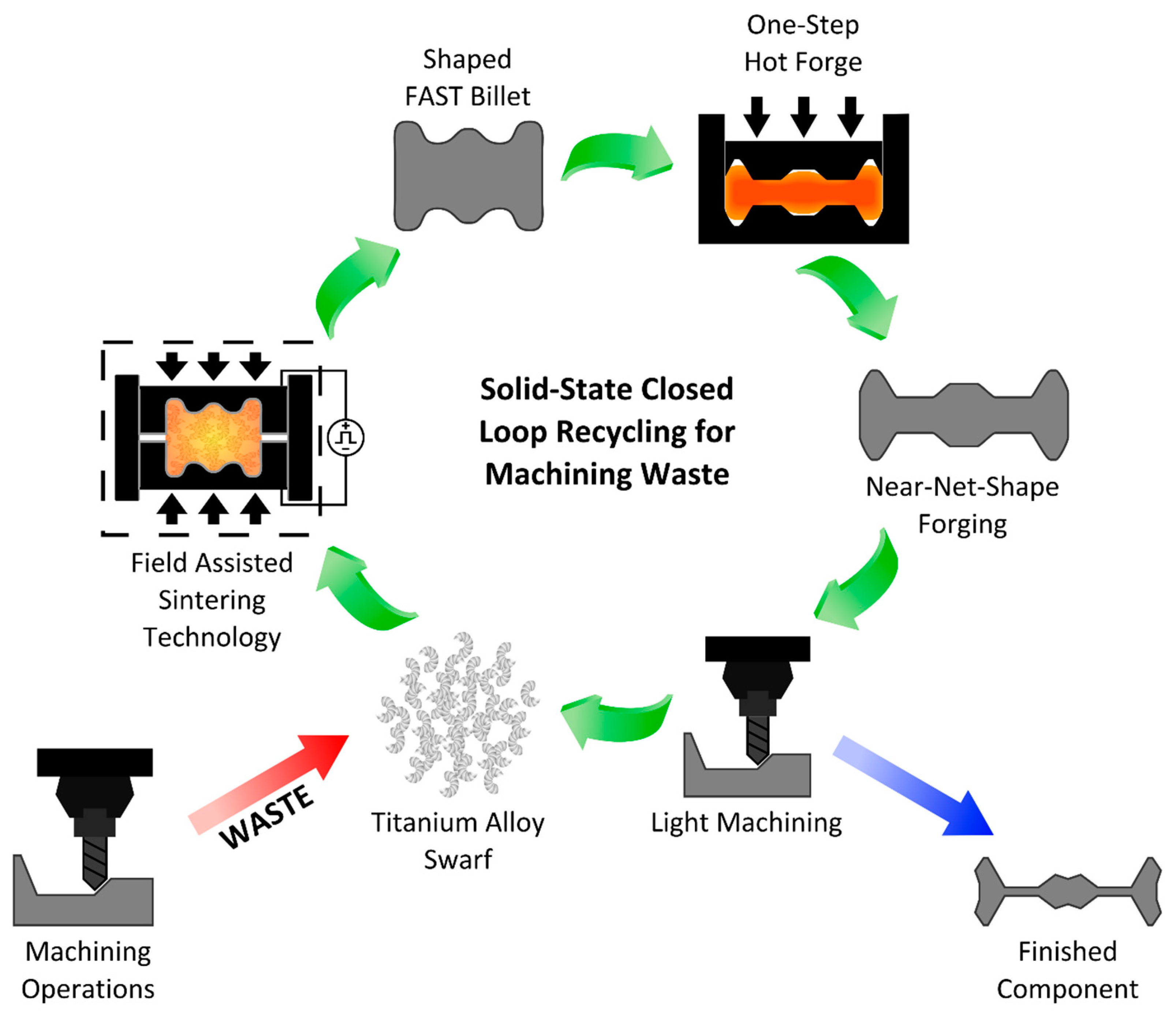
This paper describes a new method for consolidating aerospace waste of loose Ti-6Al-4V swarf into forged product in two simple solid-state processing steps—the University of Sheffield developed FAST-forge process [6]. In doing so, the study provides the basis of a disruptive closed-loop recycling approach for sustainable production of low-cost titanium alloy products in multiple sectors, as depicted in Figure 1.

Figure 1.
Schematic representing the solid-state closed-loop recycling approach, incorporating the FAST-forge process (where FAST stands for field assisted sintering technology), for sustainable production of low-cost titanium alloy components for multiple sectors.
2. Materials and Methods
2.1. Materials
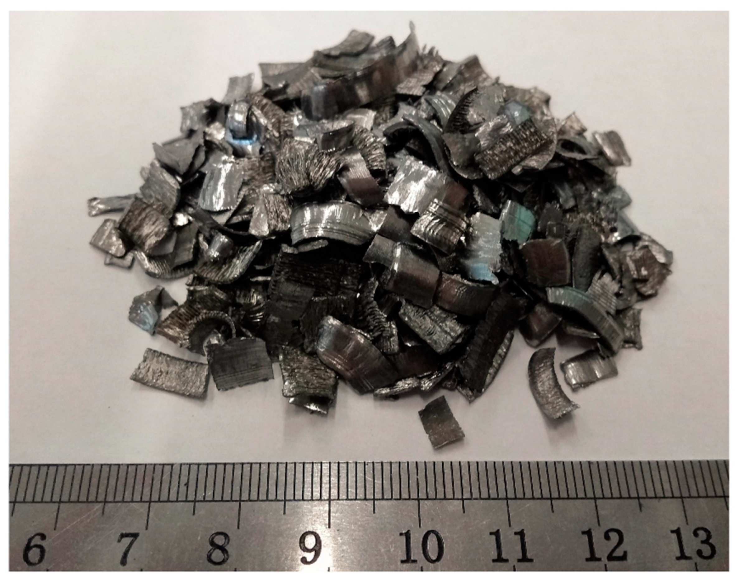
Grade 5 Ti-6Al-4V titanium alloy scrap in the form of machining swarf was procured for this study from Transition International Ltd (Sheffield, UK); see Figure 2. The swarf was conditioned via a grading and cleaning operation by Transition International to remove the contaminants present after machining; the details of this proprietary operation are commercially sensitive. The swarf was produced during machining of commercial high-quality titanium mill products and forgings for the aerospace sector. As such, it is expected to be within the ASTM International specification on composition for Grade 5 titanium and a full chemical analysis was not performed. However, the interstitial element content was measured due to the potential for significant contamination and oxidation during machining. An average of three repeat measurements is reported here. The inert gas fusion technique with an ELTRA ON 900 (Eltra GmbH, Haan, Germany) measured oxygen content to be 0.21% and nitrogen content to be 0.002%, and combustion analysis with an ELTRA CS 800 (Eltra GmbH, Haan, Germany) measured the carbon content at 0.03%. Thus, the Ti-6Al-4V swarf is within specification for these elements against the 0.08% carbon, 0.30% oxygen, and 0.05% nitrogen in ASTM B988-13 “Standard Specification for Powder Metallurgy (PM) Titanium and Titanium Alloy Structural Components”. However, the swarf is out of specification against the 0.08% carbon, 0.20% oxygen, and 0.05% nitrogen stated in ASTM B381-13 “Standard Specification for Titanium and Titanium Alloy Forgings” due to exceeding the oxygen level requirement by 0.01%. Importantly, the quantity of interstitial elements measured in the swarf will allow the material to remain within specification for ASTM B988-13 after FAST processing, where additional interstitial pick up of approximately 0.015% has been measured [7].

Figure 2.
Photograph of the Ti-6Al-4V machining swarf feedstock (also referred to as scrap, turnings, or chips) procured for this study. The swarf has gone through a commercial grading and cleaning operation to remove contamination after the machining process.
Additional hot forging data from previous unpublished work by the authors is also presented in Section 3.3 of this paper. This data from a conventional powder feedstock is intended to allow comparison of the forging behaviour of the Ti-6Al-4V swarf feedstock after FAST. The powder was Grade 5 Ti-6Al-4V 45–150 µm hydride–dehydride (HDH) (Phelly Materials (USA) Inc., Upper Saddle River, NJ, USA). The powder was certified to contain 6.22% Al, 4.00% V, 0.03% Fe, 0.01% C, 0.0135% H, 0.01% N, and 0.20% O, which meets specification for ASTM B988-13 and ASTM B381-13.
Ti-6Al-4V was selected for this study as it is the most used titanium alloy. It is designated as an α + β alloy, which means that, at room temperature, it typically contains both the α phase with a hexagonal close-packed crystal structure (harder to deform) and the β phase with a body cantered cubic crystal structure (easier to deform). As temperature is increased the volume fraction of β phase present increases. The temperature at which there is solely β phase present is known as the β transus temperature; for Ti-6Al-4V, this is typically approximately 990 °C. The mechanical properties and performance of Ti-6Al-4V can be modified by altering the room temperature volume fractions and morphologies of the two phases through thermomechanical processing above or below this transus temperature and selecting an appropriate cooling rate.
2.2. Methods
2.2.1. Field Assisted Sintering Technology (FAST)
The following information is summarized in Table 1. The swarf was consolidated using field assisted sintering technology (FAST) in a FAST Furnace Type HP D 25 (FCT Systeme GmbH, Rauenstein, Germany); further details of the equipment can be found in [6]. The HP D 25 system was used to create both 20.0 mm diameter by 4.3 mm thick discs from 6.0 g of Ti-6Al-4V swarf for a parametric study of FAST processing cycle conditions, and a 60.0 mm diameter by 10.3 mm thick disc from 130.0 g of Ti-6Al-4V swarf to extract hot compression test specimens.

Table 1.
Specimen information for the field assisted sintering technology (FAST) processing cycles performed.
The additional Ti-6Al-4V HDH hot forging data presented in Section 3.3 was obtained from specimens extracted from a 100.0 mm diameter by 22.0 mm thick disc made from 765.0 g of powder by a FAST Furnace Type H-HP D 250 (FCT Systeme GmbH, Rauenstein, Germany), based at Kennametal Manufacturing (UK) Ltd., Newport, Wales.
The same graphite die layup procedure was used for all specimens with both machines. A graphite ring die was lined with a layer of graphite foil. A cylindrical graphite punch was partially inserted into the bottom of the ring. Three graphite foil discs of the same diameter as the punch were inserted into the ring above the punch. The required mass of powder/swarf was then poured into the ring die and three further graphite foil discs placed above it. A second cylindrical graphite punch was inserted into the top of the ring die to complete the die assembly. The Type H-HP D 250 die assembly had two additional 15 mm thick discs of graphite placed between the foil and the punches to act as wear pads, which prevent damage to the punches. A graphite felt jacket was placed around the ring to prevent excessive radiative heat loss. The use of graphite foil between the metal and the graphite die aids with specimen removal and prolongs die life by preventing bonding between the components. The die assembly was placed between the two conducting hydraulic rams in the furnace’s vacuum chamber and an initial load was applied to ensure sufficient electrical contact was made. Conical graphite supports are used to adapt the diameter of the rams down to the diameter of the graphite punches.
The following sintering cycle was used, with the major points summarised in Table 2. The vacuum chamber was closed and evacuated. A pulsed 15 ms on and 5 ms off DC current was applied to produce Joule heating in the die assembly. The heating was initially uncontrolled up to 450 °C due to the limitations of the optical pyrometer used to measure and control the temperature. Above 450 °C, a constant heating rate was maintained up to the set dwell temperature; the load is simultaneously increased at a constant rate from the initial contact level up to the maximum dwell value by 900 °C. The dwell temperature and dwell load were then maintained for a specified dwell period. The current and power required at initial switch on and an average during the dwell period are also indicated in Table 2 for each specimen. The current and power linearly increase from initial values up to a maximum that was maintained during the dwell period. At the end of the dwell period the current was switched off and the die assembly allowed to cool, whilst the load was gradually decreased back to 5 kN. The average cooling rate for each specimen from the dwell temperature down to 600 °C is also show in Table 2.
Table 2.
FAST cycle parameters for the processed Ti-6Al-4V specimens.
2.2.2. One-Step Forging
Cylindrical Ti-6Al-4V swarf test specimens of 9 mm diameter by 13.5 mm height were removed from a 60 mm diameter by 10.3 mm thick FAST billet, as shown in Figure 3, to investigate their forgeability via axisymmetric hot compression testing. The University of Sheffield’s thermomechanical compression (TMC) machine was utilised to perform this testing; further information on the equipment can be found in [6]. The TMC consists of a load frame supporting two M22 steel tool posts with the upper one being servo-hydraulically actuated to allow constant strain rate deformations of specimens to a defined strain level. The tool posts can be placed within a programmable furnace to allow deformations to occur from room temperature up to 1050 °C. In this study, specimens were deformed to a strain of 1.2 at strain rates of 0.01, 0.1, and 1 s−1, and temperatures of 850, 900, and 950 °C. An induction heating unit immediately in front of the test furnace allows rapid heating (~4 °C·s−1 for this study) of test specimens to the desired deformation temperature, which was held for 120 s to allow homogenisation, before transfer to the test furnace. Temperature control is achieved through an N-type thermocouple embedded centrally in a 1.1 mm hole in the test specimen; see Figure 3. Test specimens are held in a pair of actuated robot gripper arms to allow fully automatic deformations to be programmed; heating, then deformation, followed by rapid withdrawal from the test furnace and water quenching. A thin boron nitride coating was applied to the specimen prior to testing to reduce frictional effects and help prevent interstitial pick up. Data is logged on time, temperature, load, velocity, and displacement during the test, which, combined with measurements of the pre- and post-test specimen dimensions, allows calculation of the true stress vs. true strain flow curves [8,9]. The deformed specimens were also sectioned parallel to the compression axis to allow microscopic examination of the central plane.
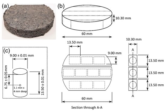
Figure 3.
(a) Photograph of the 60 mm diameter disc of Ti-6Al-4V swarf consolidated via FAST at 1200 °C and 20 MPa for 30 min; (b) Schematic showing the dimensions of the FAST disc, where it was sectioned, and the location and orientation the test specimens were extracted from; (c) Schematic showing the dimensions of the cylindrical axisymmetric hot compression test specimens.
2.2.3. Metallography
Standard titanium alloy metallographic preparation was followed for all specimens that were microscopically examined. The FAST and TMC specimens were abrasively sectioned to reveal the area of interest and hot mounted in Bakelite. The swarf feedstock was cold mounted in a two-part epoxy resin. Mounted specimens were then ground using progressively finer SiC papers and finally chemically-mechanically polished using 0.05 μm colloidal silica with 10% volume of 30% concentration hydrogen peroxide added. Micrographs were obtained using a Nikon Eclipse LV150 light microscope under reflected light conditions, either in the bright field or cross-polarized light mode. The microstructure of Ti-6Al-4V becomes more prominent when viewed under cross-polarized light conditions. The reflected light diffracts by varying amounts depending upon the local crystallographic orientation of the α phase. This is observed as variations in contrast (from black to white) in the micrographs and allows the size and morphology of the α phase to be seen. There is very little β phase present at room temperature in Ti-6Al-4V, and it is not possible to differentiate the β phase in same manner with polarized light. It is possible to estimate where grains of the β phase were present when the material was above the transus temperature by the propensity for the α phase to form first on, and grow along, these prior β grain boundaries. All micrographs presented in this work, apart from the as-received swarf feedstock, are oriented so that the axis of applied load during FAST or TMC processing aligns with length of the page.
The metallographically prepared specimens were also used to assess density by image analysis of bright field light micrographs, using the software ImageJ [10]. Micrographs were converted to 8-bit grayscale images and a threshold algorithm used to create black and white images so the porosity could be calculated from the percentage of black pixels present. Ten micrographs were analysed from random locations across each specimen to give an average density
3. Results and Discussions
3.1. As-Received Swarf Microstructure
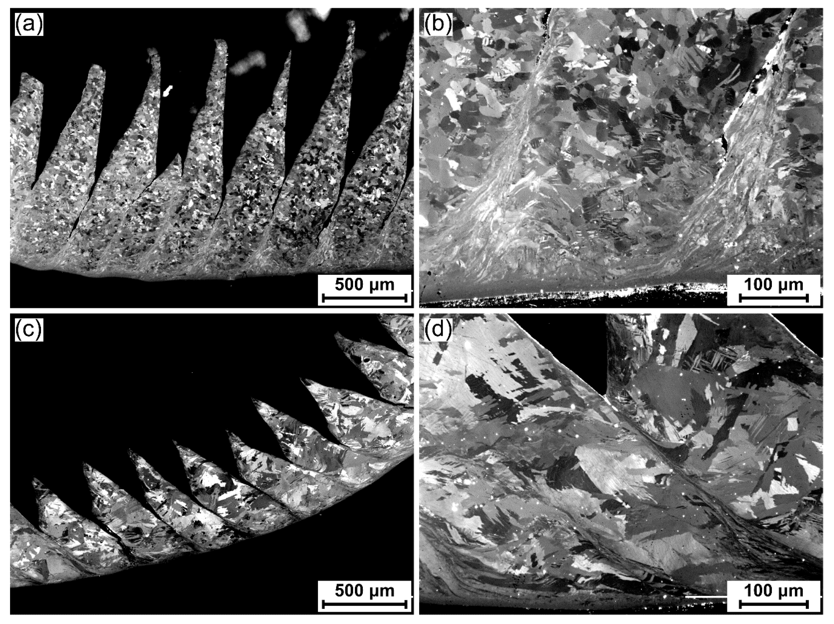
The microstructure of the as-received swarf can be seen in Figure 4. Two distinct varieties of swarf can be identified in the feedstock. The first variety displays a mill-annealed microstructure with equiaxed α grains [11]; see Figure 4a,b. The second variety displays a β-annealed microstructure with the α phase in a colony structure within transformed prior β grains [11]; see Figure 4c,d. This observation demonstrates one of the obstacles in dealing with what is essentially a waste product as a feedstock. The swarf was thought to be from a single source and of a single variety, but there has clearly been mixing of swarf from different machining operations. This could cause significant issues with achieving a homogeneous and high-quality product when recycling swarf through a solid-state processing route.
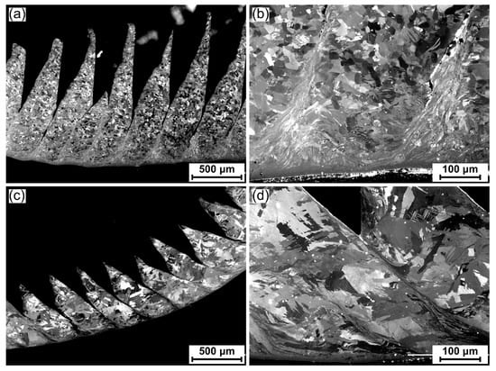
Figure 4.
Cross-polarized light micrographs of the Ti-6Al-4V swarf feedstock. Two distinct microstructural varieties of swarf were identified: one in a mill-annealed condition with equiaxed α grains (a) low magnification; (b) high magnification; and one in a β annealed condition with transformed β grains containing an α colony structure (c) low magnification; (d) high magnification.
The serrations, caused by adiabatic shear band formation as a result of severe plastic deformation during the machining process, can be seen in both varieties of swarf in Figure 4a,c. Figure 4b,d show these shear bands at increased magnification. The microstructure is severely deformed in these localized regions, with the bulk grain structure no longer discernible.
3.2. FAST Parametric Study
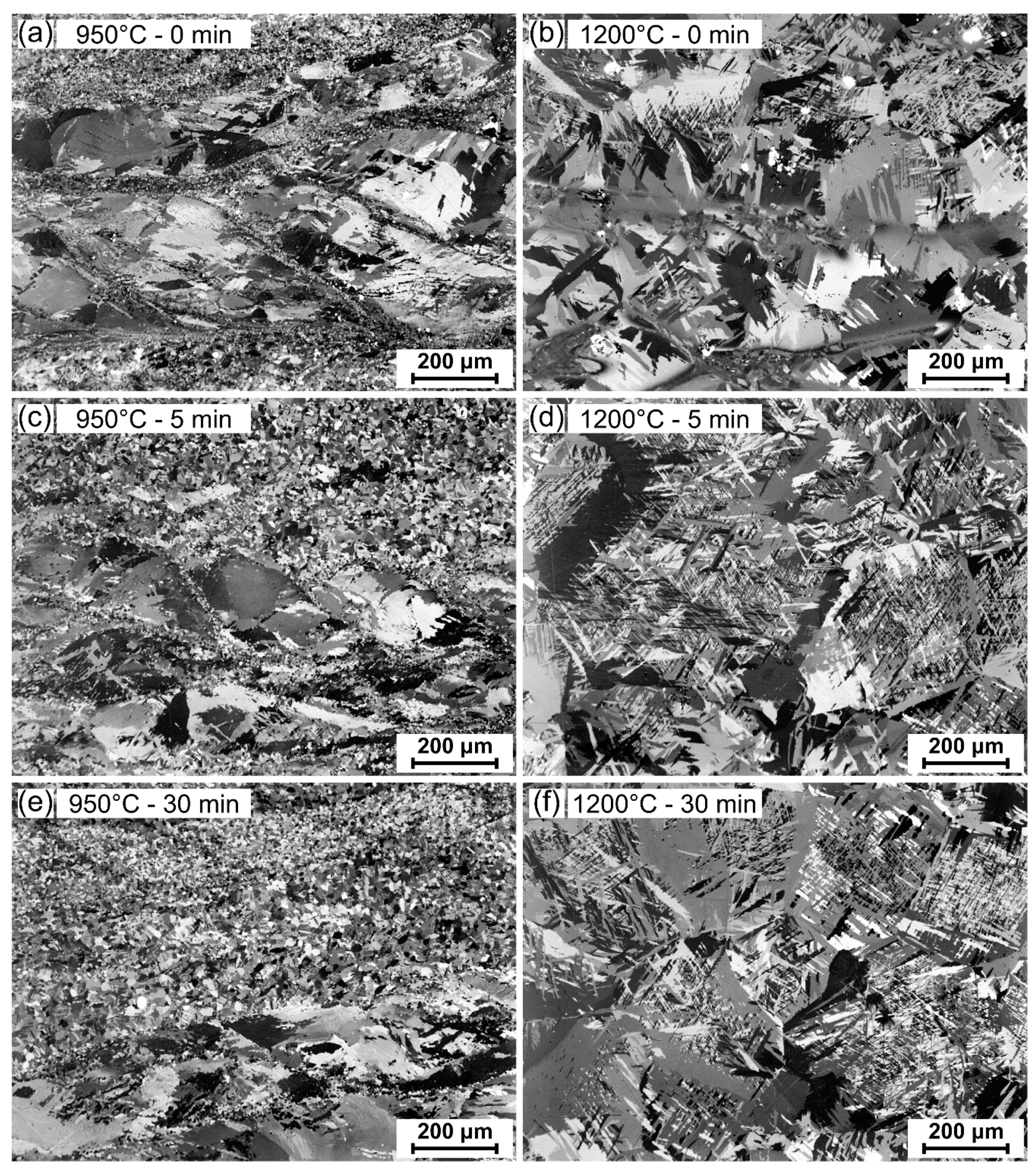
This section presents the microstructures, as shown in Figure 5, and densities, as shown in Table 3, of the Ti-6Al-4V swarf specimens after FAST processing at 950 or 1200 °C dwell temperature, for dwell times of 0 min, 5 min, or 30 min; referred to from this point as 950-0, 950-5, 950-30, 1200-0, 1200-5, and 1200-30, as indicated in the first six rows of Table 2.
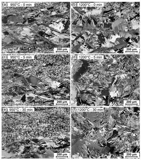
Figure 5.
Cross-polarized light micrographs showing the microstructural evolution of the Ti-6Al-4V swarf specimens with increasing FAST dwell temperature and/or dwell time, when using a fixed dwell pressure and heating rate: (a) 950 °C for 0 min; (b) 1200 °C for 0 min; (c) 950 °C for 5 min; (d) 1200 °C for 5 min; (e) 950 °C for 30 min; (f) 1200 °C for 30 min.
Table 3.
Density of swarf specimens after FAST processing at the indicated conditions.
The density for each specimen after FAST processing is reported in Table 3. The density increased with dwell time and dwell temperature as would be expected from classical sintering theory. The 1200 °C specimens achieved higher densities than the 950 °C specimens at each dwell time, and density increased for both temperatures as dwell time increased to 5 min then 30 min. The 950-0 and 1200-0 specimens had the lowest densities with 2.3% and 2.0% porosity respectively. Triangular voids are still visible where the serrations in the swarf feedstock have not been fully closed. The remaining four specimens all achieved greater than 99.0% density. The highest densities were achieved by processing at 1200 °C, with 99.8% measured after a 5 min dwell period and a slight improvement to 99.9% after a 30 min dwell period. The increased dwell temperature aided densification by enhancing the diffusional processes that are key to sintering and reducing the stress required to plastically deform the swarf particles. At 1200 °C, the material was significantly above the Ti-6Al-4V β-transus temperature and would have undergone the α to β phase transformation to give 100% β phase and a large increase in diffusivity. The self-diffusion of titanium in the β phase is increased by three orders of magnitude over the α phase [12]. The increased dwell times also allowed the diffusional sintering processes to progress and gradually remove the porosity. These density values are comparable to those reported for hot isostatic pressed Ti-6Al-4V powder [13,14] and are also in agreement with previous work reporting FAST processing of titanium powders at similar conditions [6,7], which indicates that sufficient mechanical properties can be achieved in the densified swarf material.
The microstructures of the Ti-6Al-4V swarf specimens after FAST processing at varying dwell temperatures and times can be seen in Figure 5. There is a clear lack of homogenization in the specimens processed at 950 °C, below the β transus temperature (~990 °C), at all dwell times; see Figure 5a,c,e. There are distinct banded regions of dissimilar microstructures running perpendicular to the applied FAST load direction. In general, these regions display either approximately equiaxed α grains or transformed β grains with a colony α structure, which strongly correlate with the mill- and beta-annealed microstructures observed in the as-received swarf feedstock; see Figure 4. The 950-0 specimen, as shown in Figure 5a, has the finest α grains in the mill-annealed swarf areas and the most distinct areas of beta-annealed swarf. The adiabatic shear bands present in the swarf feedstock are still visible in both microstructures, although more prominent in the beta-annealed areas, and they are now decorated with very fine-scale α grains; the large quantities of stored energy in these severely deformed areas promote recrystallisation processes after even short times at the FAST dwell temperature. As the dwell time increases to 5 min, as shown in Figure 5c, and 30 min, as shown in Figure 5e, there is a slight homogenization of the microstructure. There is grain growth in the mill-annealed swarf areas and the original shear bands are consumed by fine recrystallized regions. The recrystallized α grains formed in the beta-annealed shear bands begin to grow and separate the transformed β grains into distinct pockets containing α grain colonies surrounded by finer equiaxed α grains.
There is a clear change in the Ti-6Al-4V swarf specimens after FAST processing above the β-transus temperature at 1200 °C; see Figure 5b,d,f. The distinct banded regions of dissimilar microstructures that correlate to the swarf feedstock, which were visible in the 950 °C specimens, are no longer recognizable. There is a homogeneous transformed β microstructure with fine α laths in Widmanstätten (basketweave) pattern and a small quantity of α phase on the prior β grain boundaries. The prior β grains are approximately 200–500 µm in diameter. The small amount of porosity present in the 1200-0 specimen, visible in the lower left quadrant of Figure 5b, has prevented complete homogenization of the microstructure due to the voids restricting grain boundary motion and grain growth in those areas. However, in the 1200-5 and 1200-30 specimens it is no longer possible to discern that the material was derived from a swarf feedstock, as solid-state diffusion and the dynamic restoration processes led to a complete transformation from the as-received swarf microstructure and almost full consolidation. The size and uniform nature of the prior β grains in the microstructure indicate that the increased diffusional processes occurring at the higher FAST temperature have allowed complete diffusion bonding of the swarf particles to occur; the grains have grown beyond the prior swarf particle boundaries. These microstructures correspond well with those seen when processing commercial high-cost titanium alloy powders under similar FAST conditions [6].
From these results, it appears unlikely that a complete homogenization of the microstructure would be possible when FAST processing below the β-transus temperature (in a realistic dwell time) when consolidating a mixed microstructure swarf feedstock. However, if a swarf feedstock with a uniform microstructure could be sourced, then sub-transus processing would be possible, and perhaps beneficial. Significantly, it was possible to fully densify and homogenize the microstructure of the mixed microstructure swarf feedstock when FAST processing above the β-transus temperature, even at relatively short dwell times. This tolerance of swarf microstructure offers benefits when securing a plentiful and low-cost feedstock for the FAST-forge process.
3.3. Hot Forging Study
The parametric study indicated that FAST processing parameters of a heating rate of 100 °C·min−1 to a dwell temperature of 1200 °C, with 45 MPa applied pressure, held for 5 min would be sufficient to produce a highly dense and microstructurally homogeneous specimen for a subsequent hot forging study. These conditions were used as a benchmark when selecting the FAST processing cycle to produce the 60 mm diameter disc from which to extract the cylindrical TMC specimens. The applied pressure was reduced to 20 MPa due to limitations in the strength of the 60 mm diameter graphite ring die. The heating rate was also reduced to 50 °C·min−1 to match what was achieved when producing the 100 mm diameter disc on the large-scale Type H-HP D 250 furnace. A dwell time of 30 min was selected to negate the effect of the reduced pressure. Prior work has shown that the dwell pressure has little effect on the microstructure as long as it is high enough to achieve almost full consolidation, and the effect of heating rate is also minimal within the range used in this study [7].
3.3.1. As-FAST Microstructures
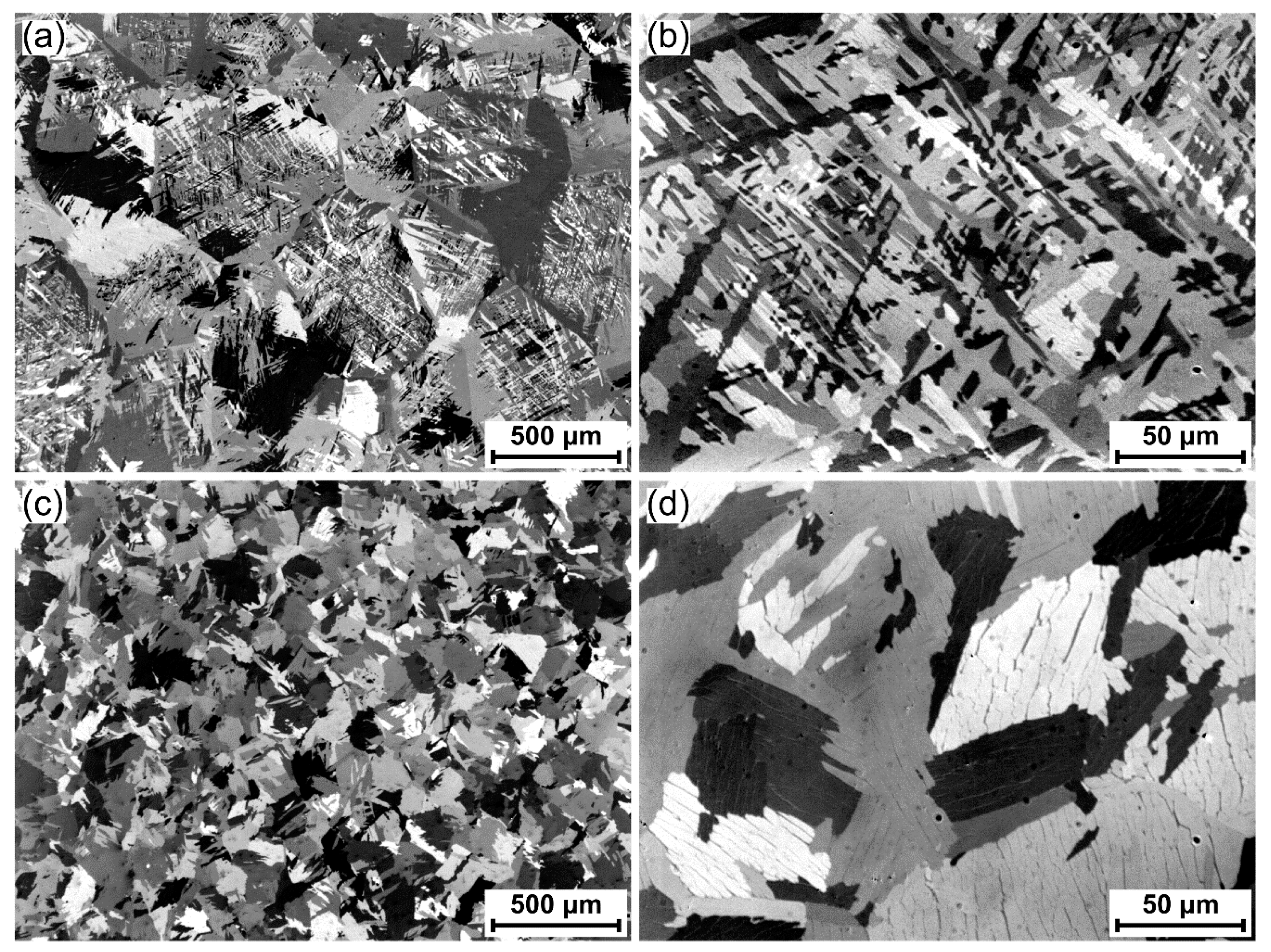
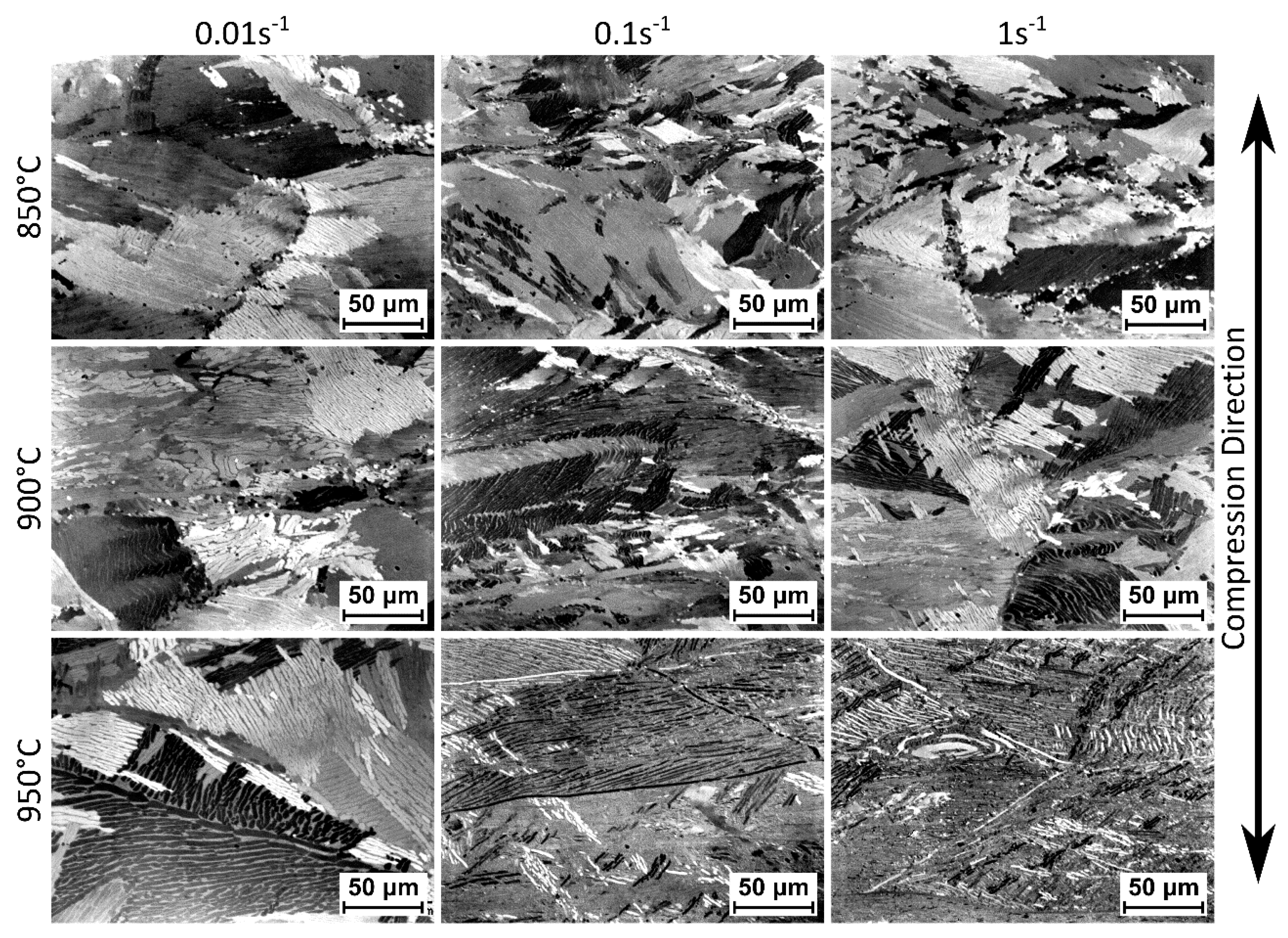
The as-FAST microstructure of the 60 mm diameter disc consolidated from Ti-6Al-4V swarf and the 100 mm diameter disc consolidated from Ti-6Al-4V HDH powder are shown in Figure 6. Microstructural homogeneity has been shown across a 250 mm diameter disc in previous work, so the microstructures shown here are presumed to be representative of the whole specimen [7]. The 60 mm swarf specimen microstructure is almost identical to those produced at 1200 °C with 5 and 30 min dwells in the parametric study; see Figure 5d,f. There is again a homogeneous transformed β microstructure with prior β grains that are approximately 500 µm in diameter and a small quantity of α phase on the prior β grain boundaries; see Figure 6a. The prior β grains contain Widmanstätten α laths with 1–3 µm width; see Figure 6b. The density of the 60 mm specimen is 99.9%. The microstructural similarity and equivalent density confirm the reduced applied pressure and heating rate had the suspected minimal effect.

Figure 6.
Cross-polarized light micrographs showing the microstructure of a 60 mm diameter disc of Ti-6Al-4V swarf after FAST processing at 1200 °C for 30 min: (a) low magnification; (b) high magnification. For comparison, cross-polarized light micrographs showing the microstructure of a 100 mm diameter disc of Ti-6Al-4V HDH powder after FAST processing at 1200 °C for 30 min: (c) low magnification; (d) high magnification.
The microstructure of the 100 mm diameter Ti-6Al-4V HDH specimen is different to the swarf specimen of a smaller diameter. The HDH microstructure is again a homogeneous transformed β structure but lacks the obvious prior β grain boundaries visible in the swarf specimen; see Figure 6c. The α phase laths are also thicker at 5–10 µm and arranged in 25–100 µm wide colonies rather than the Widmanstätten morphological structure present in the swarf specimen; see Figure 6d.
The significant microstructural difference between the two specimens is most likely explained by the different cooling rates they experienced [12]. The 60 mm specimen had an average cooling rate from 1200 to 600 °C of 280 °C·min−1, whilst the 100 mm specimen had an average cooling rate from 1200 to 600 °C of 20 °C·min−1. These were the natural cooling rates achieved by the two different FAST furnaces when the current is removed, and the heat is dissipated via the water-cooled hydraulic rams. The significantly slower cooling rate in the larger specimen is due to the much larger graphite die assembly required, which leads to a larger thermal mass to cool.
3.3.2. As-Forged Microstructures
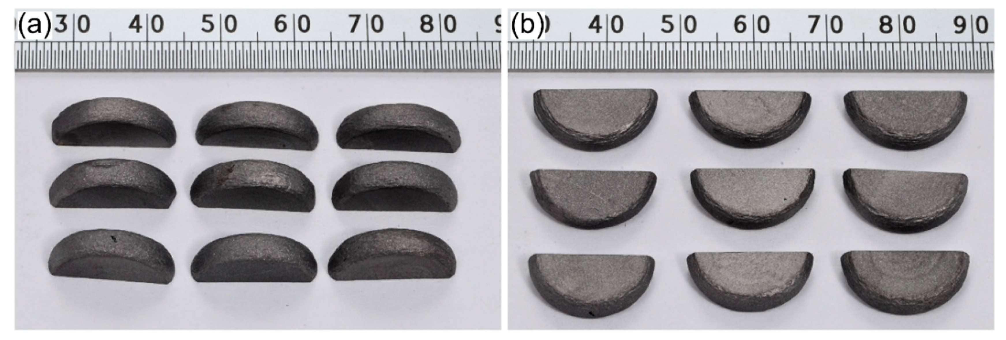
The Ti-6Al-4V swarf FAST specimens after hot compression can be seen in Figure 7, where they have been abrasively sectioned in half parallel to the compression direction to allow metallographic preparation. The deformed specimens show no visual signs of edge cracking or defects during hot compression at all temperatures and strain rates, up to a bulk average strain of 1.2. Importantly, this demonstrates that FAST swarf billets have good forgeability.
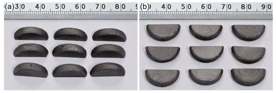
Figure 7.
Photographs of (a) side view and (b) top view of the Ti-6Al-4V swarf specimens consolidated via FAST at 1200 °C for 30 min after a subsequent hot compression at 950 °C (top row), 900 °C (middle row), and 850 °C (bottom row), and a strain rate of 0.01 s−1 (left column), 0.1 s−1 (middle column), and 1 s−1 (right column). The deformed specimens have been abrasively sectioned in half to allow metallographic preparation.
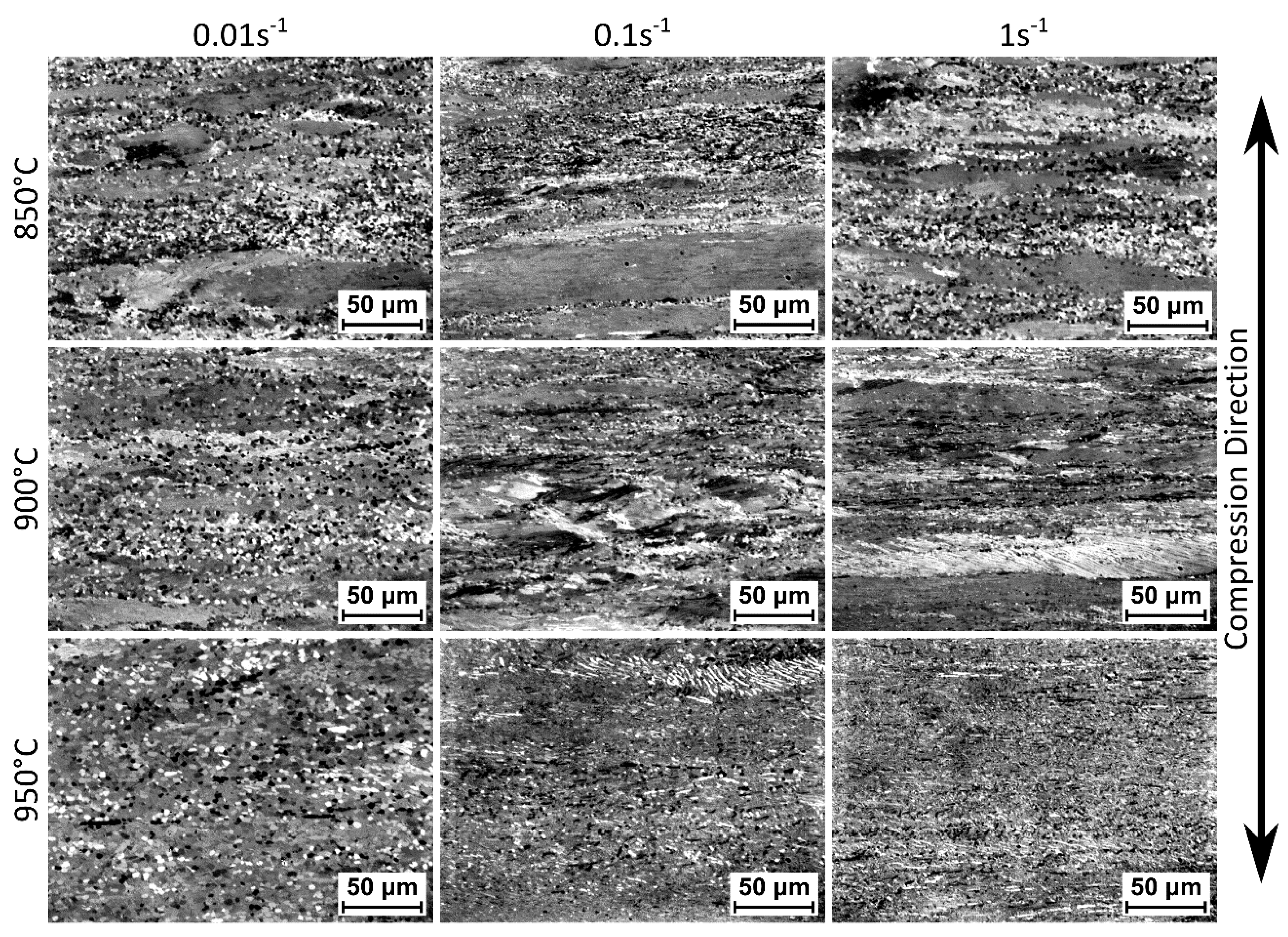
Cross-polarized light micrographs showing the microstructure of the Ti-6Al-4V swarf FAST specimens after hot compression in the central high-strain region and the low strain dead zone (centre of upper surface) can be seen in Figure 8 and Figure 9, respectively. The specimens remain at least 99.9% dense, with no porosity generated during hot compression. In the high-strain regions, as shown in Figure 8, there has been pancaking of the prior β grains, and a rotation of the primary α laths, perpendicular to the compression direction. There has also been significant dynamic recrystallisation and globularisation of the α laths, which can be seen in the areas with approximately equiaxed α grains. The volume fraction of dynamic recrystallisation and globularisation increases with increasing temperature and decreasing strain rate, which is likely due to an order of magnitude more time for any diffusional processes to occur. In the low strain regions, as shown in Figure 9, the hot compression has had less effect on the microstructure. The prior β grains have elongated slightly perpendicular to the compression direction. A colony α structure has developed compared to the basketweave structure seen after FAST, and there has been a slight coarsening of the α laths. The 850 °C and 900 °C specimens have visible bending and kinking of the α laths, frequently extending across entire colonies, which is less prominent in the 950 °C specimens.
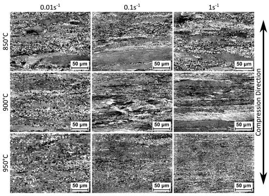
Figure 8.
Cross-polarized light micrographs of higher-strain central regions in Ti-6Al-4V swarf specimens consolidated via FAST at 1200 °C for 30 min after a subsequent hot compression at 850, 900, or 950 °C, and a strain rate of 0.01, or 0.1, or 1 s−1 (as labelled).

Figure 9.
Cross-polarized light micrographs of lower strain dead zone regions in Ti-6Al-4V swarf specimens consolidated via FAST at 1200 °C for 30 min after a subsequent hot compression at 850, 900, or 950 °C, and a strain rate of 0.01, or 0.1, or 1 s−1 (as labelled).
Significantly, the microstructural evolution and micrographs presented in Figure 8 and Figure 9 are indistinguishable from those that would be found when performing hot compressions of conventional melt-wrought Kroll process derived titanium alloy material [15,16,17]. The FAST-forge process offers high levels of control and the ability to utilize conventional titanium hot forging knowledge and practices.
3.3.3. Hot Deformation Flow Curves
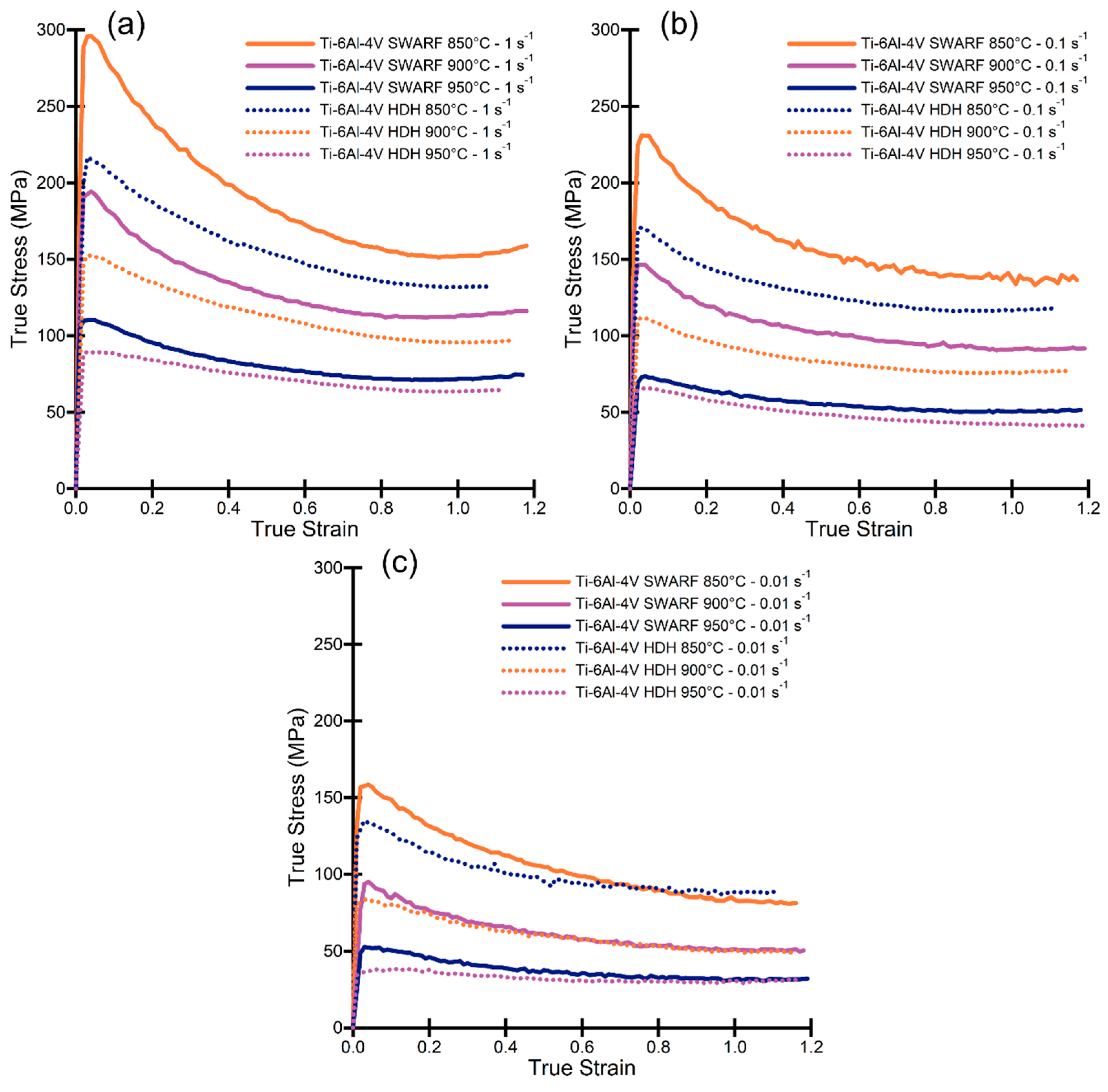
Flow curves of the true stress vs. true strain behaviour for the Ti-6Al-4V swarf specimens, consolidated via FAST, under axisymmetric hot compression at temperatures of 850, 900, and 950 °C, and strain rates of 0.01, 0.1, and 1 s−1 are shown in Figure 10. Equivalent flow curves for Ti-6Al-4V HDH powder consolidated via FAST before hot compression are also shown in Figure 10 for comparison.
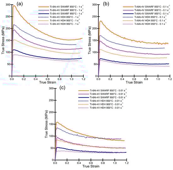
Figure 10.
Flow curves showing true stress vs. true strain behaviour for Ti-6Al-4V swarf consolidated via FAST under axisymmetric compression at 850, 900, and 950 °C: (a) deformed with a strain rate of 1 s−1; (b) deformed with a strain rate of 0.1 s−1; (c) deformed with a strain rate of 0.01 s−1. Flow curves for Ti-6Al-4V HDH powder consolidated via FAST are also shown for comparison.
As expected, the flow stress decreases with decreasing strain rate and with increasing temperature due to an increased volume fraction of the more easily deformed β phase and a greater time for dynamic recovery and recrystallisation processes to occur. All the curves exhibit a transient period of rapid hardening up to a maximum peak stress at a strain of <0.05, followed by a period of continuous flow softening to a strain of between 0.8 and 1.0. The flow softening behaviour has been attributed to the rotation of α lamellae to ‘softer’ orientations and the evolution of dislocation substructure within the lamellae [15,16,17]. Globularisation of the α phase, as seen in Figure 7, then begins through fragmentation of the α lamellae by a boundary splitting mechanism, where the boundaries in the lamellae are created through continuous dynamic recrystallization processes, and particle spheroidization progresses by means of termination migration [15]. A steady-state flow stress occurs after a strain of ~0.8–1.0 when the mechanisms causing flow softening are balanced by the work hardening processes occurring.
The flow curves for Ti-6Al-4V HDH specimens consolidated via FAST exhibit a decreased maximum peak stress at every test condition compared to the Ti-6Al-4V swarf specimens; there is also a decrease in the steady-state flow stress, but it is less pronounced. The difference in flow behaviour between the two materials is largest at the lowest temperatures and highest strain rates, with the HDH curves at 900 °C/0.01 s−1 and 950 °C/0.01 s−1 being very similar to the equivalent swarf curves. The interstitial content for the two materials is similar and would therefore not be expected to produce the differences seen in Figure 10. However, there was a difference in the microstructure of the two materials after FAST processing, with an α lath thickness of ~1–3 µm in the swarf and ~5–10 µm in the HDH powder; see Figure 6. The α lath thickness has been shown to have a Hall–Petch-type effect on the peak flow stress, with finer α laths producing higher peak stresses [18]. The microstructures of the two materials used in this study and the values (and differences) of the flow curves are very similar to results published by Semiatin and Bieler on the effect of α lath thickness on plastic flow during hot working of Ti-6Al-4V [18].
3.3.4. Microstructural Evolution Comparison of Swarf with HDH Powder Post FAST-forge
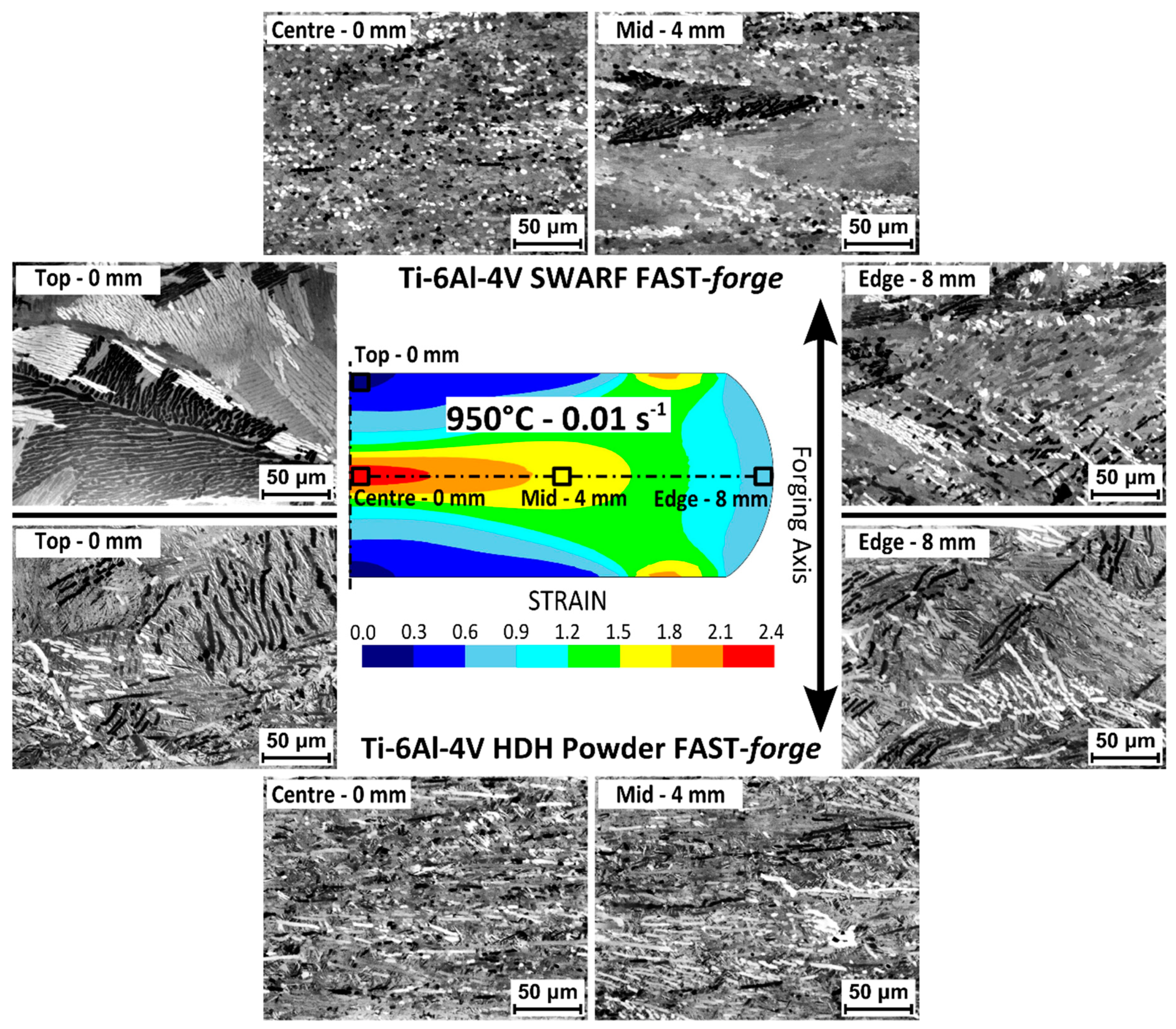
The evolution of the microstructure in the Ti-6Al-4V swarf and Ti-6Al-4V HDH specimens with increasing strain after hot compression at 950 °C at a strain rate of 0.01 s−1 is shown in Figure 11. Cross-polarized light micrographs were taken from four locations on the cross-section of the deformed specimen as indicated; three were spaced equally, 4 mm apart, along the specimen centre line, and a fourth was located centrally in the upper surface.

Figure 11.
Cross-polarized light micrographs of the microstructural evolution with increasing strain from the top/edge to the centre of a specimen after hot compression at 950 °C and 0.01 s−1; test specimens were produced from Ti-6Al-4V swarf consolidated via FAST (top) and Ti-6Al-4V HDH powder consolidated via FAST (bottom).
In the lower strain regions, there are minimal changes from the as-FAST microstructure, with some coarsening of the α laths noticeable in the swarf specimen. Moving from lower strain regions to higher-strain regions, for both the swarf and HDH specimen, it can be seen there is a rotation of the primary α platelets to align perpendicular to the compression direction. At the mid-point of the specimen (a strain of ~1.5–1.8) the rotation appears to be fully complete and the globularisation process has initiated. At the centre of the specimen (a strain of ~2.1–2.4) there has been significant fragmentation of the α laths due to the globularisation process. These values of strain for the onset and completion of globularisation largely agree with those previously reported for the hot deformation of Ti-6Al-4V with a transformed β microstructure [19].
The α grains in the swarf specimen have become mostly equiaxed, which indicates the globularisation process has completed. There are some equiaxed α grains in the HDH specimen but there are also still α grains with a high aspect ratio, which implies dynamic globularisation. The effect of starting microstructure on the level of strain required to fully globularise Ti-6Al-4V with a transformed β microstructure has also been reported previously, with thicker α laths retarding the globularisation process [17], which is in agreement with the observations in this study of the finer post-FAST swarf microstructure containing more equiaxed α grains after hot compression than the coarser post-FAST HDH microstructure.
4. Conclusions
This study has demonstrated the possibility of using the hybrid FAST-forge process as an effective route to recycle titanium alloy swarf: a fully dense, and microstructurally refined, forged titanium alloy specimen was created from Ti-6Al-4V swarf in two solid-state processing steps. In doing so, the study provides the basis of a disruptive closed-loop recycling approach for sustainable production of low-cost titanium alloy products. Reusing titanium alloy swarf as a raw material for producing new components with as-forged microstructures and mechanical properties reduces the environmental impact of scrapping a material with inherently high associated energy costs from primary extraction and multi-stage processing routes. Additionally, the FAST-forge process provides better mechanical properties than additive manufacturing routes and a faster manufacturing route than either additive manufacturing or hot isostatic pressing (HIP). Titanium alloy swarf as a low-cost feedstock for the FAST-forge process is game-changing for the economics of titanium alloy components.
Author Contributions
Conceptualization, N.S.W. and M.J.; methodology, N.S.W. and M.J.; supervision, M.J.; investigation, N.S.W.; formal analysis, N.S.W.; visualization, N.S.W.; writing—original draft preparation, N.S.W. and M.J.; writing—review and editing, N.S.W. and M.J. All authors have read and agreed to the published version of the manuscript.
Funding
This research received no external funding.
Acknowledgments
We wish to acknowledge the Henry Royce Institute for Advanced Materials, funded through EPSRC grants EP/R00661X/1, EP/S019367/1, EP/P02470X/1 and EP/P025285/1, for access to the FCT Systeme HP D 25 FAST/SPS furnace and Servotest Thermo-Mechanical Compression (TMC) equipment at Royce@Sheffield. We also acknowledge Transition International Ltd for supply of the titanium alloy swarf used in this work. Additional thanks go to Jonathan Wanless for assistance with the FAST processing, and Jacob Pope for proof reading services.
Conflicts of Interest
The authors declare no conflict of interest.
References
- Jackson, M.; Boyer, R.R. Titanium and its Alloys: Processing, Fabrication and Mechanical Performance. In Encyclopedia of Aerospace Engineering; Blockley, R., Shyy, W., Eds.; John Wiley & Sons, Ltd.: Chichester, UK, 2010. [Google Scholar]
- AIRBUS Global Market Forecast: Cities, Airports & Aircraft 2019-2038. Available online: https://www.airbus.com/aircraft/market/global-market-forecast.html (accessed on 13 January 2020).
- Froes, F.H. Titanium: Physical Metallurgy, Processing, and Applications, 1st ed.; ASM International: Materials Park, OH, USA, 2015. [Google Scholar]
- Zak Fang, Z.; Sun, P. Pathways to optimize performance/cost ratio of powder metallurgy titanium—A perspective. Key Eng. Mater. 2012, 520, 15–23. [Google Scholar] [CrossRef]
- Hoyle, C. Features—Critical Capabilities—Flight International. Available online: https://www.flightglobal.com/fixed-wing/bae-systems-studies-production-path-beyond-eurofighter-typhoon/134187.article (accessed on 17 January 2020).
- Weston, N.S.; Jackson, M. FAST-forge—A new cost-effective hybrid processing route for consolidating titanium powder into near net shape forged components. J. Mater. Process. Technol. 2017, 243, 335–346. [Google Scholar] [CrossRef]
- Weston, N.S.; Derguti, F.; Tudball, A.; Jackson, M. Spark plasma sintering of commercial and development titanium alloy powders. J. Mater. Sci. 2015, 50, 4860–4878. [Google Scholar] [CrossRef]
- Roebuck, B.; Lord, J.D.; Brooks, M.; Loveday, M.S.; Sellars, C.M.; Evans, R.W. Measurement Good Practice Guide No 3—Measuring Flow Dtress in Hot Axisymmetric Compression Tests; National Physical Laboratory: Teddington, UK, 2002. [Google Scholar]
- Weston, N.S. A Novel Solid-State Processing Route to Generate Cost-Effective Titanium Alloy Components. Ph.D. Thesis, The University of Sheffield, Sheffield, UK, 30 October 2017. [Google Scholar]
- Rasband, W.S. ImageJ. Available online: http://imagej.nih.gov/ij/ (accessed on 1 January 1997).
- Lampman, S. Wrought Titanium and Titanium Alloys. In ASM Handbook Volume 2—Properties and Selection: Nonferrous Alloys and Special-Purpose Materials; ASM Handbook Committee, Ed.; ASM International: Materials Park, OH, USA, 1990; ISBN 978-1-62708-162-7. [Google Scholar]
- Lutjering, G.; Williams, J.C. Titanium, 2nd ed.; Springer: New York, NY, USA, 2007; ISBN 978-3-540-71397-5. [Google Scholar]
- Kim, Y.; Kim, E.-P.; Song, Y.-B.; Lee, S.H.; Kwon, Y.-S. Microstructure and mechanical properties of hot isostatically pressed Ti–6Al–4V alloy. J. Alloys Compd. 2014, 603, 207–212. [Google Scholar] [CrossRef]
- Xu, L.; Guo, R.; Bai, C.; Lei, J.; Yang, R. Effect of hot isostatic pressing conditions and cooling rate on microstructure and properties of Ti-6Al-4V alloy from atomized powder. J. Mater. Sci. Technol. 2014, 30, 1289–1295. [Google Scholar] [CrossRef]
- Zherebtsov, S.; Murzinova, M.; Salishchev, G.; Semiatin, S.L. Spheroidization of the lamellar microstructure in Ti–6Al–4V alloy during warm deformation and annealing. Acta Mater. 2011, 59, 4138–4150. [Google Scholar] [CrossRef]
- Miller, R.M.; Bieler, T.R.; Semiatin, S.L. Flow softening during hot working of Ti-6Al-4V with a lamellar colony microstructure. Scr. Mater. 1999, 40, 1387–1393. [Google Scholar] [CrossRef]
- Shell, E.B.; Semiatin, S.L. Effect of initial microstructure on plastic flow and dynamic globularization during hot working of Ti-6Al-4V. Metall. Mater. Trans. A 1999, 30, 3219–3229. [Google Scholar] [CrossRef]
- Semiatin, S.L.L.; Bieler, T.R. The effect of alpha platelet thickness on plastic flow during hot working of Ti-6Al-4V with a transformed microstructure. Acta Mater. 2001, 49, 3565–3573. [Google Scholar] [CrossRef]
- Semiatin, S.L.; Seetharaman, V.; Weiss, I. Flow behavior and globularization kinetics during hot working of Ti–6Al–4V with a colony alpha microstructure. Mater. Sci. Eng. A 1999, 263, 257–271. [Google Scholar] [CrossRef]

© 2020 by the authors. Licensee MDPI, Basel, Switzerland. This article is an open access article distributed under the terms and conditions of the Creative Commons Attribution (CC BY) license (http://creativecommons.org/licenses/by/4.0/).