Article

Surface Quality and Free Energy Evaluation of s275 Steel by Shot Blasting, Abrasive Water Jet Texturing and Laser Surface Texturing

1
Faculty of Engineering, Mechanical Engineering and Industrial Design Department, University of Cadiz, Av. Universidad de Cadiz 10, Puerto Real, 11519 Cadiz, Spain
2
Nanotures SL, C. Inteligencia 19, Tecnoparque Agroalimentario, Jerez de la Frontera, 11591 Cadiz, Spain
*
Author to whom correspondence should be addressed.
Metals 2020, 10(2), 290; https://doi.org/10.3390/met10020290
Submission received: 22 January 2020 / Revised: 18 February 2020 / Accepted: 20 February 2020 / Published: 22 February 2020
(This article belongs to the Special Issue Surface Modification Technology in Metals)

Abstract

:
Surface modification by different technologies prior to joining operations or improving tribological properties is a point of great interest. Improving surface activation by increasing the roughness of the metal is a relationship that is becoming more defined. In turn, an increase in surface wettability by evaluating contact angles indicates surface activation by obtaining a high surface free energy. Technologies such as shot blasting and laser surface texturing (LST) have generated several scientific studies where they have identified the influence of parameters on the formation of rough surfaces with defined patterns. However, the application of abrasive water jet texturing (AWJT) has been little studied as an alternative. This article compares these technologies in the texturing of a carbon steel s275 in order to identify the relationship between surface quality and surface activation. It has been determined that AWJT produces the highest Rt values close to 64 µm with a cross feed of 0.45 mm and a traverse speed of 5000 mm/min. Furthermore, LST obtains the best values of free surface energy by combining a power of 20 W with a frequency of 20 kHz and a sweeping speed of 10 mm/s. Finally, contour diagrams have been obtained which relate these variables to the texturing parameters.

1. Introduction

The modification of metal alloy surfaces to improve their functional performance is a hot research topic nowadays. The surface characteristics of these alloys make it possible to differentiate between hydrophobic and hydrophilic surfaces [1]. The latter are of great interest in the field of material bonding.
In recent years, metal alloys have been used in the form of hybrid structures [2,3]. These structures are composed of dissimilar materials that complement their advantages by offering unique characteristics [4,5]. This has been of great interest for the aeronautical sector, where the combination of titanium or aluminum alloys with carbon fiber reinforced composites generates a structure with an excellent weight-to-mechanical property ratio [6,7,8,9]. However, the main method of joining these materials is mechanical, giving rise to a series of defects such as the concentration of stresses and the need for high-precision drilling prior to joining [10].
For this reason, it is necessary to apply another type of joint that avoids this defectology and ensures a correct joint. Thus, bonding technologies are generating interest, capable of generating a continuous bond between both materials and, at the same time, reduce the final weight of the structure by avoiding the use of mechanical joints such as rivets [10,11,12].
A hybrid structure of great interest in recent years for various industrial sectors is the combination of steel with a thermoplastic matrix composite material (CFRTP) [13], especially in the automotive sector. CFRTPs are characterized by a high degree of automation in their manufacturing process [14,15]. In addition, they have excellent impact resistance which, in combination with the excellent mechanical properties of steel, produce high quality final structures that reduce the final weight of the vehicle and its consumption [16,17].
Nevertheless, the bonding of these materials is a major challenge. There is not much literature on the importance of factors affecting the final joint. In addition, the final state of the steel surface can directly affect the quality of the final joint. One of the most critical phases in obtaining a good bond when using adhesives is the surface preparation of the substrates. Because of this, it is necessary to ensure a very good contact between the adhesive and the adherent by modifying the latter’s surface [18,19].
Surface modification technologies such as shot blasting and laser surface texturing have been well studied in order to activate the surface metal alloys for further operations. In these studies, a correlation is established between the surface quality obtained with surface activation in terms of surface free energy. However, there is no specific comparison between these technologies in order to introduce improvements in the surface preparation of metallic alloys.
In this way, the degree of adhesion on the surface of the steel is directly related to its final surface quality and the free surface energy that is generated. According to the literature [18], an increase in the roughness of the surface generated produces an increase in the peaks and valleys generated on the surface. This allows the adhesive to adhere completely to the surface, reaching a higher free surface energy value. For these reason, an increase in roughness produces an increase in the effective surface prior to joining [20]. A relationship between roughness and parameter variation in sand-blasting was established in [21]. Thus, the variation in roughness in steels is more dependent on the type of abrasive particle used than the variation in pressure applied. In addition, the increase in roughness through shot blasting makes it possible to obtain hydrophilic surfaces and increase the mechanical properties of the steel [22], increasing the final quality of the joint with dissimilar materials and improving the shear resistance [23].
Another area of interest in surface modification is the reduction of wear caused. Generating high-precision microgeometric cavities by means of different technologies such as laser texturing allows for better lubrication of these surfaces, improving their tribological properties [1,24,25,26].
On the other hand, an excess in this roughness can be negative. If the cavities generated are very high, the penetration capacity of the adhesive decreases, generating a worse bonding quality due to the formation of localized stress concentration [27]. To achieve this, different technologies have been studied nowadays, the most interesting being shot blasting and laser surface texturing. To determine the type of surface generated, wettability tests have been performed and by means of the Owens–Wendt–Rabel–Kabele (OWRK) equation the free surface energy can been determined [28].
Campos et al. [29] studied the application of different types of milk in steel samples to determine the degree of adhesion of Enterobacter sakazakii bacteria in these samples. For its evaluation, they studied its adhesion based on the contact angle obtained and the free surface energy that the steel presented when depositing these liquids. It is necessary to understand and be able to control the texture generated in solids in order to be able to modify their adhesion capacity according to the desired needs.
In this sense, the superficial modification of a carbon steel by laser surface texturing was able to reduce the contact angle on that surface, increasing the polar component and, therefore, the free surface energy [30]. In this way, Lawrence et al. corroborated that these type of techniques are capable of activating the surface of the substrate, increasing its free surface energy and its binding capacity. In this study, the results of an untreated carbon steel were compared with a laser-modified one. A reduction in contact angle from 64° to 23° was observed, which is directly related to an increase in free surface energy. An increase in both components was obtained, reaching values of 66.2 mJ/m2 for the dispersive component and 6.6 mJ/m2 for the polar component.
The influence of different methods of mechanical origin to prepare a carbon steel surface for the purpose of studying its degree of adhesion by peel tests has also been studied as in [31]. In this study, he related the surface quality obtained with the wettability and free surface energy through the contact angle test. The influence of surface quality on tensile strength offered by carbon steel samples stands out. Up to a value of 21 µm of roughness produces an increase in the resistance shown by the adhesive adhered to the modified surface of the steel. However, an increase in this value led to a decrease in this resistance.
Additionally, in [31], a correlation between these roughness values coincide with the highest values of free surface energy obtained through blasting techniques for different particle sizes. Thus, the application of garnet particles of size between 30 and 60 produces the minimum contact angle, with a value of 19.7° and a free surface energy of 64.8 mJ/m2.
A relationship between the free surface energy generated by different blasting conditions and the surface quality obtained has been carried out by Santhanakrishnan et al. [32]. In addition, it studies the correlation of this parameter with the mechanical resistance offered by the joint of a carbon steel with a composite material reinforced with glass. Free surface energy values close to 30 mJ/m2 and surface qualities of almost 2 µm in terms of Ra are achieved. Santhanakrishnan highlights that that an increase in the pressure of the shot-blasting generates an area of greater roughness. In addition, samples with the lowest Ra values offer the worst contact angles and less free surface energy.
Abrasive water jet machining [33] as a texturing technology can be a technology capable of modifying large surfaces in a controlled manner and with shorter texturizing times than those obtained by blasting and laser texturizing.
In the study carried out by Artaza et al. [34], the surface of an s235 steel was modified by abrasive water jet prior to bonding to a thermoset composite material. The hydraulic pressure and the cross feed of the water jet were modified. In this study, Sz values of 110 µm were reached, which would indicate a high degree of subsequent adhesion.
On the other hand, abrasive water jet texturing can be a technique capable of improving the surface quality of metal parts manufactured by 3D printing [35]. In addition, residual compressive stresses can be induced by this technique. The textured metal consisted of a Ti6Al4V alloy using hydraulic pressures of 3000 bar and feed rates of 3000 mm/min and 6000 mm/min. In their study, Pahuja et al. obtained Sz values of 118.5 mm, results close to those obtained by Artaza el al. [34].
However, there are no studies that relate the influence of surface quality and input parameters to the free surface energy generated. In addition, there is little information on the final state of the surface generated during this process and the possible inclusion or adhesion of abrasive particles on the surface [36].
In order to obtain surfaces with improved tribological properties and high surface activation for subsequent bonding operations, this article proposes the study of surface quality and free surface energy by the application of three different liquids on modified surfaces. For this purpose, the results obtained by means of three different technologies have been compared: shot blasting, abrasive water jet texturing and laser surface texturing. In addition, the influence of the established parameters has been determined by means of an ANOVA analysis and a series of contour diagrams have been obtained. Finally, the best combination of texture parameters has been indicated for each technology, as well as the type of surface obtained.

2. Materials and Methods

In this article, in order to improve the final joint quality, a carbon steel s275 (Table 1) has been modified superficially by means of three different technologies. These have been: shot blasting (SB), abrasive water jet texturing (AWJT) and laser surface texturing (LST). This kind of steel is referred to as low carbon structural steel and is widely used in various industrial sectors due to its mechanical properties for bonding operations with carbon fiber reinforced composite materials [37,38,39]. It consists of a carbon steel with a minimum elastic limit of 275 N/mm2, being the carbon steel with the highest elastic limit among the most common [40].

2.1. Shot Blasting

A shot blasting machine (Guyson, Formula 1200, North Yorkshire, UK) was used for the experimentation. Two types of abrasive particles were used for the experimental design: corundum and glass spheres. Three different pressure levels were also used: 1, 3 and 5 bar. Finally, an impact angle of 90° and an impact distance of 100 mm were set. These parameters were based on literature on texturing of steel by shot blasting prior to bonding operations with thermoplastic matrix composites (CFRTP) [32]. The particle sizes were 630 µm for corundum and 425 µm for glass spheres and were based on previous studies using these types of abrasive particles [21,32].

2.2. Abrasive Water Jet Texturing

A three-axis water jet machine (TCI Cutting, BP-C 3020, Valencia, Spain) was used for texturing. Due to the little existing literature on water jet texturing and the fact that it is a preliminary study, it was decided that the texturing parameters to be modified were the water jet traverse speed and the separation between water jet passes (Cross feed). The hydraulic pressure of the water jet was set at 800 bar, the stand-off distance at 3 mm and the abrasive mass flow at 110 g/min in order to generate a surface modification in the steel and not to remove a large amount of material.
The modified parameters are shown in Table 2 where a total of 9 tests were carried out. In addition, for the water jet texturing test, the nozzle of the machine has a diameter of 0.8 mm, an orifice diameter of 0.3 mm and a nozzle length of 94.7 mm. The AWJM machine is equipped with an ultra-high capacity pump (KMT, 158 Streamline PRO-2 60, Bad Nauheim, Germany). All trials were carried out by a 120 mesh Indian Garnet abrasive particles. Texturing tests starts 20 mm before the material to achieve a constant flow of water and abrasive particles.

2.3. Laser Surface Texturing

A laser surface texturing machine Rofin Easymark F20 system (ROFIN-SINAR Technologies Inc., Plymouth, MI, USA) was used for the trials. The laser texturing tests were performed with a wavelength of 1062 nm and a focal length of 185 mm, resulting in a focus point diameter or SPOT diameter of 60 µm. The parameters used are shown in Table 3.

2.4. Evaluation of Surface Quality and Surface Free Energy

After each test, the surfaces obtained were cleaned by the application of acetone for the elimination of possible residual remains.
Surface quality was evaluated in terms of Rt in order to obtain a better understanding of the maximum distance between peaks and valleys generated by each texture. Three measurements were made in order to obtain a mean value using a roughness-meter (Mahr Perthometer PGK 120, Göttingen, Germany) following ISO 4287 standard [21,32]. In this way, in order to obtain a surface with a high surface activation for subsequent bonding operations, high Rt values are considered as good surface quality. High Rt values indicate large cavities that allow the liquid to impregnate the surface better, increasing the quality of the joint. Due to this, results corresponding to other parameters such as Ra have not been included as they are not so representative and present trends very close to those obtained with Rt.
Subsequently, the free surface energy was calculated by applying three known liquids of different polarity: distilled water, diiodomethane and ethylene glycol. The polar ( γ L V p ) and dispersion ( γ L V d ) components of these liquids are shown in Table 4. By depositing a drop on the surface, the contact angle generated between the liquid and solid was calculated as shown in Figure 1.
By knowing the contact angle value for each deposited liquid and using the Owens–Wendt–Rabel–Kabele (OWRK) (Equation (1)), both the polar component and the dispersive component can be calculated. The equation presented has a structure close to a linear equation type y = mx + b where m = γ S V p and b = γ S V d . The free surface energy is the result of the sum of both components. Three drops per liquid and test have been used to calculate the free surface energy:
γ S V d + γ S V p γ L V p γ L V d = 1 2 [ γ L V ( 1 + cos θ ) ] γ L V d ,
where γ L V , γ L V p and γ L V d are the tabulated surface energy, polar and dispersive components of the liquids used (Table 4) and θ is the contact angle between solid and liquid. On the other hand, γ S V d and γ S V p are the polar and dispersive components of surface free energy ( γ S V = γ S V d + γ S V p ).
By means of a statistical software, the influence of the input parameters on the results obtained was obtained through an ANOVA analysis. An analysis of variance (ANOVA) evaluates the importance of one or more factors by comparing the means of the response variable at different factor levels. The null hypothesis states that all population means (means of the factor levels) are equal, while the alternative hypothesis states that at least one is different. Additionally, contour diagrams that relate the results to the two most influential parameters by technology were obtained through second order polynomial models.
Finally, the surface generated after the surface modification was evaluated by visual inspection using a metallography equipment (Nikon, SMZ 800, Tokyo, Japan) and Scanning Electron Microscopy (Hitachi, VP-SEM SU1510, Schaumburg, IL, USA) equipment.

3. Results

3.1. Visual Evaluation of Textured Surfaces

Surface modification generated by each technology is shown in Figure 2. While a more homogeneous surface is observed in non-textured steel, in the rest of the macrographs, it can be observed how the surface obtained differs considerably.
In this case, the surfaces obtained by shot blasting and water jet texturing have a similar surface appearance. In both cases, the surface shows a very rough surface, in which the impact of the abrasive particles can be appreciated in random order.
On the contrary, laser texturing produces a more homogeneous modification in which the separation between the laser beam runs can be observed. Nevertheless, it can be seen how, by increasing the power of the laser beam from 5 W to 20 W, the grooves are deeper, which can lead to the melting of the material and thus generate a surface more similar to those obtained by shot blasting and water jet.
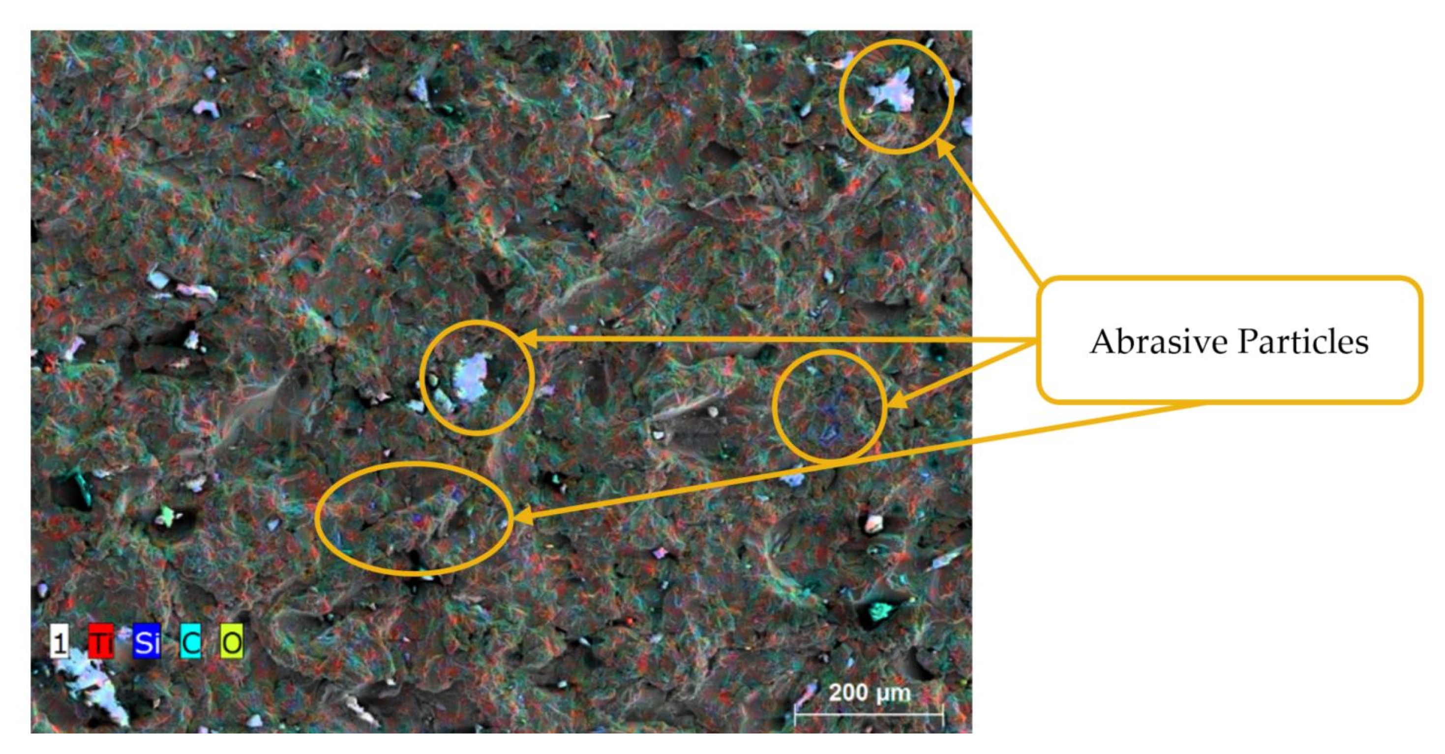
Abrasive water jet texturing can produce surfaces with a high roughness finish. But, due to the nature of the process and the high kinetic energy given to the abrasive particles, they can remain adhered to the surface as indicated in the results obtained by Rivero et al. [36] and Suarez et al. [41].
This is corroborated in Figure 3, where by means of EDS analysis and knowing the chemical composition of the abrasive particles used, the remains adhered to the surface after texturing can be observed.
Therefore, the surfaces obtained for all combinations of cutting parameters are shown in Figure 4. Thus, a cross feed of 0.1 mm results in a more homogeneous and visually less rough surface, as well as a larger amount of adhering abrasive particles.
On the contrary, by increasing the cross feed to 0.45 mm, the surface obtained is rougher, with larger cavities and a smaller amount of abrasive particles adhered in comparison.
For the same level of cross feed, an increase in traverse speed from 5000 to 9000 mm/min seems to generate a less rough surface with a smaller amount of particles adhering. This may be because, as the speed increases, the amount of water and abrasive particles impacting the surface decreases. This reduces the erosion capacity of the water jet, producing a less rough surface.
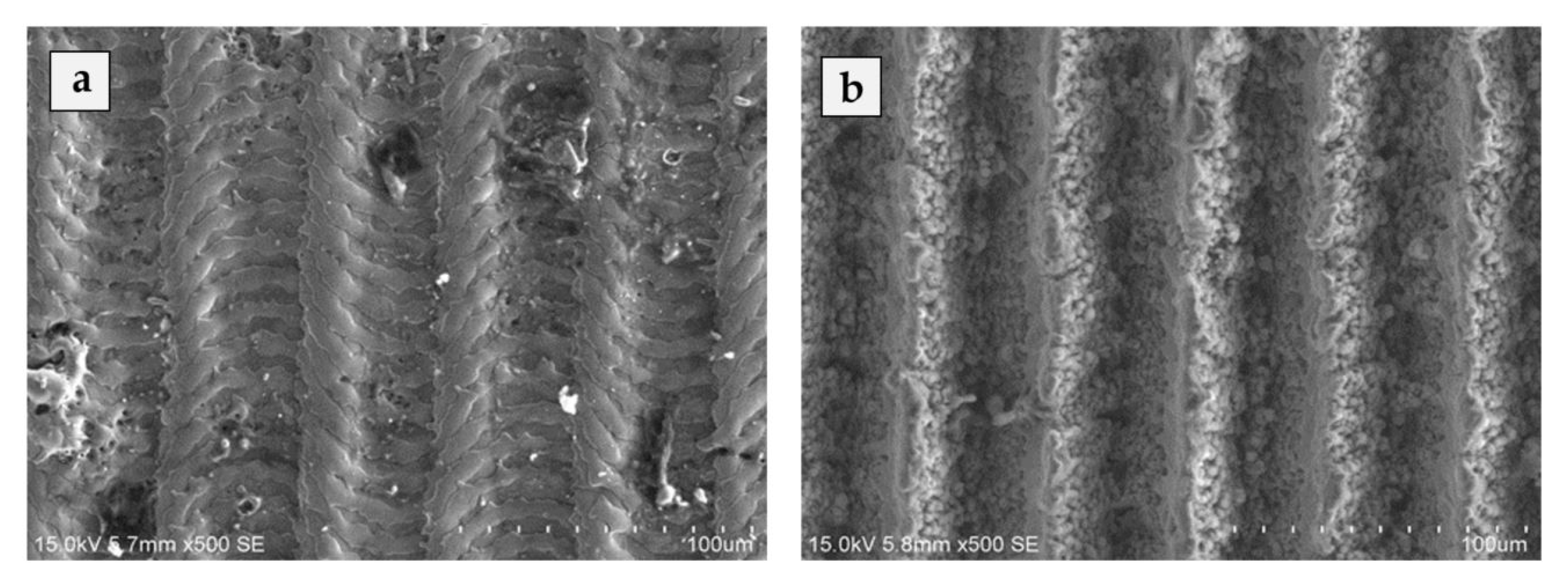
Surfaces obtained by laser surface texturing are shown in Figure 5. Figure 5a shows the surface obtained for a power of 5 W and a scanning speed of 250 mm/min and Figure 5b corresponds to a power of 20 W and a scanning speed of 100 mm/min.
Both surfaces have been obtained by applying a frequency of 20 kHz. In the first case, as it has such a low power, the laser beam modifies the surface without going deep into the material. This produces a rougher surface than non-textured steel, but with poorly defined grooves due to the reduced penetration capacity of the laser beam. This is consistent with the results obtained by Lawrence et al. [30] in which the surface quality obtained from a laser-textured carbon steel in terms of Ra is reduced by increasing the scanning speed from 250 to 2000 mm/min. This produces a reduction in laser energy, resulting in insufficient melting of the steel and a smoothing of the surface.
On the contrary, by increasing the power and reducing the time the laser beam travels over the surface, it is given a greater capacity for penetration. This produces more defined and deeper grooves that correspond to the passage of the laser during the texturing tests.

3.2. Surface Quality

The surface activation of metals is directly related to the surface quality obtained. A rougher surface, with large variations between the peaks and valleys generated, can therefore produce a better mechanical anchorage of subsequent adhesive joints.
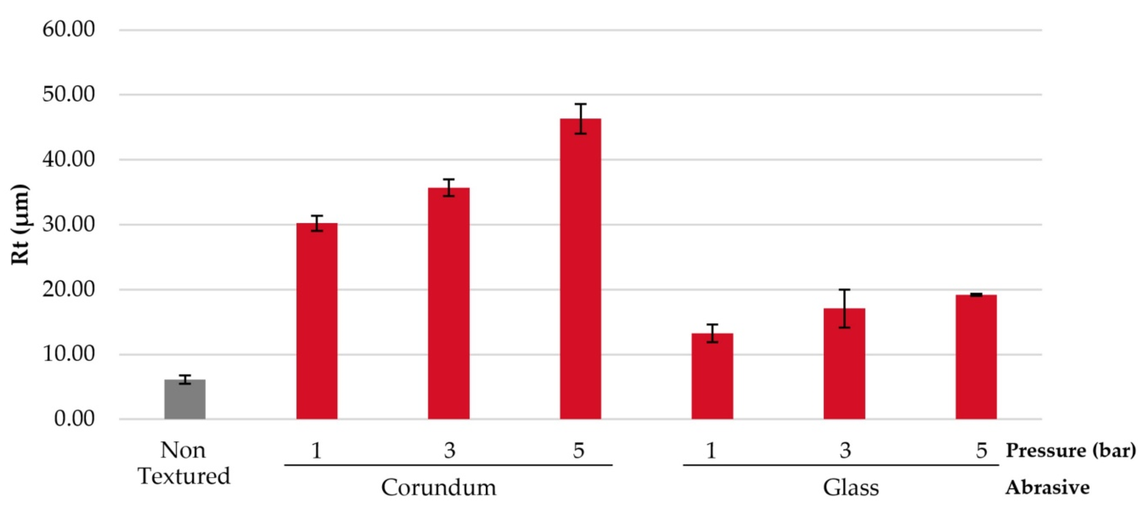
The surface quality of the samples obtained in terms of Rt for blasting is shown in Figure 6.
A different kind of abrasive particle is of great importance in order to generate a rougher surface. In the data obtained, the use of corundum particles generates Rt values twice as high as those of glass spheres. This is due to the geometry of the particles themselves. While glass particles are spherical, corundum particles have cutting edges, which are close to the geometry of the abrasive particles in the water jet. This allows the particles to remove a greater amount of material on impact with the surface, generating a rougher surface as indicated in the results of Santhanakrishnan et al. [32].
In addition, an increase in the pressure with which the particles impact on the surface increases their ability to tear off material and generate a rougher surface.
In comparison, the roughness generated by abrasive water jet texturing is shown in Figure 7. First of all, the Rt values obtained by this technology compared to shot blasting are remarkable. While for shot blasting, Rt values close to 45 µm were obtained for the best combination of parameters, abrasive water jet texturing generates values close to 60 µm.
Although both technologies are close in nature, the possibility of applying much higher pressure (800 bar) and a more homogeneous and constant particle distribution allows the generation of rougher surfaces.
This is also corroborated by the macrographs shown in Figure 5. The correct cross feed value is an essential parameter for generating a more homogeneous or rougher surface. While for a cross feed of 0.1 mm, the traverse speed does not influence the roughness generated, for cross feed of 0.3 mm and 0.45 mm, an increase in the traverse speed reduce the values of Rt.
This is because, by reducing the overlap of the jet between passes and reducing the amount of abrasive particles and water impacting the surface, the erosion generated is much lower, producing smaller craters due to the exposure and power density of the water jet are higher [35]. This is in line with the results obtained by Artaza et al. [34] where it indicates the importance a correct cross feed value to obtain a rougher surface in terms of Rt.
In addition, the overlap of the water jet is essential because, a very high overlap (cross feed of 0.1 mm) causes the jet to produce a homogeneous surface where the new run alters the surface generated by the previous run.
On the contrary, when this overlap is reduced (cross feed of 0.45 mm), this alteration is less, producing a greater variation in the surface itself, thus generating higher Rt values. This is corroborated by the ANOVA analysis shown in Table 5. Adj MS indicates the mean squares measure and how much variation a term or a model explains and Adj SS is the adjusted sums of squares are measures of variation for different components of the model. Additionally, the p-value is a probability that measures the evidence against the null hypothesis. Lower probabilities provide stronger evidence against the null hypothesis and higher values of F indicate a high influence on the response.
In this analysis, the most influential parameter in abrasive water jet texturing is the cross feed due to the overlapping of the jet itself on the material.
Surface quality generated by laser texturing is shown in Figure 8. From the results obtained, the trend that can be seen for the three powers applied stands out. On the one hand, the increase in the sweep speed reduces the penetration and modification capacity of the laser beam, producing a considerable decrease in the Rt values [1,30]. Finally, another outstanding parameter in the generation of a rough surface is the power applied to the laser. Thus, by giving it greater power, the penetration capacity of the laser increases and, in combination with a reduced sweep speed, allows the laser to eliminate a constant amount of material, generating very defined grooves [42].
This causes the peak values between peaks and valleys (Rt) to increase considerably. This is corroborated by the results obtained in the ANOVA analysis (Table 6).
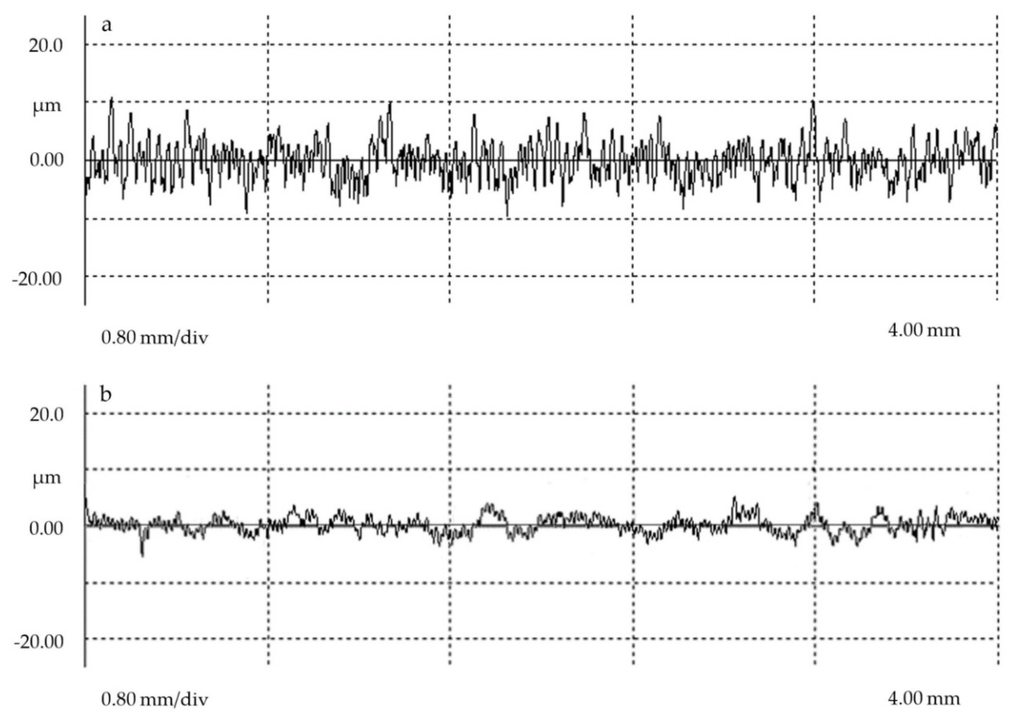
The most influential parameter is confirmed to be the sweep speed, followed by the power applied to the laser beam. This is consistent with the indications in [26]. A low energy applied to the laser beam in combination with a high sweep speed produces a lower peak and valley geometry (Figure 9), generating a lower Rt value and a more homogeneous surface.

3.3. Surface Free Energy

An essential parameter to determine the degree of activation of a surface is the Surface Free Energy. By means of the contact angle values when three liquids of different polarity are deposited on the textured surfaces and using Equation (1), the free surface energy of the surfaces obtained can be calculated. This parameter is directly related to the degree of adhesion of that surface. Thus, the free surface energy obtained for water jet texturing is shown in Figure 10.
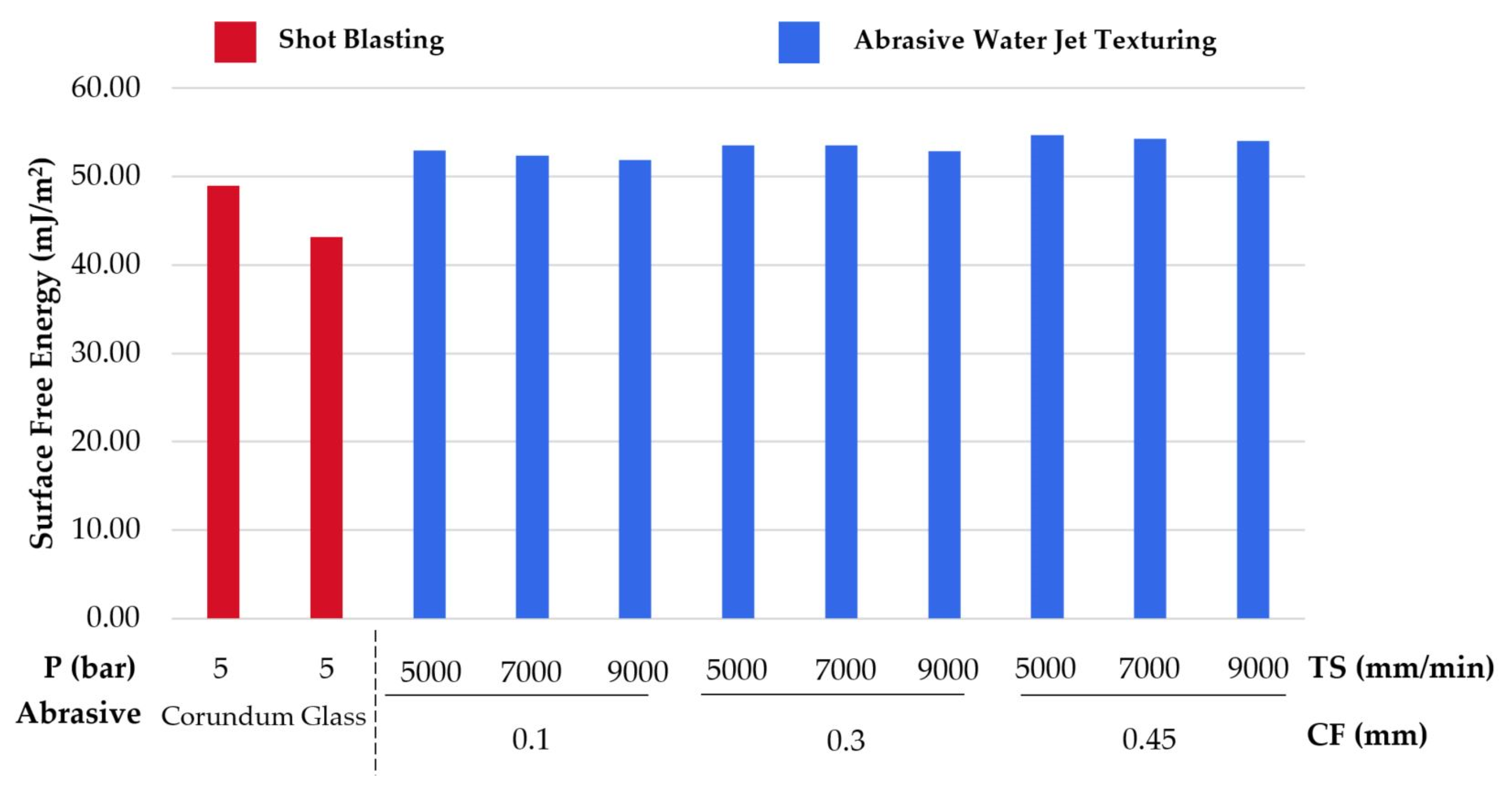
In comparison, it can be indicated that a higher Rt value is directly related to a higher surface free energy value for blasting and water jet texturing results. Water jet textured surfaces seem to offer values very close to each other. However, as with surface quality, an increase in blast gap and a travel speed of 5000 mm/min offer the highest values. Again, less jet overlap and more particles eroding the surface generate a higher roughness, allowing the liquid to expand over a larger area. This is confirmed by Figure 11 and Figure 12.
An increase in the contact angle of the drop deposited on the textured surface can be seen by increasing the speed of the water jet in Figure 11. The surface obtained is less rough, reducing its surface quality with Rt values of 59.63 µm to a Rt of 54.87 µm. This reduction between peaks and valleys generates a smaller distribution of cavities that prevent the liquid from expanding on the surface itself.
On the contrary, for a fixed traverse speed, a reduction in the overlap of the water jet corroborates the importance on the surface obtained (Figure 12).
Thus, the smaller the overlap (0.45 mm separation), the rougher the surface (Rt of 63.28 µm) and the smaller the contact angle. This means that there is a strong interaction between the surface of the substrate and the liquid drop (γSV > γSL). It should be noted that the surface free energy values generated by abrasive water jet texturing are higher than those obtained in blasting tests in other studies with values close to 30 mJ/m2 [32].
It can be indicated that, for abrasive water jet texturing, a correct combination of jet overlap with a travel speed of about 5000 mm/min offers the best surface in terms of wettability and adhesion capability. This is corroborated by the results obtained through an ANOVA analysis (Table 7).
Furthermore, compared to the best combination for each particle in shot blasting, both Rt and surface free energy values are higher in water jet texturing. This would indicate that this process is capable of obtaining rougher surfaces with a higher surface activation, reducing its surface tension and allowing better penetration of the liquid.
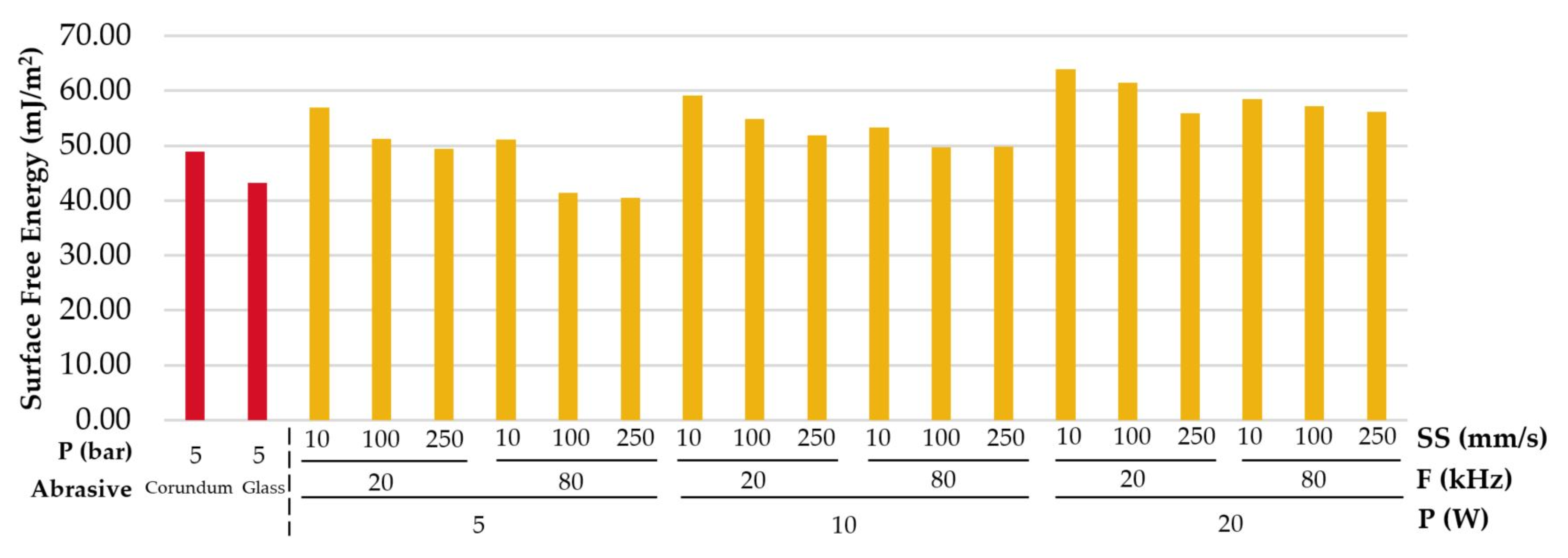
Free surface energy values obtained by laser texturing are shown in Figure 13. Once again, there is a relationship between surface quality (Rt) and the wettability of the surface obtained. For a fixed power of 5 W, the increase in the scanning speed generates less defined grooves, reducing the Rt values from 24.72 to 11.85 µm and generating a surface with a lower value of free surface energy. This means that the drop of liquid deposited on the surface has a more spherical geometry as it does not expand completely on the surface.
For the same sweeping speed, the increase of the power of the laser beam gives a greater capacity of penetration on the material, being able to melt more quantity and generating a rougher surface (Figure 14).
Therefore, an increase in the power of the laser beam with a reduced scanning speed produces more defined grooves and a rougher surface with higher peak and valley distances. This causes the deposited liquid to expand completely, reducing the contact angle and obtaining a hydrophilic surface. Although the Rt values obtained in laser texturing are lower than those obtained by water jet texturing, the surface obtained is more constant and defined due to the precision of the laser.
This allows the generation of more defined channels for a reduced scanning speed (Figure 15), allowing the liquid to expand. In contrast, a power of 5 W with a scanning speed of 250 mm/s produces a more homogeneous surface, generating a low strong interaction between the surface of the substrate and the drop of the liquid and increasing the contact angle.
The influence of these parameters is corroborated in the ANOVA analysis shown in the Table 8. The influence order on the surface free energy values is established with the most important parameters being the scanning power and speed as well as the surface quality. This is in line with what is indicated in [1] where, according on the power and scanning speed, the morphology generated in the metal after laser texturing varies considerably, generating hydrophilic or hydrophobic surfaces.

3.4. Contouring Diagrams

Due to the fact that only one quantitative parameter has been modified in the blasting tests (Pressure), no contour diagrams or ANOVA analysis have been obtained. However, the influence of the pressure on the roughness obtained is demonstrated, obtaining the maximum values of Rt for a pressure of 5 bar. In turn, corundum particles, due to their cutting geometry, generate rougher surfaces with higher values of surface free energy.
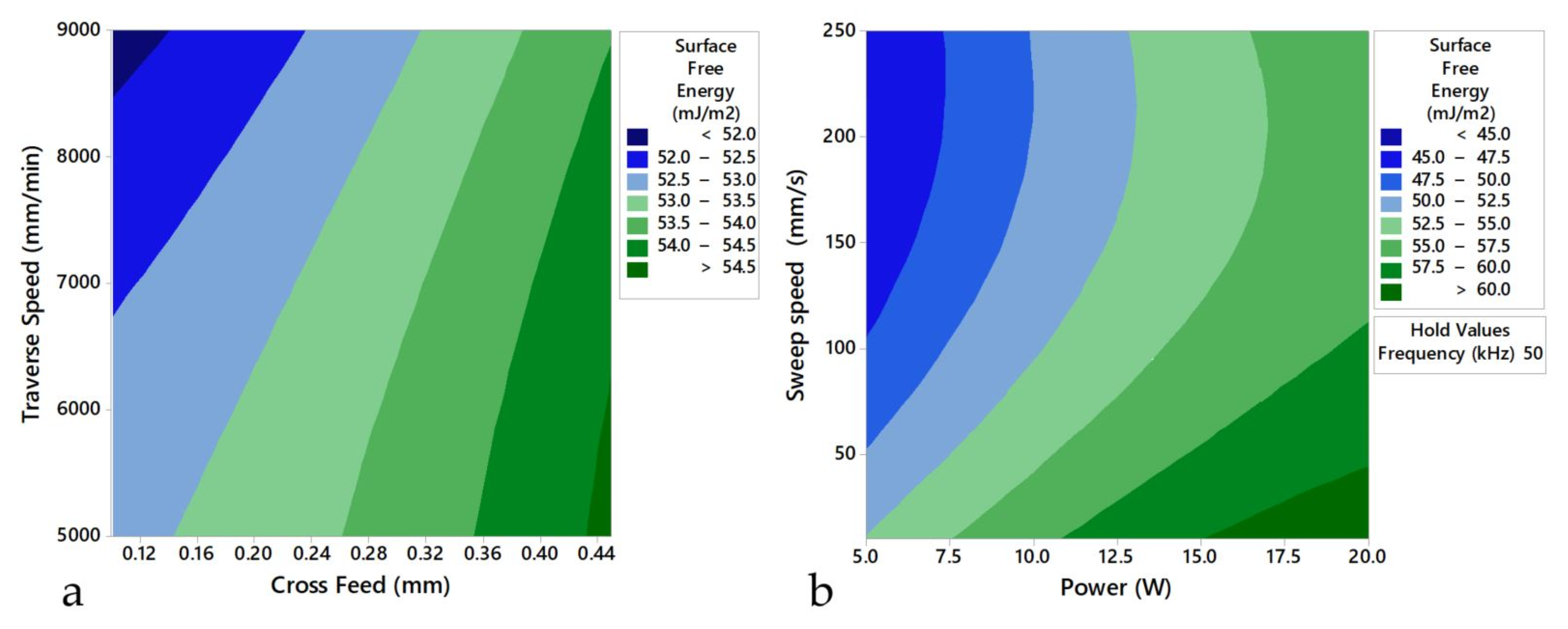
Figure 16 shows the contour diagrams for the surface free energy values obtained by abrasive water jet texturing and laser texturing. Both technologies obtain very close high values, being the technology that offers a better result the laser texturing due to the precision of the laser when modifying the surface. However, water jet texturing offers very close values for the variables studied. In turn, the maximum water jet speed of 9000 mm/min (150 mm/s) offers results between 52 to 54 mJ/m2 and a larger texturing area per pass compared to the results obtained by laser texturing for the same speed, with surface free energy values between 45 and 52.5 mJ/m2 and a smaller texturing area per pass.
In the same way, Figure 17 shows the contour diagrams corresponding to the surface qualities obtained in terms of Rt for the water jet and laser texturing tests. The influence of the cross feed on the Rt values is once again appreciated. Obtaining values close to 64 µm with a separation of 0.45 mm compared to 52 µm for a separation of 0.1 mm. Furthermore, the similarity of results obtained for the same combinations of parameters between surface quality and surface free energy can be appreciated. In this way, the relationship between these variables is corroborated, with a higher value of Rt indicating a higher value of free surface energy and a better adhesion capacity.

4. Conclusions

Surface activation of metals as an operation to reduce wear, improve tribological properties or joint operations between dissimilar materials is a line of research of great current interest.
Shot blasting, abrasive water jet texturing and laser surface texturing technologies have been applied and compared to an s275 carbon steel in order to establish a relationship between surface quality in terms of Rt and surface activation in terms of surface free energy.
In all three technologies, an increase in Rt values has been found to produce rougher surfaces with more defined cavities that allow the deposited liquids to penetrate and expand across the surface increasing the surface free energy values.
Shot blasting produces a surface similar to that obtained by water jet texturing. It has been determined that an increase in pressure produces a greater capacity for erosion in the particles by increasing the Rt values. In turn, corundum particles generate a rougher surface due to their geometry compared to glass spheres.
Abrasive water jet texturing produces surfaces with the highest Rt values of the three technologies used. The importance of the cross feed and the choice of a traverse speed close to 5000 mm/min is highlighted. This produces a greater erosion when the particles impact on the surface, producing more defined cavities and increasing surface activation in terms of free surface energy. However, it has been verified that these particles can remain adhered to the surface itself.
More defined surface patterns have been obtained by laser surface texturing. In the results obtained, the influence of the power and the sweep speed of the laser beam has been verified by reducing the contact angle values and producing a greater surface activation. At the same time, by generating more defined and deeper channels, it allows a greater surface lubrication by allowing the liquids to expand completely over the surface. In addition, an increase in frequency seems to worsen the surface obtained. A power of 20 W with a frequency of 20 kHz and a sweep speed of 10 mm/s obtains the best results in terms of surface free energy.
Finally, a set of contour diagrams have been obtained for surface quality and abrasive water jet texturing in which they are related to the main texturing parameters. In addition, the relationship between surface quality and surface activation is established.

Author Contributions

F.B. and A.S. developed machining tests. M.B. and J.S. developed data treatment. F.B., A.S., M.B., B.S. and J.S. analyzed the influence of the parameters involved. F.B. and A.S. collaborated in preparing figures and tables and F.B., A.S., M.B., B.S., and J.S. wrote the paper. All authors have read and agreed to the published version of the manuscript.

Funding

This work has been developed under support of a pre-doctoral industrial fellow financed by NANOTURES SL, mechanical engineering and industrial design department and Vice-rectorate of Transference and Technological Innovation of the University of Cadiz.

Conflicts of Interest

The authors declare no conflict of interest.

References

  1. Vazquez-Martinez, J.M.; Gomez, J.S.; Ares, P.F.M.; Fernandez-Vidal, S.R.; Ponce, M.B. Effects of laser microtexturing on the wetting behavior of Ti6Al4V alloy. Coatings 2018, 8, 145. [Google Scholar] [CrossRef] [Green Version]
  2. Li, H.; Liu, X.S.; Zhang, Y.S.; Ma, M.T.; Li, G.Y.; Senkara, J. Current Research and Challenges in Innovative Technology of Joining Dissimilar Materials for Electric Vehicles. In Proceedings of the 4th International Conference on Advanced High Strength Steel and Press Hardening (ICHSU2018), Hefei, China, 20–22 August 2018; pp. 363–380. [Google Scholar]
  3. Almagro, S.C. Thermoplastic/Metal Composite Bonding in the Field of Transport. Available online: https://e-archivo.uc3m.es/handle/10016/16395 (accessed on 21 February 2020).
  4. Pramanik, A.; Basak, A.K.; Dong, Y.; Sarker, P.K.; Uddin, M.S.; Littlefair, G.; Dixit, A.R.; Chattopadhyaya, S. Joining of carbon fibre reinforced polymer (CFRP) composites and aluminium alloys – A review. Compos. Part A Appl. Sci. Manuf. 2017, 101, 1–29. [Google Scholar] [CrossRef] [Green Version]
  5. McCombe, G.P.; Etches, J.A.; Mellor, P.H.; Bond, I.P. Development of a ferromagnetic fibre metal laminate. Compos. Part A Appl. Sci. Manuf. 2011, 42, 1380–1389. [Google Scholar] [CrossRef]
  6. Xu, J.; El Mansori, M. Experimental study on drilling mechanisms and strategies of hybrid CFRP/Ti stacks. Compos. Struct. 2016, 157, 461–482. [Google Scholar] [CrossRef] [Green Version]
  7. Reincke, T.; Hartwig, S.; Dilger, K. High-tensile joints of continuously fusion bonded hybrid structures. Compos. Struct. 2017, 202, 111–118. [Google Scholar] [CrossRef]
  8. Pahuja, R.; Ramulu, M. Abrasive water jet machining of Titanium (Ti6Al4V)—CFRP stacks—A semi-analytical modeling approach in the prediction of kerf geometry Abrasive water jet machining of Titanium (Ti6Al4V)—CFRP stacks—A semi-analytical modeling approach in the pre. J. Manuf. Process. 2019, 39, 327–337. [Google Scholar] [CrossRef]
  9. Fernandez-Vidal, S.; Fernandez-Vidal, S.; Batista, M.; Salguero, J. Tool Wear Mechanism in Cutting of Stack CFRP/UNS A97075. Materials 2018, 11, 1276. [Google Scholar] [CrossRef] [Green Version]
  10. Samaei, M.; Zehsaz, M.; Chakherlou, T.N. Experimental and numerical study of fatigue crack growth of aluminum alloy 2024-T3 single lap simple bolted and hybrid (adhesive/bolted) joints. Eng. Fail. Anal. 2016, 59, 253–268. [Google Scholar] [CrossRef]
  11. Zhang, K.; Yang, Z.; Li, Y. A method for predicting the curing residual stress for CFRP/Al adhesive single-lap joints. Int. J. Adhes. Adhes. 2013, 46, 7–13. [Google Scholar] [CrossRef]
  12. Hamilton, C.; Węglowski, M.S.; Dymek, S. A Simulation of Friction-Stir Processing for Temperature and Material Flow. Metall. Mater. Trans. B Process Metall. Mater. Process. Sci. 2015, 46, 1409–1418. [Google Scholar] [CrossRef]
  13. Sheng, L.; Jiao, J.; Du, B.; Wang, F.; Wang, Q. Influence of Processing Parameters on Laser Direct Joining of CFRTP and Stainless Steel. Adv. Mater. Sci. Eng. 2018, 2018, 1–15. [Google Scholar] [CrossRef] [Green Version]
  14. Biron, M. Outline of the actual situation of plastics compared to conventional materials. In Thermoplastics and Thermoplastic Composites; William Andrew: Norwich, NY, USA, 2018; pp. 1–32. ISBN 9780081025017. [Google Scholar]
  15. Ishikawa, T.; Amaoka, K.; Masubuchi, Y.; Yamamoto, T.; Yamanaka, A.; Arai, M.; Takahashi, J. Overview of automotive structural composites technology developments in Japan. Compos. Sci. Technol. 2018, 155, 221–246. [Google Scholar] [CrossRef]
  16. Masek, P.; Zeman, P.; Kolar, P. Edge trimming of C/PPS plates. Int. J. Adv. Manuf. Technol. 2018, 101, 157–170. [Google Scholar] [CrossRef] [Green Version]
  17. Jiao, J.; Xu, Z.; Wang, Q.; Sheng, L.; Zhang, W. CFRTP and stainless steel laser joining: Thermal defects analysis and joining parameters optimization. Opt. Laser Technol. 2018, 103, 170–176. [Google Scholar] [CrossRef]
  18. Rakgate, S.M.; Dundu, M. Effectiveness of Surface Preparation on the Capacity of Plated Reinforced Concrete Beams. Structures 2018, 14, 348–357. [Google Scholar] [CrossRef]
  19. Rudawska, A. Surface treatment methods. Surf. Treat. Bond. Technol. 2019, 47–62. [Google Scholar]
  20. Al-Rousan, R.Z.; AL-Tahat, M.F. Consequence of surface preparation techniques on the bond behavior between concrete and CFRP composites. Constr. Build. Mater. 2019, 212, 362–374. [Google Scholar] [CrossRef]
  21. Rudawska, A.; Danczak, I.; Müller, M.; Valasek, P. The effect of sandblasting on surface properties for adhesion. Int. J. Adhes. Adhes. 2016, 70, 176–190. [Google Scholar] [CrossRef]
  22. Arifvianto, B.; Suyitno; Mahardika, M. Effect of sandblasting and surface mechanical attrition treatment on surface roughness, wettability, and microhardness distribution of AISI 316L. Key Eng. Mater. 2011, 462–463, 738–743. [Google Scholar] [CrossRef]
  23. Silva, M.A.G.; Biscaia, H.; Ribeiro, P. On factors affecting CFRP-steel bonded joints. Constr. Build. Mater. 2019, 226, 360–375. [Google Scholar] [CrossRef]
  24. Vazirinasab, E.; Jafari, R.; Momen, G. Application of superhydrophobic coatings as a corrosion barrier: A review. Surf. Coatings Technol. 2018, 341, 40–56. [Google Scholar] [CrossRef]
  25. Wojciechowski, L.; Kubiak, K.J.; Mathia, T.G. Roughness and wettability of surfaces in boundary lubricated scuffing wear. Tribol. Int. 2016, 93, 593–601. [Google Scholar] [CrossRef] [Green Version]
  26. Vazquez Martinez, J.; Del Sol Illana, I.; Iglesias Victoria, P.; Salguero, J. Assessment the Sliding Wear Behavior of Laser Microtexturing Ti6Al4V under Wet Conditions. Coatings 2019, 9, 67. [Google Scholar] [CrossRef] [Green Version]
  27. Rudawska, A. Assessment of surface preparation for the bonding/adhesive technology. In Surface Treatment in Bonding Technology; Elsevier: Amsterdam, The Netherlands, 2019; pp. 227–275. ISBN 9780128170106. [Google Scholar]
  28. Yuan, Y.; Lee, T.R. Contact Angle and Wetting Properties. In Springer Series in Surface Sciences; Springer: Heidelberg/Berlin, Germany, 2013; ISBN 978-3-642-34242-4. [Google Scholar]
  29. Campos Bernardes, P.; Andrade Araújo, E.; dos Santos Pires, A.C.; Felício Queiroz Fialho, J.; Aparecida Lelis, C.; de Andrade, N.J. Work of adhesion of dairy products on stainless steel surface. Brazilian J. Microbiol. 2012, 43, 1261–1268. [Google Scholar] [CrossRef] [PubMed] [Green Version]
  30. Lawrence, J.; Li, L. Carbon steel wettability characteristics enhancement for improved enamelling using a 1.2 kW high power diode laser. Opt. Lasers Eng. 1999, 32, 353–365. [Google Scholar] [CrossRef] [Green Version]
  31. Islam, M.S.; Tong, L.; Falzon, P.J. Influence of metal surface preparation on its surface profile, contact angle, surface energy and adhesion with glass fibre prepreg. Int. J. Adhes. Adhes. 2014, 51, 32–41. [Google Scholar] [CrossRef]
  32. Santhanakrishnan Balakrishnan, V.; Obrosov, A.; Kuke, F.; Seidlitz, H.; Weiß, S. Influence of metal surface preparation on the flexural strength and impact damage behaviour of thermoplastic FRP reinforced metal laminate made by press forming. Compos. Part B Eng. 2019, 173, 1–10. [Google Scholar] [CrossRef]
  33. Sambruno, A.; Bañon, F.; Salguero, J.; Simonet, B.; Batista, M. Kerf Taper Defect Minimization Based on Abrasive Waterjet Machining of Low Thickness Thermoplastic Carbon Fiber Composites C/TPU. Materials 2019, 12, 4192. [Google Scholar] [CrossRef] [Green Version]
  34. Artaza, T.; Alberdi, A.; Olite, J.; Latapia, J.L.; Gil, D.; Suarez, A.; Rivero, A. Abrasive Waterjet Texturing as a Method to Enhance the Embedment of Metallic Inserts in Composite Materials. Procedia Eng. 2015, 132, 724–731. [Google Scholar] [CrossRef] [Green Version]
  35. Pahuja, R.; Ramulu, M.; Hashish, M. Integration of jetting technology in metal additive manufacturing. In Proceedings of the 24th International Conference on Water Jetting, Manchester, UK, 5–7 September 2018; pp. 23–35. [Google Scholar]
  36. Rivero, A.; Alberdi, A.; Artaza, T.; Mendia, L.; Lamikiz, A. Surface properties and fatigue failure analysis of alloy 718 surfaces milled by abrasive and plain waterjet. Int. J. Adv. Manuf. Technol. 2018, 94, 2929–2938. [Google Scholar] [CrossRef]
  37. Linghoff, D.; Haghani, R.; Al-Emrani, M. Carbon-fibre composites for strengthening steel structures. Thin-Walled Struct. 2009, 47, 1048–1058. [Google Scholar] [CrossRef]
  38. Baillie, P.; Campbell, S.W.; Galloway, A.M.; Cater, S.R.; McPherson, N.A. A Comparison of Double Sided Friction Stir Welding in Air and Underwater for 6mm S275 Steel Plate. World Acad. Sci. Eng. Technol. 2014, 8, 759–763. [Google Scholar]
  39. Lam, A.C.C.; Cheng, J.J.R.; Yam, M.C.H.; Kennedy, G.D. Repair of steel structures by bonded carbon fibre reinforced polymer patching: Experimental and numerical study of carbon fibre reinforced polymer - Steel double-lap joints under tensile loading. Can. J. Civ. Eng. 2007, 34, 1542–1553. [Google Scholar] [CrossRef]
  40. Gilbert, N. Structural Steel - S235, S275, S355 Chemical Composition, Mechanical Properties and Common Applications. AZO Mater. 2012, 1, 1–5. [Google Scholar]
  41. Suárez, A.; Veiga, F.; Polvorosa, R.; Artaza, T.; Holmberg, J.; de Lacalle, L.N.L.; Wretland, A. Surface integrity and fatigue of non-conventional machined Alloy 718. J. Manuf. Process. 2019, 48, 44–50. [Google Scholar] [CrossRef]
  42. Dursun, G.; Ibekwe, S.; Li, G.; Mensah, P.; Joshi, G.; Jerro, D. Influence of laser processing parameters on the surface characteristics of 316L stainless steel manufactured by selective laser melting. Mater. Today Proc. 2020, in press. [Google Scholar] [CrossRef]
Figure 1. Measurement process and evaluation of contact angle on textured surfaces: (a) equipment used for contact angle measurement; (b) Drop deposition procedure on textured surfaces; (c) Contact angle measurement by image processing software.
Metals 10 00290 g001
Figure 2. Metallography at 10x of the surfaces obtained for: (a) Shot blasting (Corundum particles); (b) Non-textured; (c) AWJT; (d) Laser Power 5 W; (e) Laser Power 20 W.
Metals 10 00290 g002
Figure 3. Remains of abrasive particles adhered to the surface after texturing.
Metals 10 00290 g003
Figure 4. SEM images of abrasive waterjet textured surfaces at 60× for: (a) 0.1 mm and 5000 mm/min; (b) 0.1 mm and 7000 mm/min; (c) 0.1 mm and 9000 mm/min; (d) 0.3 mm and 5000 mm/min; (e) 0.3 mm and 7000 mm/min; (f) 0.3 mm and 9000 mm/min; (g) 0.45 mm and 5000 mm/min; (h) 0.45 mm and 7000 mm/min; (i) 0.45 mm and 9000 mm/min.
Metals 10 00290 g004
Figure 5. SEM imaging of laser-textured surfaces at 500× for: (a) 5 W and 250 mm/s; (b) 20 W and 10 mm/s.
Metals 10 00290 g005
Figure 6. Rt values obtained in blasting tests.
Metals 10 00290 g006
Figure 7. Rt values obtained in abrasive water jet textured tests.
Metals 10 00290 g007
Figure 8. Rt values obtained in laser textured tests.
Metals 10 00290 g008
Figure 9. Roughness profiles obtained for: (a) 5 W and 10 mm/s; (b) 5 W and 250 mm/s.
Metals 10 00290 g009
Figure 10. Surface free energy values for water jet texturing tests.
Metals 10 00290 g010
Figure 11. Increase of the contact angle for a separation of 0.3 mm and: (a) 5000 mm/min; (b) 7000 mm/min; (c) 9000 mm/min.
Metals 10 00290 g011
Figure 12. Contact angle reduction for a traverse speed of 7000 mm/min and: (a) 0.1 mm; (b) 0.3 mm; (c) 0.45 mm.
Metals 10 00290 g012
Figure 13. Surface free energy values for laser texturing tests.
Metals 10 00290 g013
Figure 14. Surface differences obtained by laser texturing at 20×: (a) 5 W and 250 mm/s; (b) 20 W and 10 mm/s.
Metals 10 00290 g014
Figure 15. Contact angles obtained in laser texturing for: (a) 5 W and 250 mm/s; (b) 20 W and 10 mm/s.
Metals 10 00290 g015
Figure 16. Contour diagrams of the surface free energy values obtained for: (a) Abrasive water jet texturing; (b) Laser texturing.
Metals 10 00290 g016
Figure 17. Contour diagrams of the surface quality obtained for: (a) Abrasive water jet texturing; (b) Laser surface texturing.
Metals 10 00290 g017
Table 1. Chemical composition and mechanical properties of s275 steel.
%C%Fe%Mn%P%S%Si
0.2598.011.600.040.050.05
Yield Strength (MPa)Tensile Strength (MPa)Thickness (mm)
2754503
Table 2. Experimental design for abrasive water jet texturing.
Traverse Speed (mm/min)Cross Feed (mm)
5000–7000–90000.1–0.3–0.45
Table 3. Experimental design for laser texturing.
Power-P (W)Frequency-F (kHz)Sweep Speed-SS (mm/s)
5–10–2020–8010–100–250
Table 4. Polar and dispersive components of the liquids used for the calculation of the free surface energy.
Deposited Liquids γ L V (mJ/m2) γ L V d (mJ/m2) γ L V p (mJ/m2)
Distilled water72.821.851.0
Diiodomethane50.850.80.0
Ethylene glycol47.730.916.0
Table 5. ANOVA analysis of the surface quality obtained in abrasive water jet texturing.
SourceDFAdj SSAdj MSF-ValueP-Value
Model5215.60843.12219.970.016
Cross Feed1199.911199.91192.590.002
Traverse Speed17.8117.8113.620.153
Cross Feed*Cross Feed14.7124.7122.180.236
Traverse Speed*Traverse Speed10.3590.3590.170.711
Cross Feed*Traverse Speed15.6825.6822.630.203
Error36.4782.159--
Total8222.086---
* multiplication symbol for the modified varia.
Table 6. ANOVA analysis of the surface quality obtained in laser texturing.
SourceDFAdj SSAdj MSF-ValueP-Value
Model8660.24982.5317.160.004
Power1125.207125.20710.870.009
Frequency151.91251.9124.500.063
Sweep speed1354.666354.66630.780.000
Power*Power175.28575.2856.530.031
Sweep speed*Sweep speed18.5638.5630.740.411
Power*Frequency160.54860.5485.250.048
Power*Sweep speed12.7082.7080.230.639
Frequency*Sweep speed115.62415.6241.360.274
Error9103.71411.524--
Total17763.963---
Table 7. ANOVA analysis of the free surface energy obtained in abrasive water jet texturing.
SourceDFAdj SSAdj MSF-ValueP-Value
Model56.848131.3696361.090.003
Cross Feed15.757795.75779256.810.001
Traverse Speed11.050751.0507546.870.006
Cross Feed*Cross Feed10.052290.052292.330.224
Traverse Speed*Traverse Speed10.019380.019380.860.421
Cross Feed*Traverse Speed10.039160.039161.750.278
Error30.067260.02242
Total86.91539
Table 8. ANOVA analysis of the free surface energy obtained in laser texturing.
SourceDFAdj SSAdj MSF-ValueP-Value
Model8605.39675.67520.100.000
Power1327.522327.52287.000.000
Frequency1104.062104.06227.640.001
Sweep speed1119.177119.17731.660.000
Power*Power15.5765.5761.480.255
Sweep speed*Sweep speed116.95216.9524.500.063
Power*Frequency116.31816.3184.330.067
Power*Sweep speed13.9613.9611.050.332
Frequency*Sweep speed13.9833.9831.060.33.0
Error933.8833.765
Total17639.279