Abstract
A quantitative feeding system of molten metal was designed based on a special vehicle cover, which achieved the quantitative transport of molten metal in a fully enclosed environment. There are lots of advantages of this novel device, such as improving the accuracy of the molten metal pouring, reducing the oxide inclusions defects, improving the quality of forming parts, etc. The numerical simulation of the casting process of filling mold was carried out based on the software ProCAST, which optimized the processing parameters of the quantitative feeding device. The result shows that the optimal movement speed of the punch piston is 0.08 m/s. The forming process of the aluminum alloy cover was designed and the process was conducted on the novel quantitative feeding device of molten metal. The structure and process performance of the forming parts were summarized and the defects were analyzed. The influence of technological parameters such as pouring temperature, filling speed, initial mold temperature, and feeding distance on the quality of forming parts was studied, which resulted in the optimum process parameters for the dosing device.
1. Introduction
Aluminum (Al) alloy materials are widely used in mechanical industries due to their excellent characteristics such as low density and high strength [1,2,3], and excellent physical properties and mechanical properties can be obtained through heat treatments. The traditional casting process of Al alloy restricts the production efficiency due to the difficulty of controlling the process precision and the poor quality of produced parts [4]. Currently, the squeeze casting process is widely used in the automobile, aerospace, and military fields due to its high quality, low cost, and easy management [5,6,7]. Squeeze casting, also known as liquid die forging, is a process for obtaining a part or a blank, which directly injects molten metal or semi-solid alloy into an open mold. Then, the mold closes to apply a clamping force on the molten metal, and the unsolidified metal is subjected to isostatic pressing to produce a forced feeding. The solidified metal (outer shell) is plastically deformed, and high-pressure solidification occurs at the same time [4,8,9,10,11]. The squeeze casting process usually consists of three procedures: (1) mold preparation and liquid metal pouring, (2) mold clamping and pressing, and (3) the mold opening and demolding [12,13,14]. As a near net forming process for light metal, squeeze casting combines the advantages of casting and forging, indicating low production cost, fewer casting defects, and reliable quality [15,16,17].
The pouring of molten liquid metal is the vital process in squeeze casting, as well as the key point which limits the development of squeeze casting. The traditional pouring process is hand-cast by workers, resulting in high labor intensity and poor working environment [18,19]. It is difficult to accurately control the flow rate due to manual pouring, causing poor dimensional accuracy of the casting product. On the other hand, due to the long period exposure of molten metal in air, defects such as oxide inclusions are caused, which have a negative effect on product quality [20,21]. Therefore, improving the flow accuracy and automation of the molten metal casting process is of vital importance to the development of squeeze casting equipment [22]. The enclosed die-casting system “LEOMACS” designed by Toshiba machines, combining magnetic pump injection for molten metal with indirect metal forging, improved not only the production efficiency but also the product quality [23,24]. A metal transfer tube delivering molten magnesium to a die casting machine (Courtesy of Metamag, Inc., Strathroy, ON, Canada) was employed in magnesium casting technology, as reported by Luo, which effectively prevented the molten magnesium from oxidation [25]. In Yu et al.’s work, a molten metal transfer system was designed to investigate the interfacial heat transfer behavior at the metal/shot sleeve interface in the high-pressure die casting process of AZ91D alloy [26]. The shot sleeve was implemented with three blocks of thermocouples in the bottom side along the direction of movement of plunger to collect temperature readings at the metal–sleeve interface.
In this work, a metal liquid quantitative feeding system was designed and further improved, which achieved the quantitative transport of molten metal in a fully enclosed environment, improving the accuracy of the molten metal pouring, reducing the oxide inclusion defects, and improving the quality of forming parts. The forming process of the 7075 Al alloy cover was designed, and the process was conducted on a novel quantitative feeding device. The optimum process parameters were obtained via a numerical simulation based on the software ProCAST and the analysis of sample properties.
2. Experiment
The composition of 7075 Al alloy (provided by NORTHEAST LIGHT ALLOY Co., Ltd., Harbin, China) used in this work is shown in Table 1. Figure 1 shows the Al alloy liquid metal quantitative feeding device, which connected the molten liquid metal and the forming hydraulic pressure machine, and which achieved the automatic quantitative transportation of the liquid metal. The feeding process of liquid metal was carried out in a fully enclosed device, avoiding contact with air and reducing defects such as oxidation and spatter of liquid flow. At the same time, the liquid metal was pressed by the main punch at a constant speed, and subsequently injected smoothly into the mold cavity, avoiding air entrapment and liquid flow splashing. Later, through the programmable logic controller (PLC), the entire squeeze casting process was automated, and the production efficiency was effectively improved. The simulation of the liquid metal filling process was carried out using the software ProCAST (version 2009.1, UNIVERSAL ENERGY SYSTEM).

Table 1.
Composition of 7075 Al alloy (wt.%).
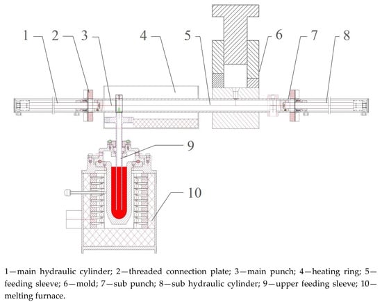
Figure 1.
Quantitative feeding system device for squeeze casting forming.
In the forming process, the 7075 Al alloy blank was placed in a well-type melting furnace for melting, and a certain amount of Al alloy refining agent (hexachloroethane, purchased from Aladdin, Shanghai, China) was added during the melting to remove impurities contained in the blank. The initial temperature of the liquid metal pouring was controlled at 700–740 °C. The ceramic heating ring was used to heat and maintain the temperature of the feeding sleeve, and the local temperature of the feeding sleeve was heated to 450 °C to reduce the heat loss of the liquid metal during the transport process. The forming mold shown in Figure 2 was heated and insulated by a heating rod with a power of 2 kW, and the heating temperature was set to 100–300 °C. When the mold temperature reached 100 °C, the grease graphite lubricant (purchased from QingDao KunYu Graphite products Co., Ltd., Qingdao, China) was sprayed on the surface of the upper and lower molds in order to facilitate demolding. The distance between the upper mold and the limit plate, known as the feeding distance, was controlled by adjusting the disc spring rod. The feeding distance was 0 mm when the upper mold contacted the limit plate, and the feeding distance was set to 0–4 mm in the forming experiment.
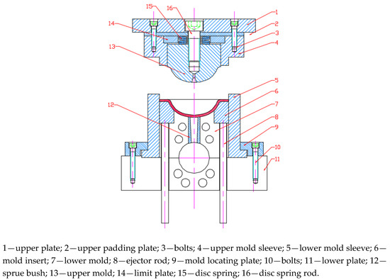
Figure 2.
Schematic of forming mold.
After being poured into feeding sleeve, the liquid metal was pushed by the main punch and injected into the mold cavity at a certain movement rate. The movement rate of the main punch was simulated and determined by the software ProCAST. The simplified model, surface mesh, and solid mesh are shown in Figure 3. The adaptive meshing method was adopted to mesh the geometry model. After meshing, the total number of elements was 621,054. The mesh size was set as 5 mm. The interface type was set as the “COINC (coincident)” mode and the interfacial heat-transfer coefficient was set as 3000 W/(m2∙K). The thermophysical parameters of the 7075 Al alloy are given in Table 2. The hydropress was controlled to make the upper mold move downward at a speed of 30 mm/s. The upper mold first contacted the liquid metal, pushing the liquid metal to the flange. As the upper mold continued to descend, the upper mold sleeve acted on the liquid metal, and the upper mold moved up to achieve the partial filling at the end of forming. Until the upper mold contacted the limit plate, the forming pressure was completely applied on the sample with a dwell time of 20 s. Then, the remaining metal in the feeding sleeve fell from the discharge opening as the main punch advanced and the sub punch drew back. At last, the punch returned stroke, and the ejector rods ejected the forming sample out of the concave mold to complete the squeeze casting of the 7075 Al alloy cover. The experimental schematic is shown in Table 3.
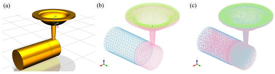
Figure 3.
Simplified model (a), surface mesh (b), and solid mesh (c).
Table 2.
Thermophysical parameters of the 7075 Al alloy.
Table 3.
Experimental schematic.
The characteristic points were distributed in the bottom, side wall, and flange of the prepared cover. Therefore, the metallographic samples were chosen from the three characteristic positions, and the sample size was 15 mm × 15 mm × 4 mm. The metallographic samples were ground using 100#, 500#, 1000#, 1500#, and 2000# sandpaper. After grinding, the polishing treatment and etching treatment were conducted. The etching agent was self-mixed 2.5% HNO3-1.5% HCl-1% HF aqueous solution, and the etching time was set as 20 s. The microstructure was analyzed using a metallographic microscope (Olympus-PEM-3, Tokyo, Japan). Tensile test specimens with an effective stretch length of 13 mm were cut from the flange and bottom of the cover. Then, the heating treatments were conducted on the tensile specimen. For the solution treatment, the specimens were heated at 490 °C ± 5 °C for 2 h followed by water quenching; For the aging treatment, the specimens after solution treatment were heated at 190 ± 5 °C for 9 h, and then air-cooled. Tensile tests at room temperature were carried out using an electronic universal testing machine (AG-Xplus250kN, SHIMADZU, Kyoto, Japan) at the tensile rate of 1.5 mm/min. The tensile fracture of the sample was observed by a scanning electron microscope (SEM, Merlin Compact, ZEISS, Oberkochen, Germany) to further explore the fracture mechanism.
3. Results and Discussion
3.1. Determination of the Rate of Punch Movement
The horizontal movement rate of the punch is the vital process parameter for designing a metal liquid quantitative feeding device. If the movement rate is too slow, the liquid metal cooling time is long in the feeding sleeve, the fluidity becomes lower, and the solidification occurs even before the mold cavity is filled, resulting in blocking in the feeding sleeve. Conversely, if the movement rate of the punch is too fast, the liquid metal splashes easily when the liquid metal enters the mold cavity, which increases the inclination of defects such as oxidation of the gas. Therefore, the punch should push the liquid metal at a uniform rate, thereby smoothly filling the mold cavity and reducing the occurrence of defects.
Due to the limited power of the hydraulic system, the maximum advancement speed of the main punch was 0.1 m/s. Therefore, the speeds were set as 0.02 m/s, 0.04 m/s, 0.06 m/s, 0.08 m/s, and 0.10 m/s during the simulation. Under the guiding principle of reducing the cooling time as much as possible, the fastest movement rate of 0.1 m/s was selected. When the punch movement rate was set as 0.1 m/s, the metal liquid pouring temperature was 700 °C, the initial mold temperature was 200 °C, and the screenshot step was a 20% filling rate. According to the analysis of the cloud image (Figure 4), when the main punch movement rate was 0.1 m/s, the metal liquid uniformly filled the mold cavity. When the filling rate reached about 50%, the metal liquid began to enter the cover flange from the side wall; at the same time, a slight entrapment of air occurred at the front of liquid flow, which lead to defects in the samples. Therefore, the punch movement rate needs to be less than 0.1 m/s.
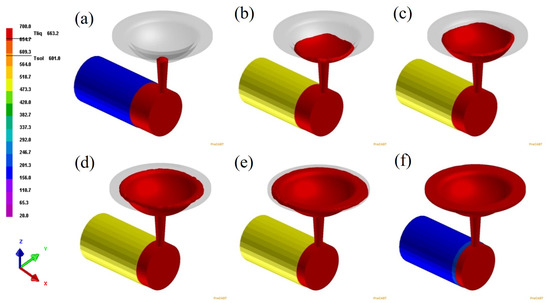
Figure 4.
Temperature cloud diagrams for different filling rates when the punch movement rate was 0.1 m/s: (a) 0%; (b) 20%; (c) 40%; (d) 60%; (e) 80%; (f) 100%.
The main punch movement rate was set as 0.08 m/s, the metal liquid pouring temperature was 700 °C, the initial mold temperature was 200 °C, and the screenshot step was a 20% filling rate. The cloud images (Figure 5) shows that the metal liquid entered the mold cavity smoothly throughout the filling process, and there was no obvious entrapment of air or liquid-flow splashing. Therefore, the punch movement rate of 0.08 m/s was determined as the optimum process parameter.
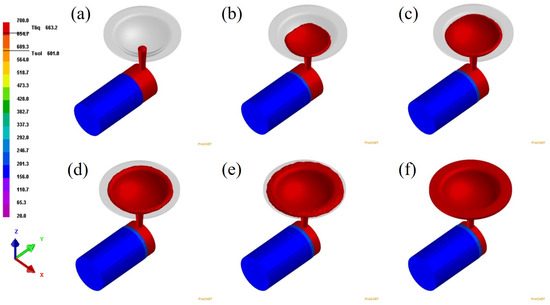
Figure 5.
Temperature cloud diagrams for different filling rates when the punch movement rate was 0.08 m/s: (a) 0%; (b) 20%; (c) 40%; (d) 60%; (e) 80%; (f) 100%.
3.2. Macroscopic Morphology Analysis of Formed Parts
Figure 6 shows the macroscopic morphology of the formed parts. As shown in Figure 6a, the cold shut and misrun defects were observed, which could be ascribed to the fluidity of liquid metal being too poor to fill the mold cavity sufficiently during the filling process, resulting in the incomplete formation of parts and the occurrence of defects. In order to fill the mold cavity sufficiently, the process parameters should be adjusted accordingly. The thermal insulation of metal liquid was ensured during the delivery process, the rate of the main punch was appropriately adjusted to between 0.08 m/s and 0.1 m/s, and the dwell time was elongated.
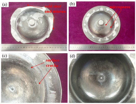
Figure 6.
Macroscopic morphology of formed parts: (a) cold shut and misrun; (b) micropores; (c) surface cracks; (d) surface with no defects.
During the forming process, pores and cracks could be observed on the surface of formed parts, as shown in Figure 6b. The semi-spherical pores exhibited different sizes and smooth walls. When the upper mold moved downward and contacted with metal liquid, excessive impact force caused the gas to be trapped in the liquid flow, and the gas could not come out due to the short dwell time, which resulted in porosity surface defects. In order to avoid the occurrence of such defects, the downward speed of the upper mold was controlled during the process, and the dwell time was adjusted to guarantee that the gas could completely discharge from the mold cavity.
The surface crack defects are depicted in Figure 6c. A tear-like crack surface and metal oxidation could be observed, indicating that the crack was a thermal crack. When the metal liquid entered the mold cavity, the heat was lost mainly through the molds and, thus, the metal liquid adjacent to the surface of the part firstly solidified. As the metal liquid solidified, a large number of dendrites continuously overlapped to form a skeleton, and the metal liquid began to shrink, while there was also unsolidified metal liquid between the dendrite skeletons. Since the metal mold lacked deformability, the inner stress in the formed part increased due to the large cooling rate. Tensile stress was generated since the shrinkage of dendritic skeleton was hindered by inner stress. When the tensile stress exceeded the material strength limitation, cracks formed between the dendrites could not be replenished by the metal liquid in a timely manner. In view of the thermal crack, the dwell time was adjusted to make sure that the metal liquid could continuously be pushed to fill the porosity caused by the shrinkage during the solidification process. The overlapped dendrites were broken and the inner stress caused by the shrinkage of the dendritic skeleton could be released. Figure 6d shows the formed parts after adjusting the process parameters, which demonstrated that surfaces of the cover parts were relatively smooth, and no defects such as cracks, hook grooves, and wrinkles were observed.
3.3. Effects of Pouring Temperature on Microstructure and Properties of Formed Parts
Figure 7 shows the metallographic photographs of the cover flanges at different pouring temperatures. The crystal grains with a cell-like crystal morphology were coarse, showing an uneven size distribution, when the pouring temperature was 700 °C. As the pouring temperature increased, the nucleation rate of the metal liquid increased, and the grain size was refined at the pouring temperature of 710 °C. Small grain agglomerations around the large grains could be observed. When the metal liquid pouring temperature reached 720 °C, the grain morphology and size distribution were relatively uniform, and the metal liquid nucleation rate reached the highest, resulting in crystal grains with small and dense morphology. When the pouring temperature continued to be elevated, the grain size increased, and the morphology distribution became uneven.
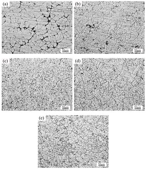
Figure 7.
Metallographic photographs of the cover flange at different pouring temperatures: (a) 700 °C; (b) 710 °C; (c) 720 °C; (d) 730 °C; (e) 740 °C.
The yield strength and tensile strength of the samples taken from the flange at different pouring temperatures are shown in Figure 8a. The yield strength and tensile strength were the lowest, i.e., 305.4 MPa and 346.5 MPa, respectively, when the pouring temperature of the metal liquid was 700 °C. As the pouring temperature increased, the yield strength tended to increase and became stable. The initial tensile strength rose rapidly and decreased slightly in the later stage. The maximum yield strength was 340.4 MPa at 730 °C, and the maximum tensile strength was 367.4 MPa at 720 °C.
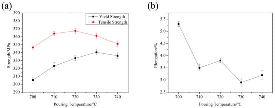
Figure 8.
Strength and elongation of the samples at different casting temperatures: (a) strength; (b) elongation.
The elongations of the samples taken from the flange at different pouring temperatures are shown in Figure 8b. When the pouring temperature was in the range of 700–740 °C, the plasticity of the sample fluctuated. With the increase in pouring temperature, the elongation varied slightly. At the pouring temperature of 700 °C, the sample had the highest elongation of 5.3%, and the lowest elongation was 2.9% at the pouring temperature of 730 °C. The elongation fluctuated within the range of 0.8% in the pouring temperature range.
3.4. Effect of Mold Pre-Heating Temperature on Microstructure and Properties of Formed Parts
Figure 9 shows the metallographic photographs of the cover flanges at different pre-heating temperatures of the mold. In the process, the movement rate of the main punch was 0.08 m/s, the pouring temperature was 730 °C, and the feeding distance was 2 mm. When the mold pre-heating temperature was 100 °C, there were a large number of coarse grains with uneven distribution of grain sizes. As the pre-heating temperature of the mold increased, the grain became finer and denser. Finer grains with uniform distribution were observed as the mold pre-heating temperature increased to 200–250 °C. When the pre-heating temperature of the mold was 300 °C, the grain demonstrated the tendency of growth. In addition, if the mold temperature was too high, the slow cover cooling rate resulted in grain coarsening. Thus, the optimum pre-heating temperature of the mold was set as 200–250 °C under the conditions of the test forming equipment.
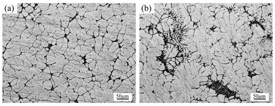
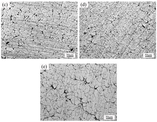
Figure 9.
Metallographic photographs of the samples at different mold pre-heating temperatures: (a) 100 °C; (b) 150 °C; (c) 200 °C; (d) 250 °C; (e) 300 °C.
The yield strength and tensile strength of the samples taken from the flange at different pre-heating temperatures of mold are shown in Figure 10a. When the mold pre-heating temperature was 100 °C, the yield strength and tensile strength were the lowest, i.e., 290.4 MPa and 325.5 MPa, respectively. The strength of the formed part firstly increased and then decreased as the pre-heating temperature of the mold increased. The yield strength and tensile strength reached the maximum of 340.4 MPa and 361.7 MPa, respectively, at the mold pre-heating temperature of 250 °C. As the mold pre-heating temperature was elevated continually, the strength of the formed part tended to decrease.
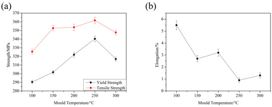
Figure 10.
Strength and elongation of the samples at different mold pre-heating temperatures: (a) strength; (b) elongation.
Figure 10b shows the elongations of the tensile specimen at different pre-heating temperatures of the mold. The elongation of the sample was 5.5% at most when the mold temperature was 100 °C. As the pre-heating temperature of the mold increased, the elongation certainly fluctuated. The elongation of the samples exhibited an obvious downward trend when the mold pre-heating temperature was elevated to 200 °C, which could be ascribed to the grain growth at a high mold temperature resulting in a decrease in plasticity. When the mold temperature was 250 °C, the elongation was reduced to the lowest value.
3.5. Effect of Feeding Distance on Microstructure and Properties of Formed Parts
The metallographic photographs of the cover flanges with different feeding distances are shown in Figure 11. The process conditions were as follows: the movement rate of the main punch was 0.08 m/s, the pouring temperature was 730 °C, and the initial mold temperature was 250 °C. The microstructure was loose without feeding, and coarse grains with uneven distribution were observed. As the feeding distance increased, the grains became dense and refined. When the feeding distance was 3 mm or 4 mm, the grain size was relatively small, and the distribution was uniform.
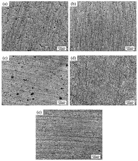
Figure 11.
Metallographic photographs of the samples with different feeding distances: (a) 0 mm; (b) 1 mm; (c) 2 mm; (d) 3 mm; (e) 4 mm.
Figure 12 shows the yield strength and elongation of the samples taken from the flange with different feeding distances. As the feeding distance increased, the yield strength and tensile strength of the samples increased. When the feeding distance exceeded 2 mm, the strength tended to be stable. The elongation of the samples varied with the feeding distance. The elongation was 5.2% at most when the feeding distance was 0 mm, and the elongation was at least 0.9% with the feeding distance of 4 mm. As the feeding distance increased, the elongation of the sample decreased. Combined with metallographic analysis, the mechanical properties were closely related to the microstructure characteristics. The samples with a denser and finer grain demonstrated considerable strength.
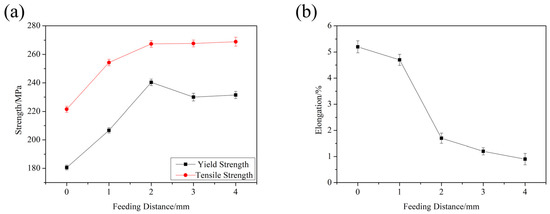
Figure 12.
Strength and elongation of the samples with different feeding distances: (a) strength; (b) elongation.
3.6. Analysis of Microstructure and Properties at Different Position of Formed Parts
The process conditions were as follows: the pouring temperature of the metal liquid was 730 °C, the movement rate of the main punch was 0.08 m/s, the pre-heating temperature of the mold was 250 °C, and the holding time was 20 s. The metallographic photographs of the samples taken from the flange, side wall, and bottom of the formed parts are shown in Figure 13. There were significant differences among the microstructure at these three locations. The grains at the flange were flat and spherical, and they had an uneven size distribution, while shrinkage micro-holes could also be observed. The grains at the side wall were relatively coarser, demonstrating a more uneven distribution, and there was nucleation of microcracks, thereby reducing the service life of the forming parts. The grains at the bottom of the formed parts had a small size and fuzzy boundary. A dense structure was observed in the samples subjected to plastic deformation, but there were also numerous shrinkage micro-holes.
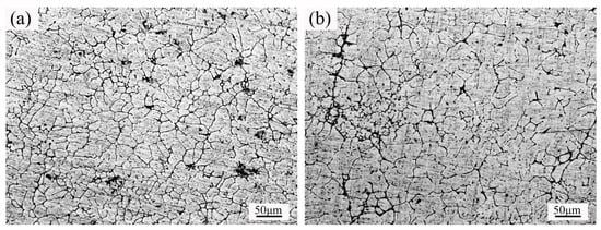
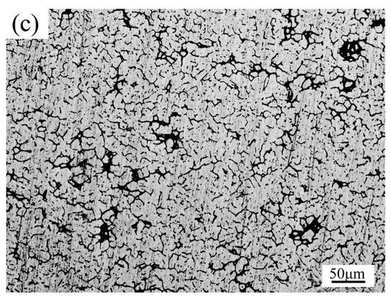
Figure 13.
Metallographic photographs of the samples at different position of forming parts: (a) flange; (b) side wall; (c) bottom.
The yield strength and tensile strength of the samples taken from the flange and the bottom are shown in Figure 14. The average yield strength and the average tensile strength at the flange were 342.8 MPa and 367.3 MPa, respectively. The average yield strength and the average tensile strength at the bottom were 317.3 MPa and 345.2 MPa, respectively. The elongations of different samples at different positions are shown in Figure 15. The average elongation at the flange was 1.6%, and the average elongation at the bottom was 2.1%. The comparison indicated that the mechanical properties at the bottom were poorer than those at the flange. Specifically, the yield strength was about 10.5% lower, the tensile strength was about 8.3% lower, and the elongation was about 2.3% lower. The molten metal filled the mold through the bottom of the cover, and it was easy to form shrinkage holes due to lacking of feeding. When stretching, these shrinkage holes would evolve into a crack nucleation site, which would reduce the strength of the forming parts.
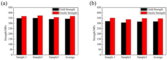
Figure 14.
Strength of the samples in different positions: (a) flange; (b) bottom.
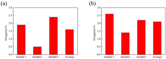
Figure 15.
Elongation of the samples in different positions: (a) flange; (b) bottom.
3.7. Analysis of Tensile Fracture Behavior
Figure 16 shows the fracture morphology of the samples formed under the following process conditions: the movement rate of the main punch was 0.08 m/s, the pouring temperature was 730 °C, the initial mold temperature was 250 °C, and the feeding distance was 2 mm. As shown in Figure 16a, a small number of cleavage steps and numerous pores could be found in the fractured morphology due to incomplete feeding, which caused the molten metal to shrink during solidification. Considerably equiaxed dimples and microscopic pores could be observed at position A as shown in Figure 16b. At position B, there were a large number of tearing dimples caused by the fracture across the grain. When the sample was stretched and deformed, some holes formed. As the deformation progressed, the micro-holes expanded at the minimum cross-sectional area of the necking, and cracks formed gradually. With the cracks expanding, more holes were congested, and a fibrous region formed in the fracture morphology. When the cracks approached the free surface of the sample, the sample underwent plastic deformation, which resulted in instability and rapid propagation of the cracks. Above all, the cover samples demonstrated a ductile intergranular fracture.
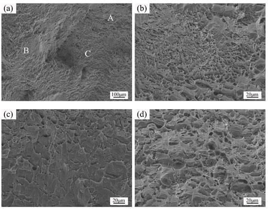
Figure 16.
SEM micrographs of tensile fracture specimen: (a) whole area; (b) position A; (c) position B; (d) position C.
4. Conclusions
A metal liquid quantitative feeding system was designed and improved, which could achieve the quantitative transport of molten metal in a fully enclosed environment, improving the accuracy of the molten metal pouring, reducing the oxide inclusions defects, and improving the quality of forming parts. The forming process of the Al alloy cover was designed, and the process was conducted on the novel quantitative feeding device of molten metal. The optimum punch movement rate was 0.08 m/s obtained via the numerical simulation carried out using software ProCAST. When the pouring temperature was 730 °C, the initial mold temperature was 250 °C, and the feeding distance was 2 mm, whereas the average yield strength and the average tensile strength at the flange were 342.8 MPa and 367.3 MPa, respectively. The average yield strength and the average tensile strength at the bottom were 317.3 MPa and 345.2 MPa, respectively. The average elongation at the flange was 1.6%, and the average elongation at the bottom was 2.1%. When the sample was stretched and deformed, the main fracture mode was ductile intergranular fracture.
Author Contributions
Conceptualization, G.C. and Z.D.; methodology, Y.Q.; software, L.C.; validation, Y.Q., G.C. and Z.D.; formal analysis, K.L.; investigation, C.L.; resources, Z.D.; data curation, G.C.; writing—Original draft preparation, Y.Q.; writing—Review and editing, Y.Q.; visualization, C.L.; supervision, L.C.; project administration, L.C.; funding acquisition, G.C. All authors have read and agreed to the published version of the manuscript.
Funding
This research was funded by National Natural Science Foundation of China, grant number 51875121 and Natural Science Foundation of Shandong Province, grant number ZR2019MEE039.
Conflicts of Interest
The authors declare no conflict of interest.
References
- Thangapandian, N.; Prabu, S.B.; Padmanabhan, K.A. Effect of Temperature on Grain Size in AA6063 Aluminum Alloy Subjected to Repetitive Corrugation and Straightening. Acta. Metall. Sin. (Engl. Lett.) 2019, 32, 835–844. [Google Scholar] [CrossRef]
- Brabazon, D.; Browne, D.J.; Carr, A.J. Mechanical stir casting of aluminium alloys from the mushy state: Process, microstructure and mechanical properties. Mater. Sci. Eng. A. 2002, 326, 370–381. [Google Scholar] [CrossRef]
- Guan, R.G.; Zhao, Z.Y.; Li, Y.D.; Chen, T.J.; Xu, S.X.; Qi, P.X. Microstructure and properties of squeeze cast A356 alloy processed with a vibrating slope. J. Mater. Process. Technol. 2016, 229, 514–519. [Google Scholar] [CrossRef]
- Zheng, C.K.; Zhang, W.W.; Zhang, D.T.; Li, Y.Y. Low cycle fatigue behavior of T4-treated Al-Zn-Mg-Cu alloys prepared by squeeze casting and gravity die casting. Nonferr. Metal. Soc. 2015, 25, 3505–3514. [Google Scholar] [CrossRef]
- Sarfraz, M.H.; Jahanzaib, M.; Ahmed, W.; Hussain, S. Multi-response parametric optimization of squeeze casting process for fabricating Al 6061-SiC composite. Int. J. Adv. Manuf. Technol. 2019, 102, 759–773. [Google Scholar] [CrossRef]
- Chen, G.; Chang, X.; Zhang, J.; Jin, Y.; Sun, C.; Chen, Q.; Zhao, Z. Microstructures and Mechanical Properties of In-Situ Al3Ti/2024 Aluminum Matrix Composites Fabricated by Ultrasonic Treatment and Subsequent Squeeze Casting. Met. Mater. Int. 2019. [Google Scholar] [CrossRef]
- Timelli, G.; Fabrizi, A.; Vezzù, S.; De Mori, A. Design of Wear-Resistant Diecast AlSi9Cu3(Fe) Alloys for High-Temperature Components. Metals 2019, 10, 55. [Google Scholar] [CrossRef]
- Maleki, A.; Niroumand, B.; Shafyei, A. Effects of squeeze casting parameters on density, macrostructure and hardness of LM13 alloy. Mater. Sci. Eng. A. 2006, 428, 135–140. [Google Scholar] [CrossRef]
- Fang, X.G.; Lu, S.L.; Zhao, L.; Wang, J.; Liu, L.F.; Wu, S.S. Microstructure and mechanical properties of a novel Mg-RE-Zn-Y alloy fabricated by rheo-squeeze casting. Mater. Design. 2016, 94, 353–359. [Google Scholar] [CrossRef]
- Uozumi, H.; Kobayashi, K.; Nakanishi, K.; Matsunaga, T.; Shinozaki, K.; Sakamoto, H.; Tsukada, T.; Masuda, C.; Yoshida, M. Fabrication process of carbon nanotube/light metal matrix composites by squeeze casting. Mater. Sci. Eng. A. 2008, 495, 282–287. [Google Scholar] [CrossRef]
- Yang, J.; Chen, D.; Long, M.; Duan, H. An Approach for Modelling Slag Infiltration and Heat Transfer in Continuous Casting Mold for High Mn–High Al Steel. Metals 2019, 10, 51. [Google Scholar] [CrossRef]
- You, D.D.; Wang, X.; Cheng, X.Y.; Jiang, X.M. Friction modeling and analysis of injection process in squeeze casting. J. Mater. Process. Technol. 2017, 239, 42–51. [Google Scholar] [CrossRef]
- Jeong, S.I.; Jin, C.K.; Seo, H.Y.; Kim, J.D.; Kang, C.G. Mould Design for Clutch Housing Parts using a Casting Simulation of High Pressure Die Casting. Int. J. Precis. Eng. Man. 2016, 17, 1523–1531. [Google Scholar] [CrossRef]
- Youn, S.W.; Kang, C.G.; Seo, P.K. thermal fluid/solidification analysis of automobile part by horizontal squeeze casting process and experimental evaluation. J. Mater. Process. Technol. 2004, 146, 294–302. [Google Scholar] [CrossRef]
- Liu, T.; Wang, Q.D.; Sui, Y.D.; Wang, Q.G. Microstructure and Mechanical Properties of Overcast 6101-6101 Wrought Al Alloy Joint by Squeeze Casting. J. Mater. Sci. Technol. 2016, 32, 298–304. [Google Scholar] [CrossRef]
- Vijayaram, T.R.; Sulaiman, S.; Hamouda, A.M.S.; Ahmad, M.H.M. Fabrication of fiber reinforced metal matrix composites by squeeze casting technology. J. Mater. Process. Technol. 2006, 178, 34–38. [Google Scholar] [CrossRef]
- Huang, M.; Zhang, G.; Wang, D.; Dong, J.S.; Wang, L.; Lou, L.H. Microstructure and Stress-Rupture Property of Large-Scale Complex Nickel-Based Single Crystal Casting. Acta. Metall. Sin. (Engl. Lett.) 2018, 31, 887–896. [Google Scholar] [CrossRef]
- Chen, G.; Li, J.T.; Xu, G.M. Bonding process and interfacial reaction in horizontal twin-roll casting of steel/aluminum clad sheet. J. Mater. Process. Technol. 2017, 246, 1–12. [Google Scholar] [CrossRef]
- Souissi, N.; Souissi, S.; Lecompte, J.P.; Ben Amar, M.; Bradai, C.; Halouani, F. Improvement of ductility for squeeze cast 2017 A wrought aluminum alloy using the Taguchi method. Int. J. Adv. Manuf. Technol. 2015, 78, 2069–2077. [Google Scholar] [CrossRef]
- Laibinis, P.E.; Whitesides, G.M. Self-Assembled Monolayers of N-Alkanethiolates on Copper Are Barrier Films That Protect the Metal against Oxidation by Air. J. Am. Chem. Soc. 1992, 114, 9022–9028. [Google Scholar] [CrossRef]
- Papworth, A.; Fox, P. Oxide film casting defects in squeeze cast metal matrix composites. Mater. Lett. 1996, 29, 209–213. [Google Scholar] [CrossRef]
- Chua, C.K.; Chew, T.H.; Eu, K.H. Integrating rapid prototyping and tooling with vacuum casting for connectors. Int. J. Adv. Manuf. Technol. 1998, 14, 617–623. [Google Scholar]
- Ghomashchi, M.R.; Vikhrov, A. Squeeze casting: An overview. J. Mater. Process. Technol. 2000, 101, 1–9. [Google Scholar] [CrossRef]
- Toshiba Machine. Available online: https://www.toshiba-machine.co.jp/en/index.html (accessed on 7 January 2020).
- Luo, A.A. Magnesium casting technology for structural applications. J. Magnes. Alloy. 2013, 1, 2–22. [Google Scholar] [CrossRef]
- Yu, W.B.; Cao, Y.Y.; Li, X.B.; Guo, Z.P.; Xiong, S.M. Determination of Interfacial Heat Transfer Behavior at the Metal/Shot Sleeve of High Pressure Die Casting Process of AZ91D Alloy. J. Mater. Sci. Technol. 2017, 33, 52–58. [Google Scholar] [CrossRef]


© 2020 by the authors. Licensee MDPI, Basel, Switzerland. This article is an open access article distributed under the terms and conditions of the Creative Commons Attribution (CC BY) license (http://creativecommons.org/licenses/by/4.0/).