Abstract
The work is devoted to the study of the laws of the formation of a hydride rim in E110 zirconium alloy claddings during gas-phase hydrogenation. The problem of hydrogen penetration and accumulation and the subsequent formation of hydrides in the volume of zirconium cladding tubes of water-cooled power reactors remain relevant. The formation of brittle hydrides in a zirconium matrix firstly, leads to a significant change in the mechanical properties, and secondly, can cause the destruction of the claddings by the mechanism of delayed hydride cracking. The degree of the hydride’s effect on the mechanical properties of zirconium cladding is mainly determined by the features of the hydride’s distribution and orientation. The problem of hydride rim formation in zirconium alloys with niobium is quite new and poorly studied. Therefore, the study of hydride rim formation in Russian zirconium alloy is important and necessary for predicting the behavior of claddings during the formation of the hydride rim.
1. Introduction
Zirconium alloys are widely used in nuclear reactors [1,2,3,4,5], as zirconium alloys possess a low thermal neutron capture cross-section; they are characterized by corrosion resistance, good strength properties, and resistance to radiation damage. Fuel cladding, grid assembly, and fuel channels are produced from zirconium alloys in reactors. The E110 (Zr1%Nb) alloy is used in Russia’s reactors to produce fuel cladding, while Zircaloy-2 (Zr1.5%Sn0.12%Fe0.1%Cr0.05%Ni0.13%O) and Zircaloy-4 (Zr1.55%Sn0.22%Fe0.12%Cr0.12%O0.015%C0.01%Si) alloys have been used internationally for these purposes since the middle of the previous century.
Among one of the main requirements of zirconium fuel cladding is low hydrogen absorption capacity, since, under certain conditions, absorbed hydrogen causes embrittlement and consequent destruction in compliance with the mechanism of delayed hydride cracking, which may result in a loss of sealing [6,7,8,9,10]. Hydrogen solubility in zirconium alloys at room temperature does not exceed 1 × 10⁻⁵ wt.% while at an operational temperature (~350 °C). This value is in the range of 2 × 10⁻² wt.%. With the exceedance of the hydrogen solubility limit in zirconium alloys, the formation of hydride phases takes place; the latter causes the greatest embrittlement, as hydrides possess significantly lower plasticity in comparison with zirconium. Furthermore, hydrides in the zirconium matrix can serve as the locations for crack initiation, followed by a subsequent crack opening [11,12,13] and the formation of through-the-thickness damage.
The effect of hydrogen on the mechanical properties of zirconium alloys is mainly determined by its amount, as well as by the hydride’s orientation and localization. Hydrides located in the bulk of zirconium cladding have a minimal effect on the mechanical properties of zirconium cladding. However, frequently, fuel cladding hydrogenation occurs nonuniformly, and local clusters of hydrides take place on the outer surface of the cladding. The formation of hydrides on the outer surface of the cladding leads to the degradation and destruction of the mechanical properties by a delayed hydride cracking mechanism [7,8,9].
During the operation in water-cooled power reactors and pressurized water reactors (PWR) in zirconium fuel claddings, the gradient of hydrogen concentration through the cladding wall thickness and hydride initiation is formed, accompanied by hydride rim formation. Formation of the hydride layer with the thickness of 50–100 µm takes place on the outer surface of the fuel cladding; the hydride layer thickness depends on the degree of hydrogenation [14,15,16,17,18,19].
The degree of the zirconium alloy’s hydrogenation significantly depends on the reactor’s operational state or the parameters of hydrogenation (in the laboratory settings). One of the most commonly used methods for zirconium alloy’s saturation with hydrogen is the gas-phase hydrogenation method. This method’s key parameter, which effects the hydrogen’s interaction behavior with the materials, is the temperature. The other parameters’ values remain unchanged; the hydrogenation temperature value is the determinant in hydride rim formation. The works [18,19] demonstrated that during hydrogenation—under the temperature lower than determined—the threshold temperature in the formation of the hydride rim in fuel cladding from Zircaloy-2 and Zircaloy-4 alloys takes place. During hydrogenation at the temperatures higher than the threshold temperature, the formation of a hydride rim does not take place. In this respect, there is a necessity to determine the threshold temperature of gas-phase hydrogenation that enables the formation of the hydride rim in E110 alloy fuel claddings developed for the Russian water-cooled nuclear reactors.
Another factor that affects the degree of the zirconium alloy’s hydrogenation is their surface state—namely, oxide film [20,21]. Zirconium alloy surfaces, coated with homogeneous thin oxide film, absorb hydrogen weakly, even at high temperatures [22]. On the one hand, the presence of such oxide film plays a positive role in the operating conditions, as it reduces hydrogen permeability. On the other hand, there is a necessity to prepare the experimental samples of zirconium alloys with different hydrogen concentrations and distributions for prospective research purposes (e.g., to conduct mechanical testing). In experimental samples, preparation of the oxide film will hinder hydrogenation and make it impossible in a number of cases where the temperature volume is limited (e.g., when preliminary thermal treatment of the material takes place). Thus, it becomes relevant to investigate the methods of increasing hydrogen permeability in zirconium alloys.
The technology of ion-beam cleaning of the alloy’s surface with subsequent nickel coating can be applied to increase hydrogen permeability of zirconium alloys. Ion-beam cleaning allows the removal of oxide film, while nickel coating performed immediately after cleaning prevents rapid oxide film formation. Furthermore, nickel is an alloying element that facilitates hydrogen absorption due to the suppression of hydrogen atomic recombination in molecules [23,24]. Zirconium alloy surface cleaning will lead to an increase of the hydrogen absorption rate; in turn, the latter will cause changes in the values of the threshold temperature of hydride rim formation.
Due to this, the goal of the present research is to establish behavior and determine the conditions for hydride rim formation in the E110 alloy cladding tubes during gas-phase hydrogenation. The formation of the hydride rim in the Russian zirconium alloy E110 has not been previously studied. The relevance of the work is primarily due to the need to develop a technique that will allow, under controlled conditions, the preparation of samples of E110 zirconium alloy with a hydride rim for further mechanical tests.
2. Materials and Research Methods
The test material is the cladding tubes Ø 9.5 × 8.33 mm (batch # 5080-12-02/4-4) made from an E110 (Zr1%Nb) zirconium alloy based on sponge and produced in compliance with TC 001.411-2009 (cold-rolled seamless tubes for fuel claddings for PWR reactors); the cladding tubes were provided by A.A. Bochvar High-technology Scientific Research Institute of Inorganic Materials in the delivery condition.
The studies of microstructure were performed using an Olympus GX 51 optical microscope (Tokyo, Japan). The studies of microstructure were performed with a light field test and demonstrated the uniformly distributed inclusions of the second phases in the alloy matrix, without clusters, and having an oval shape. The studies performed in the polarized light demonstrated that, when subjected to finish annealing, all the tubes possess a recrystallized structure with an equiaxed grain shape. The average grain size is within the range of 2.8–3.7 µm. The minimum grain size is 0.6–1.4 µm, while the maximum grain size, taking into consideration their conglomeration due to the close proximity of neighboring grains’ polarization, comprises 8.1–10.2 µm. This part of the research was performed on the large-scale research facility IRT-T research reactor (Tomsk, Russia).
Gas-phase hydrogenation was performed on an automated complex gas reaction controller (Advanced Materials Research, Pittsburgh, PA, USA). The hydrogenation temperature varied from 300 °C to 550 °C, the hydrogen pressure was constant and comprised 2 atm., the heating rate comprised 6 °C/min, the cooling rate was ~2 °C/min, and the hydrogenation time varied from several minutes to several hours.
Hydrogen concentration measurements were performed on the hydrogen analyzer RHEN602 (LECO, St. Joseph, MI, USA). The studies performed using all the aforementioned equipment were conducted on the premises of Tomsk Polytechnic University.
Nanohardness tests were carried out using the Agilent Technologies G200 (Santa Clara, CA, USA) using the Instrumented Testing method (instrumental determination of hardness by indenter indentation), which involves measuring the indenter penetration depth during loading and unloading. The set load during the tests was 8 mN. Under this load, it is possible to measure the mechanical characteristics of hydrides up to 5 μm in size without fear of incorrect results. The Berkovich diamond pyramid with an angle at the apex of 65.27° was used as an indenter. The indentation hardness Hit (nanohardness) was determined by the Oliver–Farr method as the ratio of the maximum indentation load to the projection area of the indenter contact with the material, with the exception of deflection at the edge of the print.
3. Results and Discussion
3.1. The Effect of the Gas-Phase Hydrogenation Temperature on the Value of the Threshold Temperature of Hydride Rim Formation
Below, Figure 1 presents the results of the metallographic examination using the optical microscope performed for the hydrogenated samples of the E110 alloy cladding tubes at the temperatures 350 °C, 380 °C, and 420 °C, with the pressure in the chamber 2 atm. up to a concentration of 0.1 wt.%.
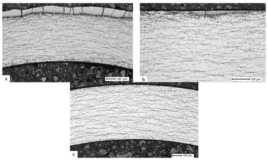
Figure 1.
E110 zirconium alloy transverse metallographic section after hydrogenation at the temperatures 350 °C (a), 380 °C (b), and 420 °C (c), and the pressure 2 atm. up to hydrogen concentration 0.1 wt.%.
It has been established that the hydrogenation temperature effects hydride rim formation. Rim formation takes place at the temperature 320 °C, while, at the temperature 380 °C, the hydride rim is practically not observed, and at the temperature 420 °C, the hydride rim is not present. This is explained by the following: hydride rim formation takes place in the cases where the hydrogen solubility in the thin layer of zirconium alloy during hydrogenation is exceeded and the hydrogen absorption rate is higher than the hydrogen diffusion rate in relation to the observed thin layer. After hydrides have been formed in the thin layer, hydrogen diffusion penetrates through this layer further to the alloy volume, where hydrides are also being formed.
Table 1 represents the results of the X-ray diffraction analysis of the E110 zirconium alloy cladding tube samples after hydrogenation under different temperatures.

Table 1.
The results of X-ray diffraction analysis of the samples.
The results of the X-ray diffraction analysis reveal that, with a hydrogenation temperature increase, there is a decrease in the hydride phase volume in zirconium alloy, which is in good agreement with the results of the metallographic examination. A hydrogenation temperature increase leads to hydride formation in the material bulk and, correspondingly, the inclusion volume of the hydrides in the near-surface layers decreases.
3.2. The Effect of Hydrogen Concentration on the Hydride Rim Thickness
Below, Figure 2 presents the results of the metallographic examination using the optical microscope performed for the hydrogenated samples of the E110 alloy cladding tubes at the temperature 350 °C, the pressure in the chamber 2 atm., and up to concentrations 0.1–0.25–0.4 wt.%.
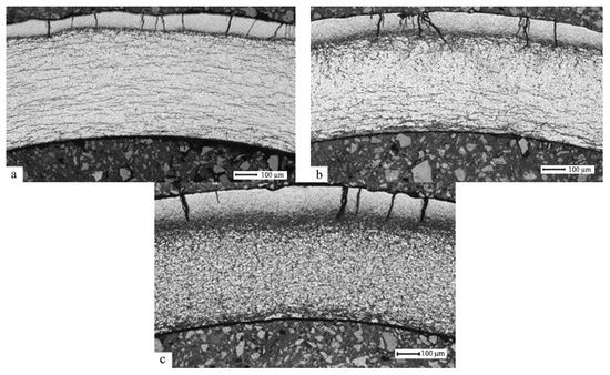
Figure 2.
E110 zirconium alloy transverse metallographic section after hydrogenation at the temperature 350 °C and the pressure 2 atm. up to concentrations 0.1 (a) – 0.25 (b) – 0.4 (c) wt.%.
It has been established that hydride rim thickness depends on hydrogen concentration. An increase in concentration from 0.1 wt.% to 0.4 wt.% leads to an increase in the hydride rim thickness from 90 µm to 180 µm. Table 2 represents the results of the X-ray diffraction analysis of the samples of the E110 zirconium alloy cladding tubes after hydrogenation to different concentrations.
Table 2.
The results of X-ray diffraction analysis of the samples.
The results of the X-ray diffraction analysis reveal that, with a hydrogen concentration increase at the same hydrogenation temperature, the increase of the hydride phase volume in the zirconium alloy takes place, which is in good agreement with the results of the metallographic examination. The hydrogen concentration increases at the same temperature of hydrogenation, which leads to a hydride rim thickness increase [25].
Thus, gas-phase hydrogenation of the E110 zirconium alloy cladding tubes in the delivery condition under the constant pressure of 2 atm. within the temperature range (400–550) °C and subsequent slow cooling leads to the formation of hydrides formed in the material bulk. Hydrogenation at the temperatures that are lower than the threshold temperature (400 ± 20) °C is accompanied by hydride rim formation in the cladding tubes; the hydride rim thickness is within the range (90–180) µm, with hydrogen concentrations within the range (0.1–0.4 wt.%).
3.3. The Effect of the Gas-Phase Hydrogenation Temperature on the Value of the Threshold Temperature of Hydride Rim Formation in E110 Zirconium Alloy Subjected to Ion-Beam Cleaning and Nickel Coating
Below, Figure 3 presents the results of the metallographic examination using the optical microscope performed for the hydrogenated samples of the E110 alloy cladding tubes subjected to ion-beam cleaning and nickel coating (the method of ion-beam cleaning and nickel coating is described in [23]) at the temperatures 350 °C, 380 °C, 420 °C, 500 °C, and 550 °C. The pressure in the chamber is 2 atm. and up to the concentration of 0.1 wt.%.
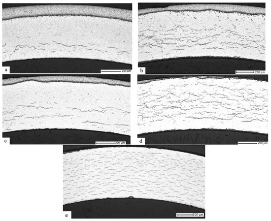
Figure 3.
E110 zirconium alloy transverse metallographic section subjected to ion-beam cleaning and nickel coating after hydrogenation at the temperatures 350 °C (a), 400 °C (b), 450 °C (c), 500 °C (d), and 550 °C (e), and the pressure 2 atm. up to hydrogen concentration 0.1 wt.%.
It has been established that hydride rim formation in the E110 zirconium alloy subjected to ion-beam cleaning and nickel coating takes place at the temperatures 350 °C (a), 400 °C (b), and 450 °C (c). At the temperature 500 °C, the hydride rim is practically not observed, and at the temperature 550 °C, the gradient is not present.
Thus, argon ion-beam cleaning (under the voltage 2000 V, the power 1000 W, the current 0.5 A, and the pressure 6 × 10⁻² Pa during 5 min) and subsequent nickel coating using the magnetron sputtering method (under the voltage 500 V, the power 2000 W, the current 3 A, and the pressure 1 × 10⁻¹ Pa) with the thickness ~1 µm on the E110 zirconium alloy cladding tubes leads to an increase in the threshold temperature value of hydride rim formation in ~100 °C, which is related to the significant increase of the hydrogen absorption rate. It is worth noting that the observed features of the hydride distribution behavior throughout the zirconium cladding volume correlate to the data available from the results of the analysis of hydride distribution in the cladding after the operation [26].
3.4. Studies of the Properties of the Hydride Rim Formed during Gas-Phase Hydrogenation in E110 Zirconium Alloy
Below, Figure 4 presents the results of the studies of element distribution throughout the thickness of the E110 zirconium alloy with the formed hydride rim of the thickness 110 µm. The element signal strength is presented in the relative unit values, since, to be able to determine hydrogen concentration using this method, it is necessary to prepare the reference samples of hydrogen and oxygen in zirconium alloys. However, based on the correlation of the signals of different elements, it is possible to judge the correlation of these elements’ quantities in the samples.
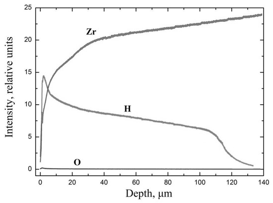
Figure 4.
Distribution of elements through the thickness of E110 zirconium alloy with the formed hydride rim of the thickness 110 µm at the temperature 350 °C.
As the studies have revealed, there is a layer up to ~110 µm with high hydrogen concentration in the sample. At that, with the depth growth, the zirconium signal strength increases, which evidences the decrease of hydrogen concentration and the presence of the gradient of hydrogen distribution right in the hydride layer. This can be explained by the following: hydride formation takes place immediately after hydrogen penetration in a thin layer of zirconium. Further penetration of hydrogen leads to an increase in the thickness of the hydride layer directly in the process of hydrogenation. This situation is observed at a high hydrogen penetration rate and a low diffusion rate. In our experiment, this was achieved by cleaning the surface, high pressure, and low temperature. Thus, if the rate of the outflow of hydrogen from a thin surface layer of zirconium is greater than the rate of the penetration of hydrogen into the material, then the hydride rim will not form during hydrogenation. In our experiment, this was achieved by increasing the temperature (Figure 1c and Figure 3e). In the case of the formation of the hydride rim directly during hydrogenation, the hydrogen distribution gradient over the depth of the layer is observed due to the lower diffusion rate of hydrogen in zirconium hydride compared to pure zirconium.
This fact has been confirmed by the studies of the sample’s nanohardness distribution in the transverse metallographic section. The measurement results for the sample’s microhardness before and after hydrogenation are presented in Figure 5. The hydride layer is characterized by high hardness in comparison to the material volume.
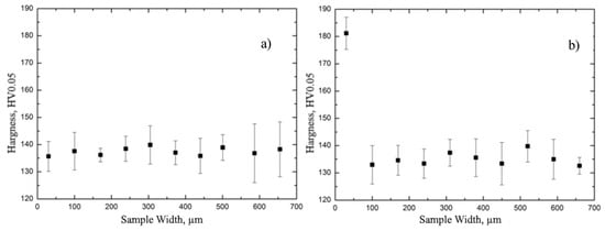
Figure 5.
The measurement results of E110 zirconium alloy microhardness before (a) and after (b) hydrogenation, with the hydride rim formed with the thickness of 110 µm.
The volume of the zirconium alloy is characterized by the uniform distribution of hardness in the thickness. After hydrogenation at the temperature lower than the threshold temperature, the hardness significantly increases up to the depth of 100 µm, which can be explained by hydride rim formation. The results of the studies of the sample’s nanohardness distribution in the transverse metallographic section are presented in Figure 6.
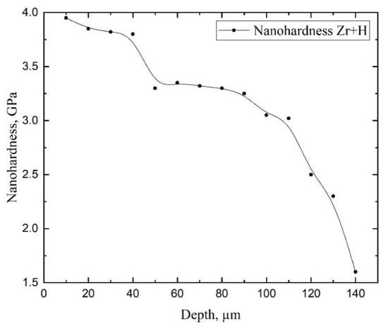
Figure 6.
The measurement results of nanohardness of E110 zirconium alloy with hydride rim 110 µm.
As the studies have revealed, hardness in the hydride rim decreases from the outer layer into the material volume, which evidences the presence of the hydrogen concentration gradient in the hydride rim, which, in turn, confirms the suggested mechanism of hydride rim formation. In the hydride rim, in regions close to the surface, hydrogen concentration is very high, and the formation of epsilon hydrides takes place. By approaching towards the bulk, hydrogen concentration decreases, and at some depths, it is not enough for epsilon hydride formation. Hence, the delta hydrides form. The observed variation in hardness is due to this phase change: i.e., close to the surface, we are measuring the hardness of epsilon hydrides, but close to the bulk, we are measuring the hardness of delta hydrides.
Hydride rim formation takes place in the cases when hydrogen solubility is exceeded in the thin layer of zirconium alloy during hydrogenation and when the hydrogen absorption rate exceeds the hydrogen diffusion rate of the thin layer under study. After hydride formation in the thin layer, hydrogen diffusion occurs through this layer further into the alloy volume, where hydride formation also takes place.
4. Summary
The present research is focused on the studies of the behavior of hydride rim formation in the E110 zirconium alloy cladding tubes during gas-phase hydrogenation. The problem of hydrogen penetration and accumulation and subsequent hydride formation in the volume of zirconium cladding tubes of the PWR-type reactors remains relevant. The formation of fragile hydrides in the zirconium matrix leads, firstly, to significant changes in mechanical properties, and secondly, can cause through-the-thickness damage of cladding in compliance with the mechanism of delayed hydride cracking. The degree of the hydrides’ negative effect is for the most part determined by the specifics of their distribution and orientation. The problem of hydride rim formation is relevantly new and insufficiently studied. Due to this, the studies of the behavior of hydride rim formation in Russian zirconium alloy are of importance and necessary to be able to prognose the cladding tube behavior during hydride rim formation.
The results obtained during this research allow us to make the following conclusions:
- It has been established that, during gas-phase hydrogenation of the E110 zirconium alloy, the cladding tubes in the delivery condition under the constant pressure of 2 atm., within the temperature range (400–550) °C, up to hydrogen concentrations (0.1–1) wt.%, and subsequent slow cooling is where the formation of hydrides in the bulk of the material takes place.
- It has been demonstrated that in the E110 zirconium alloy cladding tubes, the formation of hydride rims of different thicknesses is achieved due to hydrogenation at the temperatures lower than the threshold temperature (400 ± 20) °C up to different hydrogen concentrations. The observed specifics of hydride distribution in the volume of zirconium cladding coincide with the data available as a result of the analysis of hydride distribution in the cladding after the operation.
- It has been experimentally proven that the hydride rim formed in the E110 zirconium alloy cladding tubes is characterized by the nonuniform distribution of hardness and hydrogen concentration through the thickness.
- It has been experimentally proven that E110 zirconium alloy surface modification, using the method of argon ion-beam cleaning (under the voltage 2000 V, the power 1000 W, the current 0.5 A, and the pressure 6 ×·10−2 Pa during 5 min) and subsequent nickel coating using the method of magnetron sputtering (under the voltage 500 V, the power 2000 W, the current 3 A, and the pressure 1 ×·10−1 Pa) with the thickness of ~1 µm on the E110 zirconium alloy cladding tubes, leads to the increase of the threshold temperature value of hydride rim formation in 100 °C, which is related to the significant increase of the hydrogen absorption rate.
Thus, the conducted series of studies and the developed methods allow a detailed investigation into the processes of hydrogen embrittlement and the delayed hydride cracking of zirconium alloys to enable the validation of the project criteria and ensure the operating capacity of pressured water reactors’ cladding tubes.
Author Contributions
V.K. made the organization of the workflow and preparation of the article, M.S. performed XRD tests, I.S. (Ivan Sakvin) conducted experiments on hydrogenation, I.S. (Inga Slesarenko) and A.L. made an analysis of the results. All authors have read and agreed to the published version of the manuscript.
Funding
The research was funded by the Governmental program “Science”, research project No. FSWW-2020-0017.
Acknowledgments
This work was carried out within the framework of the Competitiveness Enhancement Program of National Research Tomsk Polytechnic University.
Conflicts of Interest
The authors declare no conflict of interest.
References
- Azevedo, C.R.F. Selection of Fuel Cladding Material for Nuclear Fission Reactors. Eng. Fail. Anal. 2011, 18, 1943–1962. [Google Scholar] [CrossRef]
- Hallstadius, L.; Johnson, S.; Lahoda, E. Cladding fo high performance fuel. Prog. Nucl. Energy 2012, 57, 71–76. [Google Scholar] [CrossRef]
- Primakov, N.G.; Rudenko, V.A.; Kazarnikov, V.V.; Bespalov, A.G. Nonuniform Swelling and Hydrogen Redistribution in Zirconium Hydride under Neutron Irradiation. Int. J. Hydrog. Energy 1999, 24, 805–811. [Google Scholar] [CrossRef]
- Ribeiro, R.M.; Woyames, C.B.; de Almeida, L.H.; dos Santos, D.S. Effect of Microstructure and Addition of Alloying Elements on Hydriding Kinetics of Zr–Nb-based Alloys. Int. J. Hydrog. Energy 2015, 40, 17118–17127. [Google Scholar] [CrossRef]
- Kazarnikov, V.V.; Primakov, N.G.; Rudenko, V.A. Effect of neutron irradiation on the microstructure of zirconium hydride. Int. J. Hydrog. Energy 1997, 22, 169–173. [Google Scholar] [CrossRef]
- Zhao, C.; Song, X.; Yang, Y.; Zhang, B. Hydrogen Absorption Cracking of Zirconium Alloy in the Application of Nuclear Industry. Int. J. Hydrog. Energy 2013, 38, 10903–10911. [Google Scholar] [CrossRef]
- Ivanova, S.V. Hydrogen Effected Defects Evolution in Zirconium Items of Light-water Reactors. Int. J. Hydrog. Energy 2006, 31, 295–300. [Google Scholar] [CrossRef]
- Tang, R.; Yang, X. Dissolution and Precipitation Behaviors of Hydrides in N18, Zry-4 and M5 alloys. Int. J. Hydrog. Energy 2009, 34, 7269–7274. [Google Scholar] [CrossRef]
- Zielinski, A.; Sobieszczyk, S. Hydrogen-enhanced Degradation and Oxide Effects in Zirconium Alloys for Nuclear Applications. Int. J. Hydrog. Energy 2011, 36, 8619–8629. [Google Scholar] [CrossRef]
- Chen, L.; Wang, X.; Gong, W.; Zhang, H. Effect of Yttrium Addition on Microstructure and Orientation of Hydride Precipitation in Zr-1Nb Alloy. Int. J. Hydrog. Energy 2014, 39, 21116–21126. [Google Scholar] [CrossRef]
- Kearns, J.J. Terminal Solubility and Partitioning of Hydrogen in the Alpha–phase of Zirconium. Zircaloy-2 and Zircaloy-4. J. Nucl. Mater. 1967, 22, 292–303. [Google Scholar] [CrossRef]
- Nagase, F. Hydride Behavior in Zircaloy Cladding Tube during High-temperature Transients. J. Nucl. Mater. 2011, 415, 117–122. [Google Scholar] [CrossRef]
- Daum, R.S. The Influence of a Hydrided layer on the Fracture of Zircaloy-4 cladding Tubes. In Hydrogen Effects on Material Behavior and Corrosion Deformation Interactions; Moody, N.R., Thompson, A.W., Was, G.S., Jones, R.H., Eds.; The Minerals and Materials Society, Argonne National Lab.: Lemont, IL, USA, 2003; pp. 249–259. [Google Scholar]
- Motta, A.T.; Chen, L.Q. Hydride Formation in Zirconium Alloys. J. Miner. Met. Mater. Soc. 2012, 64, 1403–1408. [Google Scholar] [CrossRef]
- Nagase, F.; Fuketa, T. Investigation of Hydride Rim Effect on Failure of Zircaloy-4 Cladding with Tube Burst Test. J. Nucl. Sci. Technol. 2005, 42, 58–65. [Google Scholar] [CrossRef]
- Terrani, K.A.; Balooch, M.; Wongsawaeng, D.; Jaiyen, S.; Olander, D.R. The Kinetics of Hydrogen Desorption from and Adsorption on Zirconium Hydride. J. Nucl. Mater. 2010, 397, 61–68. [Google Scholar] [CrossRef]
- Suman, S.; Khan, M.K.; Pathak, M.; Singh, R.N. 3D Simulation of Hydride-assisted Crack Propagation in Zircaloy-4 Using XFEM. Int. J. Hydrog. Energy 2017, 42, 18668–18673. [Google Scholar] [CrossRef]
- Hanson, B.; Shimskey, R.; Lavender, C.; MacFarlan, P.; Eslinger, P. Hydride Rim Formation in Unirradiated Zircaloy. Available online: http://www.energy.gov/sites/prod/files/2013/08/f2/HydrideRimFormationZircaloy.pdf (accessed on 30 December 2019).
- Shimskey, R.; Hanson, B.; MacFarlan, P. Optimization of Hydride Rim Formation in Unirradiated Zr-4 Cladding. Available online: http://www.pnnl.gov/main/publications/external/technical_reports/PNNL-22835.pdf (accessed on 30 December 2019).
- Pushilina, N.S.; Lider, A.M.; Kudiiarov, V.N.; Chernov, I.P.; Ivanova, S.V. Hydrogen effect on zirconium alloy surface treated by pulsed electron beam. J. Nucl. Mater. 2015, 456, 311–315. [Google Scholar] [CrossRef]
- Motta, A.T.; Capulongo, L.; Chen, L.-Q.; Cinbiz, M.; Daymond, M.; Koss, D.A.; Lacroix, E.; Pastore, G.; Simin, P.-C.; Tonks, M.R.; et al. Hydrogen in Zirconium Alloys: A review. J. Nucl. Mater. 2019, 518, 440–460. [Google Scholar] [CrossRef]
- Pushilina, N.S.; Kudiiarov, V.N.; Laptev, R.S.; Lider, A.M.; Teresov, A.D.R. Microstructure Changes in Zr–1Nb Alloy after Pulsed Electron Beam Surface Modification and Hydrogenation. Surf. Coat. Technol. 2015, 284, 63–68. [Google Scholar] [CrossRef]
- Kudiiarov, V.N.; Kashkarov, E.B.; Syrtanov, M.S.; Lider, A.M. Hydrogen Sorption by Ni-coated Titanium alloy VT1-0. Int. J. Hydrog. Energy 2017, 42, 10604–10610. [Google Scholar] [CrossRef]
- Kido, T.; Sugano, M. Development of a Method to Charge Hydrogen into Zirconium Alloys. Nippon Genshiryoku Gakkai Wabun Ronbunshi 2002, 1, 469–471. [Google Scholar] [CrossRef][Green Version]
- Zuzek, E.; Abriata, J.P.; San-Martin, A.; Manchester, F.D. The H-Zr (hydrogen-zirconium) System. Bull. Alloy Phase Diagr. 1990, 11, 385–395. [Google Scholar] [CrossRef]
- Sindelar, R.L.; Louthan, M.R.; Hanson, B.D. White Paper Summary of 2nd ASTM International Workshop on Hydrides in Zirconium Alloy Cladding. Available online: http://sti.srs.gov/fulltext/FCRD-UFD-2015-000533_SRNL-STI-2015-00256.pdf (accessed on 12 February 2020).


© 2020 by the authors. Licensee MDPI, Basel, Switzerland. This article is an open access article distributed under the terms and conditions of the Creative Commons Attribution (CC BY) license (http://creativecommons.org/licenses/by/4.0/).