Article

Processing by Additive Manufacturing Based on Plasma Transferred Arc of Hastelloy in Air and Argon Atmosphere

by
Eva M. Perez-Soriano
1,
Enrique Ariza
2,
Cristina Arevalo
1,
Isabel Montealegre-Melendez
1,*,
Michael Kitzmantel
2 and
Erich Neubauer
2
1
Escuela Politécnica Superior, Universidad de Sevilla, 41011 Sevilla, Spain
2
RHP Technology GmbH, 2444 Seibersdorf, Austria
*
Author to whom correspondence should be addressed.
Metals 2020, 10(2), 200; https://doi.org/10.3390/met10020200
Submission received: 30 December 2019 / Revised: 27 January 2020 / Accepted: 28 January 2020 / Published: 30 January 2020
(This article belongs to the Special Issue Additive Manufacturing of Metals)

Abstract

:
This research was carried out to determinate the effect of the atmosphere processing conditions (air and argon) and two specific thermal treatments, on the properties of specimens made from the nickel-based alloy Hastelloy C-22 by plasma transferred arc (PTA). Firstly, the additive manufacturing parameters were optimized. Following, two walls were manufactured in air and argon respectively. Afterwards, a determinate number of specimens were cut out and evaluated. Regarding the comparison performed with the extracted specimens from both walls, three specimens of each wall were studied as-built samples. Furthermore, a commonly used heat treatment in Hastelloy, with two different cooling methods, was selected to carry out additional comparisons. In this respect, six additional specimens of each wall were selected to be heat treated to a temperature of 1120 °C for 20 min. After the heat treatment, three of them were cooled down by rapid air cooling (RAC), while the other three were cooled down by water quenching (WQ). In order to study the influence degree of the processing conditions, and how the thermal treatments could modify the final properties of the produced specimens, a detailed characterization was performed. X-ray diffraction and microstructural analyses revealed the phases-presence and the apparition of precipitates, varying the thermal treatment. Moreover, the results obtained after measuring mechanical and tribological properties showed slight changes caused by the variation of the processing atmosphere. The yield strength of the extracted specimens from the two walls achieved values closer to the standards ones in air 332.32 MPa (±21.36 MPa) and in argon 338.14 MPa (±9 MPa), both without thermal treatment. However, the effect of the cooling rate resulted as less beneficial, as expected, reducing the deformation properties of the specimens below 11%, independently of the air or argon manufacturing atmosphere and the cooling rate procedure.

Graphical Abstract

1. Introduction

In recent years, additive manufacturing technologies have become valued processes based on their competitive and comparative advantages in the production of specimens with complex geometries. Regarding the technique developments, one classification could then be done dividing into two big groups in light of the way the material is provided: Powder bed techniques or blown-powder/wire-feed techniques [1,2,3,4,5,6,7].
The technology of plasma transferred arc (PTA) is considered one of the most interesting additive techniques to process specimens through layer depositions [8,9,10,11] by blown powder. When the wire is employed, the technique could be considered as one of the wire arc additive manufacturing (WAAM) processes, in addition to tungsten inert gas/metal inert gas (TIG/MIG) [12]. The PTA is included in the recently named group 3D Plasma Metal Deposition (3DPMD) that belongs to the category of directed energy deposition processes [13,14,15]. This manufacturing process permits us to carry out the fabrication of specimens with larger dimensions than specimens produced by powder bed techniques. Furthermore, the production rate might be higher due to the employment of a higher feed rate in comparison to other additive techniques [16,17].
In order to research the possibilities of developing materials with interesting properties, this study was proposed. The flexibility of the employed technique allowed the realization of a detailed investigation of possible changes in the final specimen’s properties as consequence of variation in the setup parameters. The selected material was Hastelloy C-22. This alloy presents excellent corrosion behavior as well as mechanical properties, being commonly employed in the industrial sectors [18,19,20,21,22,23]: Chemical, petrochemical, aerospace, etc.
The main goal of this research was the production of Hastelloy C-22 walls with good mechanical properties by PTA. In pursuing this goal, the aim of this study was threefold: (1) The manufacturing of walls made from Hastelloy with large dimensions by the optimization of processing parameters; (2) the determination of influence degree in the specimens of the manufacturing atmosphere, in air or argon conditions; and (3) the evaluation of thermal treatments on the final behavior of specimens. Therefore, a wall was fabricated in air conditions firstly, and a second wall was built in argon atmosphere subsequently. Thereafter, from the two walls, determined samples were extracted from marked positions to compare their final properties. Moreover, two thermal treatments were defined to evaluate if the specimens would suffer variation in their properties caused by their cooling rate.

2. Materials and Methods

The starting material employed was powder from Hastelloy C-22, supplied by Atomising Systems Limited (Sheffield, UK). This powder was produced by the conventional method of powder manufacturing known as plasma-atomization process. In Figure 1, the spherical morphology of the Hastelloy particles can be appreciated. Furthermore, the chemical composition of the manufactured powder was compared to the standard one; both are listed in Table 1. In the granulometry given by the manufacturer, d50 (average) was 82.74 µm, and d10 and d90 were 57.39 µm and 125.14 µm, respectively.
After the powder characterization, the production of the specimens was developed. In this research, the additive manufacturing equipment used for this research was based on PTA technology, self-made, and adapted (RHP-Technology GmbH, Seibersdorf, Austria). In the torch, the plasma was generated. Then, the feeding materials were melted with the plasma energy (Figure 2).
As novelty in this research, an argon atmosphere was employed, in addition to an air conventional atmosphere. When using an argon atmosphere, the specimens were built inside a designed argon box. For ensuring the environmental conditions, an oxygen sensor (Oxy 3. Orbitec GmbH, Seligenstadt, Germany) was placed near the torch [24].
The torch had an internal cooling circuit where water ran, preventing its melting due to the plasma. The distance between the torch and the substrate or specimen during the fabrication was 10 mm. An argon plasma was induced by introducing the gas between the electrode and the copper cylinder (pilot gas, 1.5 L/min), applying a potential of 20 V. The pilot flame was employed to start the plasma arc between the electrode and the substrate connected to ground. Different electric currents could be applied to increase or decrease the intensity of the plasma arc energy.
At the same time, building in air atmosphere, there was another gas that acted as a shield (shielding gas, 15 L/min) preventing the seam from oxidizing during the process. It was applied by coupling an external copper cylinder to the torch. Several gases could be inserted as shielding gases, as argon pure or mixed with a 5 vol% CO2 gas, depending on the material to be processed, and the properties to be reached. In this investigation, pure argon (99.99% purity, Air Liquide, Paris, France) was employed as shielding gas in the manufacturing of all the specimens.
The material was fed as powder to the plasma jet by aligned holes. For a better powder flowing through the ducts, it was injected with a pressurized gas (powder gas, 1.5 L/min), argon.
This additive manufacturing equipment could build large size components thanks to the torch fixed to an XYZ mechanical, which allowed the torch to move through the working table. This working table was made from aluminum profiles, cooled to ease the heat transfer through the system.
Firstly, a flow test was performed to check if the powder size and shape were optimal for the process. Values in g/min after using different engine units (U) of the rotating metering powder feeder were obtained during the flowability test (Figure 3). A clear linear trend was obtained as the value of motor unit’s increase. This means that the powder had a good flow through the ducts of the system and there were no clogging problems.
After checking the flowability of the powders, a preliminary bead on a plate welding test was conducted with different parameters (see Table 2), to properly select the more efficient ones and to produce the best quality seam for a subsequent application to the final sample structure. Several parameters’ combinations were tested in order to meet a range of processing conditions. By varying the most significant processing parameters (current 120–250 A, speed 100–400 mm/min, material feed rate 11–43.5 g/min), different single seams were welded on a steel AISI 1015 (Figure 4). The dimensions of this substrate were 200 mm × 300 mm × 10 mm. The surface was previously cleaned by brushing.
There were no initial geometrical specifications (seam width and height) predefined in this work. The final height resulted from the layer deposition, and the seam width was the obtained under the fabrication parameters.
By visual inspection, the parameters of the seams with better geometrical and surface quality were selected (6, 7, and 10 from Figure 4). Then, oscillation bead on plate welding tests were performed with these conditions (Figure 5). The oscillation movement helped to improve the quality of the different parts because the torch stayed longer on top of the hot spot after the melting pool. The oscillation parameters were: (1) The amplitude, 7.5 mm and (2) the overlapping, 2.5 mm. The oscillation amplitude resulted in 15 mm for the walls width. The shielding gas protected more during the very beginning of the cooling of the pool, reducing the oxidation due to high temperature. Considering the most promising parameters, seam number 14 from Figure 5, the constructions of both walls were conducted in air and argon. This sample was the candidate selected based on a visual checking of the first manufactured specimens, thus there were neither cracks nor pores.
Obviously, the height of the resulting wall was set considering the height of each layer deposition. Setting the parameters listed in Table 3, the walls of dimensions 120 mm × 40 mm × 15 mm were manufactured. To reach this height of 40 mm, 16 layers were necessary, as can be appreciated in Table 3 and Figure 6. With the purpose of obtaining a proper comparison in the study of the effect of the manufacturing atmosphere on the material properties, the similar parameters, strategy, and the number of layers were used to build both walls, in air and argon atmospheres.
Next, the extraction of the specimens was conducted following a determinate distribution plan and marks of the location of the cut specimens from each wall. The cutting machine employed was an electrical discharge machine Mitsubishi FX-20 (Mitsubishi, Ratingen, Germany). The geometry of the tensile samples is shown in Figure 7, as well as the sample disposition on the wall. Three sets of samples were extracted.
The extracted specimens were studied under determined conditions: (1) As built, (2) after thermal treatment 1 (TT1), and (3) after thermal treatment 2 (TT2). Therefore, the heat treatment parameters were previously set up according to recent bibliography [25]. The cooling stage was the main difference between them. The two sets of samples were heat-treated at 1120 °C for 20 min in a high vacuum furnace under an argon atmosphere. On the one hand, the set named TT1 suffered a cooling down by rapid air cooling (RAC = TT1). On the other hand, the remaining treated set (named TT2) was cooled down by water quenching (WQ = TT2) after the heat treatment (Figure 8).
The study of the specimens was conducted through a detailed characterization. The microstructural study was performed by scanning electron microscopy (SEM) using a TENEO 6460LV microscope (FEI Teneo, Hillsboro, OR, USA), equipped with an energy dispersive X-ray spectrometry (EDS) system to carry out the phase analysis. X-ray diffraction (XRD) analysis was performed by a Bruker D8 Advance A25 (Bruker, Billerica, MA, USA) with Cu-Kα radiation. In a tester model, Struers-Duramin A300 (Struers, Ballerup, Denmark), the measurement of the mechanical properties was performed to ascertain the Vickers hardness (HV2). Room-temperature tensile tests were performed on a universal testing machine Instron 5505 (Instron, Norwood, MA, USA) with a strain rate of 0.5 mm·min−1. Concluding the characterization, the tribological behavior of the samples was determined by a ball-on-disc tribometer (Microtest MT/30/NI, Madrid, Spain) using aluminum balls (6 mm in diameter) with a sliding speed of 200 rpm and a normal load of 5 N on the ball during 15 min on a circular path of 2 mm in radius. The surface morphology was studied by optical microscopy (OM) with a Leica Zeiss DMV6 (Leica Microsystems, Heerbrugg, Switzerland).

3. Results

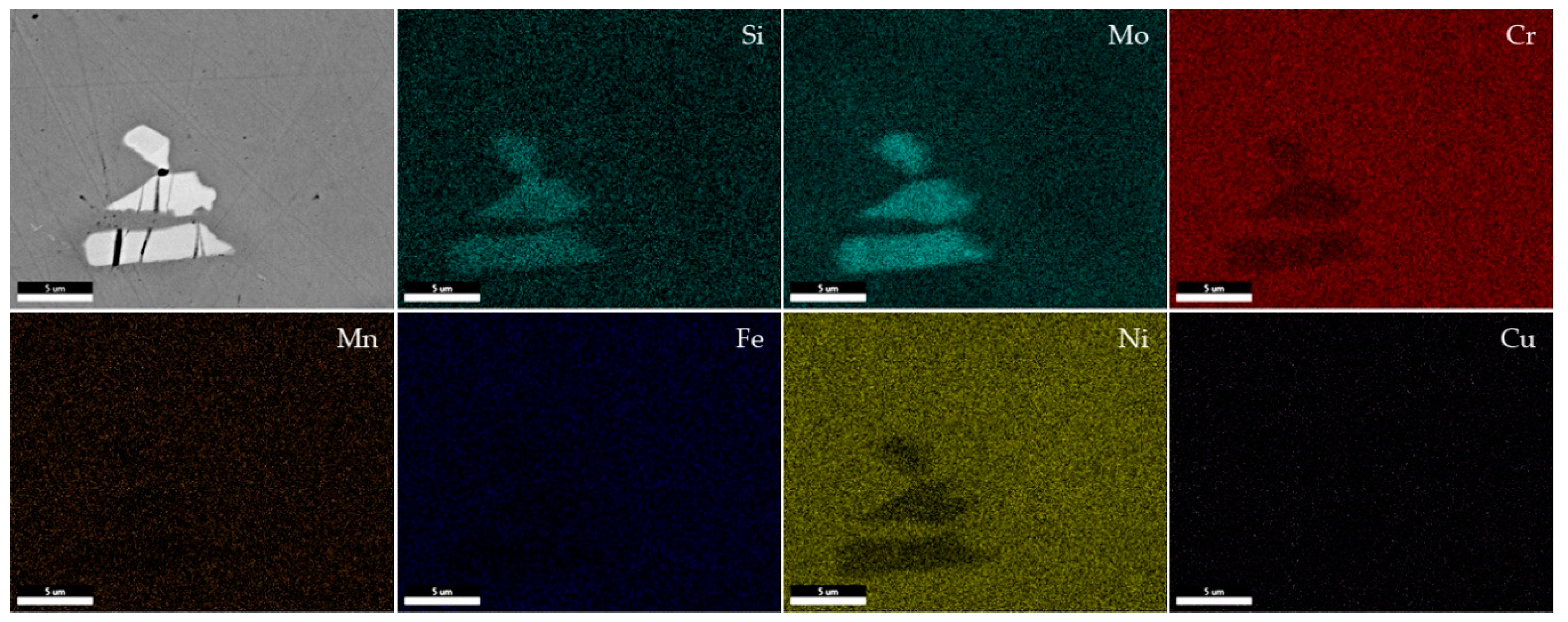
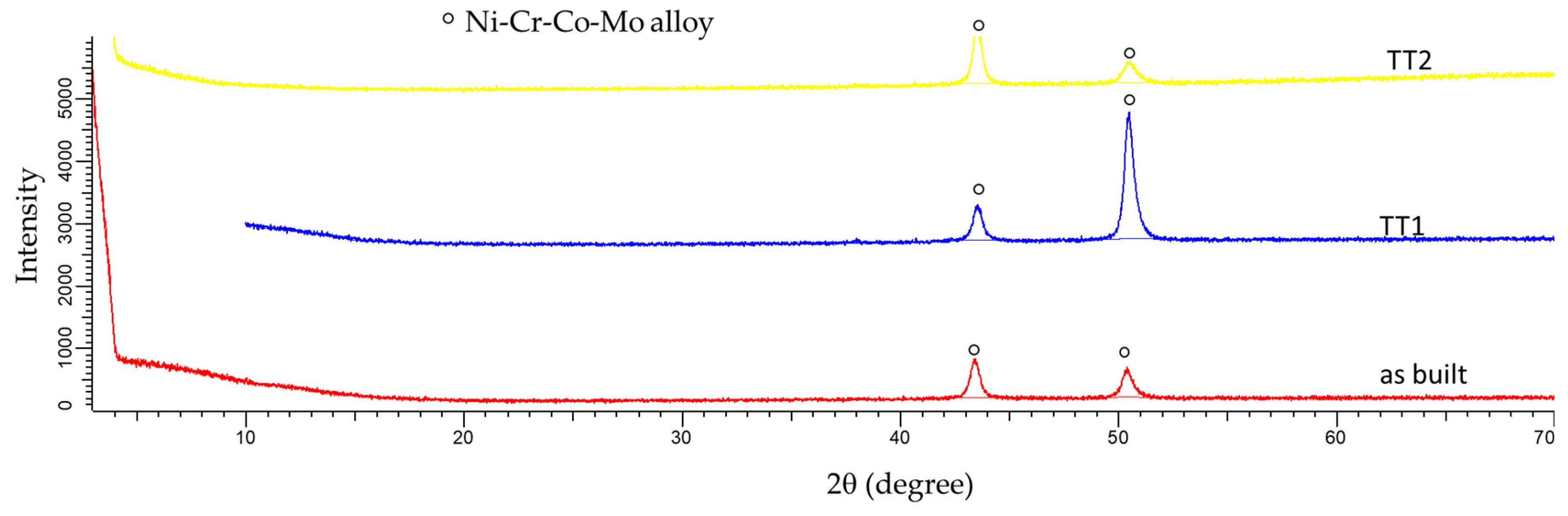
3.1. Microstructural Study and XRD Analysis

The microstructural study revealed, in general, the apparition of precipitates that showed a distribution mainly oriented. Then, two typologies of phases were clearly differenced, a darker area named “matrix”, and plenty of light grey precipitates. In Figure 9, the SEM images showed such precipitates, as well as their special orientation in the microstructure of a specimen fabricated under air and argon conditions during the PTA process without thermal treatment (named “as-built”), and placed at the position 1.2 (according to Figure 7) in both Hastelloy C-22 walls.
As can be seen in Figure 9a,c and Figure 10, at low magnifications (100×) the grain distribution could be clearly identified, regardless of the thermal treatment. Therefore, their origin and distribution could be attributed to possible segregation phenomena during the additive process. Residual porosity could be observed in the specimens, even after the heat treatments.
Subsequent test by EDS analysis confirmed the compositional differences between the darker regions (matrix) and the light grey precipitates, observed in Figure 9. The representative spots checked, in addition to the results of the EDS analysis, are summarized in Figure 11 and Table 4. The elements analysis in light grey spots resulted in regions rich mainly in Mo, and in which the percentage in weight of Cr and Ni elements were lower than in the area considered as the matrix in the Hastelloy C-22. That suggested a possible diffusion of the Mo atoms, mainly during the layer depositions, as well as decrement of other characteristic elements of the Hastelloy C-22, as Ni and Cr. The mapping test (Figure 12) confirmed the elements’ compositional variations occurred in the alloy, caused by the manufacturing process. Similar results were obtained in analysis carried out in other specimens processed in argon and thermal treated.
The XRD analyses were performed, and the patterns of specimens produced under air are shown in Figure 13 and the ones manufactured in argon atmosphere are illustrated in Figure 14. The pattern of specimens without thermal treatment processing in air showed the highest peaks in comparison with the observed peaks in the pattern of the rest of the specimens under air or argon independently. This result suggested that the intensity of these peaks was related to the high crystallinity that this specimen could present. On the contrary, the alloy peaks belonging to the specimen processed under argon without any thermal treatment showed low intensity; note, in that regards, the processing conditions modified the characteristics on the crystallinity of the specimens. The pattern of specimens treated by cool down by water quenching (WQ = TT2) after the heat treatment showed almost the same tendency of the alloy peaks, independently of the processing conditions.
As it can easily appreciate, there were significant differences in the patterns of specimens whose thermal treatment finalized by rapid air cooling (TT1). This cooling process presented the lowest cooling rate, promoting in this stage singular variations in the crystallinity and phases presented in the specimens. Hence, in the framework of the thermal treatments, significant variations were found in the patterns of specimens where the crystallinity could be affected by the circumstances related to the cooling rate, independently of the air or argon fabrication conditions. Possible phases could be forming since peaks of these phases as FeNi and carbides could be matched to the main alloy peak. However, they were probably overlapped under the alloy peak. For that reason, the mentioned peaks were not marked in Figure 13 and Figure 14.

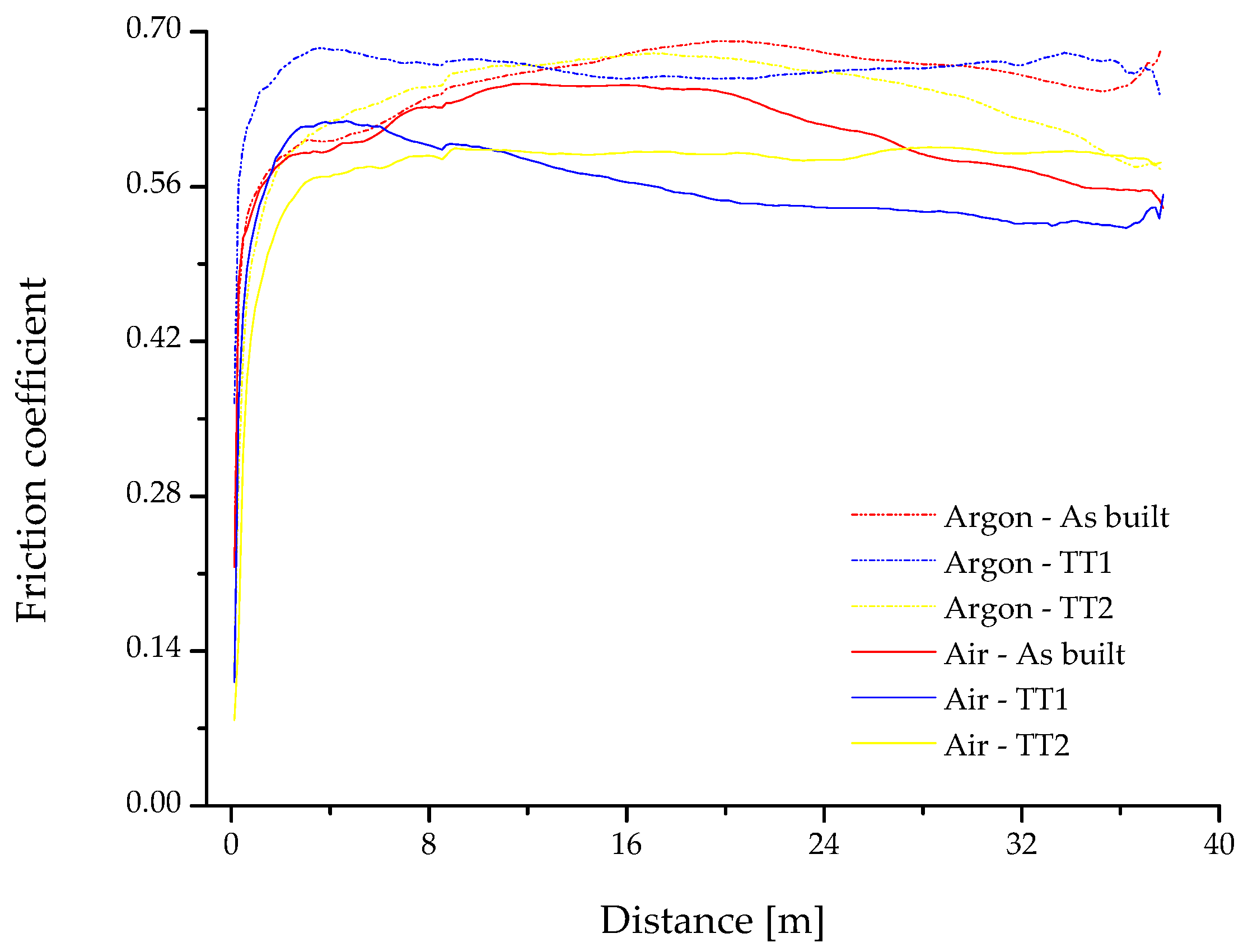
3.2. Mechanical Properties and Wear Behavior

In this section, the mechanical properties obtained by tensile tests were studied and evaluated. The values of the most representative mechanical properties are summarized in Table 5 and Table 6, being Young’s modulus (E), yield strength (YS), ultimate tensile strength (UTS), and deformation. Three specimens were tested for each category, which means three specimens without treatment, three suffered a cooling down by rapid air cooling (TT1), and three after treatment by cool down by water quenching (TT2). When the empirical values of mechanical properties were compared to the theoretical ones, slight differences were observed [26]. The Hastelloy C-22 walls produced by the PTA technology, in average, (Table 5 and Table 6) did not reach the mechanical properties that indicate the standard reference, the elongation properties, in particular, independently of the processing conditions and the thermal treatment [27]. This behavior is characteristic of the additive manufacturing process itself. While the YS values were closer to the minimum reference values (310 MPa) and UTS values were slightly lower than the reference ones (690 MPa), the elongation results were very low, not achieving even one-third or one-fourth of the standard value (reference value 45% of elongation). These results were similar with other ones obtained using additive manufacturing techniques [28]. Moreover, after performing the different thermal treatments (TT1 and TT2), the mechanical properties did not undergo some significant improvements. Although UTS properties in specimens fabricated in air and after TT1 and TT2 slightly improved on average, 660 MPa and 644 MPa, respectively, the elongation receded from the reference visibly below 11% and 9.2% in each case. Regarding the cooling rates referred to TT1 and TT2, the results suggested that the low cooling rate (TT1 = RAC) improved more the UTS than using a high cooling rate (TT2 = WQ) (see Table 5). In specimens processed in argon conditions, the mechanical properties showed almost the same trend, affecting the highest cooling rate (TT2 = WQ) to the elongation of the specimens, on average below 8.5%.
Comparing the manufacturing atmosphere conditions, the alloy presented almost similar mechanical properties for both conditions in average values. While the wall built in air condition showed very low UTS values in specimens extracted on the top layer, the wall built under argon presented more homogeneity related to their mechanical properties, independently of the extracted location.
The obtained results after the tribological characterization were evaluated in order to determinate if there were correlations to the mechanical properties. In Figure 15, the friction coefficient of the tested specimens vs. distance is represented. This makes it possible to make a rough comparison of their friction behavior, according to the processing conditions and thermal treatment employed. Notwithstanding that the coefficient did not show significant differences among them, there was a slight improvement in the friction coefficient in specimens fabricated in air. Furthermore, the tendency of the friction coefficient in specimens cooled by RAC (TT1) suggested that this treatment produced a reduction of the friction coefficient with respect to the specimens tested as-built (without thermal treatment). Therefore, in some sense it might be said that this was a suitable treatment to decrease the friction coefficient. Regarding the effect of the TT2 in the friction coefficient, there were no major influences of such treatment in the friction coefficient, if specimens without treatment and specimens after TT1 were compared.
In the context of the mechanical properties and the friction coefficients, while the TT1 was considered a treatment that could cause embrittlement of the specimens, its effect promoted better friction behavior, in particular in specimens produced under air. In specimens produced under argon conditions, by contrast, a clear trend could not be appreciated easily.

4. Discussion

In general, the processing atmosphere, air and argon, affected the final properties of the specimens; however, such influence was lower than expected. The findings revealed minus differences among specimens produced in air or argon conditions. This means that the processing in air could be feasible and it could involve easier manufacturing of specimens at a minor cost.
During the manufacturing process, segregation of precipitates occurred in air or argon conditions independently. The apparition of such precipitates rich in Mo could contribute to decreasing the mechanical properties, especially elongation behavior. Moreover, the origin of porosity could contribute to reducing the mechanical properties of the specimens. During the manufacturing, the crystallinity of the alloy was affected as shown by the different XRD patterns. This phenomenon may also be related to the friction coefficient, in addition to the brittleness of the specimens. The highest cooling rate promoted the highest brittleness of the specimens; however, the friction behavior was better.
Presumably, changes in the manufacturing process avoiding the segregation of the Mo rich precipitates could enhance the mechanical properties of the Hastelloy C-22 specimens, since the thermal treatments did not achieve this goal.

5. Conclusions

The findings obtained from this research were:
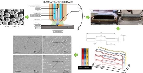
  • Two walls from Hastelloy with large dimensions could be produced by plasma transferred arc in air or argon conditions.
  • The atmosphere during the additive process presented lower impact on the final behavior than expected. The results of the thorough characterization of the specimens stated that their mechanical properties, as built, achieved values close to the standard ones, independently of the atmospheric conditions during the manufacturing.
  • There was no effect of the thermal treatments in the final behavior of the specimens. The heat treatments were insufficient to modify and to improve the mechanical properties.
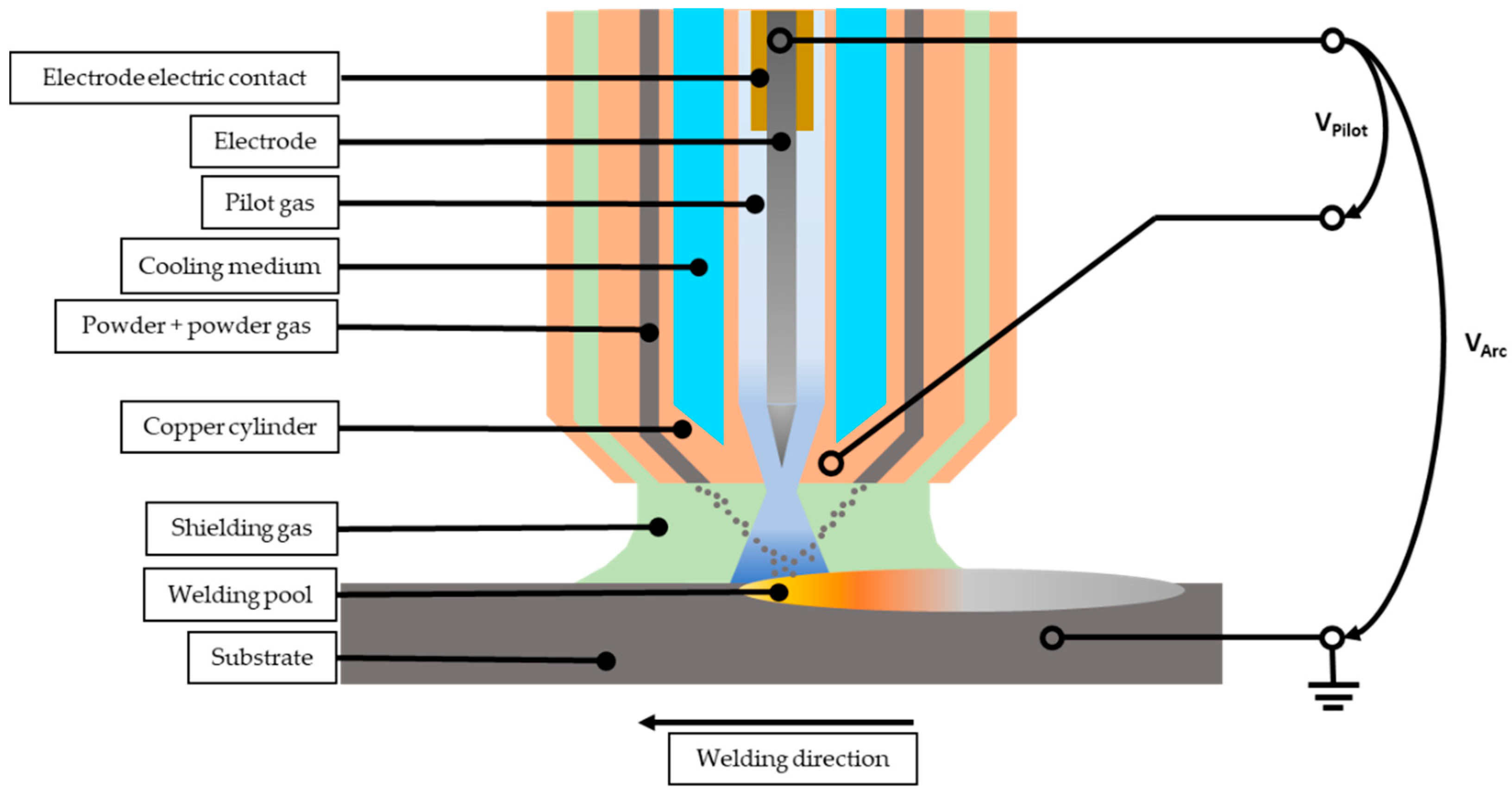
  • In general, there were observed Mo-rich precipitates in all the specimens caused by processing; variations of the distribution of theses precipitates could be related to the mechanical properties measured.

Author Contributions

All the authors collaborated to obtain high-quality research work. E.M.P.-S. carried out the mechanical properties and the tribological tests, and performed the metallographic preparation. E.A. built the specimens with the PTA and selected the references. C.A. was responsible for the microstructure characterization for specimens: Optical and electron microscopy. I.M.-M. analyzed the data and the relationship between processing parameters and material properties, and designed the structure of the paper. M.K. controlled the fabrication process. E.N. optimized the equipment and applications. All authors read and agreed to the published version of the manuscript.

Funding

This research received funding from the European Union Horizon 2020 Programme (H2020) under grant agreement no. 768612.

Acknowledgments

The authors want to thank the Universidad de Sevilla for the use of experimental facilitates at CITIUS, Microscopy and X-Ray Laboratory Services (PPIT-2018-I.5 EVA M. PÉREZ SORIANO). The authors also wish to thank the technicians Jesús Pinto, Mercedes Sánchez, and Miguel Madrid for their experimental assistance.

Conflicts of Interest

The authors declare no conflict of interest.

References

  1. Zhang, S.; Lane, B.; Whiting, J.; Chou, K. On thermal properties of metallic powder in laser powder bed fusion additive manufacturing. J. Manuf. Process. 2019, 47, 382–392. [Google Scholar] [CrossRef]
  2. Fina, F.; Goyanes, A.; Gaisford, S.; Basil, A.W. Selective laser sintering (SLS) 3D printing of medicines. Int. J. Pharmaceut. 2017, 529, 285–293. [Google Scholar] [CrossRef] [PubMed] [Green Version]
  3. Ríos, S.; Colegrove, P.A.; Williams, S.W. Metal transfer modes in plasma Wire + Arc additive manufacture. J. Mater. Process. Technol. 2019, 264, 45–54. [Google Scholar] [CrossRef]
  4. Barros, R.; Silva, F.J.G.; Gouveia, R.M.; Saboori, A.; Marchese, G.; Biamino, S.; Salmi, A.; Atzeni, E. Laser powder bed fusion of Inconel 718: Residual stress analysis before and after heat treatment. Metals 2019, 9, 1290. [Google Scholar] [CrossRef] [Green Version]
  5. Waqas, A.; Qin, X.; Xiong, J.; Zheng, C.; Wang, H. Analysis of ductile fracture obtained by charpy impact test of a steel structure created by robot-assisted GMAW-based additive manufacturing. Metals 2019, 9, 1208. [Google Scholar] [CrossRef] [Green Version]
  6. Herderick, E. Additive manufacturing of metals: A review. Mater. Sci. Technol. Conf. Exhib. 2011, 2, 1413–1425. [Google Scholar]
  7. Gibson, I. Additive Manufacturing Technologies: 3D Printing, Rapid Prototyping, and Direct Digital Manufacturing; Springer: Berlin, Germany, 2015. [Google Scholar]
  8. Vály, L.; Grech, D.; Neubauer, E.; Kitzmantel, M.; Baca, L.; Stelzer, N. Preparation of titanium metal matrix composites using additive manufacturing. Key Eng. Mater. 2017, 742, 129–136. [Google Scholar] [CrossRef]
  9. Mercado Rojas, J.G.; Wolfe, T.; Fleck, B.A.; Qureshi, A.J. Plasma transferred arc additive manufacturing of Nickel metal matrix composites. Manuf. Lett. 2018, 18, 31–34. [Google Scholar] [CrossRef]
  10. Sharples, R.V. The Plasma Transferred Arc (PTA) Weld. Surfacing Process; Welding Institute: Cambridge, UK, 1985. [Google Scholar]
  11. Alberti, E.A.; Bueno, B.M.P.; D’Oliveira, A.S.C.M. Additive manufacturing using plasma transferred arc. Int. J. Adv. Manuf. Technol. 2016, 83, 1861–1871. [Google Scholar] [CrossRef]
  12. Dinovitzer, M.; Chen, X.; Laliberte, J.; Huang, X.; Frei, H. Effect of wire and arc additive manufacturing (WAAM) process parameters on bead geometry and microstructure. Addit. Manuf. 2019, 26, 138–146. [Google Scholar] [CrossRef]
  13. ISO/ASTM 52900:2015 (ASTM F2792). Additive manufacturing-General principles-Terminology. International Organization for Standardization. Available online: https://www.iso.org/standard/69669.html (accessed on 14 January 2020).
  14. Hoefer, K.; Mayr, P. Additive Manufacturing of titanium parts using 3D plasma metal deposition. Mater. Sci. Forum 2018, 941, 2137–2141. [Google Scholar] [CrossRef]
  15. Rodriguez, J.; Hoefer, K.; Haelsig, A.; Mayr, P. Functionally graded SS 316L to Ni-based structures produced by 3D plasma metal deposition. Metals 2019, 9, 620. [Google Scholar] [CrossRef] [Green Version]
  16. Tabernero, I.; Paskual, A.; Álvarez, P.; Suárez, A. Study on arc welding processes for high deposition rate additive manufacturing. Procedia CIRP 2018, 68, 358–362. [Google Scholar] [CrossRef]
  17. Ho, A.; Zhao, H.; Fellowes, J.W.; Martina, F.; Davis, A.E.; Prangnell, P.B. On the origin of microstructural banding in Ti-6Al4V wire-arc based high deposition rate additive manufacturing. Acta Mater. 2019, 166, 306–323. [Google Scholar] [CrossRef]
  18. Chen, L.; Bai, S.L.; Ge, Y.Y.; Wang, Q.Y. Erosion-corrosion behaviour and electrochemical performance of Hastelloy C22 coatings under impingement. Appl. Surf. Sci. 2018, 456, 985–998. [Google Scholar] [CrossRef]
  19. Chen, L.; Bai, S.L. The anti-corrosion behaviour under multi-factor impingement of Hastelloy C22 coating prepared by multilayer laser cladding. Appl. Surf. Sci. 2018, 437, 1–12. [Google Scholar] [CrossRef]
  20. Han, Q.; Mertens, R.; Montero-Sistiaga, M.L.; Yang, S.; Setchi, R.; Vanmeensel, K. Laser powder bed fusion of Hastelloy X: Effects of hot isostatic pressing and the hot cracking mechanism. Mater. Sci. Eng. A Struct. 2018, 732, 228–239. [Google Scholar] [CrossRef]
  21. Wang, Q.Y.; Bai, S.L.; Zhao, Y.H.; Liu, Z.D. Effect of mechanical polishing on corrosion behavior of Hastelloy C22 coating prepared by high power diode laser cladding. Appl. Surf. Sci. 2014, 303, 312–318. [Google Scholar] [CrossRef]
  22. Molin, S.; Dunst, K.J.; Karczewski, J.; Jasinski, P. High temperature corrosion evaluation of porous Hastelloy X alloy in air and humidified hydrogen atmospheres. J. Electrochem. Soc. 2016, 163, C296–C302. [Google Scholar] [CrossRef]
  23. Tu, R.; Goto, T. Corrosion behavior of Hastelloy-XR alloy in O2 and SO2 atmosphere. Mater. Trans. 2005, 46, 1882–1889. [Google Scholar] [CrossRef] [Green Version]
  24. Hussain, N.; Qureshi, A.H.; Shahid, K.A.; Chugtai, N.A.; Khalid, F.A. High-temperature oxidation Behavior of Hastelloy C-4 in steam. Oxid. Met. 2004, 61, 355–364. [Google Scholar] [CrossRef]
  25. Bal, K.S.; Majumdar, J.D.; Choudhury, A.R. Effect of post-weld heat treatment on the tensile strength of laser beam welded Hastelloy C-276 sheets at different heat inputs. J. Manuf. Process. 2019, 37, 578–594. [Google Scholar] [CrossRef]
  26. Wang, F. Mechanical property study on rapid additive layer manufacture Hastelloy X alloy by selective laser melting technology. Int. J. Adv. Manuf. Technol. 2012, 58, 545–551. [Google Scholar] [CrossRef]
  27. ASTM B574. ASTM and SAE-AMS Standards and Specifications for Nickel Based Alloys; ASTM: West Conshohocken, PA, USA, 2018. [Google Scholar]
  28. Montero-Sistiaga, M.L.; Pourbabak, S.; Van Humbeeck, J.; Schryvers, D.; Vanmeensel, K. Microstructure and mechanical properties of Hastelloy X produced by HP-SLM (high power selective laser melting). Mater. Des. 2019, 165, 107598. [Google Scholar] [CrossRef]
Figure 1. Circular backscatter detector (CBS)-SEM image of the starting powder of supplied Hastelloy C-22.
Metals 10 00200 g001
Figure 2. Scheme of the plasma transferred arc (PTA) torch.
Metals 10 00200 g002
Figure 3. Flowability test of the Hastelloy C-22 powder on the PTA device.
Metals 10 00200 g003
Figure 4. Processing parameters test.
Metals 10 00200 g004
Figure 5. Oscillation bead on plate welding test.
Metals 10 00200 g005
Figure 6. Walls in as-built conditions: (a) Produced under air atmosphere, (b) produced under argon atmosphere.
Metals 10 00200 g006
Figure 7. Tensile test sample geometry (in millimeters) and positioning of tensile test samples extracted from the produced sample walls.
Metals 10 00200 g007
Figure 8. Thermal treatments applied to the specimens.
Metals 10 00200 g008
Figure 9. CBS-SEM images of Hastelloy C-22 specimens manufactured without thermal treatment (a,b), and in air (c,d) argon.
Metals 10 00200 g009
Figure 10. CBS-SEM images of Hastelloy C-22 specimen manufactured in air with thermal treatment, (a) thermal treatment 1 (TT1) (rapid air cooling (RAC)) and (b) TT2 water quenching (WQ).
Metals 10 00200 g010
Figure 11. SEM image of the Hastelloy C-22 specimen manufactured under air without thermal treatment and EDS analysis (analyzed specimen 1.2).
Metals 10 00200 g011
Figure 12. Mapping of specimen in air without thermal treatment (analyzed specimen 1.2): CBS-SEM (upper-left), Si, Mo, Cr, Mn, Fe, Ni, Cu.
Metals 10 00200 g012
Figure 13. Pattern diffraction of specimens produced in air conditions.
Metals 10 00200 g013
Figure 14. Pattern diffraction of specimens produced in argon conditions.
Metals 10 00200 g014
Figure 15. Friction coefficient vs. distance (m).
Metals 10 00200 g015
Table 1. Composition of Hastelloy C-22.
ElementSupplied Hastelloy C-22
[%wt.]
Standard Hastelloy C-22
[%wt.]
NiBal.Bal.
C0.007max. 0.015
Co0.40max. 2.50
Cr22.1120.00–22.50
Fe5.002.00–6.00
Mn0.65max. 0.50
Mo12.3712.50–14.50
Si0.91max. 0.08
V<0.02max. 0.35
W3.632.50–4.00
Table 2. Test processing parameters.
LayerCurrent
[A]
Travel Speed
[mm/min]
Feed Rate
[g/min]
112020013.5
214020013.5
318020013.5
422020013.5
512020011.0
612010011.0
714010011.0
816010011.0
914030029.0
1018030029.0
1122030029.0
1225040043.5
1314030011.0
1418040029.0
1518040024.5
1614030013.5
Table 3. Fabrication parameters for Hastelloy C-22 wall produced in air and in argon atmosphere.
SpecimenLayer NumberCurrent
[A]
Travel Speed
[mm/min]
Feed Rate
[g/min]
Two Hastelloy walls produced in air and in argon118040029.0
216050024.5
3–915060018.0
10–1615070013.5
Table 4. EDS composition for the Hastelloy C-22 specimen manufactured under air without thermal treatment.
ElementSpot 5
[%wt.]
Spot 3 in a Precipitate
[%wt.]
C K4.466.30
Si K0.842.53
W M1.815.63
Mo L8.7328.70
V K0.110.07
Cr K22.0417.80
Mn K1.430.79
Fe K4.702.79
Co K0.680.45
Ni K54.4134.59
Cu K0.800.36
Table 5. Mechanical and physical properties of the specimens produced in air atmosphere condition.
SpecimenTreatmentE [GPa]Yield Strength [MPa]UTS [MPa]Deformation [%]
1.1 As built209.30352.52611.8416.59
1.2 201.23334.46650.3724.04
1.3181.23309.97516.849.32
Average set 1 197.49332.32593.0216.65
2.1TT1158.21307.42715.8713.18
2.2135.33271.24717.4015.74
2.3147.47295.84547.383.89
Average set 2 147.00291.50660.2210.94
3.1TT2183.64298.92690.1310.89
3.2200.45307.52686.0812.29
3.3218.20303.95556.754.31
Average set 3 200.76303.46644.329.17
Table 6. Mechanical and physical properties of the specimens produced in argon atmosphere condition.
SpecimenTreatmentE [GPa]Yield Strength [MPa]UTS [MPa]Deformation [%]
1.1 As built167.18347.97620.2023.46
1.2 137.53336.75516.9011.51
1.3130.11329.71513.9012.26
Average set 1 144.94338.14550.3315.74
2.1TT1131.23348.52711.7215.22
2.2130.92350.08646.639.39
2.3155.37366.25625.527.96
Average set 2 139.18354.95661.2910.86
3.1TT2161.62365.35628.717.04
3.2152.37349.25604.396.86
3.3135.85337.09625.9810.50
Average set 3 149.95350.56619.698.13

