Article

Near Solidus Forming (NSF): Semi-Solid Steel Forming at High Solid Content to Obtain As-Forged Properties

1
Mechanical and Manufacturing Department, Mondragon Unibertsitatea, Loramendi 4, 20500 Mondragon, Spain
2
Automotive Intelligence Center (AIC), CIE Automotive, Parque empresarial Boroa P2-A4, 48340 Amorebieta, Spain
*
Author to whom correspondence should be addressed.
Metals 2020, 10(2), 198; https://doi.org/10.3390/met10020198
Submission received: 21 December 2019 / Revised: 27 January 2020 / Accepted: 28 January 2020 / Published: 30 January 2020
(This article belongs to the Special Issue Net-Shape Die Casting of Semi-solid Alloys)

Abstract

:
Near solidus forming (NSF) of steels is a novel process under the umbrella of semi-solid forming technologies midway between classical hot forging and semi-solid technologies. This article presents the work done at Mondragon Unibertsitatea to develop this technology and demonstrates the great potential of the NSF process. The study proves the capability of the process to reduce raw material consumption by 20%, reduce forming loads from 2100 t to 300 t, and reduce forming steps from three to one, to obtain as-forged mechanical properties, as well as the excellent repeatability of the process. The work demonstrates that manufacturing commercial steel components in a single step using several off-the-shelf alloys is possible thanks to the flowing pattern of the material, which enables near-net shaping. In the first part of the article, a general overview of the semi-automated near solidus forming cell, together with a description of the NSF manufacturing trials, is provided, followed by the presentation and discussion of the results for the selected steel alloys.

1. Introduction

Semi-solid metal processing (SSP) covers all the manufacturing routes involving semi-solid materials. Its origin lies in the discovery of the thixotropic behavior of metals (discovered by Spencer et al. [1]). This phenomenon is related to agglomeration/de-agglomeration phenomena depending on the application of shear inputs [2]. When shear stress is applied to a material in the semi-solid state, the particles separate from each other (de-agglomeration) to generate a material state consisting of a suspension of solid particles in a molten metal (liquid) matrix. The result of this effect is a reduction of viscosity due to the change in the material structure. Once the material is allowed to rest for a sufficient time interval, the particles begin to generate new bonds (agglomeration) to eventually restore the material’s initial state.
Based on this material behavior, different manufacturing routes have been developed in an attempt to make the leap to the industrialization of the process, mainly with low-melting-point alloys [3]. The high working temperatures of materials such as steels have hindered the investigation of SSP for those types of alloys, even though in 1979, Young et al. [4] conducted their first trials with some stainless steels. Nevertheless, it was not until the 1990s when research on the SSP of high-melting-point alloys gained momentum. A sign of that momentum can be seen in the steel cog wheels manufactured by Kapranos et al. [5] in Sheffield using this technology. From that point forward, various European universities and research centers began investigating how to successfully employ and gain the advantages of SSP of high-melting-point alloys with either low or high solid fractions [6].
In the latter case, at nearly 90% volume of solids, the main idea was to move closer to forging properties reducing the liquid phase and the working temperatures. Based on this perspective, various components were manufactured [7,8,9]. Nevertheless, neither the mechanical properties nor the die lifetime results were successful. From that point forward, those aspects have been the cornerstones of research on SSP industrialization of high-melting-point alloys.
To overcome the mechanical properties’ challenges and die lifetime problems, it is important to understand the material’s behavior at those conditions. Different material models have been proposed for the high solid fraction regime, mostly based on the thixotropic concept [10]. Nevertheless, after in-situ observation of the deformation of semi-solid material at high volumes of solid, several authors have suggested a granular material behavior [11,12] because of a lack of sufficient liquid phase being present. At these conditions, particle de-agglomeration does not lead to a suspension of solid particles in a liquid matrix but in interstitial holes that cannot be filled if there is not enough liquid because of the grain motion (translation and rotation). Consequently, the material stops behaving like a liquid and starts behaving more like a solid.
This could mean that, independently of the percentage of liquid in a material, if it is in the high solid fraction regime (above 90% for most materials), the material will behave granularly. However, the forces required to deform the material at either condition should still be low compared with hot forging. Moreover, the lower the liquid content, the better the final mechanical properties. In accordance with this hypothesis, recent work carried out in École Nationale Supérieure d’Arts et Métiers (ENSAM) [13,14] shows how, at solid fractions above 90%, the material still displays semi-solid behavior, enabling the filling of complex shapes while overcoming the die lifetime problem, as more than 3500 components have been successfully manufactured without any sign of severe die damage. Consequently, it seems that using high solid fraction conditions could solve the mechanical and die lifetime problem.
In the same way, the research group at Mondragon Unibertsitatea (MU) has demonstrated the possibility of successfully manufacturing steel components in a temperature range between 0.9 times the solidus temperature (TS) and at 5% liquid content. This implies that working temperatures below the solidus, measured by differential scanning calorimetry (DSC), where no liquid phase is expected to be present. Nevertheless, the semi-solid material behavior provides benefits in terms of reducing the raw material needed and lowering the energy consumption while assuring as-forged mechanical properties are achieved. As the processing conditions are new, the proposal of this novel-manufacturing route has been named “near solidus forming” (NSF) [15]. In the following pages, the process and the attained outcomes are explained.

2. Materials and Methods

2.1. The NSF Cell

The origins of the NSF cell come from the requirement for rapid forming speeds and final squeeze holding to perform the semi-solid forming (SSF) of aluminum alloys [16]. At that time, these requirements could only be fulfilled by hydraulic presses. However, a new kind of servo-motor-driven mechanical press (servo-mechanical press) was selected for the experiments as it satisfied the position control and speed performance requirements.
Looking at the potential this press offered in terms of widening the research capabilities, it allowed the leap to SSF high-melting-point alloys to be considered. However, the actual tooling designed for aluminum alloys was not considered appropriate to handle steels. The Advanced Materials and Forming Processes group of the engineering faculty of MU designed and fabricated the tooling for high-melting-point alloys and led the automation of a cell that consisted of induction equipment, a handling robot, and the servo-mechanical press (Figure 1) [17]. In the following section, each element of the cell is briefly described.

2.1.1. The Servo-Mechanical Press

The press is a 400 t AC servo-mechanical press from Fagor Arrasate, manufactured in Markina, Spain. The main differences between the hydraulic and servo-mechanical presses are the higher productivity, better product accuracy, and better machine reliability the latter gives. Moreover, its most important feature is the flexible ram movement that enables a wide range of working cycles even though, because of the movement of the connecting rod, the maximum press capacity is only available in the last stages of the ram movement. In the following table (Table 1), the main characteristics of the press are shown.

2.1.2. Induction Equipment

The induction heating method is one of the most effective methods for electrically heating conducting materials. It is based on inducing eddy currents in the billet that heat the material through the Joule effect and conductivity. In order to heat the billet homogeneously, a heating cycle comprising several stages was designed. The following are the characteristics of the induction equipment of the cell (Table 2).

2.1.3. Handling Robot

Controlling the temperature of the billet is of great importance for the successful forming in the semi-solid state, as temperature is a parameter that strongly influences the material’s behavior. Therefore, it is important to minimize any heat losses during the movement of the billet from the oven to the press. As a result, a six-axis robot with a self-designed grip (see [17]) was installed in the cell in order to ensure a fast and reproducible material transfer. The robot controller is also responsible for the overall coordination of the process, even if the induction furnace and the press have their own hardware for defining both the heating and deformation cycles.

2.1.4. Tooling for High-Melting-Point Alloys

Figure 1b shows the tooling designed at MU. It consists of an upper and lower die holder connected by four hydraulic cylinders that enable the opening and closing of the die. In the upper die holder, four other hydraulic cylinders ensure proper clamping to prevent the dies from separating during the process. Several flow dividers were installed to ensure that all the cylinders move at the same speed and time.

2.2. The NSF Process

This section is devoted to a systematic description of the NSF process. Before manufacturing, dies are preheated to 270 °C using oil flowing through tempering channels, sprayed with a long-lasting ceramic varnish with lubricant effects that also acts as a thermal shock barrier (Ceraspray®), as is the punch (Pierret et al. [18]). The dies are then closed and clamped, ready to start the manufacturing process.

2.2.1. Heating of the Billet

As already mentioned in Section 2.1.2, a multi-stage induction heating process was designed following the recorded temperatures of two type S thermocouples placed in the center and on the surface of the billet (Figure 2). Using a constant power of 24 kW and an argon flow of 14–20 dm3/min to avoid scale formation, the heating cycles were modified and optimized for each steel grade.
Table 3 lists all parameters mentioned in earlier sections. Note that temperatures recorded throughout the billet at the end of the induction heating are lower than the solidus ones for all the steels that were tested. A recorded forming stage example relating to press forces, ram speeds, and ram positions is shown in Figure 3.

2.2.2. Transfer and Deformation Stages

Once the billet has been completely heated, the robot takes the billet and places it in the press. The transfer time is approximately 12 to 14 s, which implies a temperature loss on the surface of approximately 40 °C, while maintaining the required temperature inside the billet. After placing the billet in the tooling, when the robot leaves the press, the deformation stage begins.
The deformation stage consists of moving the punch at the maximum speed from the top dead center (TDC) to the bottom dead center (BDC) of the ram. The ram position is defined considering that the stroke of the press is 400 mm and that the maximum load is only attained at the last displaced distances. In this case, the punch is maintained at the BDC, compressing the material for 5 s. An example of a cycle is shown in Figure 3.
Because of the ram deceleration when approaching the BDC, the speed decreases in the last stages of displacement. Therefore, the speed obtained is the maximum the press can reach. When the material starts to deform, the ram speed is close to 410 mm/s. Figure 3 shows a standard deformation step used with all the selected steels. Typically, the registered maximum loads were approximately 300 t. This indicates that the recorded forces are much more influenced by the geometry of the component than by the selected materials; thus, peak forces mainly represent die filling and not the resistance of the deformed material.

2.2.3. Component Ejection

Once the deformation stage has finished and the ram is at the TDC, the clamping system retraction and die opening are manually activated in order to eject the component. Once the dies are fully separated, the pneumatic ejection system of the press is manually activated to eject the component. Then, an operator is responsible for removing the component from the press and cleaning the dies to start a new cycle.

2.3. Geometries

An automotive spindle, acting as a short axle, is responsible for attaching the wheel assembly to the steering system. It pivots between the upper and lower A-frames or on the strut. Both the inner and outer wheel bearings ride on the spindle. The retaining nut on the end secures the wheel into position. The component usually acts as the frame in which the brake caliper is fixed. Automotive spindles are typically forged, as they must be extremely strong and durable to support the weight of the vehicle. Figure 4a shows schematically an assembly example.
The two spindle geometries used in this work are shown in Figure 4b,c. Considering that the disposition of the dies implies a downward flow of the material that is required to fill the cavity of the spindle, the complexity difference between both lies in the larger material flow through a thinner cross-section in the direction perpendicular to the axle (Figure 4b).
In any case, both geometries correspond to very complex shapes according to EN 10243-1. The R component weighs ~3 kg in comparison with the ~2.3 kg of the H component. Therefore, the initial billet for the H component is slightly smaller.

2.4. Materials

Four different steel grades for NSF are presented in this work.
The main goal is to demonstrate that NSF is an alternative process for manufacturing complex components in a single step with as-forged mechanical properties while reducing raw material consumption and forming forces. It is also important to confirm that off-the-shelf materials are suitable for the NSF process. Thus, we have selected the 42CrMo4 and S48C alloys, which are utilized in conventional hot forging, to manufacture the R and H spindles. The third material is a micro-alloyed steel (in this case the 44MnSiVS6) that enables the removal of the post-processing heat treatment if certain cooling conditions are met. Finally, in an attempt to observe the influence a coarse and as-cast microstructure could have on the process itself, an EN 13262-ER7-grade steel used for the manufacturing of train wheels was used.

2.4.1. 42CrMo4

The 42CrMo4 steel grade (steel number 1.7225) is a commercially available quenching and tempering alloy commonly used in aeronautics and automotive industries. The steel grade was supplied by Sidenor, located in Basauri (Spain), in cylindrical bars after hot rolling and quenching and tempering heat treatment. The following table (Table 4) shows its chemical composition.

2.4.2. S48C

The S48C steel grade (steel number 1.1191) is a quenching and tempering medium carbon steel commonly used in the automotive industry for axles, gears, and differentials manufacturing. The material was supplied by Sidenor in round bars after hot rolling. The steel composition is shown in the following table (Table 5).

2.4.3. 44MnSiVS6

Micro-alloyed steels are alloys composed of many different elements in small quantities (such as Nb, V, Zr, Ti) that give different properties to the material. These kinds of alloys are situated between mild- and low-alloy steels in performance and cost. Because of their chemical composition, they can be designed to have great strengths (more than 1000 MPa) and they offer the possibility of attaining the same mechanical properties as quenching and tempering steels by controlling the cooling in hot working conditions.
The selected 44MnSiVS6 steel (steel number 1.5233) is a micro-alloyed medium carbon forging steel with one of the highest tensile strengths in its family (1100 MPa). The material was supplied by Sidenor in cylindrical bars after hot rolling. The chemical composition of this steel is shown in the following table (Table 6).

2.4.4. EN 13262-ER7-Grade Steel

This steel family is designed for train wheels. Due to confidentiality issues, the exact composition cannot be shown. However, an indicative composition can be seen in Table 7. The material was supplied by CAF in cylinders of 330 mm diameter, and it was submitted to an annealing treatment at a temperature below 540 °C.

3. Results

All of the materials presented above were subjected to the NSF process following the instructions described in Section 2.2. Figure 5 displays the difference between classical hot forging and NSF of the H spindle. There are three necessary forging steps plus a flash removal operation, involving additional equipment; in hot forging, while using NSF, a single step is enough. This implies the reduction of raw material consumption avoiding the flash. In this example, it means that the starting weight of the billet is reduced by 20%. Note that the final figure of the hot forging process has been submitted to a shot blasting operation while the NSF component is as obtained directly from the forming step.
The case of the R spindle is similar. The number of forging steps is reduced from three to one and raw material consumption reduced by 20%. As shown in Table 8, forming loads are drastically reduced in both cases. The hot forging loads correspond to the second step, in which maximum peak loads are measured. Loads measured for the 44MnSiVS6 and EN 13262-ER7 are also in the same range (see Section 3.3 and Section 3.4), but as they are not used in hot forging, they are not included in Table 8.
The two geometries presented in this work (Figure 6) are the same as those commercially manufactured by hot forging. Consequently, and for that reason, it is not possible to report any component’s weight reduction or geometrical optimization. These are topics under research in actual running projects.
The above results demonstrate that NSF can achieve important raw material savings and reduced forming loads using off-the-shelf materials that are already in use in traditional processes. This implies no extra costs in materials and secondary processes, which makes NSF even more attractive for industrial applications.
After the process was completed, the 42CrMo4 and S48C steel grades were heat-treated and mechanically tested under the same conditions as the commercial hot-forged components to obtain a direct comparison between both processes. The specimens machined for tensile (Figure 7a) and fatigue (Figure 7b) tests, according to ASTM E8M-09 and ASTM E466-96, respectively, were taken from the axle of the components (Figure 7).
The case of the other two steels is slightly different. The selected commercial components are not manufactured using these steel grades. However, the possibility of avoiding the post-processing heat treatment in the case of the micro-alloyed steels makes them good candidates for hot forging and, therefore, for NSF. Regarding the EN 13262-ER7 steel, the objective was to confirm that processing by NSF straight from the as-cast condition is possible. Thus, only microstructural analysis was carried out to observe and analyze the influence of the process on each case. In the following lines, the results are explained, categorized by steel grade.

3.1. 42CrMo4

This alloy is used to commercially manufacture the R spindle by hot forging. Consequently, in order to have a direct comparison between both processes, this steel grade was the first choice. NSF components have been successfully manufactured recording a maximum peak load of 302.7 t. After the process was completed, the components were subjected to the same quenching and tempering heat treatment used for the hot-forged components in CIE Automotive’s facilities.
Figure 8 a,b shows the final microstructure of the axle area after heat-treating the hot-forged and NSF components, respectively. In both cases, a microstructure formed by tempered martensite is visible with a grain size of nine (ASTM E–112). The only difference is the slightly smaller partial decarburization depth present in the NSF components.
Table 9 shows the mechanical requirements for the hot-forged (HF) components and the average mechanical properties obtained by NSF.

3.2. S48C

This alloy is used to commercially manufacture the H spindle by hot forging. Therefore, as in the previous case, to enable a direct comparison between both processes, we selected the same steel grade for NSF. The parts were successfully manufactured with a maximum peak load of 271.5 t. In the same fashion as with the 42CrMo4, the components were subjected to the quenching and tempering heat treatment used in the forging company, CIE Automotive, for the S48C.
Figure 9 displays the final microstructure of the axle area of the H spindle. In this case, the hot-forged microstructure is formed by ferrite and pearlite while the NSF structure presents a higher amount of bainite. In both cases, the grain size is 10 (ASTM E112) and, as in the 42CrMo4 case, the decarburization depth is slightly lower in the case of the NSF components.
In terms of tensile properties, presented in Table 10 both processes produce very similar results. The yield strength is slightly higher in the NSF components and the ultimate tensile strength is slightly higher in the hot-forged ones. Looking at the results, the most remarkable difference is the elongation, which is higher in the NSF parts.
NSF allowing fatigue analysis performed for comparing the dynamic resistance of hot-forged and NSF components was carried out using a small pre-industrial batch of 250 components. This fatigue analysis was not carried out based on conventional fatigue models such as the one by Basquin [19]. Those models require a large number of tests to reach an acceptable approximation of the reality and, even so, they exhibit a considerable dispersion as no probabilistic approaches are considered.
At present, there are some alternatives, such as the probabilistic fatigue model developed by Castillo and Fernández-Canteli [20]. This model fulfills the physical principles, the weakest link principle, and the statistic conditions related to the extreme values theory. This last consideration is in turn of particular relevance in fatigue phenomena as high dispersions are usually present. This makes it possible to attain an acceptable S/N curve even if only a few tests are carried out. Consequently, based on this last model, ProFatigue software [21] was utilized. Figure 10 shows the obtained results. Analyzing the obtained data, it is possible to confirm that components manufactured by classic hot forging and NSF have similar fatigue behavior. Note that “Pf” means the probability of fracture happening below the curve.

3.3. 44MnSiVS6

As described earlier, micro-alloyed steels enable the omission of post-processing heat treatment if certain cooling conditions are met after the forming step. The 44MnSiVS6 alloy offers the possibility of obtaining ultimate tensile strengths of approximately 1000 MPa. In order to implement this advantage in the NSF process, it is necessary to check if the material is suitable for the process.
To check the latter point, the R spindle geometry was used. The recorded maximum peak load during the deformation stage was 275.2 t, demonstrating that this micro-alloyed steel can also be shaped by NSF.
Once the component is formed, it is necessary to meet the required cooling conditions and eject the component as quickly as possible to obtain the appropriate ferrite–pearlite microstructure. After opening the dies and ejecting the part, the component was allowed to air cool to avoid high cooling rates entailing generation of bainite or martensite.
After analyzing the microstructure of the component, the desired ferrite–pearlite microstructure was observed (Figure 11). In the axle zone (Figure 11c), Widmanstätten ferrite can be observed. This results from somewhat rapid cooling. In the rest of the component, the expected ferrite–pearlite microstructure was obtained.
The difference between Zones 1 and 2 of Figure 11a is the grain size. In Zone 1, grains of the order of 22 µm were noticed, whereas in Zone 2, grains of closer to 100 µm were seen. This results from the strain differences between the distinct sections of the material. In those areas where the material came into contact with the punch or the die (Zone 1), higher deformations occurred. When moving away from the surface, a lower degree of deformation took place and, therefore, thicker grains were generated (Zone 2). Note that Figure 11a is a cut of the bottom part of the component in a direction perpendicular to the axle.

3.4. EN 13262-ER7

Finally, yet importantly, an EN 13262-ER7 steel alloy was used to observe the influence a coarse and as-cast microstructure could have on the NSF process itself using the R spindle geometry. The components were successfully manufactured recording a peak load of 291.9 t. Therefore, it seems that, at the studied manufacturing conditions, the grain size, and material history do not greatly matter in terms of material deformation capabilities. Moreover, after analyzing the microstructure of the axle of the component, substantial grain refinement can be observed (Figure 12b) in comparison with the as-supplied ferritic pearlitic microstructure with grains of the order of millimeters shown in Figure 12a.

4. Discussion

The main goal of this paper is to present the NSF process and its capabilities. With that purpose in mind, the NSF cell was described and the process parameters defined to produce the R and H spindles in a unique step, without flash, and with reduced forming loads.
The recorded forces are much more influenced by the geometry of the component than by the selected materials. Thus, peak forces mainly represent press frame deformation once the die is filled and not the resistance of the material to be deformed. However, regarding process capabilities, as the geometries presented in this work (Figure 6) are the same as those commercially manufactured by hot forging, it is not possible to report any component’s weight reduction or geometrical optimization. Those are topics under research in actual running projects.
Concerning the selected steel alloys presented, the 42CrMo4 and S48C grades were selected to determine if hot forging requirements could be achieved. Both steels were off-the-shelf materials utilized to commercially manufacture the R and H spindles, respectively, by hot forging and have been subjected to the same mechanical tests as those from the industry. In the case of the 42CrMo4, Table 8 shows that NSF complies with the Original Equipment Manufacturer’s requirements. Regarding S48C, hot-forged and NSF properties are essentially the same, as demonstrated in Table 9 and Figure 9. These results demonstrate that manufacturing components by NSF with as-forged properties is possible. What still needs to be done with the 42CrMo and S48C relates more to the industrialization process. In any case, the thermal treatment of the S48C can be optimized, thus the mechanical results will be improved, but in terms of process comparison, nothing will change as it is directly related to the material and not to the process.
The third alloy, the 44MnSiVS6, enables removal of the post-processing heat treatment if certain cooling conditions are met. The objective of using this steel grade was simply to demonstrate that micro-alloyed steels are also suitable for NSF. The first step, to analyze its suitability, was to determine if it could be deformed under the defined NSF conditions. After confirming this, the microstructure was analyzed to determine if the required ferrite–pearlite microstructure could be obtained. Figure 11 shows that in the actual conditions, a ferrite–pearlite microstructure is obtained in the massive area of the R spindle while ferrite Widmanstätten is obtained in the axle zone. This is due to the clamping system of the tooling. During manufacturing, dies are tempered with recirculating oil and, as the opening of the dies is not fast enough, the component is in contact with dies longer than necessary, changing the cooling conditions and preventing the microstructure from completely obtaining the desired one.
Finally, an EN 13262 ER7-grade steel was used to confirm that as-cast steels could also be good candidates to be processed by NSF. Thus, the selected steel grade was successfully manufactured by NSF and it was concluded that the grain size and material history do not greatly matter at those process conditions.

5. Conclusions

The results obtained demonstrate that manufacturing components by NSF is possible for different steel alloys and that the process is sufficiently robust. It is a real and reliable alternative to classic hot forging and good temperature control with excellent process repeatability is obtained.
NSF has demonstrated great potential to reduce manufacturing costs, minimizing material and energy consumption, and obtaining as-forged mechanical properties.
The material’s flowing pattern enables near-net shaping of complex geometries in a single step. Furthermore, the possibility of using off-the-shelf materials that are already in use in classic processes implies no extra costs in materials and secondary processes. This makes NSF even more attractive for industrial applications.
To explore the full potential of this technique, it is necessary to deepen the knowledge of the material flowing behavior in order to be able to redesign components and enhance light-weighting.

Author Contributions

J.L., G.P., I.H. and A.S. are members of the Advance Materials and Forming Processes research group at Mondragon Unibertsitatea. They are responsible for developing the NSF technology from the initial conceptual idea to the final implementation. Their work covers the entire process chain: material characterisation and behaviour at process temperatures, process simulation, tooling design and manufacturing and validation of the components. I.L. is Engineering Director in CIE Automotive. CIE Automotive is the hot forging company that provides the traditional spindles. He is involved in the NSF component’s redesign, process simulation, heat treatments after manufacturing and machining and final validation of the components. All authors have read and agreed to the published version of the manuscript.

Funding

This research was funded by the Etorgai program of the Department of Industry, Innovation, Trade and Tourism of the Basque Government and Centro para el Desarrollo Tecnológico Industrial (CDTI) of the Ministry of Science, Innovation and Universities of the Spanish Government.

Acknowledgments

The authors would like to sincerely thank CIE Automotive; Sidenor I+D; the Department of Industry, Innovation, Trade and Tourism of the Basque Government; and the Ministry of Industry, Tourism and Trade of the Government of Spain for their economic support.

Conflicts of Interest

The authors declare no conflicts of interest.

References

  1. Spencer, D.B.; Mehrabian, R.; Flemings, M.C. Rheological behavior of Sn-15 pct Pb in the crystallization range. Metall. Trans. 1972, 3, 1925–1932. [Google Scholar] [CrossRef]
  2. Quaak, C.J. Rheology of Partially Solidified Aluminium Alloys and Composites. Ph.D. Thesis, Technische Universiteit Delft, Delft, The Netherlands, January 1996. [Google Scholar]
  3. Kirkwood, D.H.; Suéry, M.; Kapranos, P.; Atkinson, H.V.; Young, K.P. Semi-solid Processing of Alloys; Springer: Berlin/Heidelberg, Germany, 2010; ISBN 978-3-642-00705-7. [Google Scholar]
  4. Young, K.P.; Riek, R.G.; Flemings, M.C. Structure and properties of Thixocast steels. Met. Technol. 1979, 6, 130–137. [Google Scholar] [CrossRef]
  5. Kapranos, P.; Kirkwood, D.H.; Sellars, C.M. Semi-solid processing of tool steel. J. Phys. 1993, 4, 835–840. [Google Scholar] [CrossRef]
  6. Rassili, A.; Atkinson, H.V. A review on steel thixoforming. Trans. Nonferrous Met. Soc. China 2010, 20, s1048–s1054. [Google Scholar] [CrossRef] [Green Version]
  7. Cezard, P.; Sourmail, T. Thixoforming of Steel: A State of the Art from an Industrial Point of View. Solid State Phenom. 2008, 141–143, 25–35. [Google Scholar] [CrossRef]
  8. Püttgen, W.; Bleck, W.; Hirt, G.; Shimahara, H. Thixoforming of steels—A status report. Adv. Eng. Mater. 2007, 9, 231–245. [Google Scholar] [CrossRef]
  9. Rassili, A. A review on thixoforming of high melting point alloys. Solid State Phenom. 2016, 256, 228–236. [Google Scholar] [CrossRef]
  10. Atkinson, H.V. Modelling the semisolid processing of metallic alloys. Prog. Mater. Sci. 2005, 50, 341–412. [Google Scholar] [CrossRef] [Green Version]
  11. Karagadde, S.; Lee, P.D.; Cai, B.; Fife, J.L.; Azeem, M.A.; Kareh, K.M.; Puncreobutr, C.; Tsivoulas, D.; Connolley, T.; Atwood, R.C. Transgranular liquation cracking of grains in the semi-solid state. Nat. Commun. 2015, 6, 8300. [Google Scholar] [CrossRef] [Green Version]
  12. Gourlay, C.M.; Dahle, A.K. Dilatant shear bands in solidifying metals. Nature 2007, 445, 70–73. [Google Scholar] [CrossRef]
  13. Balan, T.; Becker, E.; Langlois, L.; Bigot, R. A new route for semi-solid steel forging. CIRP Ann. Manuf. Technol. 2017, 66, 297–300. [Google Scholar] [CrossRef]
  14. Becker, E.; Bigot, R.; Rivoirard, S.; Faverolle, P. Experimental investigation of the thixoforging of tubes of low-carbon steel. J. Mater. Process. Technol. 2018, 252, 485–497. [Google Scholar] [CrossRef]
  15. Plata, G. Semi-Solid Forging of Steels: New Insights into Material Behaviour Evolution and Industrialization. Ph.D. Thesis, Mondragon Unibertsitatea, Mondragón, Spain, December 2018. [Google Scholar]
  16. Azpilgain, Z.; Ortubay, R.; Blanco, A.; Hurtado, I. Servomechanical Press: A New Press Concept for Semisolid Forging. Solid State Phenom. 2008, 141–143, 261–266. [Google Scholar] [CrossRef]
  17. Lozares, J. Semisolid Forging of Steel Components for Automotive Industry. Ph.D. Thesis, Mondragon Unibertsitatea, Mondragón, Spain, April 2014. [Google Scholar]
  18. Pierret, J.C.; Rassili, A.; Vaneetveld, G.; Bigot, R.; Lecomte-Beckers, J. Friction coefficients evaluation for steel thixoforging. Int. J. Mater. Form. 2010, 3, 763–766. [Google Scholar] [CrossRef]
  19. Basquin, O. The exponential law of endurance tests. Proc. Am. Soc. Test Mater. 1910, 10, 625–630. [Google Scholar]
  20. Castillo, E.; Fernández-Canteli, A. A Unified Statistical Methodology for Modelling Fatigue Damage; Springer: Dordrecht, The Netherlands, 2009; ISBN 978-1-4020-9182-7. [Google Scholar]
  21. Fernández-Canteli, A.; Przybilla, C.; Nogal, M.; Aenlle, M.L.; Castillo, E. Profatigue: A software program for probabilistic assessment of experimental fatigue data sets. Procedia Eng. 2014, 74, 236–241. [Google Scholar] [CrossRef]
Figure 1. (a) The near solidus forming (NSF) cell of Mondragon Unibertsitatea (MU) and (b) the self-designed NSF tooling for high-melting-point alloys.
Metals 10 00198 g001
Figure 2. Billet dimensions (mm) and thermocouple location to record the temperature during the heating cycles.
Metals 10 00198 g002
Figure 3. Example of the press force, ram position, and ram speed during the NSF process.
Metals 10 00198 g003
Figure 4. CAD drawing of (a) the rear suspension with the spindle in violet, (b) the R spindle (~3 kg), and (c) the H spindle (~2.3 kg).
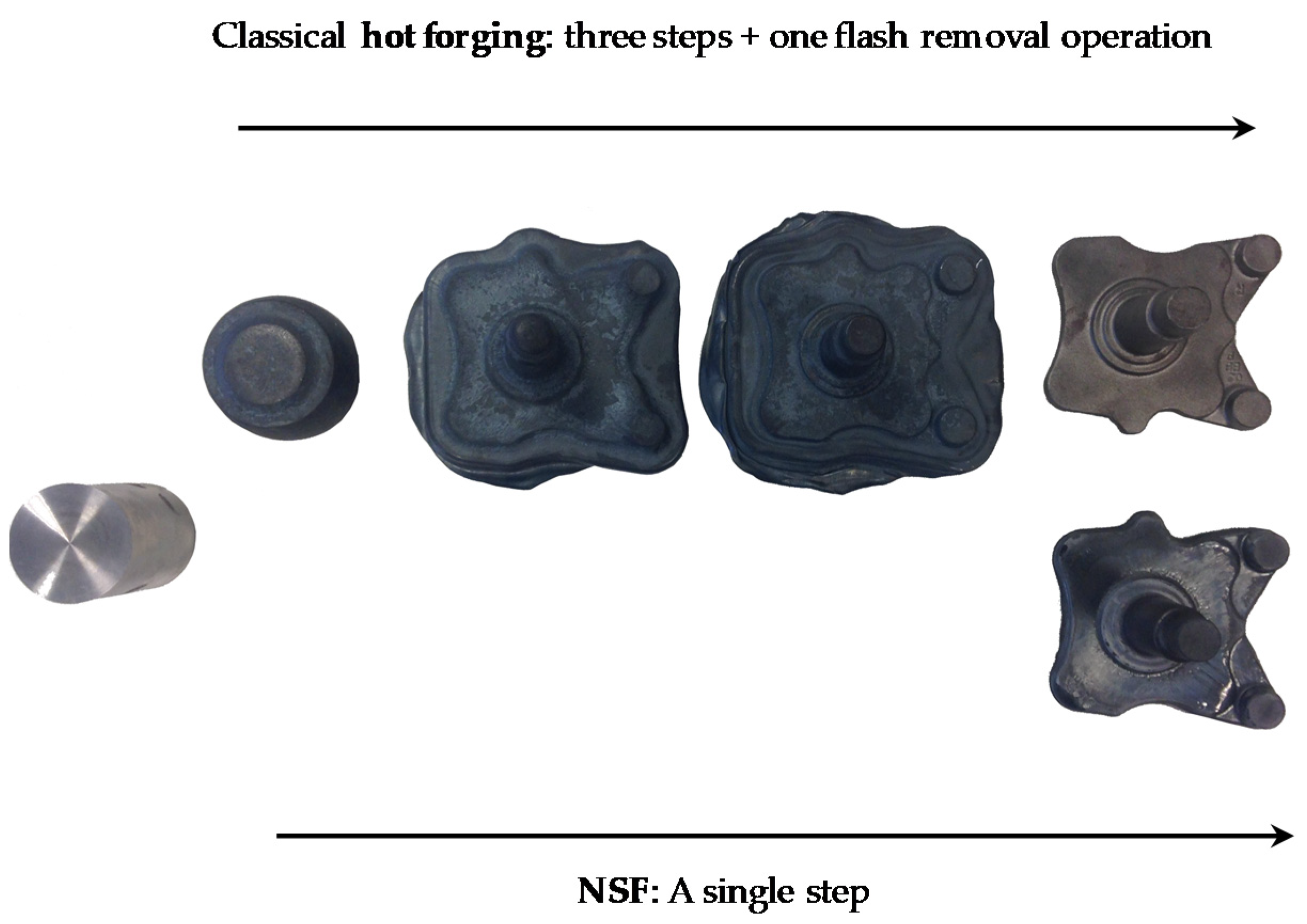
Metals 10 00198 g004
Figure 5. A comparison of the required forming steps to get the H spindle by hot forging and NSF.
Metals 10 00198 g005
Figure 6. R and H components obtained using the NSF process.
Metals 10 00198 g006
Figure 7. Schematic illustration of the location from which the specimens were taken and the geometry for (a) tensile and (b) fatigue tests. All dimensions are in mm except the roughness in µm.
Metals 10 00198 g007
Figure 8. Microstructure of the axle area of the 42CrMo4 steel grade after heat-treating the hot-forged (a) and NSF (b) components. Scale bar: 30 µm.
Metals 10 00198 g008
Figure 9. Microstructure of the axle area of the S48C steel grade after heat-treating the hot-forged (a) and NSF (b) components. Scale bar: (a) 30 µm and (b) 100 µm.
Metals 10 00198 g009
Figure 10. Comparison of the fatigue Pf = 50% curves of the hot-forged and NSF components.
Metals 10 00198 g010
Figure 11. The manufactured semi-solid forming (SSF) component of 44MnSiVS6 cut in half and the microstructures at different positions: (a) bottom, (b) middle, and (c) axle. The scale bar means 5 mm for (a) and 100 µm for (b) and (c).
Metals 10 00198 g011
Figure 12. As-supplied structure of the EN 13262-ER7-grade steel (a) and microstructure of the axle area after the NSF process (b). Scale bar: 500 µm.
Metals 10 00198 g012
Table 1. Characteristics of the 4000 kN servo-motor-driven mechanical press.
Servo-Motor-Driven Mechanical Press SDM2-400-2400–1200
Press capacity (kN) 4000 at 20 mm from the “Bottom Dead Center”
Number of points2
Working torque max/nominal (N.m)5500/3000
Max stroke (mm)400
Max ram speed (mm/s)800
Die height (mm)1000 to 1200 (stroke 400 mm)
Stroke adjustment (mm)200
Table size (mm x mm)2400 × 1200
Max cadence (spm)100
Die cushion capacity (kN)400
Die cushion stroke (mm)100
Motor power max/nominal (kW)450/250
Table 2. EFD induction heating equipment characteristics.
EFD Induction Furnace
Power max.150 kW
Frequency1.7–3 kHz
Atmosphere gasArgon
Table 3. Die temperature, lubricant, argon flow, solidus temperature (TS), heating power, and temperature of the billet at the end of the heating cycle (TH) for each tested steel.
MaterialTs (°C)TH (°C)Die T (°C)LubricantArgon (dm3/min)Power (kW)
42CrMo414081360270Ceraspray®14–20 24
S48C13971350
44MnSiVS613941345
EN 13262-ER713641325
Table 4. Chemical composition in wt % of the 42CrMo4E steel grade.
CMnSiPSCrNiMo
0.420.800.250.0110.0241.080.100.21
Table 5. Chemical composition in wt % of the S48C steel grade.
CMnSiPSCrNiCu
0.480.820.270.0190.0240.160.150.21
Table 6. Chemical composition in wt % of the 44MnSiVS6 micro-alloyed steel.
CMnSiPSCrNiMoVTi
0.451.210.890.0070.0290.100.080.0140.270.013
Table 7. Chemical composition in wt % of the EN 13262-ER7 steel.
CMnSiPSCrNiMoVCu
0.520.800.400.020.0150.300.300.080.060.30
Table 8. Comparison of forming steps, press capacity, peak forces, and raw material needed to manufacture the R and H spindles by hot forging and NSF.
ComponentSpindle MaterialProcessStepsPress Capacity (t)Peak Force (t)Material (kg)
R Spindle42CrMo4EHF3 + 1250012003.5
NSF14003002.8
H SpindleS48CHF3 + 1350021003
NSF14002802.4
Table 9. Hot forging (HF) requirements for the 42CrMo4 and average mechanical properties obtained by NSF after the same quenching and tempering heat treatment.
Manufacturing ProcessRe (MPa)Rm (MPa)Elongation (%)
HF≥8851030 ÷ 1130≥11
NSF945107313.3
Table 10. Average mechanical properties of hot-forged (HF) and NSF components after the same heat treatment.
SampleRe (MPa)Rm (MPa)Elongation (%)
HF493807.916.6
NSF502771.121.1

