Abstract
The purpose of this study was to demonstrate the novel technique of laser deposition of Fe-based powder under cryogenic conditions provided by a liquid nitrogen bath. Comparative clad layers were produced by conventional laser cladding at free cooling conditions in ambient air and by the developed process combining laser cladding and laser gas nitriding (hybrid) under cryogenic conditions. The influence of process parameters and cooling conditions on the geometry, microstructure, and hardness profiles of the clad layers was determined. The optical microscopy (OM), scanning electron microscopy (SEM), energy-dispersive spectrometer (EDS), and XRD test methods were used to determine the microstructure and phase composition. The results indicate that the proposed technique of forced cooling the substrate in a nitrogen bath during the laser deposition of Fe-based powder is advantageous because it provides favorable geometry of the clad, low dilution, a narrow heat-affected zone, a high hardness and uniform profile on the cross-sections, homogeneity, and refinement of the microstructure. The influence of the forced cooling on microstructure refinement was quantitatively determined by measuring the secondary dendrite arm spacing (SDAS). Additionally, highly dispersed nanometric-sized (200–360 nm) precipitations of complex carbides were identified in interdendritic regions.
1. Introduction
The laser beam as a heat source is widely used in different technologies of material processing and manufacturing, such surface treatment, coatings, or cutting and joining [1,2,3,4,5,6,7,8]. This is because the laser beam offers many advantages, the most important of which are high flexibility, high power densities, localized or selective heating, high processing speed, and low heat input [9,10,11,12,13,14,15]. One of the areas of laser beam application that is currently being widely developed is shaping the properties of surface layers and manufacturing of coatings for enhanced wear characteristics (e.g., corrosion, tribological, abrasive, thermal, and mechanical fatigue or impact load) [16,17,18,19,20,21].
Laser cladding and different methods of laser surface modification of different materials have been widely studied and much information in this area can be found in the worldwide literature. For example, an interesting and original technique of laser cladding under high frequency micro-vibration was developed and presented by Li et al. [22]. Many researchers point to several advantages of laser cladding over other methods of coatings [23,24,25,26,27]. However, current trends to ensure the highest energy efficiency of machines and devices, including the durability and reliability of machine components and tools, force the search for new or improved materials, as well as for new methods of their manufacturing, to overcome the limitations of current technologies. For this reason, a growing tendency to develop composite or hybrid materials and hybrid processes can be noticed [28,29]. The hybrid process combines at least two different machining processes carried out simultaneously in the same processing area (e.g., one weld pool in the case of fusion welding processes).
Among the metallic materials providing good wear resistance in various conditions, there are alloys based on Ni, Co, and Fe. However, due to the high costs, especially of Co-based alloys and additionally environmental restrictions, the interest in Fe-based alloys is increasing [30]. Sadeghimeresht et al. demonstrated that the FeCr type coatings show high corrosion resistance; thus, such coatings can be recommended as a potential alternative to Co-based coatings [30]. Wang et al. investigated the effect of V and Cr in Fe-based coatings produced by laser cladding [31]. They showed that high-quality coatings with high hardness (over 60 HRC) and wear resistance can be produced. Zhu et al. demonstrated the beneficial effect of Low-Temperature Tempering on the microstructure and properties of martensitic stainless steel coatings produced by laser cladding [32]. They proved that the post-treatment leads to martensite decomposition into finer tempered martensite with precipitations of numerous nano-sized Fe3C carbides [32]. Chen et al. investigated the laser cladding of Fe-based coatings on rotating shafts made of 35CrMo steel, working in the seawater environment [33]. They successfully produced high-quality coatings characterized by high hardness and better corrosion resistance compared with the base metal of the substrate [33].
Another interesting example of manufacturing a high performance Fe-based coating is the study conducted by Li et al. [34], which was an investigation of the effect of carbon fibers addition to Fe-based coatings produced by laser cladding. They demonstrated a significant increase in the microhardness and wear resistance of the composite coatings containing also nano-size carbides [34].
Hou et al. investigated the influence of scanning speed during the laser cladding of Fe-based amorphous coatings on the microstructure and properties of coatings [35]. They demonstrated that the laser cladding process could be successfully applied for manufacturing high-quality amorphous coatings. They also demonstrated that the low cost of Fe-based amorphous alloys is an advantage [35]. Zhang et al. demonstrated that deep cryogenic treatment, applied after laser cladding Fe-based coatings, can significantly enhance the microhardness and wear resistance of such coatings [36].
An original technique of laser surface melting of non-ferrous alloys in liquid nitrogen was elaborated and demonstrated by Zieliński et al. [37,38,39] and Cui et al. [40]. All these researchers point to the benefits of accelerated cooling and solidification rates due to liquid nitrogen-assisted cooling, which results in refinement of the microstructure. For example, Zieliński et al. reported that the laser surface melting of titanium alloy at cryogenic conditions resulted in obtaining a very hard surface layer composed of titanium nitrides and martensite structure saturated with nitrogen [37].
Cui et al. conducted laser surface melting of magnesium alloy also at cryogenic conditions provided by a liquid nitrogen bath. Cui et al. indicated that thanks to the rapid quenching associated with the process, the microstructure of the treated magnesium alloy was refined. Moreover, nanocrystals or even amorphous structures can be obtained under such conditions [40]. They also reported that the corrosion resistance of the surface layer remelted under cryogenic conditions was enhanced significantly [40].
Assuming a favorable effect of accelerated cooling also during laser powder cladding, an attempt has been made to conduct preliminary tests related to the laser deposition of Fe-based powder on a steel substrate immersed in a liquid nitrogen bath. Due to the presence of evaporated gaseous nitrogen in the region of deposition and melt pool, the novel process was considered as a hybrid process combining laser powder cladding and laser gas nitriding.
The level of difficulty of laser powder cladding under cryogenic conditions is much higher than the laser surface melting of the substrate immersed in a liquid nitrogen bath.
According to the authors’ knowledge and experience, the presented results are unique, original, and not yet available in the literature.
2. Materials and Methods
The substrate for laser cladding tests was non-alloy structural steel S235JR (according to EN 10025-2) with dimensions of 100 mm × 100 mm and 5 mm thick (Table 1, Figure 1). Such non-alloy steel was chosen to minimize the effect of the substrate material on the course of cladding process, as well as on the composition of the clad layers, at the preliminary stage of the study.

Table 1.
Chemical composition of non-alloy structural steel S235JR (EN 10025-2) according to the Thyssenkrupp manufacturer’s data (wt. %), Figure 1.
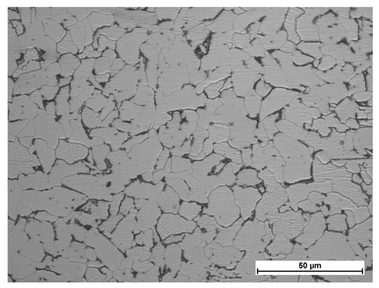
Figure 1.
Microstructure of the substrate of non-alloy steel S235JR (Magnification 500×), Table 1.
The composition of the metallic powder (not commercially available) for laser cladding was designed to provide high abrasive wear resistance and good corrosion resistance. Intentionally, the amount of strong carbide-forming elements such Cr, W, and V was high enough to ensure the in situ precipitation of fine dispersive carbides during laser cladding, as shown in Table 2. The particle size distribution of the metallic Fe-based powder was 53–150 µm.

Table 2.
Nominal composition of Fe-based experimental powder (wt. %).
In order to conduct the technological tests of cladding at cryogenic conditions, a prototype stand was designed and custom made, as shown in Figure 2a. The powder was dosed by a disc rotary feeder PFU4 (Durum, Willich, Germany) in argon carrying gas at the pressure of 1.5 bar and the rate flow of 8.0 L/min. Powder was gravity transported from a disc feeder to the nozzles head through flexible PTFE tubes (Polytetrafluoroethylene—“Teflon”) with an inner diameter of 2.0 mm each. Three individual and cylindrical nozzles of 0.8 mm diameter for powder injection were mounted on the head, as shown in Figure 2a. The powder injection nozzles were adjustable and set in such a way to focus the three individual powder streams on the top surface of the melt pool in the region of laser beam interaction, as shown in Figure 2b. The nozzles had was integrated with the laser focusing head coupled by a fiberglass with the IPG YLS laser generator (IPG Photonics, Oxford, MA, USA), emitting at the wavelength of 1.07 µm. The positioning of the laser focusing head with coaxial powder injection nozzles was provided by a robot Panasonic GII TL-190 (Industrial Solutions Company, Panasonic Corporation, Osaka, Japan). The beam parameter product (BPP) of the laser beam is <4.0 mm·mrad, and it is characterized by a Gaussian energy distribution across the beam spot (Transverse Electromagnetic Mode; TEM00). With the applied configuration of the optics, the nominal beam spot diameter was 300 μm, which is typical for laser welding. In the case of laser cladding, a wider beam is advantageous; therefore, the laser beam was defocused by lifting the laser head. Thus, the focal plane was 30.0 mm over the top surface of the substrate (focal spot position +30 mm), which resulted in increasing the diameter of the region of laser beam irradiation on the substrate up to 1.3 mm. Prior to cladding tests, the steel substrate was sandblasted, providing repeatable surface conditions with the roughness of Ra 25–60 μm, after which it was cleaned by ethanol C2H5OH.
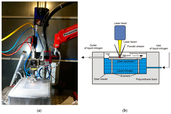
Figure 2.
(a) A view of the laser powder deposition process under cryogenic conditions on the experimental stand for technological tests of laser cladding and powder deposition equipped with a six-axis robot, an high power fiber laser (HPFL), powder dosing, and a delivery system with a specially designed powder head with three individual adjustable nozzles and a bath of liquid nitrogen for cooling the substrate; (b) a scheme for the laser powder deposition of a steel specimen immersed in a liquid nitrogen bath.
The stringer beads were 40.0 mm long, while the shift between individual beads was 10.0 mm. The range of the processing parameters was determined during preliminary tests, and the laser out power ranged between 250 and 1000 W, while the scanning speed ranged between 250 and 1000 mm/min, (Table 3, Figure 3). The powder feeding rate was kept constant at 6.0 g/min. Sixteen stringer beads were produced at different processing parameters on each substrate specimen, as shown in Figure 3. One specimen was laser cladded at free cooling in ambient air at the temperature of approximately 22 °C (conventional laser cladding). Meanwhile, the second specimen was partially immersed (approximately half the specimen thickness) in the bath of liquid nitrogen at the temperature of −190 °C to provide cryogenic conditions for cooling the substrate, as shown in Figure 2a,b. The liquid nitrogen bath was thermally isolated by polyurethane foam 15.0 mm thick placed on the bottom and side walls. As can be seen in Figure 2a, the liquid nitrogen was evaporating intensively during cladding; therefore, the gaseous nitrogen was present also in the region of powder deposition. Since the nitrogen is active gas, it acts as an alloying medium during laser powder deposition. Considering the above, the process of laser deposition of the powder can be defined as a hybrid process, combining conventional laser cladding and alloying or gas nitriding, which was additionally conducted under cryogenic conditions.

Table 3.
Parameters of laser deposition of experimental Fe-based metallic powder at free cooling conditions (conventional laser cladding) and forced cooling by liquid nitrogen bath under cryogenic conditions (hybrid laser deposition process), as shown in Figure 3.
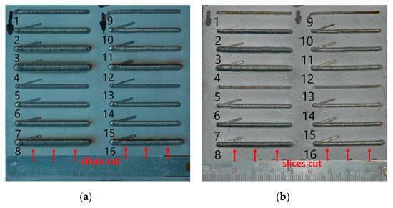
Figure 3.
A view of stringer beads produced by the laser deposition of experimental Fe-based metallic powder at (a) free cooling conditions (conventional laser cladding); (b) and forced cooling by liquid nitrogen bath under cryogenic conditions (hybrid laser deposition process), as shown in Table 3.
After completing the laser cladding tests, the first visual inspection was done. Next, the cross-sections were cut, and samples for metallographic study were prepared. Three sliced sections for every individual tested clad layer were take—one from the middle region of a bead, and two other at the distance 10.0 mm from the ends, as shown in Figure 3. A standard metallographic procedure for preparing the samples was applied.
The sections were mounted in thermosetting phenol resin with graphite filler Electro-WEM (Metalogis, Warsaw, Poland), next wet grinded by papers with the grit 120 to 2500, polished with 1 µm diamond suspension Metkon Diapat-M (Metkon Instruments Inc., Bursa, Turkey), and finally etched by the HNO3 + 3HCL reagent. Metallographic tests and analysis were carried out by means of stereoscopic microscope OLYMPUS SZX9 (Olumpus Corporation, Tokyo, Japan), the inverted metallographic microscope NIKON Eclipse MA100 (Nikon Corporation, Tokyo, Japan), and scanning electron microscope (SEM) (Carl Zeiss, Oberkochen, Germany), which were equipped with the energy-dispersive spectrometer (EDS) (Oxford Instruments, Abingdon, UK) and X-Ray diffractometer (Panalitycal, Almelo, The Netherlands), with CuKα source of radiation, and the 2θ angle range of 0 to 140°.
Hardness measurements were carried out on the cross-sections along the axis of symmetry of the individual bead, starting from under the top surface region (presented also in Figure 10). The measurements were carried out by means of the hardness tester WILSON WOLPERT 401 MVD (Wolpert Wilson Instruments, Aachen, Germany) at the load of 10 N and the dwell time of 10 s. The distance between the subsequent points was 0.3 mm.
3. Results and Discussion
3.1. Macro Observations and Single Bead Geometry
In order to determine the effect of the proposed novel technique of laser cladding of Fe-based powder combined with nitriding and forced cooling the substrate at cryogenic conditions, the comparative study of the clad layers produced at conventional laser cladding, and also at the so-called “hybrid” cryogenic laser deposition, are presented below. The geometry of a single bead was determined on cross-sections by measuring the penetration depth, width, and height of a bead; the area of the fusion zone; and the total area of the clad, as shown in Figure 4. All the tested clad layers were free of cracks; however, single pores with a small diameter below 0.1 mm can be observed on the cross-sections of layers produced both during free cooling and cryogenic conditions. Thus, no relationship was found between the conditions of cooling and tendency to porosity, as shown in Figure 5, Figure 6, Figure 7 and Figure 8.

Figure 4.
An example of the measuring procedure for determining the characteristic geometry features and dimensions of the stringer beads (Table 4): (a) measuring of the bead dimensions; (b) determination of the heat-affected zone (HAZ) area; (c) determination of the total area of the clad layer (fusion zone + clad layer).
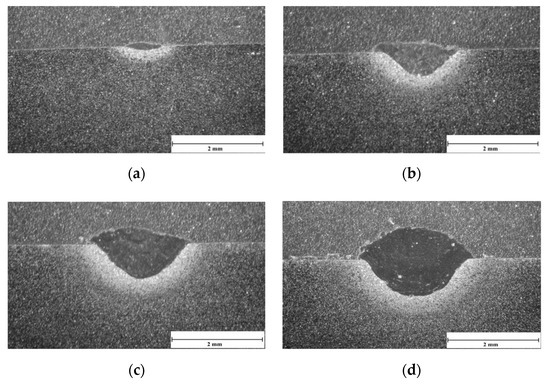
Figure 5.
Macrostructure and the single bead geometry of the clad layers produced by laser cladding of Fe-based powder on steel substrate at free cooling, constant scanning speed 250 mm/min, and different laser output power, Table 3 and Table 4: (a) LC1, 250 W; (b) LC2, 500 W; (c) LC3, 750 W; (d) LC4, 1000 W.
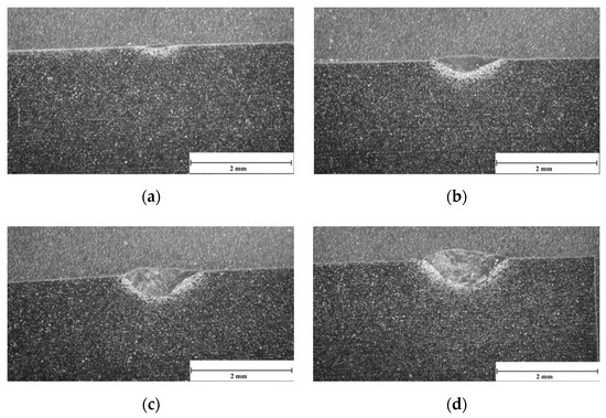
Figure 6.
Macrostructure and the single bead geometry of the clad layers produced by laser cladding of Fe-based powder on steel substrate at free cooling, constant scanning speed 1000 mm/min, and different laser output power, as shown in Table 3 and Table 4: (a) LC13, 250 W; (b) LC14, 500 W; (c) LC15, 750 W; (d) LC16, 1000 W.
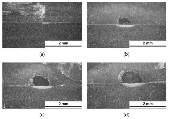
Figure 7.
Macrostructure and the single bead geometry of the clad layers produced by laser deposition of Fe-based powder on steel substrate at forced cooling by a liquid nitrogen bath under cryogenic conditions (hybrid laser deposition process), a constant scanning speed of 250 mm/min, and different laser output power, as shown in Table 3 and Table 4: (a) HC1, 250 W; (b) HC2, 500 W; (c) HC3, 750 W; (d) HC4, 1000 W.
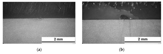
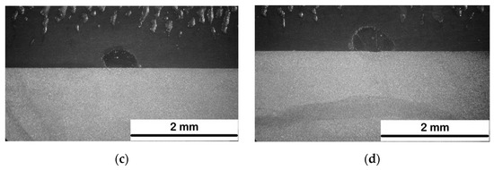
Figure 8.
Macrostructure and the single bead geometry of the clad layers produced by laser deposition of Fe-based powder on steel substrate at forced cooling by liquid nitrogen bath under cryogenic conditions (hybrid laser deposition process), constant scanning speed 500 mm/min, and different laser output power, as shown in Table 3 and Table 4: (a) HC5, 250 W; (b) HC6, 500 W; (c) HC7, 750 W; (d) HC8, 1000 W.
The representative cross-sections of test clad layers produced by conventional laser cladding at free cooling conditions are presented in Figure 5 and Figure 6, while the clad layers produced under cryogenic conditions are presented in Figure 7 and Figure 8. It is worth noting that three cross-sections were analyzed for every individual bead. Since the total number of analyzed cross-sections is huge, just the selected representative sections are presented in the following figures. The results of geometry measurements for induvial beads are summarized in Table 4, Figure 9. The given results are the mean values with standard deviation taken from the analysis of three individual sections for every single bead. The value of dilution “D” was calculated by the following formula:
where AFZ is the cross-section area of the fusion zone, and the ACL is the cross-section area of the clad layer (presented also in Figure 10).

Table 4.
Results of geometry determined for the stringer beads produced by the laser deposition of experimental Fe-based metallic powder at free cooling conditions (conventional laser cladding) and forced cooling by liquid nitrogen bath under cryogenic conditions (hybrid laser deposition process), as shown in Figure 5, Figure 6, Figure 7 and Figure 8.
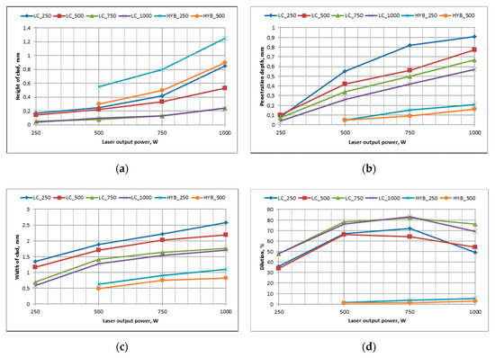
Figure 9.
Influence of the process parameters and cooling conditions on the geometry and dimensions of the stringer beads produced by laser deposition of Fe-based powder (Table 3 and Table 4): (a) height of the clad (reinforcement); (b) penetration depth into the substrate; (c) width of the single clad layer; and (d) calculated rate of dilution.
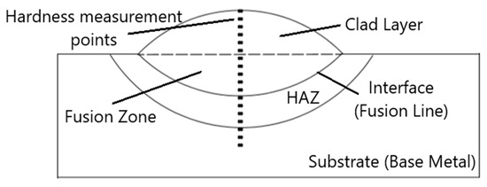
Figure 10.
Scheme of hardness measurements and characteristic features of single bead geometry, as shown in Figure 11.
The relationship between process parameters, cooling conditions, and the geometry of single beads is summarized in Figure 9. Due to the large number of curves presented on the individual graphs, and relatively low standard deviation, it was decided to provide the statistical results just in tabular form in Table 4. Presenting the standard deviation for each point on the graphs would make it completely illegible.
As can be seen, the clad layers produced by laser cladding at free cooling conditions are characterized by a clear fusion line (also called the “interface line”), indicating complete fusion across the layer, and proper metallurgical bonding in a whole range of processing parameters. It is also obvious that the shape and dimensions of the single bead depends on processing parameters; however, the penetration depth is relatively high compared to the height of the test beads, resulting in high dilution ranged from approximately 34% to over 80%, as shown in Table 4 and Figure 5, Figure 6 and Figure 9. Contrary, in the case of the test clad layers produced at cryogenic conditions, the geometry is completely different, as shown in Figure 7 and Figure 8. The clad layers produced in the lowest range of energy input at a scanning speed of over 500 mm/min were characterized by incomplete fusion along the stringer beads, which was revealed during preparation of the metallographic samples. Therefore, the layers were not taken into further study.
As can be seen in Figure 7 and Figure 8, the penetration depth is typically very small on the verge of lack of fusion. Low penetration depth resulted in very low dilution ranging from 1.1% to 5.2%, as shown in Table 4 and Figure 9. Low dilution is beneficial because it provides the chemical composition of the deposited layer similar to the original composition of the powder. Moreover, the analyzed single beads showed greater height, at the same time with a smaller width, compared to the beads produced at the same processing parameters but under free cooling conditions.
This phenomenon, as well as the low penetration depth, is related with the supercooled substrate immersed in the bath of liquid nitrogen at temperature—190 °C. Under such conditions, the supercooled substrate dissipates the absorbed laser energy, limiting the penetration ability of the laser beam. At the same time, powder particles fed into the region of laser beam interaction are heated, melted, and deposited on the substrate. Moreover, conditions for wetting the slightly melted substrate at obviously lower temperature are not favorable, resulting in trends for shaping a spherical cross-section of the single bead, as shown in Figure 7 and Figure 8. Therefore, the single beads produced at cryogenic conditions are characterized by small width and relatively large height compared to the beads produced at free cooling conditions, as shown in Figure 9.
The above findings indicate that a controllable forced cooling of the substrate during laser cladding can be considered as an auxiliary technique for shaping the geometry of clad layers and minimizing the dilution of the deposit by the substrate material. Providing low dilution is especially of importance during the manufacturing of single layer, thin coatings on the substrate that significantly differ in chemical composition from the coating material.
3.2. Microhardness
The profiles of hardness were determined on a cross-section of the chosen representative clad layers as demonstrated in Figure 10. The profiles of Vickers HV1 hardness presented in Figure 11 showed distinct difference in the measured maximum hardness values for the clads produced at free cooling conditions and the clads produced by the novel technique of laser deposition of powder under cryogenic conditions in a liquid nitrogen bath. Additionally, the shape (distribution) of the hardness HV1 profiles is different, as can be seen in Figure 11. The presented results of hardness measurement for each point on the graphs are a mean value taken from three different sections for every tested clad layer (single bead). As can be seen, the low values of standard deviation indicate a small dispersion of results. This is due to the relatively large size of the Vickers’s indenter imprint at the load of 10N, but also the homogeneity of the macrostructure, as can be seen in Figure 5, Figure 6, Figure 7 and Figure 8.
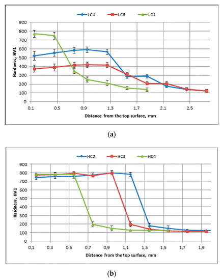
Figure 11.
Hardness distribution on cross-sections of the representative stringer beads produced by the laser deposition of experimental Fe-based metallic powder (Table 3, Figure 10): (a) at free cooling conditions (conventional laser cladding); and (b) at forced cooling by liquid nitrogen bath under cryogenic conditions (hybrid laser deposition process).
In a case of the tested clad layers produced by conventional laser cladding at free cooling, the hardness reaches the maximum in the clad region, but the spread of the values differs distinctly for the individual clads (750–780 HV1 for LC1, 520–590 HV1 for LC4, and 370–420 HV1 for LC8), indicating the significant influence of processing parameters on the hardness, as shown in Figure 11a. The differences in the hardness values of the individual layers are related to the dilution degree. As can be seen in Figure 11a, the maximum hardness value (780HV1) was measured for the clad layer characterized by the lowest dilution 36%, as shown in Figure 9d and Table 4. In turn, the higher the dilution degree (49% for LC4 and 54% for LC8), the lower the hardness in the clad region, as shown in Figure 11a and Table 4. Since the final composition of the clad layer is the effect of mixing the deposited powder and melted substrate, the increasing penetration depth leads to deterioration of the originally designed composition of the powder. In this study, the clad layers are diluted mainly by Fe, which comes from the non-alloy steel substrate, as shown in Table 1 and Table 4.
At a certain depth related to the clad thickness (both the clad height and penetration depth), the hardness decreases gradually until reaching the value of the base metal (S235JR) of the substrate at approximately 120–130 HV1. The gradual decrease in hardness occurs in the heat-affected zone (HAZ). Based on the hardness distribution in the HAZ, the width of this region can be specified at 0.8 to 1.3 mm for the tested clads. It can be also verified on the cross-sections in Figure 5 and Figure 6. Since the fusion line is considered as an interface line for a coating, and the HAZ is considered as the interface region, it can be concluded that in the case of clad layers produced by conventional laser cladding at free cooling, the interface region is “wide and smooth”.
On the other hand, the profiles of hardness determined on the cross-sections of the clad layers produced under cryogenic conditions are almost flat in the clad region, while the maximum hardness value for the individual layers is in the same range between 740 and 800 HV1, as shown in Figure 11b. The hardness profile drops down sharply to approximately 200 HV1 when reaching the fusion line (interface line). As can be seen in Figure 11b, the region of the HAZ is very narrow, because the hardness of the base metal (S235JR) is reached after less than 0.5 mm. So, in this case, it can be concluded that the interface region of clad layers produced under cryogenic conditions is “narrow and sharp”. This phenomenon is a result of extremely low dilution below 5% and also a very narrow HAZ due to initial super cooling the substrate in the bath of liquid nitrogen, as well as rapid heat dissipation during the laser deposition of the powder.
3.3. Microstructure and Phase Composition
The X-ray diffraction patterns of two comparative samples and the steel substrate are presented in Figure 12. The comparative samples were prepared especially for XRD analysis by multi-bead cladding of the substrate with an overlap of approximately 25% to produce the coating 6.0–7.0 mm wide for providing reliable conditions for the analysis, since the beam diameter in the applied apparatus is nominally 4 mm and can be additionally focused to 1–2 mm. The parameters providing the widest single beads produced by laser cladding both at free cooling and under cryogenic conditions were selected (CL4 and HC4, Table 3), as shown in Figure 13. Next, the surfaces were grinded to provide roughness Ra of 0.8–1.1 μm.
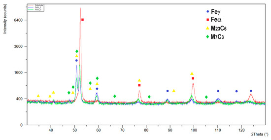
Figure 12.
XRD patterns of the substrate of non-alloy steel S235JR and comparative coatings produced as multi-bead cladding at the processing parameters for LC4 and HC4 (scanning speed 250 mm/min, laser output power 1000 W, energy input 240 J/mm, free cooling and forced cooling respectively, Table 3).
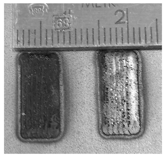
Figure 13.
A view of specimens prepared for XRD analysis (from left: HC4 and CL4; see Table 3).
The X-ray diffraction pattern of the substrate (“substrate” red line in Figure 12) indicated dominant peaks from Fe-α, which is typical for non-alloy steel. In the case of the X-ray diffraction patterns of the tested coatings, the dominant peaks come from Fe-α and Fe-γ. However, clear differences can be observed in the patterns. Intensity of the Fe-α peaks is significantly higher in the case of the coating produced by laser cladding at free cooling conditions, indicating a higher share of the Fe-α in this case (“FeCr_3” green line in Figure 12). It is related both with the different degree of dilution and different cooling and solidification rates. The degree of dilution for the clad layer HC4 produced under cryogenic conditions is approximately just 5% and almost 10 times higher (approximately 49%) in the case of the clad layer LC4 produced by conventional laser cladding at free cooling conditions, as shown in Table 4. Therefore, the coating produced under cryogenic conditions is slightly influenced by the composition of the substrate of non-alloy steel, while the coating produced at free cooling is composed just of half of the powder and half of the base metal substrate. However, what is decisive for the share of Fe-α and Fe-γ is the cooling rate, which is significantly higher in the case of cryogenic conditions. An extremely high cooling rate inhibits the martensitic transformation. Therefore, the share of retained austenite is higher in the clad layer produced under cryogenic conditions (“FeCr_1” blue line in Figure 12), despite the high content of ferrite-stabilizing elements such Mo, V, W, and Cr, as shown in Table 2. Other peaks from the X-ray diffraction patterns correspond mainly with carbides M23C6 and M7C3, as shown in Figure 12. The detection level of the applied XRD method is about 3% for the specific phase; therefore, it doesn’t allow for precise identification of the fine precipitations at a low share. However, due to the composition containing W, V, and Cr, complex carbides are most expected.
Typical microstructures of the clad layers produced at a scanning speed of 250 mm/min and laser output power of 1000 W both at free cooling and under cryogenic conditions are presented on optical micrographs in Figure 14. Figure 14a,b show the overall microstructure in the fusion line (interface) region at the same magnification: 200x. Meanwhile, Figure 14c,d show the typical microstructure in the middle region of the clad layers at the same magnification: 500×. As can be seen, there is a clear difference in grain size. The substrate of non-alloy steel S235JR after hot rolling originally exhibits a ferritic microstructure with pearlitic regions along the grain boundaries, as shown in Figure 1. In the case of the analyzed surface layer (LC4) produced at free cooling, the region adjacent to the fusion line (interface) exhibits a microstructure of upper bainite, as shown in Figure 14b. In turn, the same region in the case of the surface layer produced under cryogenic conditions (HC4) can be identified as martensite microstructure, as shown in Figure 14a. The micrographs of the representative clad layers are free of cracks or pores. Close observation of the fusion zone (clad region) revealed the layer of planar crystallisation with a thickness of approximately 5 µm in the case of the clad layer produced at free cooling (LC4), which was three times narrower in the case of the layer produced under cryogenic conditions (HC4), as shown in Figure 14a,b. Above the planar crystals zone, the columnar dendrites can be observed with interdendritic regions. Next, in the middle region of the clad layers (fusion zone), the presence of equiaxed dendrites and cellular crystals was confirmed, as shown in Figure 14c,d. Such columnar dendrites adjacent to the interface indicate a very high G/R ratio in this region during solidification, where G is the temperature gradient, and R is the solidification rate. As the distance from the interface (fusion line) increases, the G/R ratio decreases, and equiaxed dendrites growth take place. On the other hand, the solidification rate affects the grain size, and it is related with the secondary dendrite arm spacing (SDAS). Based on the optical micrographs, the mean SDAS for the middle region of the clad layers was calculated by dividing the measuring length on the columnar dendrite by the number of dendrite arms, as shown in Table 5. The mean SDAS for the clad layer produced at free cooling was 3.1 µm, while the SADS for the clad produced at the same processing parameters but forced cooling in liquid nitrogen bath was 1.28 µm, indicating a significant difference in the cooling and solidification rates. The fine-grained microstructure is preferred because according to the relationship of Hall–Petch, the lower grain size increases the microhardness and also increases the wear resistance. Moreover, the optical micrographs show dispersive dots that are mainly in the interdendritic regions, which most likely are precipitations of complex carbides, as shown in Figure 14c,d.
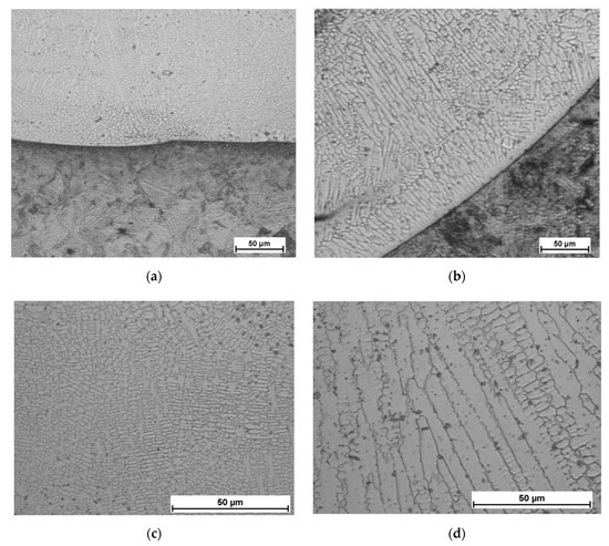
Figure 14.
Microstructure of the comparative stringer beads LC4 and HC4 produced at the same process parameters (scanning speed 250 mm/min, laser output power 1000 W, energy input 240 J/mm) but different cooling conditions (Table 3 and Table 5): (a,c) forced cooling under cryogenic conditions in a liquid nitrogen bath—interface region and middle region of the clad, respectively; and (b,d) free cooling in ambient air—interface region and middle region of the clad, respectively.

Table 5.
Results of determination of the secondary dendrite arm spacing (SDAS) for the comparative stringer beads LC4 and HC4 produced at the same process parameters (scanning speed 250 mm/min, laser output power 1000 W, energy input 240 J/mm) but different cooling conditions (Table 3, Figure 14c,d).
To more accurately determine the microstructure, SEM micrographs at high magnification were analyzed. The following is an example of the microstructure for the clad layer HC4 produced under cryogenic conditions. As can be seen in Figure 15, the typical very fine martensitic microstructure with clear retained austenite was disclosed within the dendritic areas, while highly dispersed nanometric-sized (200–360 nm) precipitations can be found in the interdendritic regions. Further EDS analysis indicated that the nanometric-sized precipitations are composed of tungsten, molybdenum vanadium, chromium, and iron, as shown in Figure 16. These results of SEM and EDS analysis clearly indicate that the dendritic grains are composed of solid solution based on Fe (Figure 16a,c), while the interdendritic regions are most likely composed of eutectic and precipitations of fine complex carbides (Figure 16a,b), which were identified by XRD analysis as M23C6 and M7C3, as shown in Figure 12.
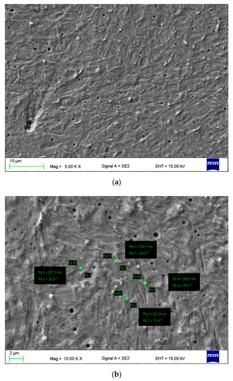
Figure 15.
SEM micrograph in the middle region of the clad of stringer bead HC4 produced by the laser deposition of Fe-based powder (scanning speed 250 mm/min, laser output power 1000 W, energy input 240 J/mm) at forced cooling under cryogenic conditions in a liquid nitrogen bath (Table 3, Figure 12 and Figure 16): (a) an overview of the microstructure within the dendritic regions (typical martensitic morphology); and (b) a close view of precipitations in interdendritic regions with measuring the dimensions (201.9–356.8 nm).
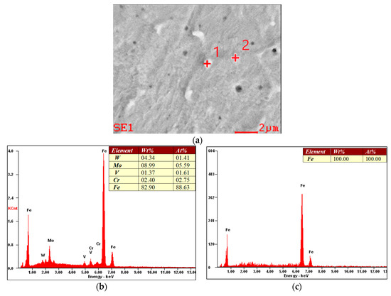
Figure 16.
SEM micrograph (a) of the middle region of the clad of stringer bead HC4 (Table 3) chosen for energy-dispersive spectrometer (EDS) analysis: (b) EDS spectrum of the precipitation (a white dot in point No. 1); (c) EDS spectrum of the dendrite area (a gray region below point No. 2).
4. Conclusions
The novel technique of laser deposition of Fe-based powder under cryogenic conditions provided by the liquid nitrogen bath was successfully demonstrated. Due to intensive evaporation of the liquid nitrogen and the presence of nitrogen vapors in the melt pool region, the proposed technique can be considered as a hybrid process combining laser powder deposition (conventional laser cladding) with laser alloying by the gaseous nitrogen (precisely, laser gas nitriding—LGN).
The results of the study indicate that due to the supercooled substrate, which dissipates the absorbed laser energy, the penetration depth, width of HAZ, as well as the dilution (49% for cladding at free cooling and 5.2% under cryogenic conditions for comparative samples LC4 and HC4) can be significantly reduced. Such low rates of dilution provide beneficial profiles of hardness, uniform distribution in the clad layer with highest values of hardness (740–800 HV1 for clad layers produced under cryogenic conditions, and 370–780 HV1 for clad layers produced at free cooling).
Moreover, the test stringer beads produced under cryogenic conditions tend to increase in height and decrease in width, which can especially beneficial in the case of single-layer coatings of different composition than the substrate. Therefore, the technique of forced cooling can be useful for shaping the geometry of the clad layers. It was also found that forced cooling under cryogenic conditions has a beneficial effect on the refinement of the microstructure of the clad layers produced by the Fe-based powder, which was quantitatively determined by measuring the secondary dendrite arm spacing (SADS 3.1 µm for LC4 and 1.28 µm for HC4).
The above features such as the high hardness, homogeneity, and refinement of the microstructure may have also a beneficial effect on the tribological properties of coatings produced under forced cooling. However, further comprehensive stud related to the influence of forced cooling on thermal cycles, cooling, and solidification rates, as well as the wear characteristic of coatings under different load, is necessary.
Author Contributions
Conceptualization, methodology, investigation, formal analysis, validation, supervision, writing—review and editing, A.L.; project administration, funding acquisition, D.Ś. All authors have read and agreed to the published version of the manuscript.
Funding
The research was supported by the National Centre for Research and Development, Poland, under the grant number POIR.01.01.01-00-0278/15-007-02, financed by EU funds.
Acknowledgments
The authors thank all those who assisted in the preparation of samples and the conducting of measurements for their technical support, especially to Marcin Żuk, Adrian Kukofka, and their students who assisted in the laboratory tests.
Conflicts of Interest
The authors declare no conflict of interest.
References
- Kusinski, J.; Kąc, S.; Kopia, A.; Radziszewska, A.; Rozmus-Górnikowska, M.; Major, B.; Major, L.; Marczak, J.; Lisiecki, A. Laser modification of the materials surface layer—A review paper. Bull. Pol. Acad. Sci. Tech. Sci. 2012, 60, 711–728. [Google Scholar] [CrossRef]
- Gopinath, M.; Thota, P.; Kumar, A. Role of molten pool thermo cycle in laser surface alloying of AISI 1020 steel with in-situ synthesized TiN. Surf. Coat. Technol. 2019, 362, 150–166. [Google Scholar] [CrossRef]
- Lisiecki, A. Mechanisms of hardness increase for composite surface layers during laser gas nitriding of the Ti6A14V alloy. Mater. Technol. 2017, 51, 577–583. [Google Scholar]
- Kik, T.; Górka, J. Numerical simulations of laser and hybrid S700MC T-joint welding. Materials 2019, 12, 516. [Google Scholar] [CrossRef] [PubMed]
- Lisiecki, A. Welding of titanium alloy by different types of lasers. Arch. Mater. Sci. Eng. 2012, 58, 209–218. [Google Scholar]
- Lisiecki, A.; Kurc-Lisiecka, A. Erosion wear resistance of titanium-matrix composite Ti/TiN produced by diode-laser gas nitriding. Mater. Teh. 2017, 51, 29–34. [Google Scholar] [CrossRef]
- Zhao, X.; Zhang, P.; Wang, X.; Chen, Y.; Liu, H.; Chen, L.; Sheng, Y.; Li, W. In-situ formation of textured TiN coatings on biomedical titanium alloy by laser irradiation. J. Mech. Behav. Biomed. 2018, 78, 143–153. [Google Scholar] [CrossRef]
- Kurc-Lisiecka, A.; Lisiecki, A. Laser welding of new grade of advanced high strength steel Domex 960. Mater. Teh. 2017, 51, 199–204. [Google Scholar] [CrossRef]
- Lisiecki, A. Titanium matrix composite Ti/TiN produced by diode laser gas nitriding. Metals 2015, 5, 54–69. [Google Scholar] [CrossRef]
- Lisiecki, A. Study of optical properties of surface layers produced by laser surface melting and laser surface nitriding of titanium alloy. Materials 2019, 12, 3112. [Google Scholar] [CrossRef]
- Kaźmierczak-Bałata, A.; Mazur, J. Effect of carbon nanoparticle reinforcement on mechanical and thermal properties of silicon carbide ceramics. Ceram. Int. 2018, 44, 10273–10280. [Google Scholar] [CrossRef]
- Lisiecki, A.; Piwnik, J. Tribological characteristic of titanium alloy surface layers produced by diode laser gas nitriding. Arch. Met. Mater. 2016, 61, 543–552. [Google Scholar] [CrossRef]
- Yang, C.; Liu, J. Intermittent vacuum gas nitriding of TB8 titanium alloy. Vacuum 2019, 163, 52–58. [Google Scholar] [CrossRef]
- Wolowiec-Korecka, E.; Michalski, J.; Kucharska, B. Kinetic aspects of low-pressure nitriding process. Vacuum 2018, 155, 292–299. [Google Scholar] [CrossRef]
- Lisiecki, A.; Burdzik, R.; Siwiec, G.; Konieczny, Ł.; Warczek, J.; Folęga, P.; Oleksiak, B. Disk laser welding of car body zinc coated steel sheets. Arch. Met. Mater. 2015, 60, 2913–2922. [Google Scholar] [CrossRef]
- Pakieła, W.; Tański, T.; Pawlyta, M.; Brytan, Z.; Sroka, M. The structure and mechanical properties of AlMg5Si2Mn alloy after surface alloying by the use of fiber laser. Appl. Phys. A 2018, 124, 263. [Google Scholar] [CrossRef]
- Bonek, M. The investigation of microstructures and properties of high speed steel HS6-5-2-5 after laser alloying. Arch. Metall. Mater. 2014, 59, 1647–1651. [Google Scholar] [CrossRef]
- Tomków, J.; Rogalski, G.; Fydrych, D.; Łabanowski, J. Advantages of the application of the temper bead welding technique during wet welding. Materials 2019, 12, 915. [Google Scholar] [CrossRef]
- Moskal, G.; Grabowski, A.; Lisiecki, A. Laser remelting of silicide coatings on Mo and TZM alloy. Solid State Phenom. 2015, 226, 121–126. [Google Scholar] [CrossRef]
- Janicki, D. Microstructure and sliding wear behaviour of in-situ TiC-reinforced composite surface layers fabricated on ductile cast iron by laser alloying. Materials 2018, 11, 75. [Google Scholar] [CrossRef]
- Lisiecki, A. Comparison of titanium metal matrix composite surface layers produced during laser gas nitriding of Ti6Al4V alloy by different types of lasers. Arch. Met. Mater. 2016, 61, 1777–1784. [Google Scholar] [CrossRef]
- Li, C.; Zhang, Q.; Wang, F.; Deng, P.; Lu, Q.; Zhang, Y.; Li, S.; Ma, P.; Li, W.; Wang, Y. Microstructure and wear behaviors of WC-Ni coatings fabricated by laser cladding under high frequency micro-vibration. Appl. Surf. Sci. 2019, 485, 513–519. [Google Scholar] [CrossRef]
- Lisiecki, A.; Ślizak, D.; Kukofka, A. Robotic fiber laser cladding of steel substrate with iron-based metallic powder. Mater. Perform. Charact. 2019, 8, 1202–1213. [Google Scholar] [CrossRef]
- Górka, J.; Czupryński, A.; Żuk, M.; Adamiak, M.; Kopyść, A. Properties and structure of deposited nanocrystalline coatings in relation to selected construction materials resistant to abrasive wear. Materials 2018, 11, 1184. [Google Scholar] [CrossRef]
- Lukaszkowicz, K.; Jonda, E.; Sondor, J.; Balin, K.; Kubacki, J. Characteristics of the AlTiCrN+DLC coating deposited with a cathodic arc and the PACVD process. Mater. Teh. 2016, 50, 175–181. [Google Scholar] [CrossRef]
- Klimpel, A.; Dobrzański, L.A.; Lisiecki, A.; Janicki, D. The study of properties of Ni-WC wires surfaced deposits. J. Mater. Process. Technol. 2005, 164–165, 1046–1055. [Google Scholar] [CrossRef]
- Ji, X.; Qing, Q.; Ji, C.; Cheng, J.; Zhang, Y. Slurry erosion wear resistance and impact-induced phase transformation of titanium alloys. Tribol. Lett. 2018, 66, 64. [Google Scholar] [CrossRef]
- Li, S.; Li, C.; Deng, P.; Zhang, Y.; Zhang, Q.; Sun, S.; Yan, H.; Ma, P.; Wang, Y. Microstructure and properties of laser-cladded bimodal composite coatings derived by composition design. J. Alloys Compd. 2018, 745, 483–489. [Google Scholar] [CrossRef]
- Klimpel, A.; Dobrzański, L.A.; Lisiecki, A.; Janicki, D. The study of the technology of laser and plasma surfacing of engine valves face made of X40CrSiMo10-2 steel using cobalt-based powders. J. Mater. Process. Technol. 2006, 175, 251–256. [Google Scholar] [CrossRef]
- Sadeghimeresht, E.; Markocsan, N.; Nylén, P. A comparative study of corrosion resistance for HVAF-sprayed Fe- and Co-based coatings. Coatings 2016, 6, 16. [Google Scholar] [CrossRef]
- Wang, H.; Zhang, S.; Zhang, C.; Wu, C.; Zhang, J.; Abdullah, A. Effects of V and Cr on laser cladded Fe-based coatings. Coatings 2018, 8, 107. [Google Scholar] [CrossRef]
- Zhu, H.; Li, Y.; Li, B.; Zhang, Z.; Qiu, C. Effects of low-temperature tempering on microstructure and properties of the laser-cladded AISI 420 martensitic stainless steel coating. Coatings 2018, 8, 451. [Google Scholar] [CrossRef]
- Chen, J.; Zhou, Y.; Shi, C.; Mao, D. Microscopic analysis and electrochemical behavior of Fe-based coating produced by laser cladding. Metals 2017, 7, 435. [Google Scholar] [CrossRef]
- Li, J.; Zhu, Z.; Peng, Y.; Shen, G. Effect of Carbon fiber addition on the microstructure and wear resistance of laser cladding composite coatings. Coatings 2019, 9, 684. [Google Scholar] [CrossRef]
- Hou, X.; Du, D.; Chang, B.; Ma, N. Influence of scanning speed on microstructure and properties of laser cladded Fe-based amorphous coatings. Materials 2019, 12, 1279. [Google Scholar] [CrossRef]
- Zhang, X.; Zhou, Y. Effect of deep cryogenic treatment on microstructure and wear resistance of LC3530 Fe-based laser cladding coating. Materials 2019, 12, 2400. [Google Scholar] [CrossRef] [PubMed]
- Zieliński, A.; Jażdżewska, M.; Naroźniak-Łuksza, A.; Serbiński, W. Surface structure and properties of Ti6Al4V alloy laser melted at cryogenic conditions. J. Achiev. Mater. Manuf. Eng. 2006, 18, 423–426. [Google Scholar]
- Zieliński, A.; Serbiński, W.; Majkowska, B.; Jażdżewska, M.; Skalski, I. Influence of laser remelting at cryogenic conditions on corrosion resistance of non-ferrous alloys. Adv. Mater. Sci. 2009, 9, 21–28. [Google Scholar] [CrossRef]
- Majkowska, B.; Serbiński, W. Cavitation wearing of the SUPERSTON alloy after laser treatment at cryogenic conditions. Solid State Phenom. 2010, 165, 306–309. [Google Scholar] [CrossRef]
- Cui, Z.; Shi, H.; Wang, W.; Xu, B. Laser surface melting AZ31B magnesium alloy with liquid nitrogen-assisted cooling. Trans. Nonferrous Met. Soc. China 2015, 25, 1446–1453. [Google Scholar] [CrossRef]
© 2020 by the authors. Licensee MDPI, Basel, Switzerland. This article is an open access article distributed under the terms and conditions of the Creative Commons Attribution (CC BY) license (http://creativecommons.org/licenses/by/4.0/).