Article

The Relationship between the Model of the Laser Biomimetic Strengthening of Gray Cast Iron and Matching between Different Brake Pads

1
College of Automotive Engineering, Jilin University, Changchun 130025, China
2
School of Mechanical Science and Aerospace Engineering, Jilin University, Changchun 130025, China
3
College of Material Science and Engineering, Jilin University, Changchun 130025, China
*
Author to whom correspondence should be addressed.
Metals 2020, 10(2), 184; https://doi.org/10.3390/met10020184
Submission received: 21 December 2019 / Revised: 20 January 2020 / Accepted: 23 January 2020 / Published: 27 January 2020
(This article belongs to the Special Issue Advanced Laser Processing of Alloys)

Abstract

:
When the surface of gray cast iron is subjected to laser irradiation and melted and then re-solidified, a material can be obtained that has a superior structure and properties to the base metal. On the surface of gray iron brake drums, the surface of the raw material can be processed into a bionic coupling surface with different shapes, structures, and soft and hard tissues similar to the surface of an organism. The wear resistance and fatigue resistance of brake drum surfaces can be greatly improved. However, the relative wear characteristics of the friction pairs in brake systems show that performance improvements in brake systems are the result of appropriately matching the brake drum and brake pad. This paper studies the wear relationship between three kinds of commonly-used brake pads (semi-metallic, organic asbestos-free, and ceramic) and different biomimetic models of brake drum samples. The interaction mechanism and failure mode between three kinds of brake pads and bionic samples were determined. According to the wear test results, the matching relationship between the brake pads and the brake drum was analyzed and determined, which provides a basis for the application of bionic brake drums.

1. Introduction

Due to their low cost, good thermal conductivity, and processability, gray iron brakes are widely used in truck braking systems [1]. Many effective methods have been proposed to strengthen the service life of cast-iron brake drums. Solutions from the perspective of material properties have included the use of steel brake drums [2], aluminum composite brake drums [3], and nodular cast iron or vermicular cast-iron brake drums [4,5,6]. From the structural aspects of brake drums, stiffeners for the outer wall have been developed to enhance the anti-deformation ability of the brake drum [7]. According to previous research, cast-iron brake drum technology is relatively comprehensive, and improvements and developments of cast iron brake drum materials are maturing. Compared with other novel brake drum materials, cast iron has a low manufacturing cost and good stability and is likely to continue to be the primary brake drum material for the foreseeable future.
There are currently three mainstream brake pads on the market. Semi-metallic brake pads currently dominate the domestic market and are mainly made of iron, copper, and other fibers or powders as reinforcement materials. Semi-metallic brake pads have high friction coefficients and are easy to process and form, and their outstanding thermal conductivity can reduce the wear temperature of friction pairs. Asbestos-free brake pads were first developed in the United States before being used globally. The Japanese brake industry developed a new type of ceramic brake pad in the last century, which is mainly composed of ceramic fibers, non-ferrous filler, adhesive, and a small amount of metal. It has the advantages of no noise, no falling ash, no hub corrosion, a long service life, and is environmentally friendly.
Over the course of billions of years of evolution, organisms have developed to survive by consuming the least amount of energy to obtain the greatest benefits, resulting in the formation of many excellent structural characteristics [8,9]. Inspired by biological performance, researchers have performed surface strengthening research on bionic truck brake drums. The results have shown that bionic coupling surfaces formed by combining a laser-melted area with a base metal area in brake drums effectively resisted thermal fatigue and inhibited crack initiation [10,11]. The performance of machined surfaces could be changed to some extent by machining the point, stripe, and grid biomimetic units on the surface of cast-iron brake drums [12,13]. Chen Zhikai et al. optimized the bionic coupling surface of gray cast iron, using a bionic model, by changing the characteristic parameters of the bionic unit and determined the influence of model parameters on the surface performance [14,15].
Bionic reinforcement surfaces produced by coupling bionics have good wear resistance and fatigue resistance on the inner wall of the brake drums. However, since brake systems are composed of a brake disc and a brake pad, the inclusion of a unilateral brake does not enhance the service life of the entire system. Thus, in this paper, starting from the relationship between friction and wear between the bionic brake hub and the brake pad, the matching between the bionic brake hub and the brake pad was studied. According to the research results, the bionic coupling model of the inner surface of the brake hub was redesigned to improve the performance of the whole bionic brake system.

2. Experimental

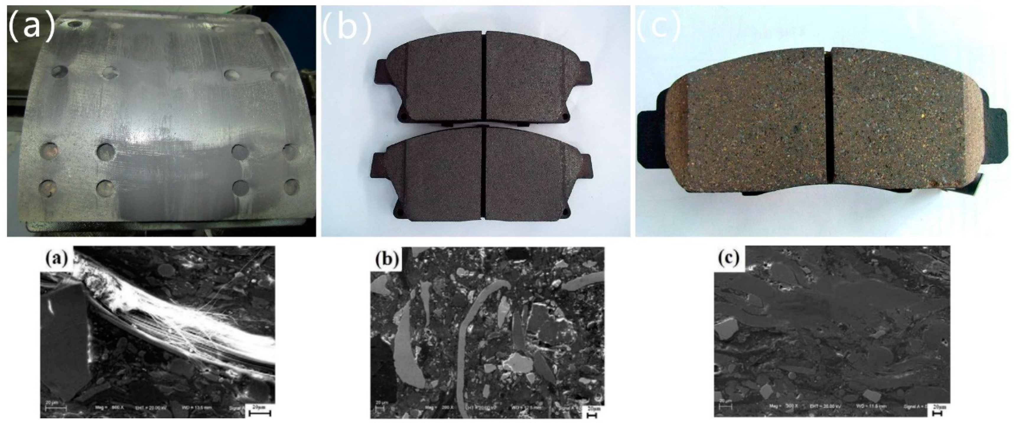
2.1. Experiment Materials

HT250 was used as the gray cast iron. The microstructure of the test material was flake graphite and pearlite, and the chemical composition of gray cast iron is given in Table 1. The material composition was determined by laser energy spectra. Figure 1 shows the three common commercially-used brake pad materials that were selected: semi-metallic, organic asbestos-free (NAO), and ceramic brake pads. Figure 1a shows that the semi-metallic brake pad surface contains obvious metal microstructures and fine filaments. Figure 1b shows that the NAO brake pad contains uniform fibers and a relatively flat surface. Figure 1c shows that the ceramic brake pad has fine ceramic particles. Additionally, Figure 1b,c show obvious brass particles, which were formed due to the poor thermal conductivity of NAO and ceramic brake pads due to material limitations. This easily caused a heat-induced recession, so brass was added to adjust the thermal conductivity.

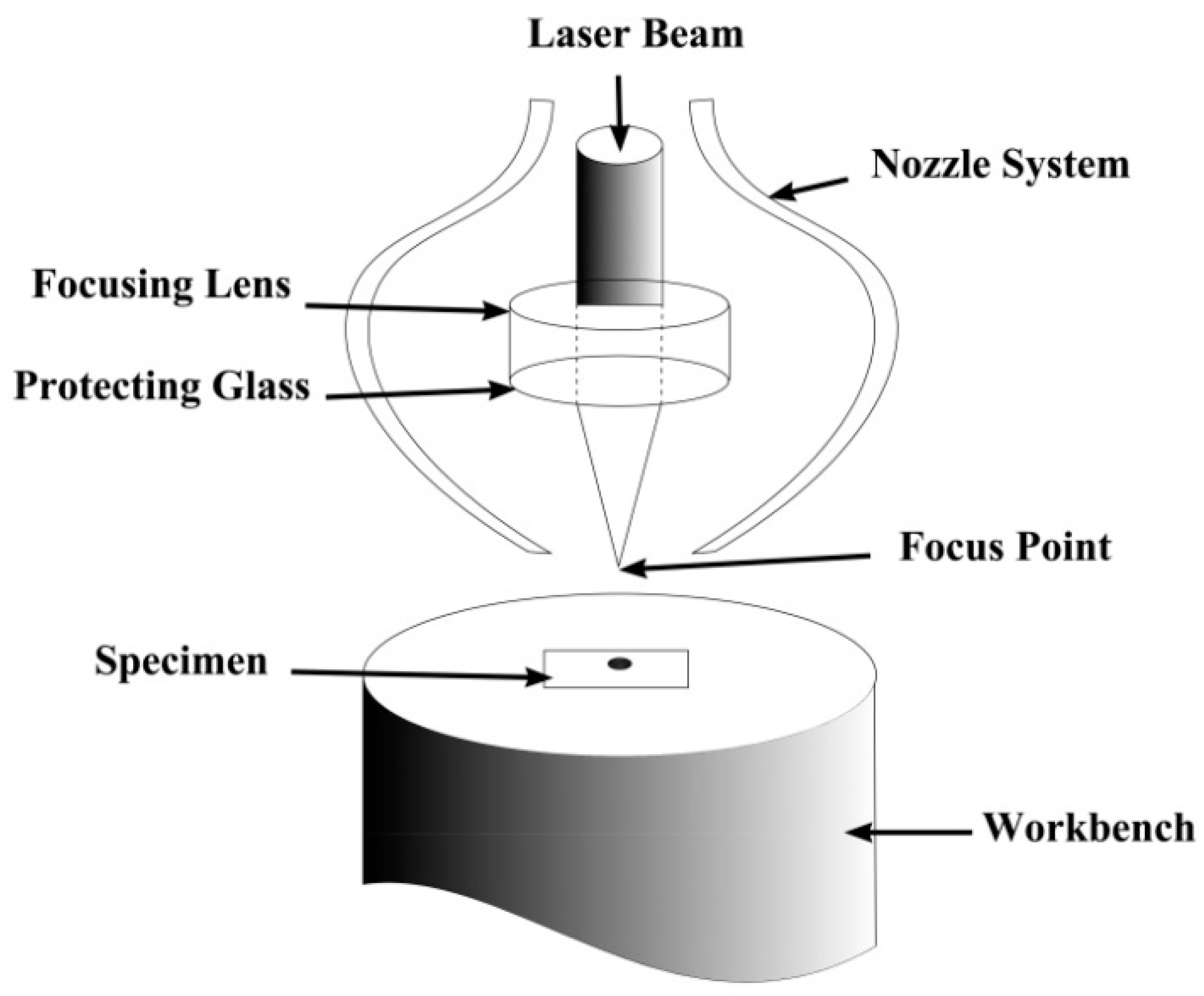
2.2. Experimental Method

The brake drum products of the FAW (First Automotive Works) casting company were used as the object, and the brake drum was destroyed to prepare the sample. Due to the excellent bionic coupling models reported in previous research, a coupling bionic model of the sample surface was designed and processed by laser melting [16,17]. First, the relationship between the different brake pads and the normal blank brake drum sample without any strengthening treatment, the wear form, and the failure mechanism were analyzed. Based on this, the wear relationship between different biomimetic coupling models and different kinds of brake pads were analyzed. The surface damage mechanism between the brake pad and the bionic model was analyzed based on the wear results and wear surface. According to the test results, the couple wear loss between the brake pad and the bionic model was summarized.

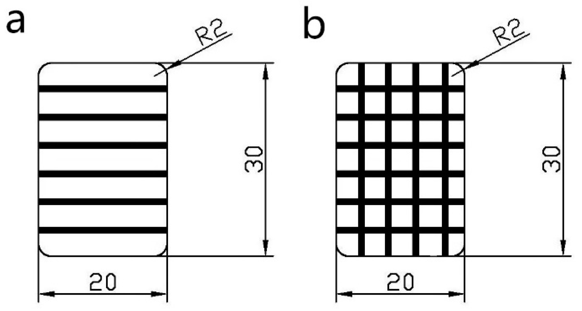
2.3. Sample Preparation

100 × 30 × 10 mm3 rectangular samples were made of semi-metallic, NAO, and ceramic brake pads by mechanical cutting. Using a DK77(DK7732, Huadong Group, Hangzhou, China) electric spark cutting machine produced by Dong Hua CNC company, the fragments of the gray cast iron brake hub were processed into 30 × 20 × 6 mm and 40 × 20 × 6 mm rectangular samples, respectively, and a 3 mm round hole was drilled on the upper part of 40 rectangular samples. Sample surfaces were polished with 80#, 360 #, 600#, and 1000# sandpaper to remove machining traces.
After cleaning and polishing the brake drum sample, the biomimetic cell model sample was prepared by laser melting with a Xl-500wf Nd:YAG pulsed laser (XL-500WF, Rofin, Munich, Germany) (Figure 2), with a maximum power output of 500 W. The laser parameters are shown in Table 2. Figure 3a shows the striped cell sample with a width of 1.2 mm. The striped cell was 45° to the edge, and the spacing between two adjacent cells was 4.8, 3.6, 2.4, and 1.2 mm. Figure 3b shows the grid cell specimen, which has a width of about 1.2 mm and a grid spacing of 6.0, 4.8, 3.6, and 2.4 mm.

2.4. Wear Tests

In order to better simulate the actual friction state during the operation of a brake system, due to the directionality of the friction between a brake hub and brake pad, we used a self-made linear reciprocating sliding wear test machine to perform wear experiments. The structure of the abrasion tester is shown in Figure 4, which was composed of a controller, motor, transmission mechanism, and abrasion test area. The rotation of the motor drives the connecting rod to perform a reciprocating motion, and the slideway ensures the horizontal distance in the direction of reciprocating motion. During wear tests, the brake pad was placed at the bottom, and the gray cast iron sample moved with the guide rail. The test load was 100 N, and the maximum speed of the servo motor was 70 r/min (the linear speed of the connecting rod movement in the corresponding wear area was 0.0823 m/s). For each rotation of the motor, the stroke of the connecting rod was 70 mm, and the wear time was set as 20 h (friction stroke 2412). After wear tests, the samples were ultrasonically cleaned (using alcohol) to remove wear debris from the surface of the brake pad sample, and then samples were weighed with an electronic balance with an accuracy of 0.0001 g. Each test was repeated 5 times (using a new sample for each test), and the average value of 5 tests was used as the final data result. All dry friction tests were performed at room temperature.

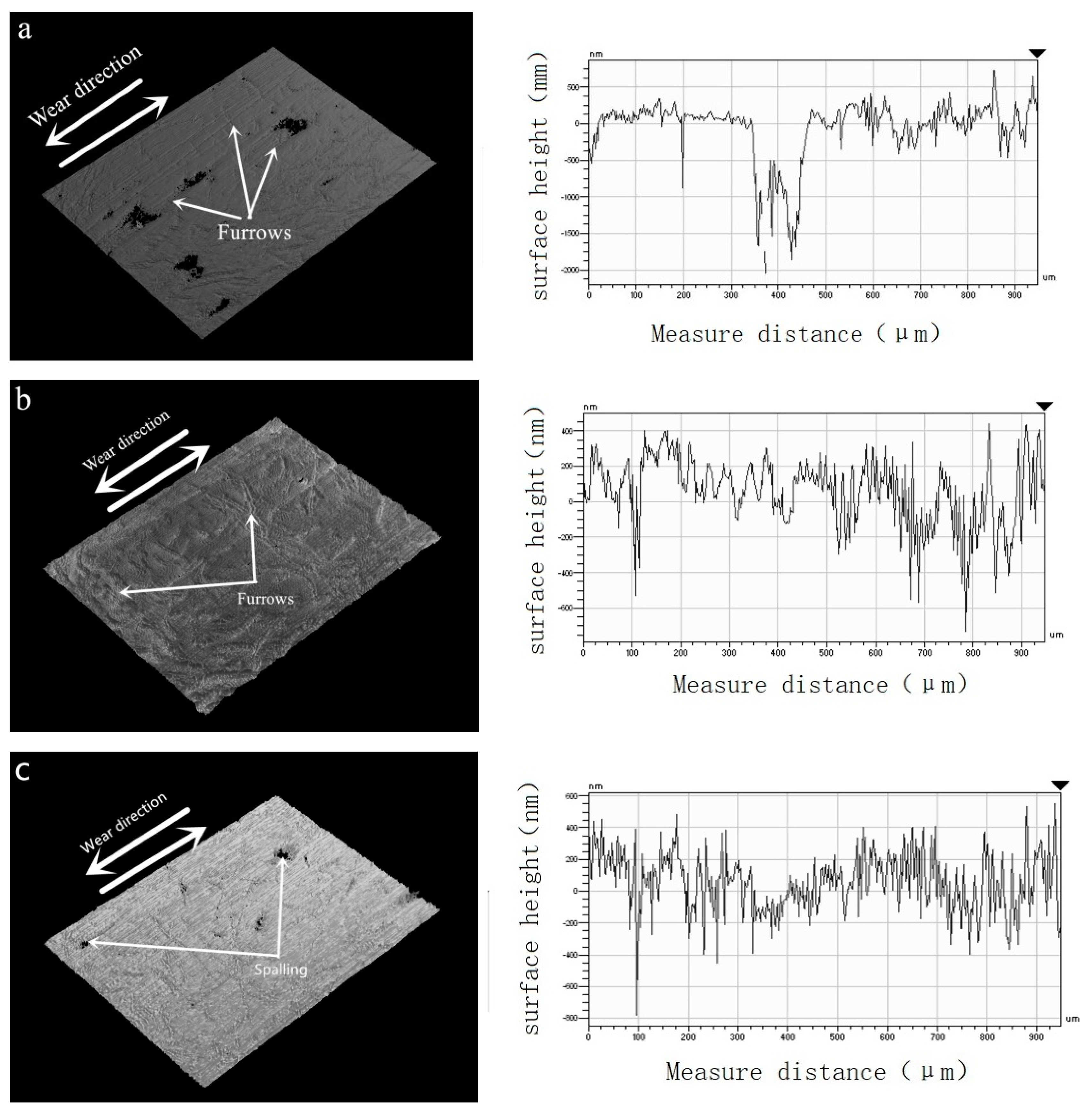
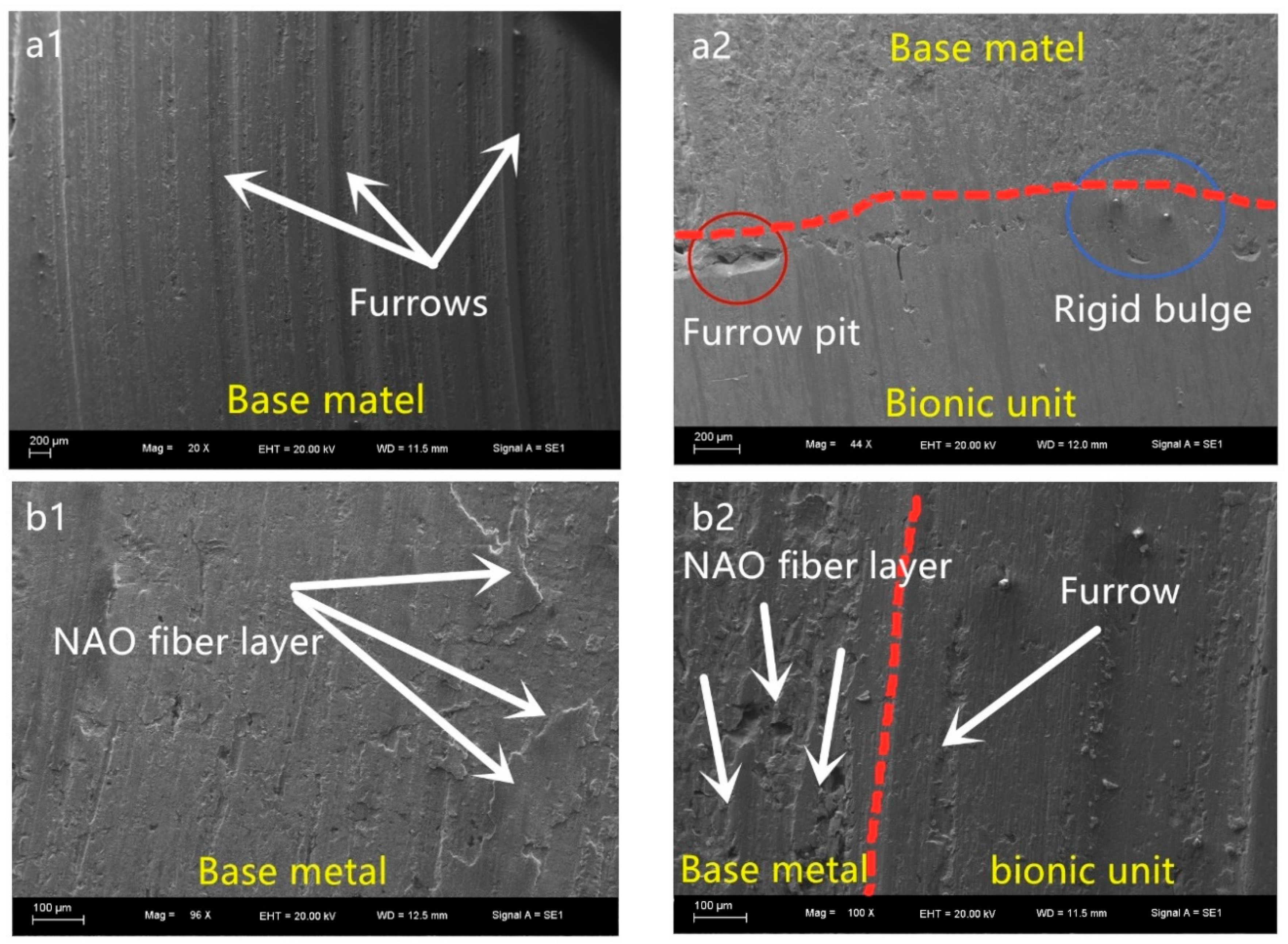
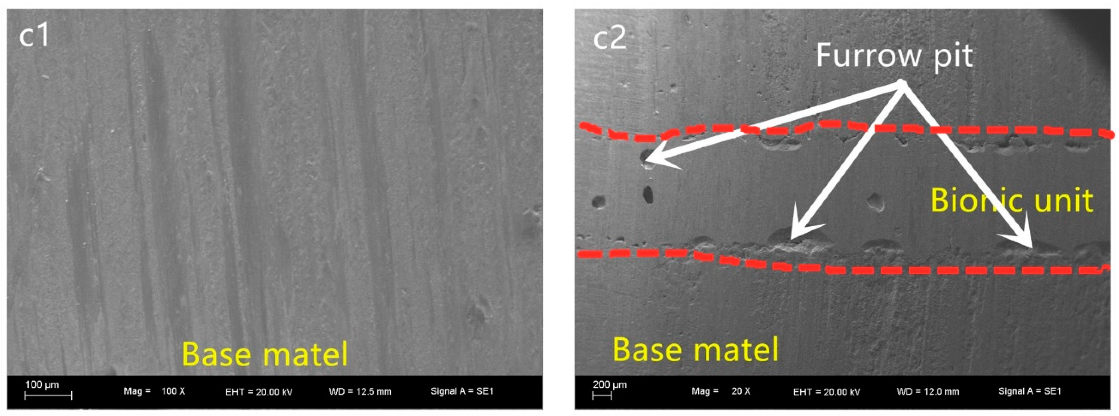
2.5. Microstructure and Wear Morphology Observations

A DK77 EDM was used to cut the laser-melted sample along its cross-section. Processing traces and oil stains on the cross-section were polished with different sandpaper grades. The samples were etched with a 4% nitric acid/alcohol solution to prepare them for metallographic observation. The morphology of biomimetic cells was observed under an optical microscope, and the cell without cracks and pores was selected for microstructure observation. A JEOL JSM-5600lv (SEM, Zeiss, Evo18, Oberkochen, Germany) scanning electron microscope (SEM) was used to observe the cross-section structure of bionic unit bodies. In addition, after the unit body sample and brake pad samples were worn, their surfaces were also observed under SEM and their wear morphology was recorded. In this process, the samples did not require polishing and corrosion.
To characterize the wear performance, in addition to measuring the mass change before and after wear, the wear morphology of different biomimetic unit models and different brake pads were compared and analyzed using three-dimensional laser confocal microscopy LEXT-OLS 3000 Olympus (OLYMPUS, PMG3, Tokyo, Japan).

3. Results and Discussion

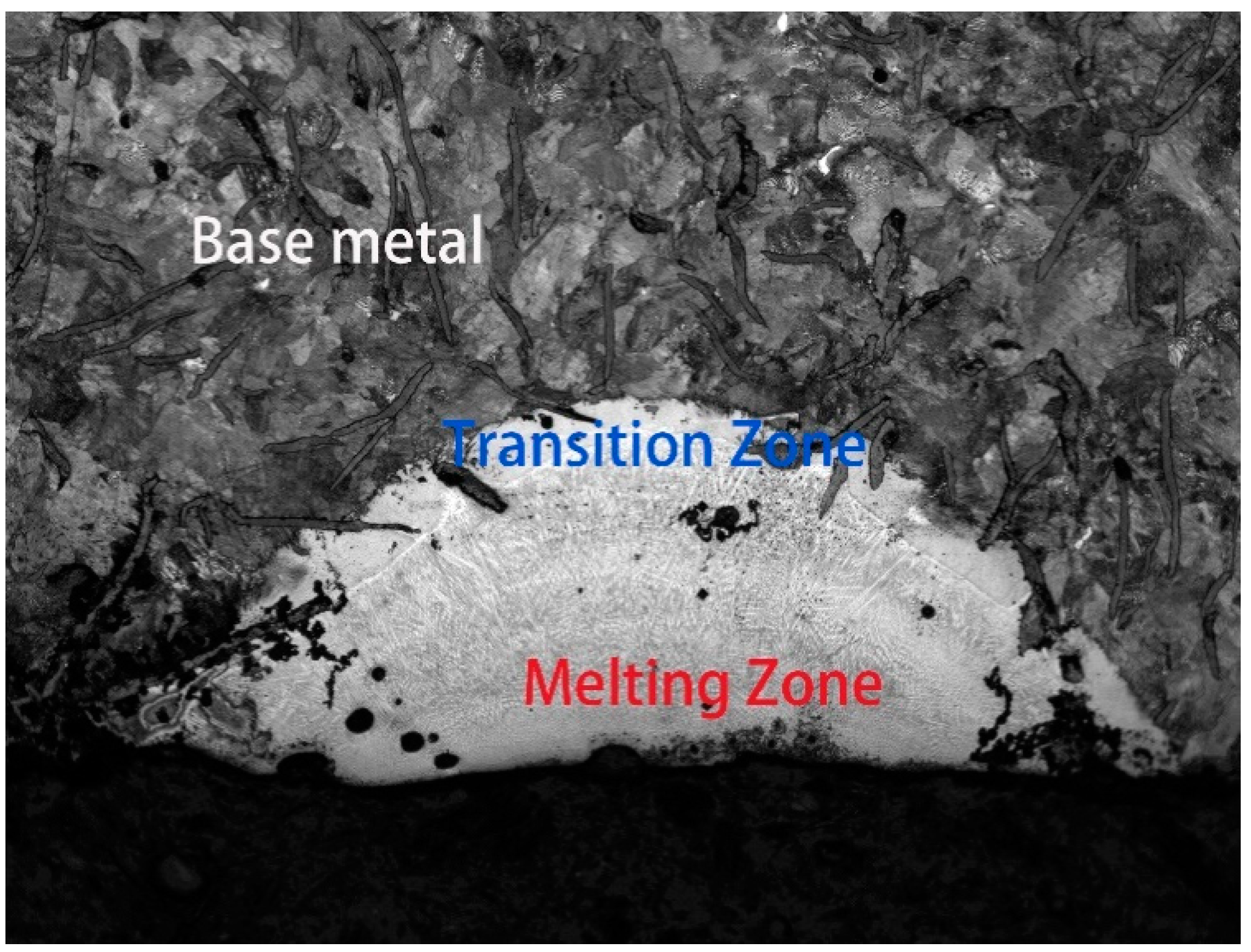
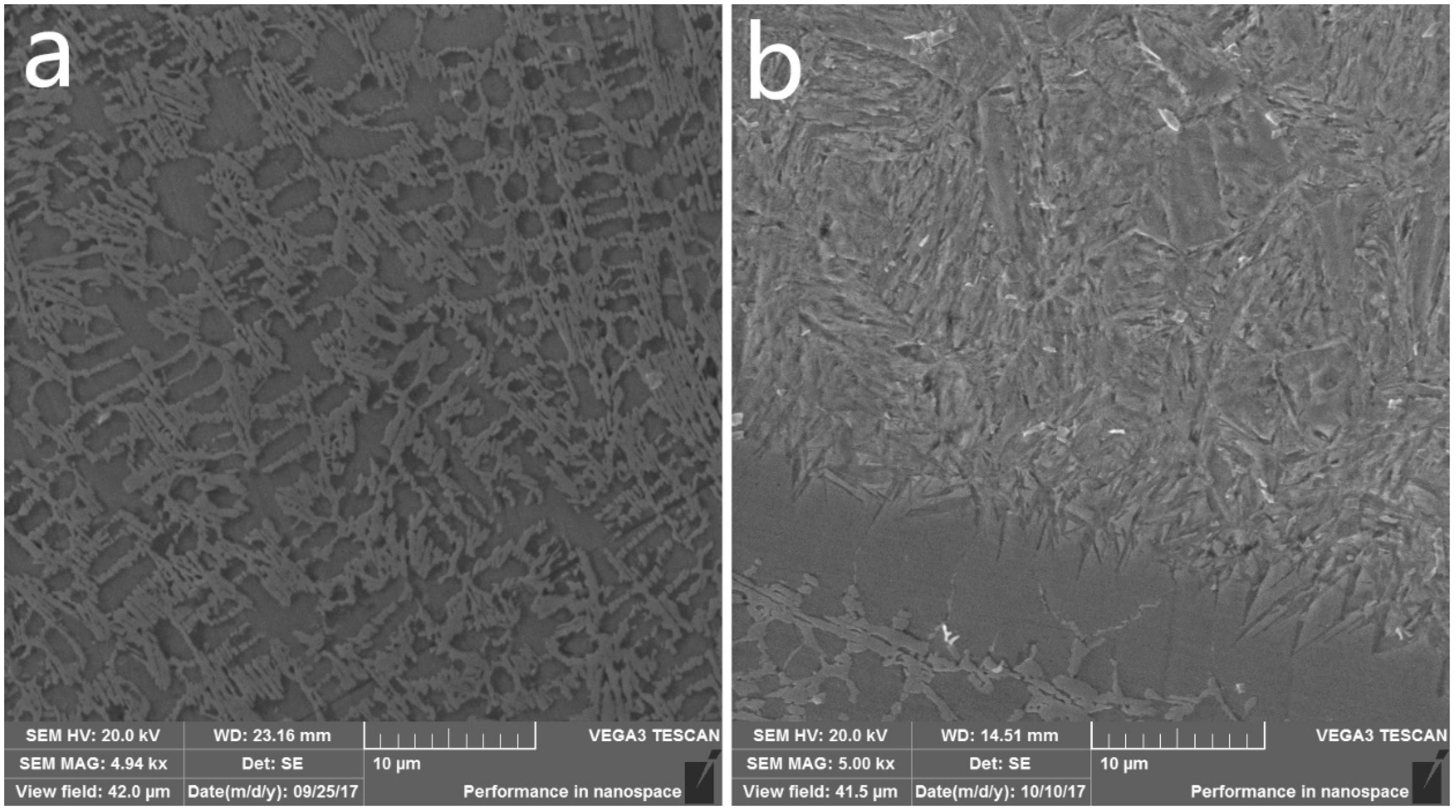
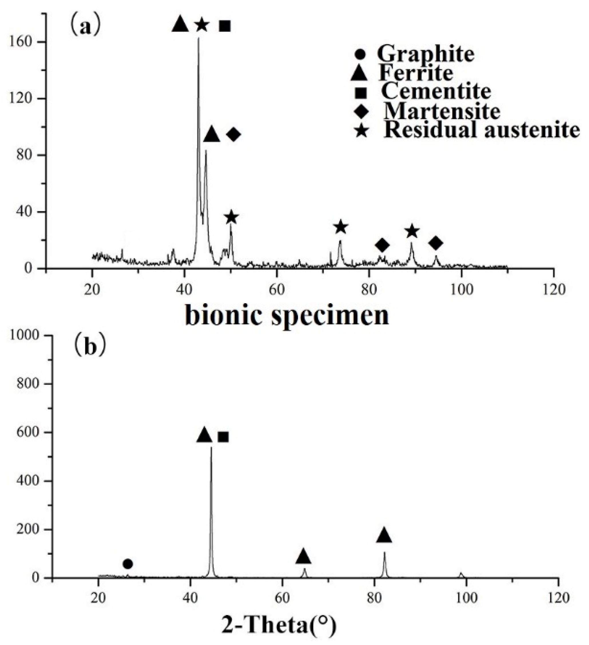
3.1. Structure of Gray Cast Iron Bionic Unit

Figure 5 shows the longitudinal section of the gray cast iron sample formed after laser melting. The white and bright area is the biomimetic unit, with a shape similar to the letter “U” [18,19], and the surface of the unit was slightly lower than the surface of the base metal by 0.1–0.2 mm. A small amount of melting defects and pores can also be seen, but this did not affect the performance of the bionic unit. Figure 6a shows that the matrix was a typical gray iron structure, with many lamellar pearlite structures mixed with larger graphite flakes. Ledeburite eutectics cells (colonies) were also observed in the interdendritic areas. Figure 6b shows the unit structure of the melting zone, which has a fine fishbone-like martensite dendrite structure. Figure 7 shows that martensite diffraction peaks appeared in the XRD (X-ray diffraction) spectrum of the biomimetic unit group. The bionic specimen was composed of martensite, austenite, and cementite. According to the solidification principle of alloys, when the composition of an alloy is fixed, the microstructure after solidification mainly depends on the front temperature gradient and solidification gradient of the liquid-solid interface [20]. The flake graphite also disappeared. During laser melting, the heating speed was very fast (103–106 °C), which rapidly melted the metal, dissolved the graphite completely, and caused a eutectic reaction to occur. The microstructure after eutectic transformation included eutectic austenite, cementite, and a small amount of primary untransformed austenite. The instantaneous high energy and the non-irradiated part produced a large temperature gradient, resulting in a great degree of supercooling. After melting, the metal instantly cooled and the cooling rate reached 106 °C/s, and martensite was formed. Most of the eutectic austenite and the primary austenite were transformed into martensite with a small amount of remaining austenite, so the microstructure of the melting zone is fine abnormal ledeburite (martensite + cementite + austenite).
Grain refinement occurred between the unit body and the matrix, and acicular martensite was observed in the melting area on the right side of the transition area due to the non-equilibrium phase formed by the rapid solidification speed and delayed diffusion of carbon [21,22].
In the wear process of a bionic surface and brake pad treated by laser melting, the main wear part of the bionic unit is the melting area [23]. The microhardness of the striped biomimetic unit, the remelting zone, and the untreated HT250 were measured by microhardness tester. Take 5 points from different positions for measurements, calculate the average value, and get t as shown in Table 3:
The hardness of striped biomimetic units and remelted units was much higher than that of untreated HT250. This was mainly due to the change in the material structure in the units, the finer grains in the unit, and a large amount of martensite, which greatly increased the hardness of the units. At the same time, the hardness of the remelted unit was slightly lower than that of the striped unit because, during laser treatment, due to the instantaneous high temperature, carbon experienced a large oxidation loss. The remelted point was repeatedly treated by laser, and the burning loss of carbon was more severe than in the striped unit. The carbon content determined the supersaturation of martensite, which affected its hardness, and decreased the hardness of the laser biomimetic unit at its melting point.

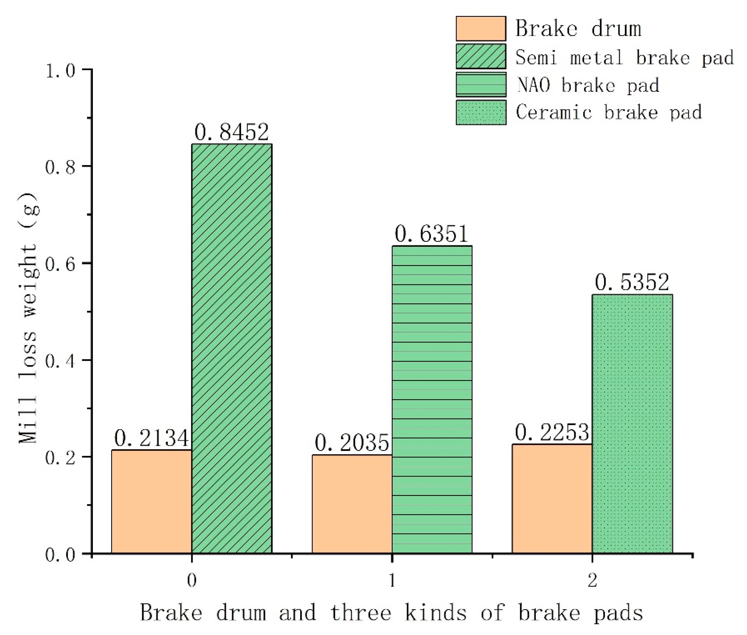
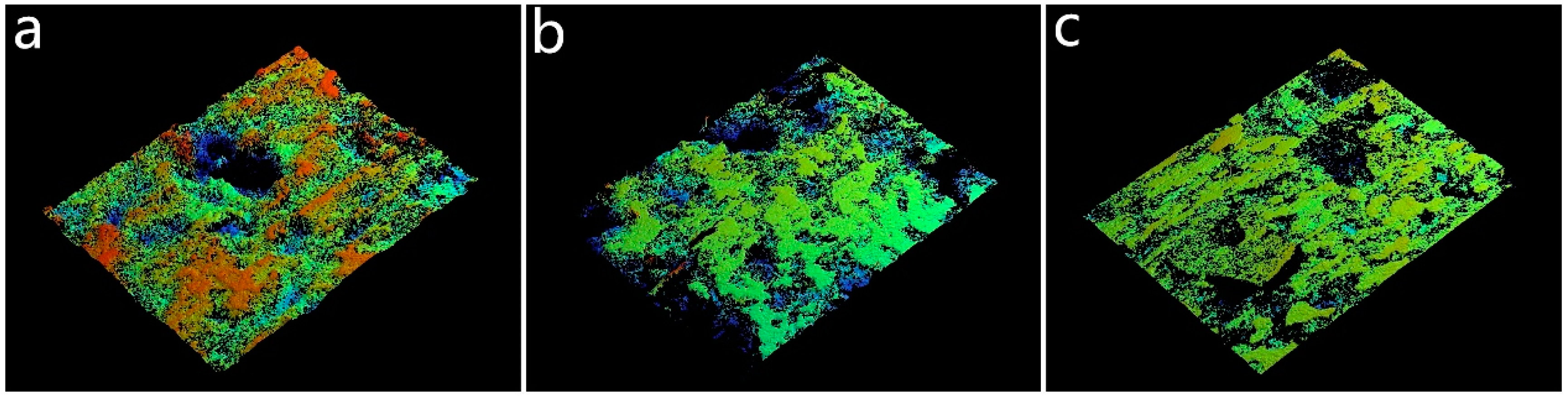
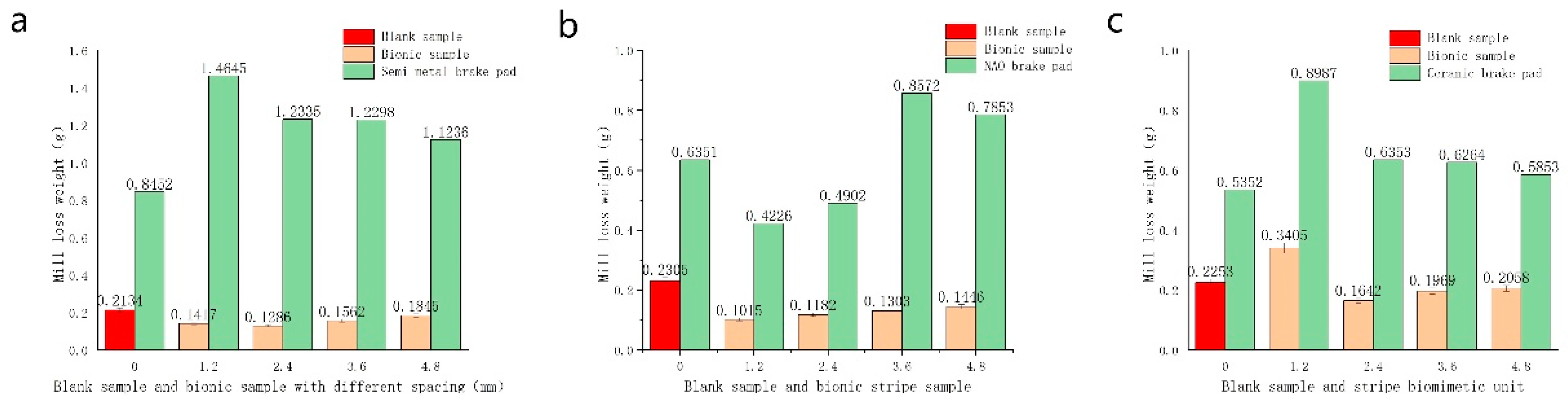
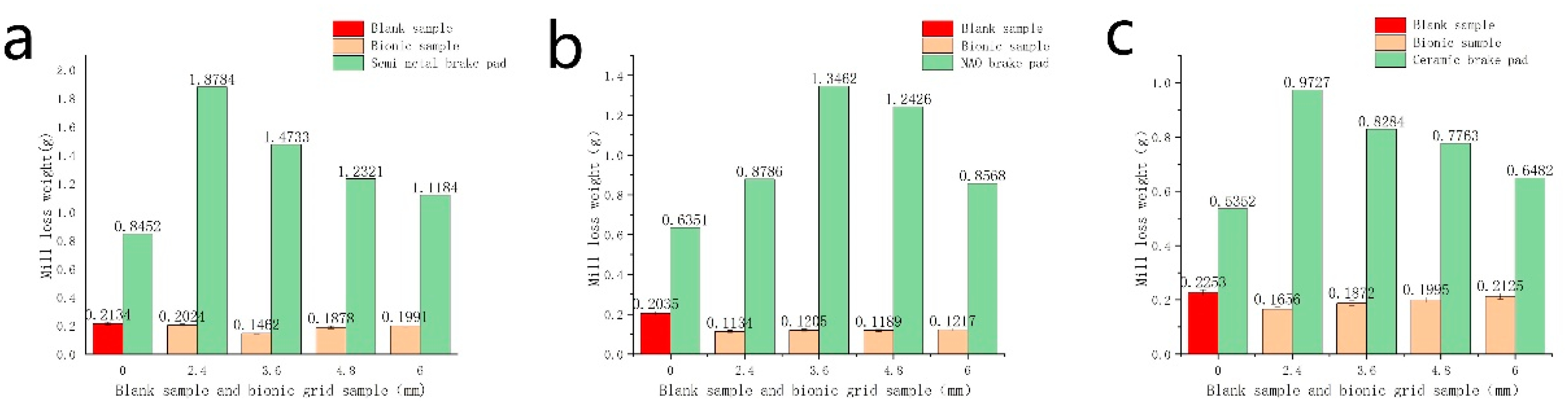
3.2. Wear Results of the Brake Pads and Blank Samples

Figure 8 shows the wear test results of the blank sample and different brake pads. The wear loss weight of the gray iron sample and the friction pad were significantly different. This was due to the different structures and hardness values, which changed the wear type and wear relationship.
It can be seen that the wear mechanisms of brake pads and blank brake hub samples were different. During the working process of the semi-metallic brake pads, steel semi-metallic fibers pierced the gray iron, causing significant cutting and peeling damage [24]. As the penetration depth of the metal fiber and the resistance of gray iron increased, the semi-metallic fiber peeled away from the brake pad structure and formed abrasive particles, which continued to cause wear on both sides. Therefore, the semi-metallic brake pad and the brake drum sample showed large weight loss due to wear. During the working process of NAO brake pads, a protective layer was formed on the surface of gray iron samples by consuming its own fiber and resin. During the wear process, there were no abrasive particles or chips, and adhesive wear occurred, which caused less damage to the brake hub but a larger weight loss. When the ceramic brake pad was used, ceramic particles in its structure had extremely high hardness values. After a period of work, the ceramic particles on the surface fall off the brake pad and cause abrasive wear between the brake pad and the brake drum. Since the ceramic particles are small, they are attached to the surface of the brake pad during wear and act on the brake drum sample. Therefore, the wear weight loss of the brake drum specimen which acted on the ceramic brake pad was the largest, and the weight loss of the ceramic brake pad specimen was the smallest among the three brake pads [25].
Scanning the wear scars on the surface of the brake pad can reflect the deformation and failure form of the material during the wear process, which can be used to determine the wear mechanism. Figure 9 and Figure 10 show the three-dimensional surface morphology photos of different types of brake pads and gray iron blank samples after wear, respectively. In Figure 9a, due to the presence of steel fibers, the surface hardness distribution of semi-metallic brake pads is uneven, the surface was also uneven after wear, and no obvious micro peeling was observed. Figure 10a shows that there are deep scratches on the surface of the brake drum specimen along the parallel wear direction, and a large number of pits caused by peeling were scattered across the surface of the specimen. In Figure 9b, the surface of the NAO brake pad was smooth, and the original non-metallic fiber bulge was ground smooth. At the same time, no deep wear marks were observed on the surface. In Figure 10b, a large number of scale-like surface bulges appeared on the surface of the brake drum sample, with slight wear marks on the edge of the scale structure. From a macroscopic view, a layer of black film was observed on the surface of the gray iron sample. This was because, during the wear process, organic fibers and resins in the NAO brake pads were oxidized and fell off, and the falling materials formed fine wear debris and a thin film that adhered to the surface of gray iron samples under pressure. In Figure 9c, the wear surface smoothness of the ceramic brake pad was lower than that of the NAO brake pad, with obvious ceramic particle bulges and shallow wear marks. Figure 10c shows that there are many scratches and pits on the surface of the brake drum sample, but the scratches were shallower than that of the semi-metal and NAO brake pads because the ceramic brake pads have very small particles. During wear, the ceramic particles are pressed into the surface of the cast-iron brake hub, causing wear along the sliding direction.
Figure 11 shows the wear result diagram of interactions between the striped bionic unit sample and three kinds of brake pads. The change between the striped bionic model with different spacings and the wear amount of different brake pads significantly changed. Figure 12 shows an electron micrograph of the wear morphology of the blank sample and the bionic sample. Figure 11a shows the wear results of semi-metallic brake pads and bionic samples and shows that the wear amount of bionic samples was 11.6%–32.3% less than that of blank samples; however, the brake pad wear increased significantly. This was because the bionic surface of the gray cast iron sample changed from a single gray iron material surface to a bionic surface obtained by metallurgically combining the soft and hard phases of the fusion unit and matrix. The hardness of the fused unit was higher than that of the matrix, which was equivalent to the steel metal fiber in the semi-metal brake pad. It can be found from the comparative picture of the wear morphology of the blank sample, stripe unit, and brake pad in Figure 12(a1,a2) that when the brake was applied, metal fibers penetrated the base metal, causing a ploughing effect on the base metal. When the metal fiber passed through the stripe unit, the harder unit cut off the fiber, and the cut metal fiber continued to wear the brake pad and bionic sample due to the abrasive particles. At the same time, due to the cutting effect of the metal fiber, the metal fiber was separated from the brake pad in the form of peeling, which increased the wear loss of the brake pad by 34.6%–52.1%. There were obvious tangent scratches on the surface of the unit and a high boundary between the unit and the substrate after wear.
The wear results show that decreasing the cell spacing decreased the wear amount accordingly. When the unit spacing density is too small, the wear of the bionic sample increased because increasing the hard unit increased the surface hardness and brittleness of the hard unit. Decreasing the matrix area caused the hard unit to lose the support and buffer. Under the action of metal fibers and debris, the hard matrix experienced brittle fracture and peeling, which increased the wear. As the unit spacing decreased, the wear of the brake pads increased. When the unit spacing was reduced to 2.4 mm, the wear of the brake pad increased due to decreasing the unit spacing and increasing the hard area on the surface. When the distance between the striped unit and the semi-metal brake pad was 2.4 mm, the best matching effect was achieved.
The wear results of the NAO brake pad and stripe-type bionic specimen were also examined. As the distance between the striped units decreased, the weight loss of NAO brake pads increased correspondingly, but it had little effect on the wear results. From Figure 12(b1,b2), it can be seen that the wear morphology of the substrate was basically the same regardless of the blank sample or the bionic sample. The surface of the unit body was very smooth because the organic fibers of the brake pad formed a wear layer on the surface of the sample during the high-pressure wear process of the NAO brake pad. From the wear morphology, it can be seen that the fiber surface had a fish scale appearance. In terms of the matching of NAO brake pads and bionic discs, according to the wear results, when the distance between the NAO brake pads and brake discs was less than 3.6 mm, a protective layer was formed during the wear process of NAO brake pads, and the brake discs tended to remain stable. When the distance between the NAO brake pad and the bionic brake disc was 1.2 mm, the best matching effect was achieved, and the mutual wear was the lowest.
As shown in Figure 11c, as the distance between the bionic unit and the ceramic brake pad decreased, the wear of the brake disc first decreased and then increased. As shown in Figure 12(c1,c2), the surface of the blank sample was relatively smooth after it was worn with the ceramic brake pad, due to the uniform wear between the fine ceramic particles and the blank sample after peeling off from the brake pad surface. Therefore, at large distances between the bionic samples, a larger number of soft substrates were present on the bionic surface, and the ceramic abrasive particles of the ceramic brake pads caused higher wear on the brake disc samples. Due to the excessive wear of the soft matrix, the support around the hard unit was lost, and the hard unit was peeled and dropped during the wear process due to ceramic particles. As the distance between the cells decreased, the wear of the biomimetic samples was gradually reduced because the number of hard cells gradually increased, which resisted the wear by ceramic particles on the matrix. However, when the total area of the unit on the bionic surface increased to a certain amount (more than 60%), the wear amount increased in the opposite direction. This occurred due to a lack of necessary support of the hard unit when the soft matrix was too small and due to the peeling effect from ceramic particle wear.
Figure 13 shows the wear results between the mesh bionic specimen and different brake pads. The results show that as the grid cell spacing decreased, the wear of the bionic samples first decreased and then increased. The wear of the semi-metallic brake pads increased, especially when the spacing value was the smallest, at which point the brake pads and the bionic samples reached their maximum wear values. This was caused by the reduction in the base area, the lack of necessary support and protection of the unit, and the excessive wear of the metal fibers of the brake pad. There are some differences between the wear results of the NAO type brake pad and the bionic grid and stripe samples. The wear amount of the mesh bionic specimen showed very little changes, which were independent of the size of the cell spacing; however, the wear loss of the brake pads increased first and then decreased. Therefore, the optimal matching effect was achieved when the distance between the grid brake pads and the NAO brake pads was 6.0 mm. As the cell spacing decreased, the wear loss of the grid bionic samples and the ceramic brake pads first decreased and then increased, while the wear loss of the brake pads slowly increased. The wear trend was similar to that of the stripe sample. When the distance between the cells was the largest, the soft matrix was excessively worn by ceramic particles, and the cells lost support and protection, causing the ceramic particles to peel off from the surface of the matrix. When the distance between the cells decreased, the cells bore the wear consumption, protected the surface of the matrix from damage, and improved the wear resistance. The cell density increased at the minimum cell spacing, and the wear of ceramic particles intensified. The wear-loss weight of both sides was high due to an unsatisfactory matching state.

4. Conclusions

The wear results between bionic specimens and the brake pad were due to different wear mechanisms. The wear matching relationship between the bionic specimen and the semi-metallic brake pad was determined by the size of the metal fiber of the semi-metallic brake pad and its distance between the bionic model. The best matching relationship was obtained when the spacing of the stripe cell was 2.4 mm and the grid cell spacing was 3.6 mm. The matching relationship between the NAO brake pad and the bionic sample was determined by observing the speed at which the fiber film, which formed by the NAO brake pad, fell off during the wearing process. At the maximum or minimum spacings, a better matching relationship was obtained. Therefore, when the spacing of the stripe unit was 1.2 mm and the spacing of the grid unit was 2.4 mm, the best matching relationship was obtained. The matching relationship between the ceramic brake pad and the bionic sample was basically proportional to the density of the bionic sample cell. A better matching effect was achieved at a larger cell density. However, considering the working loss of the brake pad itself, the best matching effect was obtained when the spacing between the stripe cell was 2.4 mm and the spacing between the grid cell was 3.6 mm. This was basically consistent with the semi-metallic brake pad. Overall, the best matching mechanism between the NAO brake pads and bionic samples was obtained by combining the wear matching mechanism of three kinds of brake pads and bionic samples.

Author Contributions

Data curation, Q.W. and T.Z.; Formal analysis, H.Y.; Methodology, H.Y.; Resources, Q.W. and T.Z.; Supervision, H.Z. All authors have read and agreed to the published version of the manuscript.

Funding

This work was supported by Project 985-High Performance Materials of Jilin University, Project 985-Bionic Engineering Science and Technology Innovation, National Natural Science Foundation of China (U1601203), and double first-class project by Jilin Province and Jilin University (SXGJXX2017-14).

Conflicts of Interest

The authors declare no conflict of interest regarding the publication of this paper. I would like to declare on behalf of my co-authors that the work described was original research that has not been published previously, and not under consideration for publication elsewhere, in whole or in part. All the authors listed have approved the manuscript that is enclosed.

References

  1. Dickinson, M.H. Bionics: Biological insight into design. Proc. Natl. Acad. Sci. USA 1999, 96, 14208–14209. [Google Scholar] [CrossRef] [PubMed] [Green Version]
  2. Ren, L.Q.; Cong, Q.; Tong, J.; Chen, B.C. Reducing adhesion of soil against loading shovel using bionic electro-osmosis method. J. Terrramech. 2001, 38, 211–219. [Google Scholar] [CrossRef]
  3. Ren, L.Q.; Han, Z.W.; Li, J.J.; Tong, J. Effects of non-smooth characteristics on bionic bulldozer blades in resistance reduction against soil. J. Terrramech. 2003, 39, 22–30. [Google Scholar] [CrossRef]
  4. Tong, J.; Almobarak, M.A.M.; Ma, Y.H.; Ye, W.; Zheng, S. Biomimetic anti-abrasion surface of a cone form component against soil. J. Bionic Eng. 2010, 7, S36–S42. [Google Scholar] [CrossRef]
  5. Kamat, S.; Su, X.; Ballarini, R.; Heuer, A.H. Structural basis for the fracture toughness of the shell of the conch Strombusgigas. Nature 2000, 405, 1036–1040. [Google Scholar] [CrossRef]
  6. Liu, Y.; Zhou, H.; Su, H.; Yang, C.Y.; Cheng, J.Y.; Zhang, P.; Ren, L. Effect of electrical pulse treatment on the thermal fatigue resistance of bionic compacted graphite cast iron processed in water. Mater. Des. 2012, 39, 344–349. [Google Scholar] [CrossRef]
  7. Meng, C.; Zhou, H.; Zhang, H.F.; Tong, X.; Cong, D.L.; Wang, C.W.; Ren, L. The comparative study of thermal fatigue behavior of H13 die steel with biomimetic non-smooth surface processed by laser surface melting and laser cladding. Mater. Des. 2013, 51, 886–893. [Google Scholar] [CrossRef]
  8. Cong, D.L.; Zhou, H.; Yang, M.Q.; Zhang, Z.H.; Zhang, P.; Meng, C.; Ren, L. The mechanical properties of H13 die steel repaired by a biomimetic laser technique. Opt. Laser Technol. 2013, 53, 1–8. [Google Scholar] [CrossRef]
  9. Zhou, H.; Zhang, P.; Sun, N.; Wang, C.T.; Lin, P.Y.; Ren, L.Q. Wear properties of compact graphite cast iron with bionic units processed by deep laser cladding WC. Appl. Surf. Sci. 2010, 256, 6413–6419. [Google Scholar] [CrossRef]
  10. Tong, X.; Zhou, H.; Chen, L.; Li, C.; Zhang, Z.; Ren, L. Effects of c content on the thermal fatigue resistance of cast iron with biomimetic non-smooth surface. Int. J. Fatigue 2008, 30, 1125–1133. [Google Scholar]
  11. Liang, Y.; Huang, H.; Li, X.; Ren, L. Fabrication and Analysis of the Multi-Coupling Bionic Wear-Resistant Material. J. Bionic Eng. 2010, 7, S24–S29. [Google Scholar] [CrossRef]
  12. Ren, L.Q.; Liang, Y.H. Biological couplings: Classification and characteristic rules. Sci. China Ser. E Technol. Sci. 2009, 52, 2791–2800. [Google Scholar] [CrossRef]
  13. Ren, L. Progress in the bionic study on anti-adhesion and resistance reduction of terrain machines. Sci. China Ser. E Technol. Sci. 2009, 52, 273–284. [Google Scholar] [CrossRef]
  14. Ren, L.Q.; Liang, Y.H. Functional characteristics of dragonfly wings and progress in bionic research. Sci. China Ser. E Technol. Sci. 2013, 4, 11–25. [Google Scholar]
  15. Yuan, Y.; Zhang, P.; Zhao, G.; Gao, Y.; Tao, L.; Chen, H.; Ren, L. Effects of Laser Energies on Wear and Tensile Properties of Biomimetic 7075 Aluminum Alloy. J. Mater. Eng. Perform. 2018, 27, 1361–1368. [Google Scholar] [CrossRef]
  16. Chen, Z.; Zhu, Q.; Wang, J.; Yun, X.; He, B.; Luo, J. Behaviors of 40Cr steel treated by laser quenching on impact abrasive wear. Opt. Laser Technol. 2018, 103, 118–125. [Google Scholar] [CrossRef]
  17. Faisal, T.R.; Abad, E.M.K.; Hristozov, N.; Pasini, D. The Impact of Tissue Morphology, Cross-Section and Turgor Pressure on the Mechanical Properties of the Leaf Petiole in Plants. J. Bionic Eng. 2010, 7, S11–S23. [Google Scholar] [CrossRef]
  18. Zhou, H.; Tong, X.; Zhang, Z.; Li, X.; Ren, L. The thermal fatigue resistance of cast iron with biomimetic non-smooth surface processed by laser with different parameters. Mater. Sci. Eng. A 2006, 428, 141–147. [Google Scholar] [CrossRef]
  19. Sui, Q.; Zhou, H.; Zhang, D.; Chen, Z.; Zhang, P. Imposed Thermal Fatigue and Post-Thermal-Cycle Wear Resistance of Biomimetic Gray Cast Iron by Laser Treatment. Metall. Mater. Trans. A 2017, 48, 3758–3769. [Google Scholar] [CrossRef]
  20. Lu, H.; Liu, M.; Yu, D.; Zhou, T.; Zhou, H.; Zhang, P.; Bo, H.; Su, W.; Zhang, Z.; Bao, H. Effects of Different Graphite Types on the Thermal Fatigue Behavior of Bionic Laser-Processed Gray Cast Iron. Metall. Mater. Trans. A 2018, 49, 5848–5857. [Google Scholar] [CrossRef]
  21. Shen, L.; Li, C.L. Effect of laser melting processing on the microstructure and wear resistance of gray cast iron. Wear 1991, 147, 195–206. [Google Scholar]
  22. Liu, Y.; Zhou, H.; Yang, C.Y.; Chen, J.Y. Thermal Fatigue Resistance of Bionic Compacted Graphite Cast Iron Treated with the Twice Laser Process in Water. Strength Mater. 2015, 47, 170–176. [Google Scholar] [CrossRef]
  23. Wang, X.; Zhang, W.; Guo, B. Investigation on the Thermal Crack Evolution and Oxidation Effect of Compacted Graphite Iron Under Thermal Shock. J. Mater. Eng. Perform. 2015, 24, 3419–3425. [Google Scholar] [CrossRef]
  24. Lim, C.-H.; Goo, B.-C. Development of compacted vermicular graphite cast iron for railway brake discs. Met. Mater. Int. 2011, 17, 199–205. [Google Scholar] [CrossRef]
  25. Yang, X.; Zhang, Z.; Wang, J.; Ren, L. Investigation of nanomechanical properties and thermal fatigue resistance of gray cast iron processed by laser alloying. J. Alloys Compd. 2015, 626, 260–263. [Google Scholar] [CrossRef]
Figure 1. Three kinds of brake pads. (a) Semi-metallic brake pads macroscopic appearance and microstructure; (b) organic asbestos-free brake pads macroscopic appearance and microstructure; (c) ceramic brake pads macroscopic appearance and microstructure.
Metals 10 00184 g001
Figure 2. The schematic diagram of laser processing.
Metals 10 00184 g002
Figure 3. Biomimetic unit model. (a) The stripe biomimetic cell model; (b) the mesh biomimetic cell model.
Metals 10 00184 g003
Figure 4. Linear reciprocating sliding friction and wear tester.
Metals 10 00184 g004
Figure 5. Section microstructure of a biomimetic unit.
Metals 10 00184 g005
Figure 6. Electron micrograph of the microstructure in the melting and transition zone of a biomimetic unit. (a) The melting zone; (b) the transition zone.
Metals 10 00184 g006
Figure 7. XRD (X-ray diffraction) analysis of a biomimetic unit. (a) bionic specimen surface of re-melting units; (b) non-bionic specimen surface.
Metals 10 00184 g007
Figure 8. Wear test results of the blank sample and different brake pads.
Metals 10 00184 g008
Figure 9. Three-dimensional surface morphology photos of different types of brake pads; (a) semi-metallic brake pads; (b) organic asbestos-free brake pads; (c) ceramic brake pads.
Metals 10 00184 g009
Figure 10. Surface morphology of brake drum specimen grinded with brake pad. (a) The surface morphology of the brake drum specimen grinded against the Semi-metallic Brake Pad; (b) the surface morphology of the brake drum specimen grinded against the organic asbestos-free brake pads; (c) the surface morphology of the brake drum specimen grinded against the organic asbestos-free brake pads.
Metals 10 00184 g010
Figure 11. Wear result diagram of interactions between the striped bionic unit sample and three kinds of brake pads. (a) The wear of bionic samples and semi-metallic brake ads; (b) the wear of bionic samples and organic asbestos-free (NAO) brake pads; (c) the wear of bionic samples and ceramic brake pads.
Metals 10 00184 g011
Figure 12. Surface wear morphology of biomimetic samples. (a1) The wear morphology of blank and semi metal brake pads; (a2) the wear morphology of bionic and semi metal brake pads; (b1) the blank specimen and wear morphology of a NAO brake pad; (b2) the bionic specimen and wear morphology of a NAO brake pad; (c1) the wear morphology of blank samples and ceramic brake pads; (c2) the wear morphology of bionic samples and ceramic brake pads.
Metals 10 00184 g012aMetals 10 00184 g012b
Figure 13. Wear test results of grid specimen and different brake pads. (a) The wear of grid bionic samples and semi-metallic brake ads; (b) the wear of grid bionic samples and organic asbestos-free (NAO) brake pads; (c) the wear of grid bionic samples and ceramic brake pads.
Metals 10 00184 g013
Table 1. Chemical compositions of nodular cast iron.
ElementCSiMnPSMgFe
Composition (wt.%)3.562.560.710.030.030.02Bale
Table 2. Laser parameters.
Electric CurrentPulse DurationFrequencyDefocus AmountLaser Energy Density
(A)(ms)(Hz)(mm)(J/mm2)
120715155144.7
Table 3. The hardness value.
PositionMatrixStriated UnitUnit Weight Melting Point
Hardness Value/HV303665635

