Evolution of Fretting Wear Behaviors and Mechanisms of 20CrMnTi Steel after Carburizing

 ,
,
Abstract
1. Introduction
2. Material Preparation and Experimental Methods
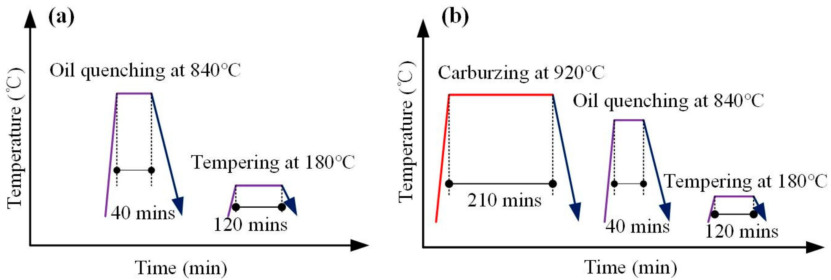
2.1. Material Preparation
2.2. Microstructure Characterization
2.3. Fretting Wear Test
3. Results and Discussions
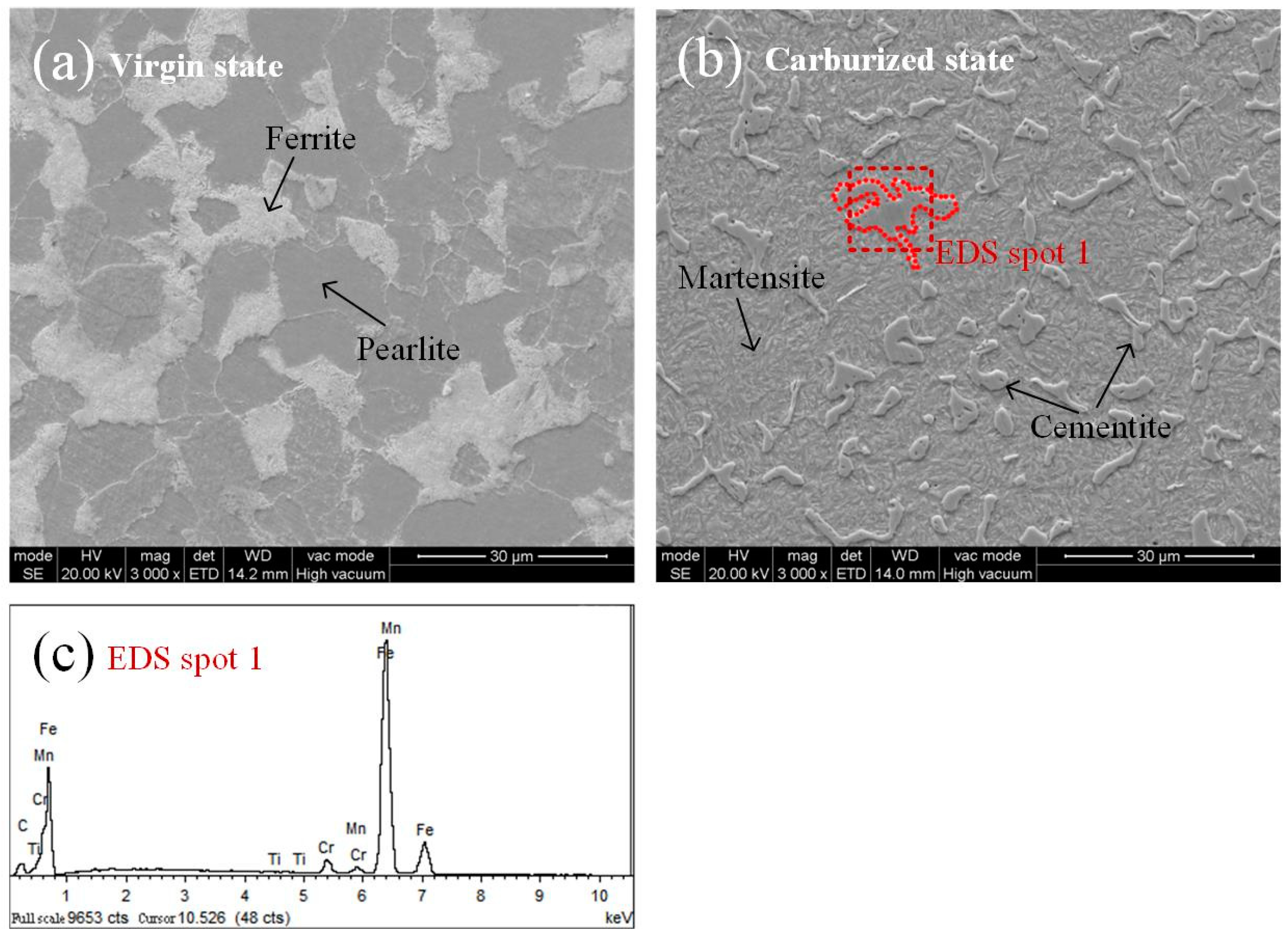
3.1. Microstructure
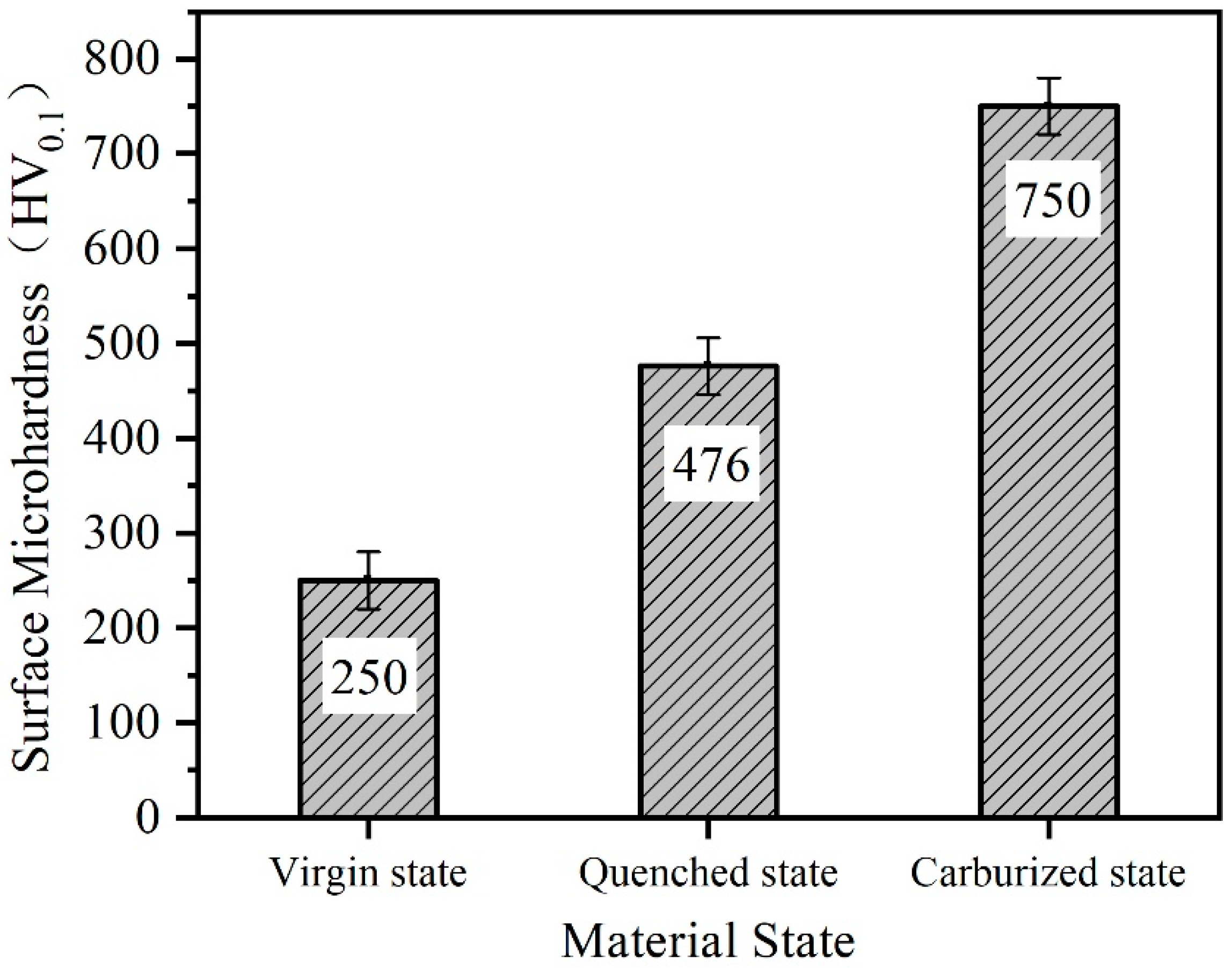
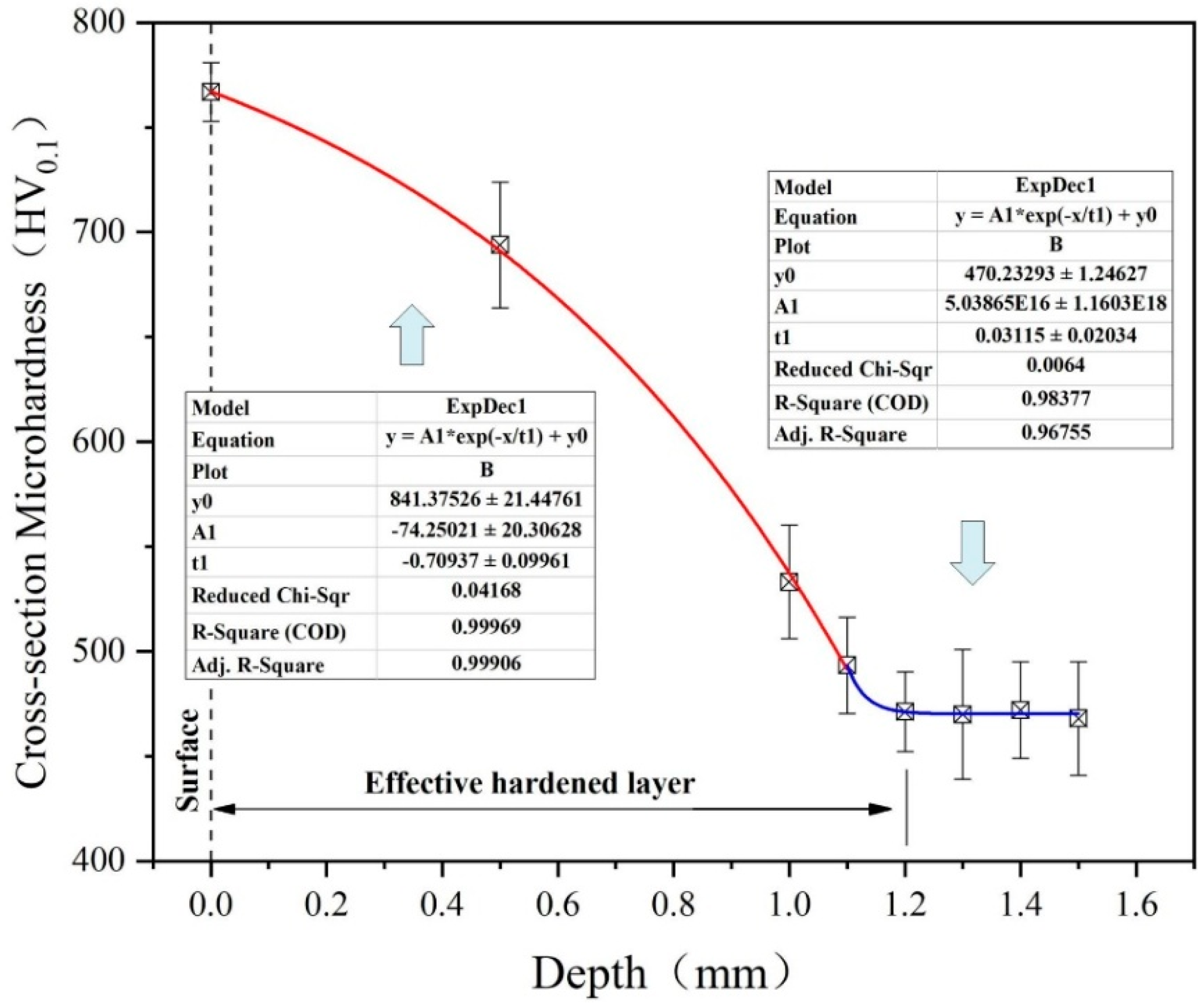
3.2. Microhardness
3.3. Effect of Carburizing Treatment on Wear Behaviors
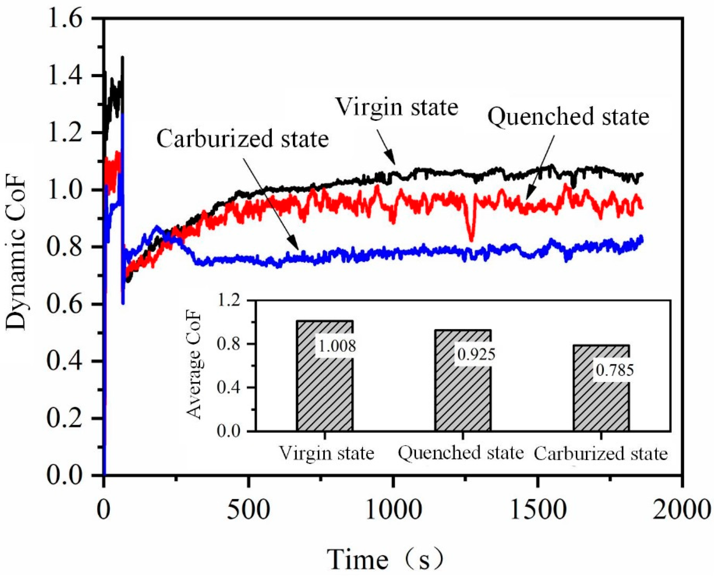
3.3.1. Coefficient of Friction
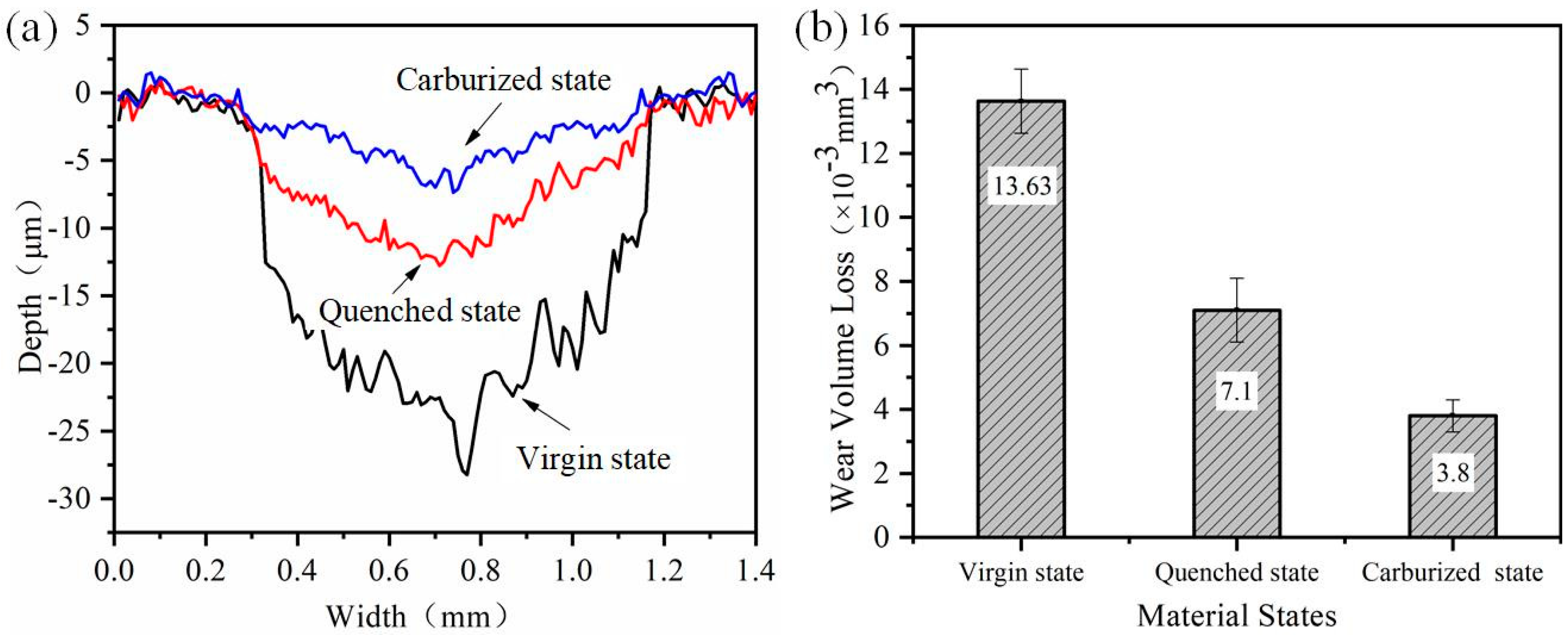
3.3.2. Wear Volume Loss
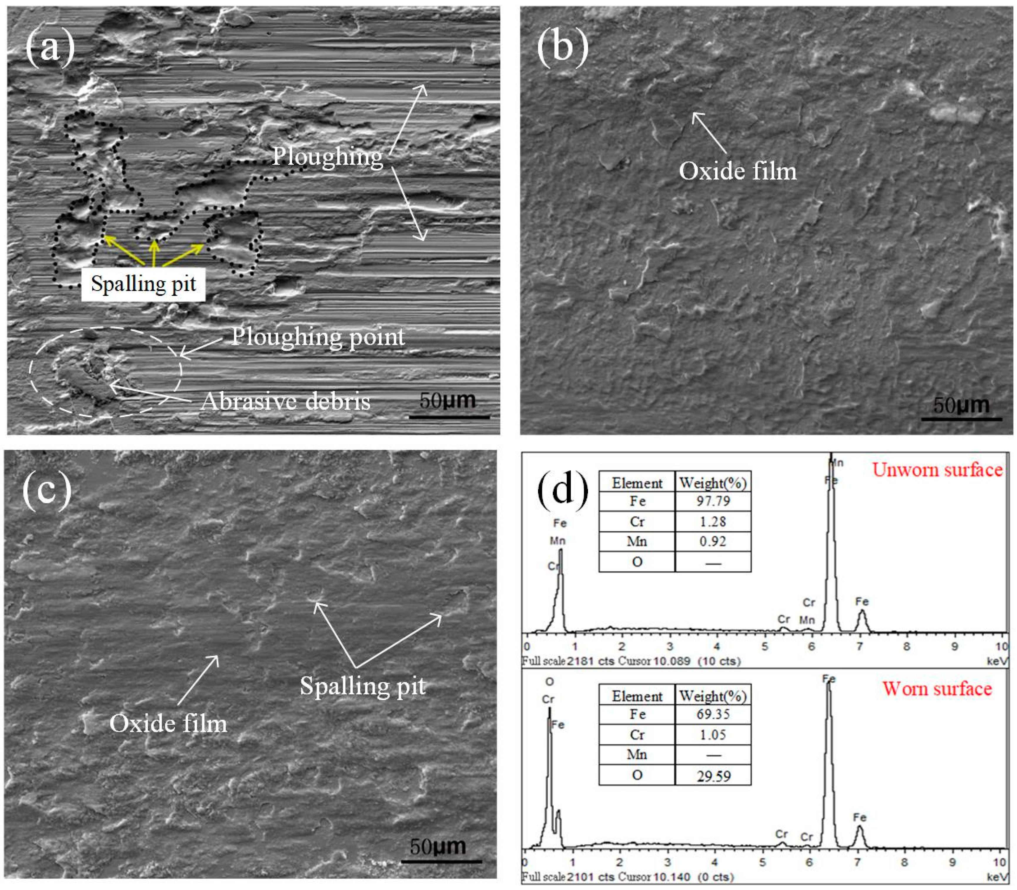
3.3.3. Variation of Wear Mechanism
3.4. Wear Behaviors of Carburized State under Different Loads and Reciprocating Frequencies
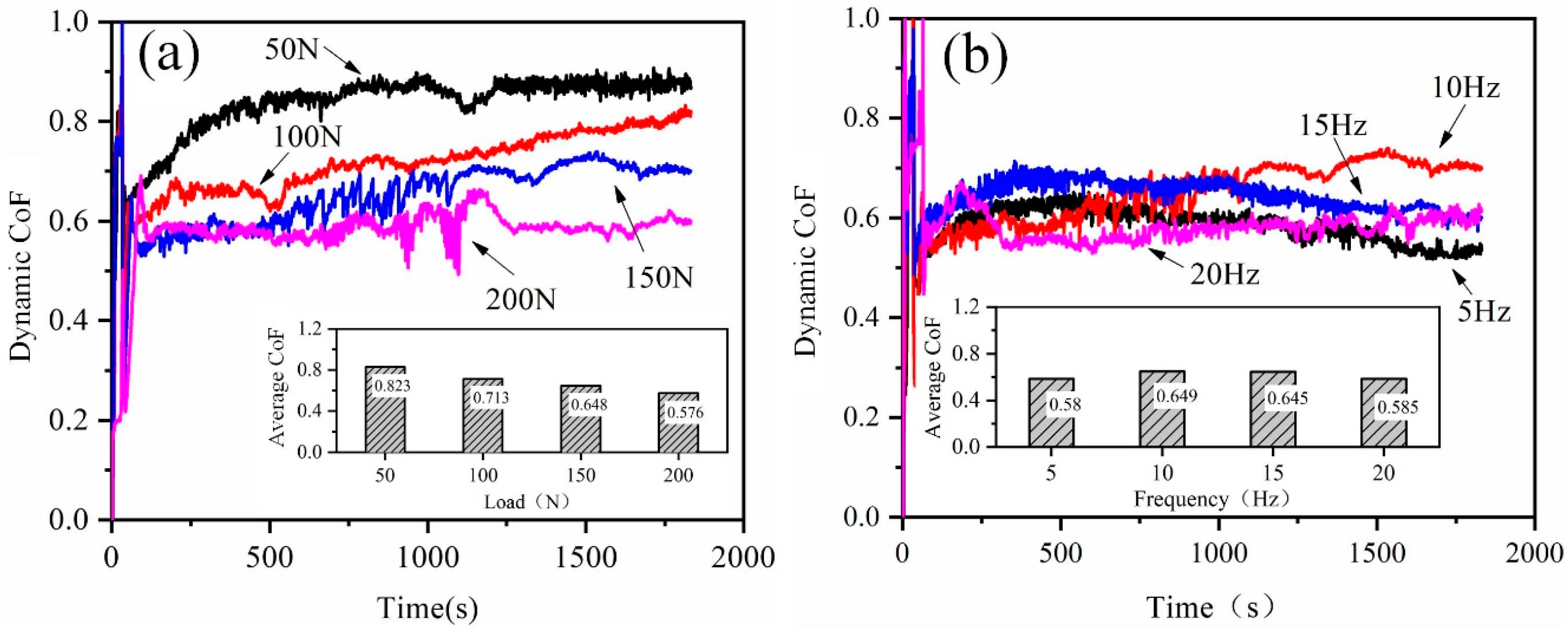
3.4.1. Coefficient of Friction
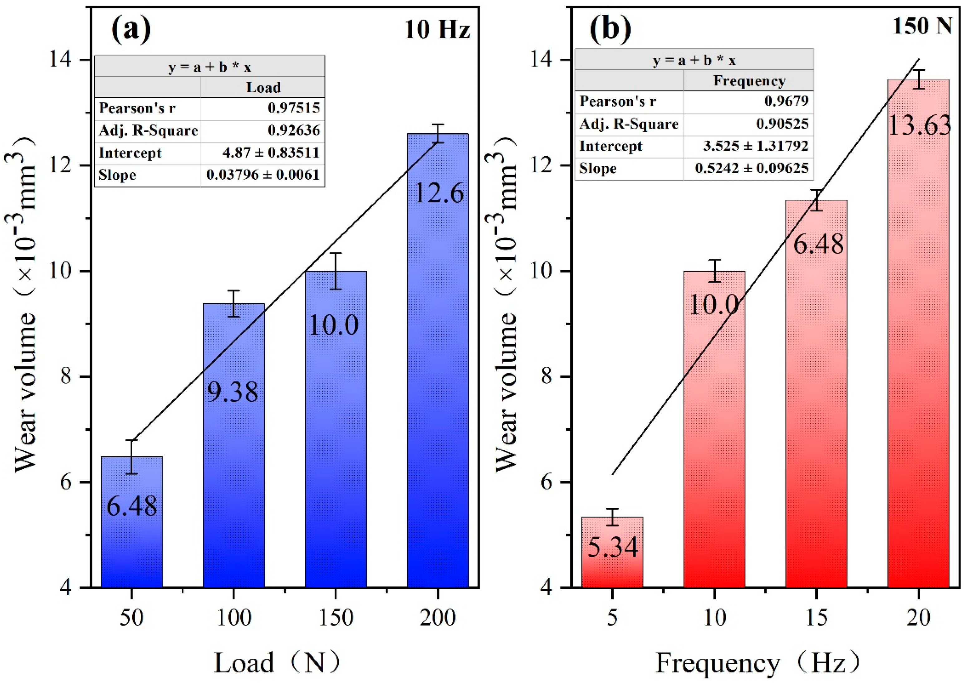
3.4.2. Wear Volume Loss
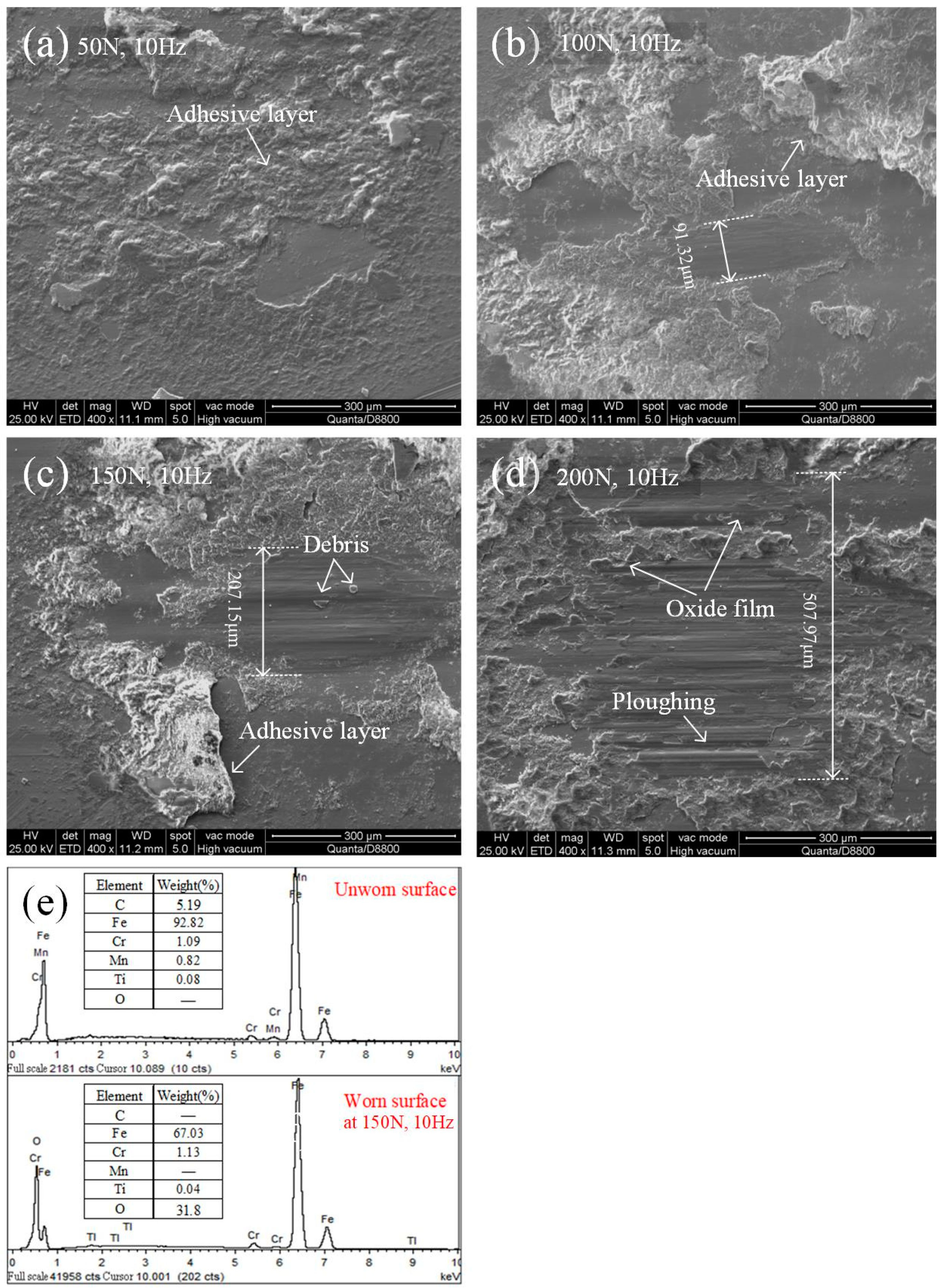
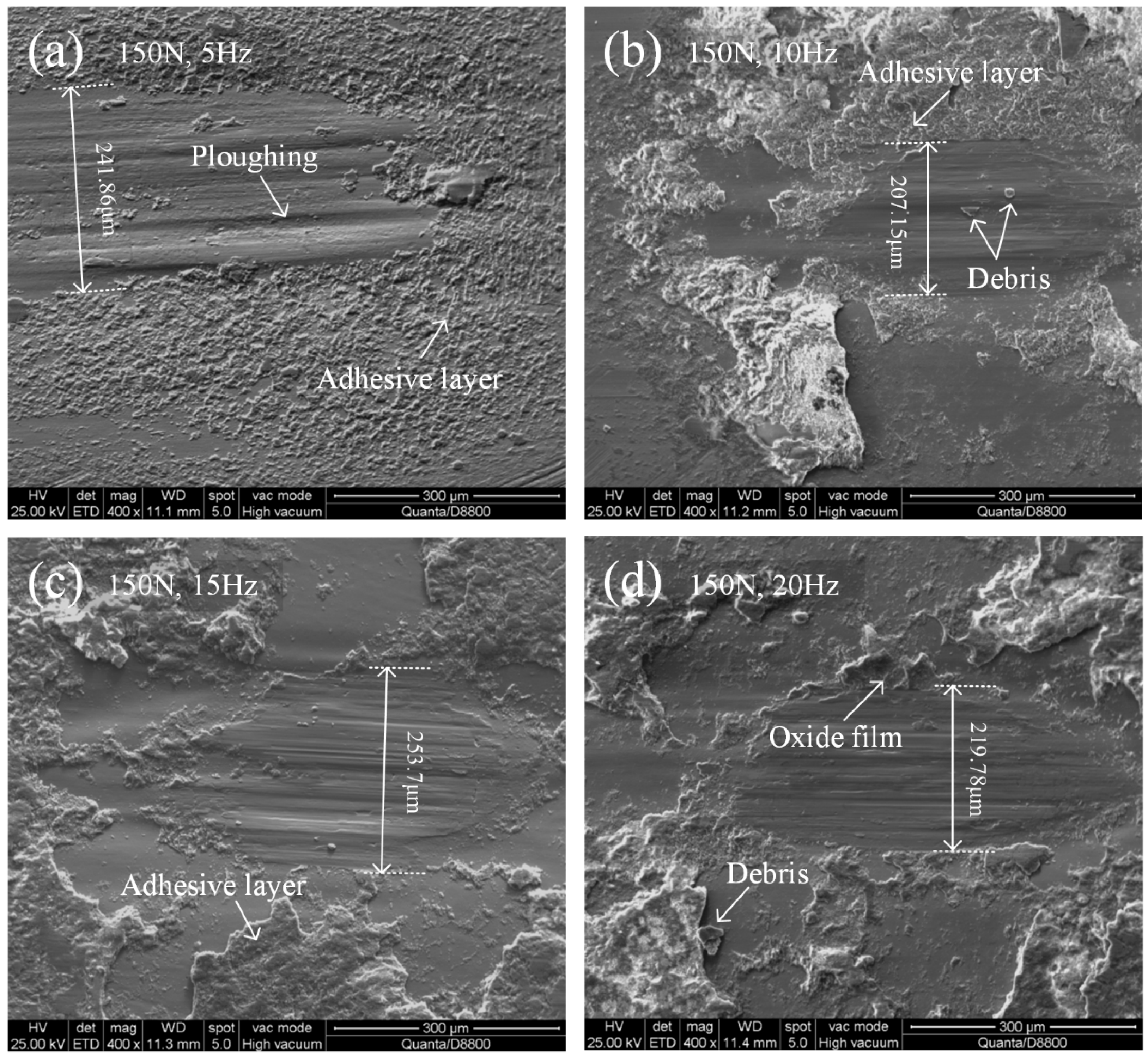
3.4.3. Variation of Wear Mechanism
4. Conclusions
- (1)
- After carburizing, the microstructure of 20CrMnTi steel was changed from a ferrite martensite structure to acicular martensite and a cementite structure, and the effective hardened thickness of carburized layer was about 1.2 mm. The coefficient of friction of carburized specimens was lower than that of virgin state and quenched state, and the wear volume loss of the specimens can be reduced by 46.5% and 72.1%, respectively, compared with virgin and quenched states.
- (2)
- The wear mechanisms of the specimen at virgin state are primarily abrasive wear and adhesive wear. The wear mechanisms of the specimen surface after quenching are similar, but accompanied by slight oxidative wear. Carburizing treatment increases the ratio of surface abrasive wear and oxidative wear, but fatigue wear is significantly inhibited.
- (3)
- When the load was increased from 50 to 100 N, the surface wear mechanism of the specimens indicated that the degree of adhesive wear gradually increased, and some oxidative wear were observed. With the load was increased from 150 to 200 N, it gradually turned into a variety of mixed mechanisms dominated by abrasive wear, and the oxidative wear increased with the increase of load.
- (4)
- With the increase of reciprocating frequency, the surface wear mechanisms of the specimens are basically similar, which are mainly composed of adhesive wear and abrasive wear. Slight fatigue wear and more severe oxidative wear were observed at only 5 and 20 Hz, respectively.
Author Contributions
Funding
Conflicts of Interest
Nomenclature
| CoF | coefficient of friction |
| WVL/Vs | wear volume loss (mm3) |
| R | curvature radius of the worn surface (μm) |
| ds | length of the wear scar in the fretting direction (μm) |
| dq | width of the wear scar perpendicular to the fretting direction (μm) |
| h | depth of the wear scar (μm) |
References
- Pandey, A.P. Effects of High Temperature on the Microstructure of Automotive Engine Valves. Int. J. Eng. Res. Appl. 2014, 4, 122–126. [Google Scholar]
- Flett, J.; Bone, G.M. Fault detection and diagnosis of diesel engine valve trains. Mech. Syst. Sig. Process. 2015, 72–73, 316–327. [Google Scholar] [CrossRef]
- Wang, Y. Introduction to engine valvetrains; SAE: New York, NY, USA, 2007. [Google Scholar]
- Ajayi, O.O.; Alzoubi, M.F.; Erdemir, A.; Fenske, G.R. Effect of Carbon Coating on Scuffing Performance in Diesel Fuels. Tribol. T. 2001, 44, 298–304. [Google Scholar] [CrossRef]
- Xu, X.L.; Gao, Y.; Yu, Z. Fatigue fracture of a truck diesel engine rocker-bracket. J. Fail. Anal. Prev. 2013, 13, 340–345. [Google Scholar] [CrossRef]
- Lawes, S.; Hainsworth, S.V.; Fitzpatrick, M.E. Impact wear testing of diamond-like carbon films for engine valve-tappet surfaces. Wear 2010, 268, 1303–1308. [Google Scholar] [CrossRef]
- Johnston, S.V.; Hainsworth, S.V. Effect of DLC coatings on wear in automotive applications. Surf. Eng. 2005, 21, 67–71. [Google Scholar] [CrossRef]
- Gangopadhyay, A.; Sinha, K.; Uy, D.; McWatt, D.G.; Zdrodowski, R.J.; Simko, S.J. Friction, wear, and surface film formation characteristics of diamond-like carbon thin coating in valvetrain application. Tribol. T. 2010, 54, 104–114. [Google Scholar] [CrossRef]
- Kano, M. DLC coating technology applied to sliding parts of automotive engine. New Diamond Front. Carbon Technol. 2006, 16, 201–210. [Google Scholar]
- Lai, F.; Qu, S.; Lewis, R.; Slatter, T.; Fu, W.; Li, X. The influence of ultrasonic surface rolling on the fatigue and wear properties of 23-8N engine valve steel. Int. J. Fatigue 2019, 125, 299–313. [Google Scholar] [CrossRef]
- Gangopadhyay, A.; McWatt, D.G. The effect of novel surface textures on tappet shims on valvetrain friction and wear. Tribol. T. 2008, 51, 221–230. [Google Scholar] [CrossRef]
- Lipiński, D.; Ratajski, J. Modeling of Microhardness Profile in Nitriding Processes Using Artificial Neural Network. In Advanced Intelligent Computing Theories and Applications. With Aspects of Artificial Intelligence; Springer: Berlin, Heidelberg, Germany, 2007; Volume 4682, pp. 245–252. [Google Scholar]
- Pellizzari, M.; Molinari, A.; Straffelini, G. Thermal fatigue resistance of gas and plasma nitrided 41CrAlMo7 steel. Mat. Sci. Eng. A 2003, 352, 186–194. [Google Scholar] [CrossRef]
- Han, D.; Hong, W.; Choi, H.S.; Lee, J.J. Inductively coupled plasma nitriding of chromium electroplated AISI 316L stainless steel for PEMFC bipolar plate. Int. J. Hydrogen Energy 2009, 34, 2387–2395. [Google Scholar] [CrossRef]
- Xia, Q.; Xiao, Q.; Cheng, C.; Zhao, D. Analyze and test of the abnormal wear between the cam and rocker arm. Vehicle Engine 2008, s1, 136–139. [Google Scholar]
- Guo, H.; Zhuo, B.; Peng, J.; Lin, G. Lubricating study of valve-valve guide in engine. Chin. J. Mech. Eng.-En. 2002, 38, 96–101. [Google Scholar] [CrossRef]
- Qi, L.; Zhao, L.; Ma, X.; Cui, H.; Zheng, W.; Lu, Y. Design and test of 3GY-1920 wide-swath type weeding-cultivating machine for paddy. Trans. Chin. Soc. Agric. Eng. 2017, 33, 47–55. [Google Scholar]
- Rong, L.; Lunjun, C.; Ming, S.; Qi, Z.; Yong, L. Study on Friction and Wear Characteristics of Aluminum Alloy Hydraulic Valve Body and Its Antiwear Mechanism. Arch. Foundry Eng. 2017, 17, 207–215. [Google Scholar] [CrossRef][Green Version]
- Shein, I.R.; Medvedeva, N.I.; Ivanovskii, A.L. Electronic structure and magnetic properties of Fe3C with 3d and 4d impurities. Physica. Status. Solidi. B 2007, 244, 1971–1981. [Google Scholar] [CrossRef]
- Medvedeva, N.I.; Kar Kina, L.E.; Ivanovskiĭ, A.L. Effect of chromium on the electronic structure of the cementite Fe 3 C. Phys. Solid State 2006, 48, 15–19. [Google Scholar] [CrossRef]
- Coronado, J.J. Abrasive size effect on friction coefficient of AISI 1045 steel and 6061-T6 aluminium alloy in two-body abrasive wear. Tribol. Lett. 60 2015, 40. [Google Scholar] [CrossRef]
- Ghaffarian, H.; Taheri, A.K.; Ryu, S.; Kang, K. Nanoindentation study of cementite size and temperature effects in nanocomposite pearlite: A molecular dynamics simulation. Curr. Appl. Phys. 2016, 16, 1015–1025. [Google Scholar] [CrossRef]
- Wong, T.; Kim, W.; Kwon, P. Experimental support for a model-based prediction of tool wear. Wear 2004, 257, 790–798. [Google Scholar] [CrossRef]
- Sakai, M. Energy principle of the indentation-induced inelastic surface deformation and hardness of brittle materials. Acta Metall. Mater. 1993, 41, 1751–1758. [Google Scholar] [CrossRef]
- Diomidis, N.; Mischler, S. Third body effects on friction and wear during fretting of steel contacts. Tribol. Int. 2010, 44, 1452–1460. [Google Scholar] [CrossRef]
- Amiriyan, M.; Blais, C.; Savoie, S.; Schulz, R.; Gariépy, M.; Alamdari, H. Tribo-Mechanical Properties of HVOF Deposited Fe3Al Coatings Reinforced with TiB2 Particles for Wear-Resistant Applications. Materials 2016, 9, 117. [Google Scholar] [CrossRef]
- Jiang, S.; Wang, H.; Wu, Y.; Liu, X.; Chen, H.; Yao, M.; Gault, B.; Ponge, D.; Raabe, D.; Hirata, A. Ultrastrong steel via minimal lattice misfit and high-density nanoprecipitation. Nature 2017, 544, 460–464. [Google Scholar] [CrossRef]
- Masoumi, M.; Sinatora, A.; Goldenstein, H. Role of microstructure and crystallographic orientation in fatigue crack failure analysis of a heavy haul railway rail. Eng. Fail. Anal. 2019, 96, 320–329. [Google Scholar] [CrossRef]
- Xianglin, D. The effect of quench hardening on the fretting wear of medium carbon steel. Wear 1988, 123, 77–85. [Google Scholar] [CrossRef]
- Zum Gahr, K.; Doane, D.V. Optimizing fracture toughness and abrasion resistance in white cast irons. Metall. Trans. A 1980, 11, 613–620. [Google Scholar] [CrossRef]
- Sevim, I.; Eryurek, I.B. Effect of fracture toughness on abrasive wear resistance of steels. Mater. Des. 2006, 27, 911–919. [Google Scholar] [CrossRef]
- Li, C.S.; Liu, X.H.; Wang, G.D.; Yang, G. Experimental investigation on thermal wear of high speed steel rolls in hot strip rolling. Mater. Sci. Technol. 2002, 18, 1581–1584. [Google Scholar] [CrossRef]
- Zhao, M.; Huang, X.; Atrens, A. Role of second phase cementite and martensite particles on strength and strain hardening in a plain C-Mn steel. Mat. Sci. Eng. A. 2012, 549, 222–227. [Google Scholar] [CrossRef]
- Lim, C.Y.H.; Lim, S.C.; Gupta, M. Wear behaviour of SiC p -reinforced magnesium matrix composites. Wear 2003, 255, 629–637. [Google Scholar] [CrossRef]
- Chen, Y.; Huang, P. Experiment study on adhesion between rough surfaces. J. Tribol. 2016, 36, 269–275. [Google Scholar]
- Carey, J.P.; Craig, M.; Kerstein, R.B.; Radke, J. Determining a relationship between applied occlusal load and articulating paper mark area. The Open Dentistry J. 2007, 1, 1–7. [Google Scholar] [CrossRef]
- Wen, S.; Huang, P. Principles of tribology; Wiley Online Library: Hoboken, NJ, USA, 2012. [Google Scholar]
- Wang, S.Q.; Wei, M.X.; Wang, F.; Zhao, Y.T. Transition of elevated-temperature wear mechanisms and the oxidative delamination wear in hot-working die steels. Tribol. Int. 2010, 43, 577–584. [Google Scholar] [CrossRef]
- Kalin, M.; Vižintin, J. High temperature phase transformations under fretting conditions. Wear 2001, 249, 171–181. [Google Scholar] [CrossRef]
- Zhang, Y.S.; Han, Z.; Lu, K. Fretting wear behavior of nanocrystalline surface layer of copper under dry condition. Wear 2008, 265, 396–401. [Google Scholar] [CrossRef]
- Zhang, N.; Zhang, J.; Lu, L.; Zhang, M.; Zeng, D.; Song, Q. Wear and friction behavior of austempered ductile iron as railway wheel material. Mater. Des. 2016, 89, 815–822. [Google Scholar] [CrossRef]
- Chen, Y.K.; Han, L.; Chrysanthou, A.; O’Sullivan, J.M. Fretting wear in self-piercing riveted aluminium alloy sheet. Wear 2003, 255, 1463–1470. [Google Scholar] [CrossRef]
- Berriche, Y.; Vallayer, J.; Trabelsi, R.; Treheux, D. Severe wear mechanisms in Al2O3–AlON ceramic composites. J. Eur. Ceram. Soc. 2000, 20, 1311–1318. [Google Scholar] [CrossRef]
- Yun, J.Y.; Park, M.C.; Shin, G.S.; Heo, J.H.; Kim, D.I.; Kim, S.J. Effects of amplitude and frequency on the wear mode change of Inconel 690 SG tube mated with SUS 409. Wear 2014, 313, 83–88. [Google Scholar] [CrossRef]
- Huang, X.; Neu, R.W. High-load fretting of Ti–6Al–4V interfaces in point contact. Wear 2008, 265, 971–978. [Google Scholar] [CrossRef]
- Warmuth, A.R.; Shipway, P.H.; Sun, W. Fretting wear mapping: The influence of contact geometry and frequency on debris formation and ejection for a steel-on-steel pair. Proc. R. Soc. A 2015, 471, 471. [Google Scholar] [CrossRef]


| C | Si | Mn | P | S | Cr | Ti | Fe |
|---|---|---|---|---|---|---|---|
| 0.225 | 0.244 | 0.810 | ≤0.05 | ≤0.05 | 1.044 | 0.065 | Balance |
| Load (N) | Stroke (μm) | Frequency (Hz) | Time (s) |
|---|---|---|---|
| 30 | 200 | 10 | 1800 |
| Variable Index | Test Parameter | |||
|---|---|---|---|---|
| Load (N) | Time (s) | Frequency (Hz) | Stroke (μm) | |
| Load | 50, 100, 150, 200 | 1800 | 10 | 200 |
| Frequency | 150 | 1800 | 5, 10, 15, 20 | 200 |
© 2020 by the authors. Licensee MDPI, Basel, Switzerland. This article is an open access article distributed under the terms and conditions of the Creative Commons Attribution (CC BY) license (http://creativecommons.org/licenses/by/4.0/).
Share and Cite
Tang, J.; Hu, X.; Lai, F.; Guo, X.; Qu, S.; He, R.; Qin, S.; Li, J. Evolution of Fretting Wear Behaviors and Mechanisms of 20CrMnTi Steel after Carburizing. Metals 2020, 10, 179. https://doi.org/10.3390/met10020179
Tang J, Hu X, Lai F, Guo X, Qu S, He R, Qin S, Li J. Evolution of Fretting Wear Behaviors and Mechanisms of 20CrMnTi Steel after Carburizing. Metals. 2020; 10(2):179. https://doi.org/10.3390/met10020179
Chicago/Turabian StyleTang, Jinchi, Xiongfeng Hu, Fuqiang Lai, Xiaolong Guo, Shengguan Qu, Ruiliang He, Shunshun Qin, and Jianwen Li. 2020. "Evolution of Fretting Wear Behaviors and Mechanisms of 20CrMnTi Steel after Carburizing" Metals 10, no. 2: 179. https://doi.org/10.3390/met10020179
APA StyleTang, J., Hu, X., Lai, F., Guo, X., Qu, S., He, R., Qin, S., & Li, J. (2020). Evolution of Fretting Wear Behaviors and Mechanisms of 20CrMnTi Steel after Carburizing. Metals, 10(2), 179. https://doi.org/10.3390/met10020179