Article

Microstructure and Wear Behavior of In Situ ZA27/TiB2 Composites

1
School of Materials Science and Engineering, Jiangsu University, Zhenjiang 212013, China
2
Key Laboratory of Solidification Control and Digital Preparation Technology (Liaoning Province), School of Materials Science and Engineering, Dalian University of Technology, Dalian 116024, China
*
Authors to whom correspondence should be addressed.
Metals 2020, 10(12), 1663; https://doi.org/10.3390/met10121663
Submission received: 11 October 2020 / Revised: 6 December 2020 / Accepted: 8 December 2020 / Published: 11 December 2020

Abstract

:
In situ ZA27/TiB2 composites were synthesized successfully by diluting the in situ Al/TiB2 composite, which was used as a master alloy. The microstructure and hardness of the developed in situ composites have been investigated. Results have shown that TiB2 particles distribute uniformly through the matrix and significantly refine the matrix grain. The hardness of the composites was higher than that of the matrix alloy and increased with the increasing TiB2 content. The dry sliding wear behavior under heavy loads and high rotation speed were studied in detail by using a pin-on-disc wear tester at room temperature. The results revealed that the wear resistance of the composites increased monotonically with the increase in the TiB2 content. The composites had a lower coefficient of friction, friction temperature, wear rate, and specific wear rate especially under high loads when compared with the matrix alloy. An increase in the applied load increased the wear severity by changing the wear mechanism from abrasion and oxidation to adhesive wear. The composites possess better adhesive wear resistance properties compared with the matrix, which shows obvious adhesive wear as the load increased to 36 N, while the ZA27/3.0% TiB2 composite did not show adhesive wear until the load increased to 54 N.

1. Introduction

Zinc alloys are characterized by high strength, good tribological properties, high damping, non-magnetism, low melting temperatures, and excellent formability [1,2,3]. It can be used not only in the production of structural parts, but also in the manufacturing of wear-resistant parts [4,5]. Nevertheless, zinc alloys suffer from a drastic deterioration in their properties when the operating temperature is above 100 °C, and cannot be used effectively under high speed working conditions [6,7], especially in the dry or non-hydrodynamic friction regime. Therefore, further improving the tribological characteristics of zinc alloys to substitute traditional high-melting bearing alloys, such as bronzes and iron alloy, can help simplify the fabrication process, decrease energy consumption, and reduce the manufacturing cost in case of cast machine components. In recent years, reinforcing with second phase particles has been verified to be an important way to further improve the strength and wear resistance of zinc alloys [2,8,9]. A conventional practice to prepare zinc-based composites is the ex situ method, which involves the addition of externally synthesized particles, for instance, SiC [10,11], Al2O3 [12], ZrO2 [13], graphite [14], and TiO2 [15], etc. into matrix alloys. However, owing to the surface contamination of the reinforcements and poor particle-matrix wettability, various problems such as particles segregation, poor adhesion at the interface, and inferior thermodynamically instability of the reinforcement frequently arise in the fabricating process [8,16,17,18].
Recently, in situ synthesis techniques have been developed to produce MMC [17,19,20,21]. Since the formation and growth of reinforcement take place within the matrix, the in situ preparation of composites provides advantages including uniform distribution of finer particles, excellent bond at the interface, and thermodynamically stable reinforcements that overwhelm the conventional ex situ processes, yielding better mechanical and tribological properties [22,23]. Although various in situ techniques have been used to fabricate aluminum [17,24], magnesium [25], copper [26], and iron [27] matrix composites, relatively fewer studies have been reported regarding the fabrication and properties of zinc-based in situ composites. Therefore, the preparation of zinc-based in situ composites is of great significance to expand the application field of zinc alloys and improve the use efficiency of zinc resources.
In our previous study, the high-quality Al/TiB2 in situ composite had been fabricated [20], and was used as a master alloy to refine ZA27, furthermore, the influence of TiB2 on solidification dynamics of ZA27 alloy has been investigated in detail by synchrotron radiation microradiography [28]. ZA27 is a typical zinc alloy and has been considered for a number of commercial applications due to the good mechanical, machinability [29,30], and its nominal composition is listed in Table 1. Although zinc alloys are usually used in lubrication conditions, they may be short of oil temporarily during the mechanical start-up stage or when occasional accidents take place. As a result, the components should work under a boundary lubrication or non-lubrication condition, which is easy to cause the danger of “bearing burning” or “journal sticking”. Therefore, it is necessary to consider the dry friction performance of zinc based in situ composites. In the present study, ZA27/TiB2 in situ composites were fabricated using the Al/TiB2 composite as the master alloy, and their dry sliding wear performance under relative heavy loads and high rotation speed, which is not applicable for traditional zinc alloys [7,31], were investigated in detail to evaluate the enhancement of TiB2 particles to wear resistance of the matrix alloy. Additionally, the main wear mechanisms were also discussed based on the experimental observation.

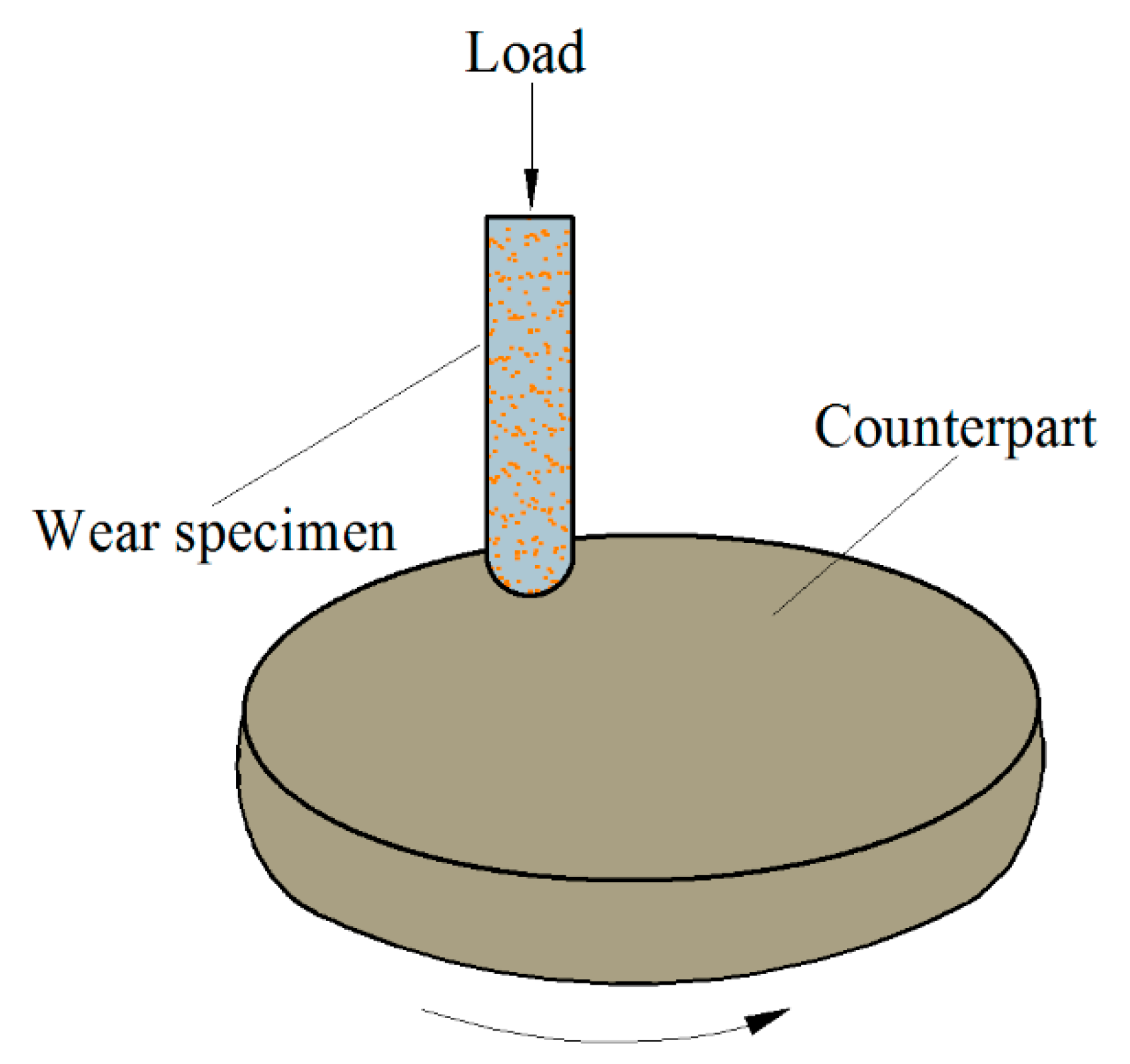
2. Experimental Procedure

ZA27/TiB2 in situ composites with different weight percentages (0.6, 1.8, and 3.0) of TiB2 were fabricated by diluting the in situ Al/TiB2 composite. The raw materials were commercial pure aluminum, 0.5 mm thickness Cu foil, pure magnesium, pure zinc, and the Al/10% TiB2 composite prepared using our previously developed mechanical stirring technique [20]. Firstly, the Al/10% TiB2 composite and pure Al were melted at 720 °C in a resistance furnace (Shiyan Electric Furnace Ltd., Shanghai, China), while pure zinc was melted at 450 °C in another resistance furnace. When the aluminum melt reached the setting temperature, Cu and Mg were added and melted. Then, the aluminum melt and zinc melt were mixed rapidly and transferred into a stirring furnace at 610 °C and held for 30 min. After that, the melt was stirred for 2 min at 120 rpm by a preheated graphite stirring paddle, and refined using high-purity argon gas, and then poured into a stainless steel mold preheated at 100 °C after slagging off.
The phase identification of the composite was performed by an X-ray diffractometer (PANalytical, Almelo, Netherlands) using Cu Kα radiation and operated at 40 kV and 40 mA. For the microstructure analysis, the specimens were polished and etched with Keller’s reagent, and then observed by a field emission scanning electron micrograph (SEM) operated at 15 kV and equipped with an energy dispersive spectrometer (EDS). The high resolution transmission electron microscope (TEM) analysis was carried out using a JEOL 2100 TEM (200 keV incident beam voltage, JEOL Ltd., Tokyo, Japan).
The hardness tests of the composites were carried out using a Brinell hardness tester (Shidai Ltd, Jinan, China) with an indenter diameter of 10 mm. The selected experimental force was 1000 kgf, and the holding time was 30 s. Each sample was measured three times, and the average value of the three results was determined as the hardness of the material.
The dry sliding wear resistance of the composites was carried out using the CFT-I universal friction and wear testing machine (ZKKH Ltd., Lanzhou, China) controlled by a microcomputer. Considering that zinc alloys are conventionally used to produce sliding bearings, therefore, the pin-on-disc module with sliding and rotating features was used. Figure 1 is the schematic diagram of the wear experiment. The pin-like specimens of Φ4.8 mm × 12.7 mm were made by the fabricated composites, while the counterpart discs with an outer diameter of 40 mm and a height of 10 mm were made from ASTM E52100 bearing steel, which is the most widely used bearing alloy and has an excellent wear resistance. Therefore, the composites couple with the bearing steel is much similar to the real service condition of the zinc alloys.
Since traditional zinc alloys cannot be used under high speed working conditions owing to their poor high temperature performance [31,32], a relative high rotation speed (important limiting factor for the matrix alloys) and different loads were chosen in the present study to accurately evaluate the enhancement of TiB2 to the wear resistance of the matrix alloys. The experimental speed was fixed at a high speed of 600 rpm, the diameter of friction track was 2 cm, and the wear time was 1 h. In order to evaluate the wear resistance of the composite objectively, the wear experiments were carried out under three different loads of 18, 36, and 54 N, the corresponding contact stress was 1, 2, and 3 MPa, respectively, which coupled with the high rotation speed form a high speed and heavy load situation [33]. As a result, the friction pair will release lots of heat, which is helpful to reveal the wear resistance of the material under severe conditions.
The changes of the coefficient of friction (COF) during the experiment were recorded by the computer in real time (once per second). A thermocouple connected with a Graphtec GL220 paperless data logger (Graphtec Co., Yokohama, Japan) was attached to the sample surface to record the temperature change of the sample during the experiment. The temperature acquisition frequency was 2 times per second. Before and after the experiment, the samples were put into alcohol for ultrasonic cleaning for 30 min, then dried and weighed to determine the wear mass loss. The wear rate can be obtained by dividing the mass loss by the material density and sliding distance, i.e., the volume loss per unit sliding distance. In order to improve the accuracy of the measurement, three experiments were carried out under each set of experimental parameters, and the average value of three results was taken as the final representative result.

3. Results and Discussion

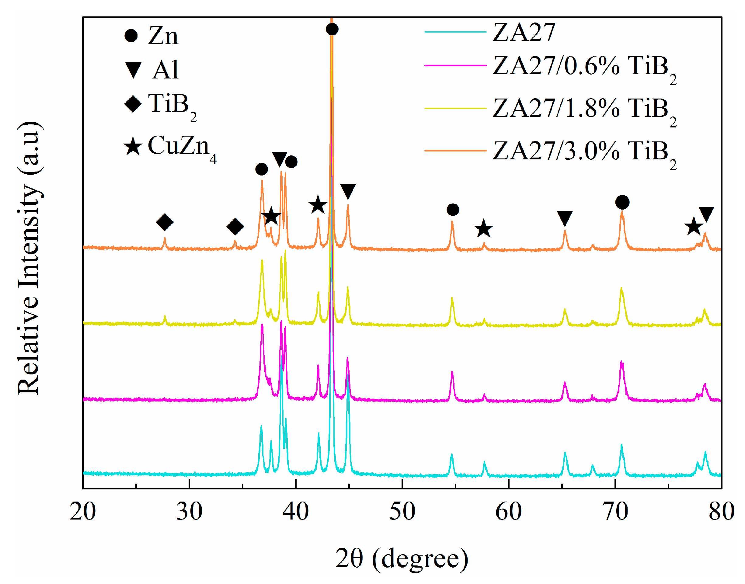
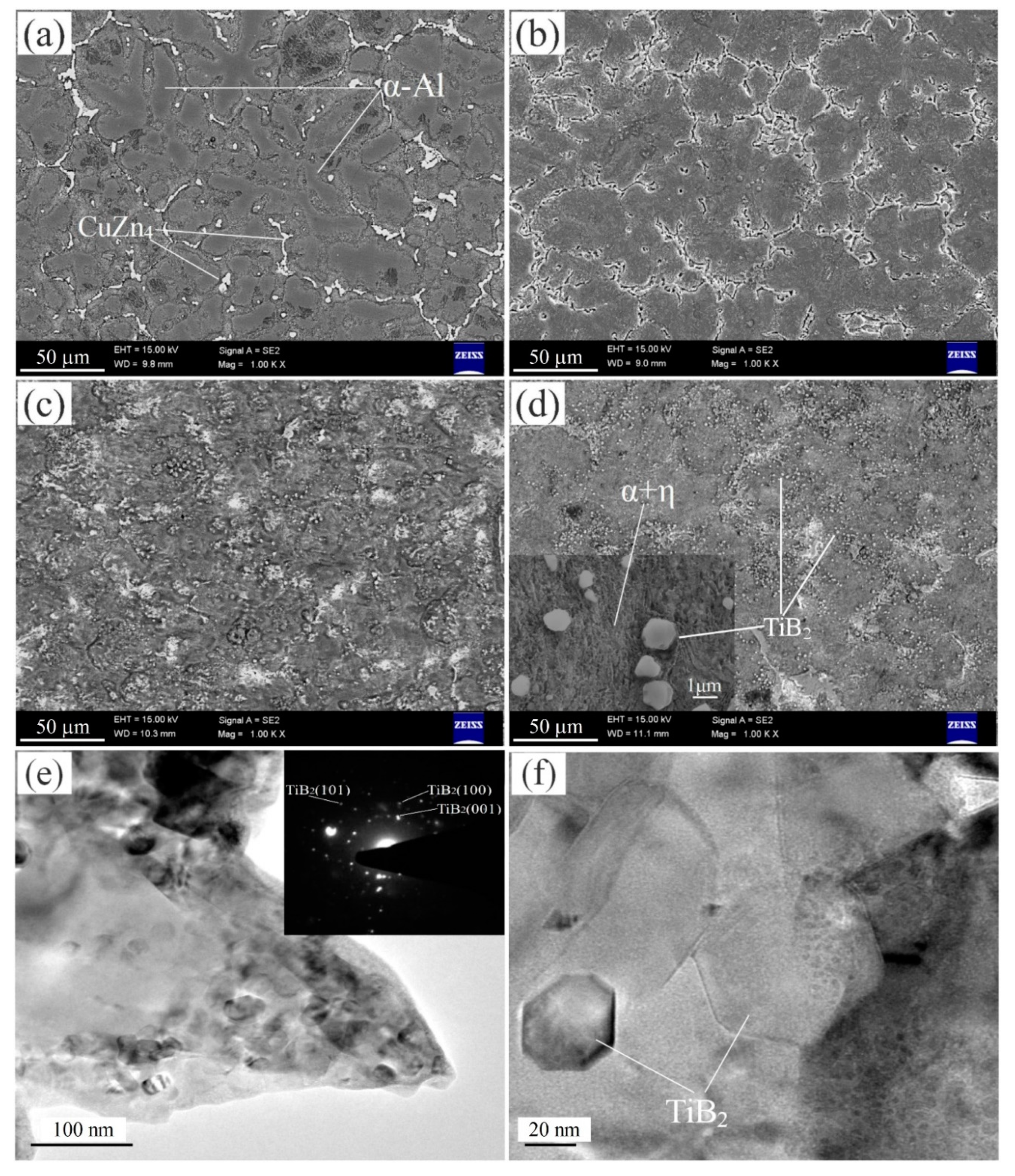
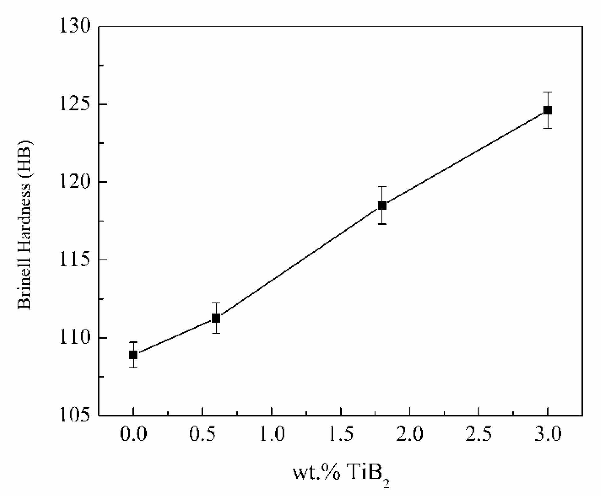
3.1. Microstructure and Hardness Characterization

The XRD spectrum of ZA27/TiB2 composites is shown in Figure 2. It can be seen that the composite mainly contains α-Al, η-Zn, ε-CuZn4, and TiB2. The intensity of the TiB2 diffraction peak increases with the increasing particle content, indicating that the TiB2 particle content in the composites can be controlled. No obvious brittle intermetallic compounds such as TiAl3 and AlB2, as well as Al2O3, ZnO, and other harmful phases can be detected, confirming the feasibility of the preparation technology of the composites.
Figure 3a–d shows the SEM images of the matrix alloy and the fabricated composites. As observed in Figure 3a, the structure of the matrix alloy is mainly composed of coarse α-Al dendrites, and the inter-dendritic regions are mainly occupied by non-equilibrium eutectic and intermetallic CuZn4. Due to the eutectoid reaction at 275 °C, α-Al dendrites transform into lamellar eutectoids composed of α-Al and η-Zn (illustrated in Figure 3d). Compared with the matrix, the dendrite branches in the composites decrease and the grains are obviously refined. When the TiB2 content increases from 0 to 3%, the average grain size of α-Al decreases from 205.4 to 52.3 μm. The corresponding grain refinement mechanisms have been revealed in our previous work [28]. The TiB2 particles distribute uniformly in the matrix, and there is no obvious particle aggregation. This is mainly due to the in situ fabrication, which improves the wettability between the matrix and the reinforcement. In addition, owing to the small density difference between the particles (4.5 g/cm3) and melt (≈4.0 g/cm3), the particles can be suspended in the melt for a long time [19]. During the solidification process of the composites, the suspended particles are engulfed by the solidification front, and evenly distributed in the solidification structure. Such particle distribution can reduce the stress concentration, which is very important to the improvement of the mechanical properties of the composites.
TEM micrographs and the selected area electron diffraction pattern of the composites are presented in Figure 3e,f. It is evident that a number of nanoparticles (20~100 nm) are dispersed in the matrix. Due to the small size of the particles, there are many particles in the selected area, and the diffraction pattern is polycrystalline. It can be seen that the interface between the TiB2 particles and matrix alloy is straight and clean, and no obvious holes, cracks, residual fluorine salts, and adverse interface reaction products can be found, indicating that the particles are well-bonded to the matrix.
The hardness of the matrix alloy and ZA27/TiB2 composites is shown in Figure 4. It is obvious that the hardness of the composites is significantly higher than that of the matrix and increases gradually with the increasing particle content. When the particle content is 0.6%, 1.8%, and 3.0%, the hardness of the composites is 2.2%, 8.9%, and 14.4% higher than that of the matrix, respectively. As we all know, the hardness is a measurement of the material’s ability to resist plastic deformation. Therefore, the above phenomenon shows that the ZA27/TiB2 composites have a stronger ability to resist plastic deformation compared to the matrix alloy.

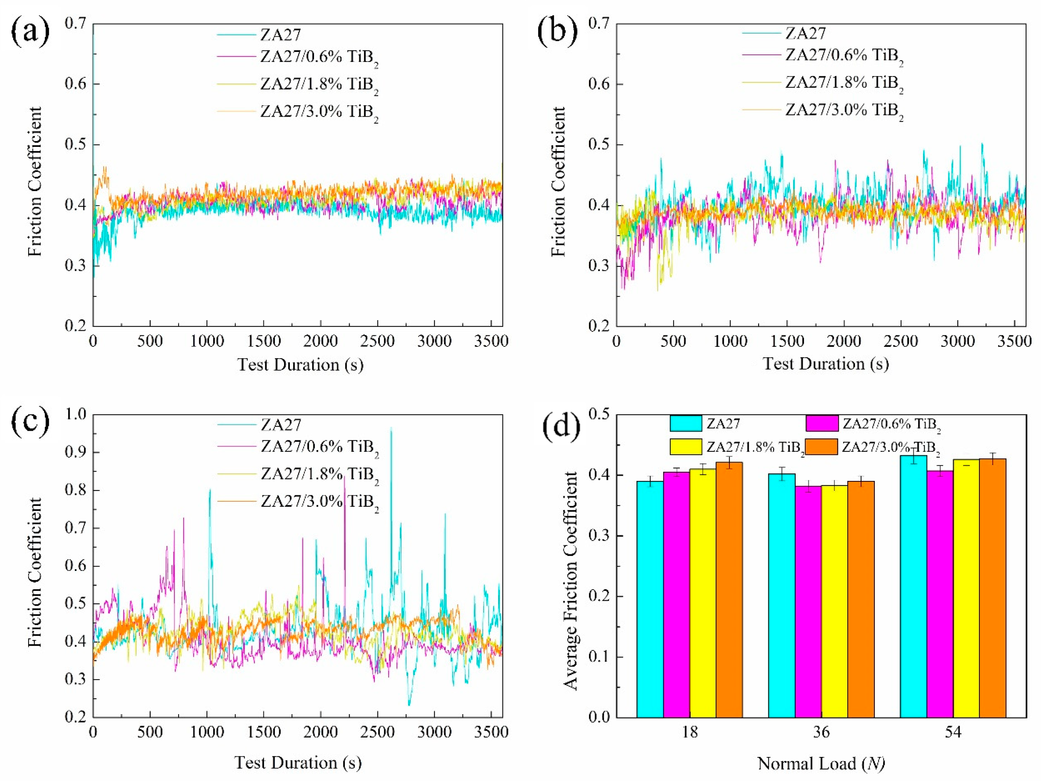
3.2. Coefficient of Friction

The change of coefficient of friction (COF) with time and the average coefficient under different loads are shown in Figure 5. It can be seen that, for all the loads, the COF increases rapidly with time after the experiment begins, and then the curve gradually stabilizes. These two stages correspond to the initial running-in and the stable wear stage, respectively. Since the apex of the sample is a spherical cap, in addition, the surface of the sample and the counterpart is not completely smooth, but has many tiny surface protrusions. The contact between the sample and counterpart thus occurs at only a few highly protruding asperities and induces high contact stress at the beginning of the wear [19,34]. As the test proceeds, the apex of the sample and the asperities are gradually worn down, and the contact area between the dual parts increases gradually and tends to be stable, so called the running-in stage [23], which is an adaptive process of friction pair, and its duration is related to the relative sliding speed and the load. It can be found that with the load increasing from 18 to 54 N, the running-in stage gradually extends from 3 to 5 min, while the particle content has no obvious influence on the duration.
It can be seen from Figure 5a that the COF of the matrix and composites show a little fluctuation when the load is 18 N, indicating that the wear process is relatively stable at this time. When the load increases to 36 N (Figure 5b), the COF of the matrix and ZA27/0.6% TiB2 composite fluctuates greatly. However, for the other two composites with a high particle content, the COF is still stable, indicating that they can smooth run without obvious wear mechanism changes. Compared with the load of 18 N, the COF of the two composites decreases slightly, which is consistent with a large number of reports [35,36]. In the abrasive wear, the fine wear debris produced under the high load has a certain degree of solid lubrication, the COF thus decreases with the increase of the load [23,37,38]. When the load increased to 54 N (Figure 5c), the COF of the matrix alloy increases greatly and fluctuates violently, and shows a series of sharp peaks, some of which are close to 1, indicating that large surface protrusion, coarse debris, or adhesive junctions result in the rapid increase of the friction force. After a period of time, these protrusion, debris, or junctions are worn out and pushed out of the mating surfaces due to the mechanical rolling and centrifugal force, and the COF drops sharply, thus forming a sharp peak in the curve. At the end of the wear test, sharp peaks appear intensively in the curve, which indicates that the wear resistance of the sample decreases significantly. However, the overall COF of the composites, especially ZA27/1.8% TiB2 and ZA27/3% TiB2, increases slightly, and the fluctuation range is within ±0.1, and the wear process is generally stable.
Figure 5d shows the average COF of the matrix alloy and composites. It can be seen that the average COF of the composites is lower than that of the matrix under all loads except for the 18 N load, confirming that the composites have a better anti-wear performance. The lower COF will generate less vibration and noise, reduce the energy consumption, and extend the service life of components and mechanical equipment. The slightly lower COF of the matrix alloy under the light load of 18 N may be due to the TiB2 particles protruding from the sample surface results in the increase of the surface roughness [39].

3.3. Sample Temperature
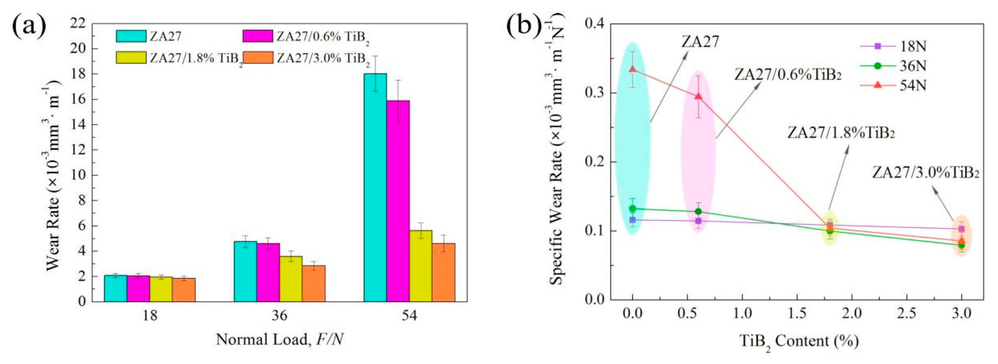
Temperature rising can significantly affect the material behavior and alter wear mechanism. Therefore, the variation of sample temperature during the testing has been monitored and analyzed. Figure 6 shows the change of the sample temperature of the matrix alloy and ZA27/3.0% TiB2 composite during the wear process. Similar to the COF curve, in the initial stage of wear (the running-in stage), the temperature curve increases rapidly. With the increase of the load, the slope of the initial increasing stage of the curve increases, indicating that the frictional heat increases with the increasing load. After the initial rise, the sample temperature shows different changing trends due to different loads and materials. When the load is 18 N, the temperature of the matrix alloy and composites decreases slowly, which is owing to the unstable wear and large amount of friction heat produced in the running-in stage, and as the test proceeds into the stable stage, the release rate of friction heat decreases, thus, the temperature drops slowly. When the load is increased to 36 N, the temperature of the matrix alloy increases obviously and fluctuates sharply with the peak value exceeding 80 °C. The temperature twists and increases gradually with the wear time, and the average value in the last 10 min of the experiment is about 78.6 °C, which is consistent with the change of the COF. Although the temperature of the composite increases to about 55 °C, the trend of the temperature change is still the same as that under the low load (18 N).
As the load increased to 54 N, the temperature of the matrix fluctuates more sharply with the maximum value of 116 °C, and the average temperature of the last 10 min is about 101.8 °C. Such high temperature will lead to the obvious softening of the alloy. The temperature trend of the composite starts to change at this time, namely, increases slowly and fluctuates slightly during the test process, indicating that a change probably takes place in the wear mechanism of the composites at this time. The average temperature of the last 10 min reaches 76.9 °C, which is significantly lower than that of the matrix alloy and will help maintain the composite strength.

3.4. Wear Rate

Figure 7a shows the wear rates of the matrix alloy and composites under different loads. It can be found that the wear rates increase with the increasing load and decrease with the increasing TiB2 content. For the load of 18 N, the wear rate of the matrix alloy is 1.13 times that of the ZA27/3%TiB2 composite, indicating that TiB2 particles have no significant contribution to the wear resistance under the low load. As the load increases to 36 N, the wear rates of all materials increases significantly, however, that of the matrix alloy increases by 128.0%, while that of the ZA27/3.0% TiB2 composite increases by 53.6%, the former is 1.67 times of the latter. As the load increases to 54 N, the wear rates of the matrix alloy and ZA27/0.6% TiB2 increase by 763.9% and 671.2% as compared with the condition of the 18 N load, while that of the composites containing 1.8% and 3.0% TiB2 increase by only 188.2% and 149.3%, respectively. In this case, the wear rate of the matrix alloy is 3.9 times higher than that of ZA27/3.0% TiB2. It can be found that with the increase of the load, the wear rate difference between the matrix and the composite gradually increases, indicating that the wear resistance of the composites under a high load is more prominent, this is quite different from the traditional ex situ composites [40,41], in which the wear resistance advantage reduces with the increase in the load applied.
Figure 7b shows the specific wear rate of the composites under different loads. The specific wear rate is the volume loss per unit sliding distance and load [37], thus reflecting the ability of the material to bear the wear load. It can be seen that the specific wear rate of the matrix alloy increases with the increasing of the load, especially when the load increases from 36 to 54 N, confirming that the wear resistance of the alloy declines obviously with the increase of the load, namely, the ability to resist a heavy load is inferior. However, for the composites with the TiB2 content of 1.8% and 3.0%, their specific wear rates under a heavy load (36 and 54 N) are even slightly lower than that under a low load, thus, providing sufficient evidence that the composites have an obvious wear resistance advantage, especially under a high load. This means that the introduction of TiB2 particles can break the limitation of the traditional zinc alloy to a certain extent, and improve the application potential of the alloy.

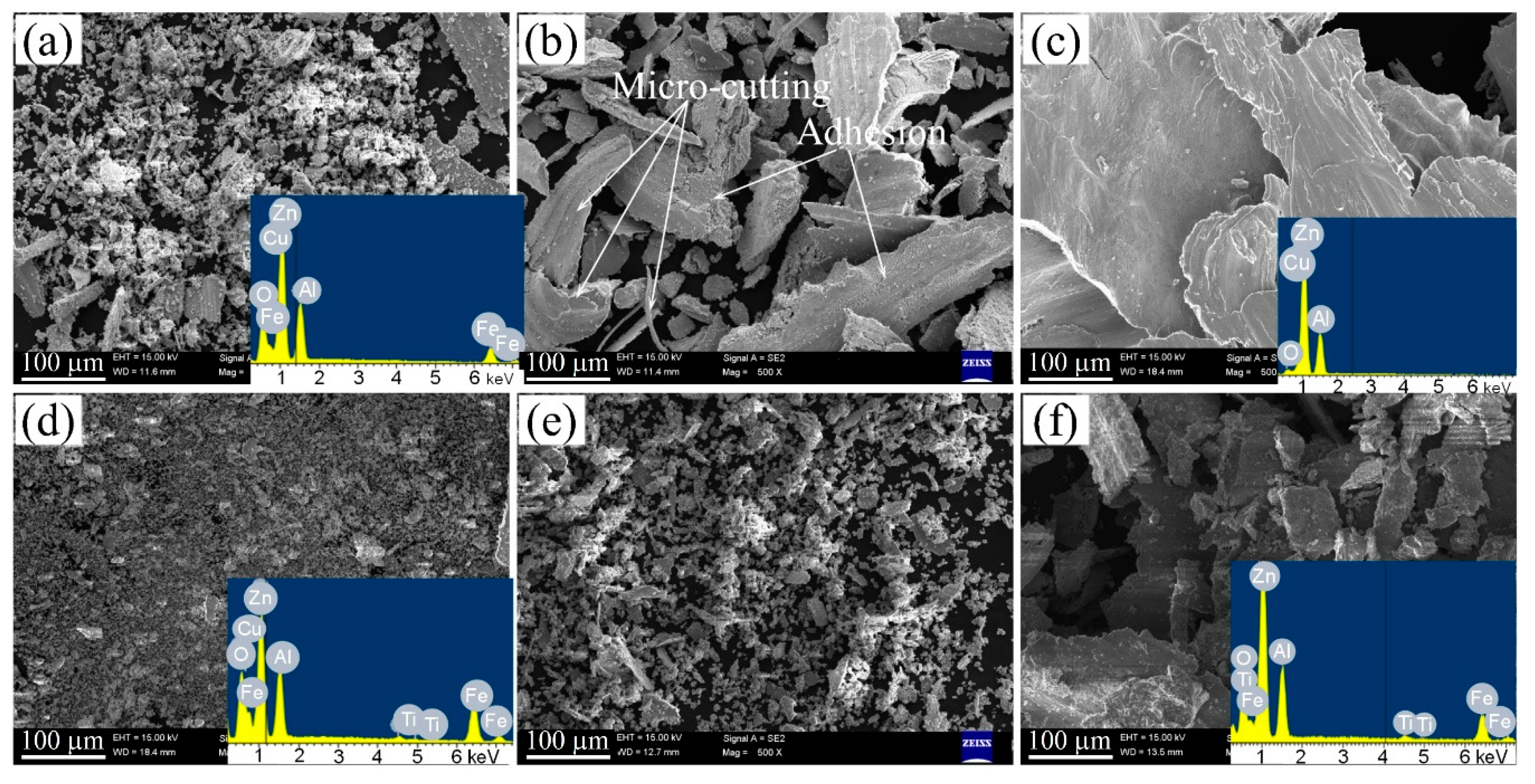
3.5. Wear Debris Morphology

In order to study the change of the wear debris under different loads and infer the wear mechanism, the counterparts together with the wear debris on their surface were photographed after the experiment (Figure 8), and the corresponding micro morphology and EDS analysis are shown in Figure 9. As shown in Figure 8, under the action of centrifugal force, the wear debris is distributed in a ring shape on the surface of the counterpart. As the load is 18 N, the wear debris of the matrix and composites is fine black powder. The EDS analysis in Figure 9a,d shows that the powder is mainly composed of tiny debris with a size less than 5 μm and some large strip debris, which is much smaller for the composites. The powder mainly contains Zn, Al, Fe, and O elements, and the atomic percentages of Fe are 18.3% and 17.7%, the atomic percentages of O are 42.2% and 43.1%, respectively, indicating that there are a lot of oxides in the debris, and the friction pair experiences oxidation wear in the wear test. Under the action of oxygen and friction heat, an oxide film is formed on the worn surfaces of both parts of the friction pair. Therefore, the two parts can contact each other by the oxide film. The size of the strip wear debris of the matrix alloy is slightly larger than that of the composite, which indicates that TiB2 particles can inhibit the surface abrading of the sample. When the load increases to 36 N, the wear debris of the matrix alloy turns to gray, increases obviously in the size, and contains some large-scale silvery white wear debris. The EDS test results show that the Fe content decreased to 10.4% and the oxygen content dropped to 29.3%, indicating that the oxide film on the surface has been damaged to a certain extent, and the probability of direct contact between the two parts of the friction pairs or between the alloy and abrasive particles increase, so that the “fresh” metal is directly grinded. However, the wear debris of the composite does not change significantly, the EDS results show that the oxygen content of the debris slightly decreases to 38.5% and the iron content increases to 18.4%.
As the load increases to 54 N, the wear debris of the matrix alloy tends to become much silvery with a flake-like main morphology. Most of the debris has a size greater than 0.5 mm. The debris mainly contains two elements, Zn and Al, and the percentage of oxygen atom further decreases to 12.4% (Figure 9c), indicating that the oxide film on the sample surface is completely damaged and serious material migration occurs. At the same time, the wear debris of the composite changes from black to taupe (Figure 9f), and contains some coarse silvery wear debris. Most of the wear debris is flake-like with a size in the range of 5–200 μm, and the composition is mainly Zn, Al, Fe, O, in which the atomic percentages of O and Fe are reduced to 31.9% and 13.7%, respectively, indicating that the oxide film is no longer an integrity.

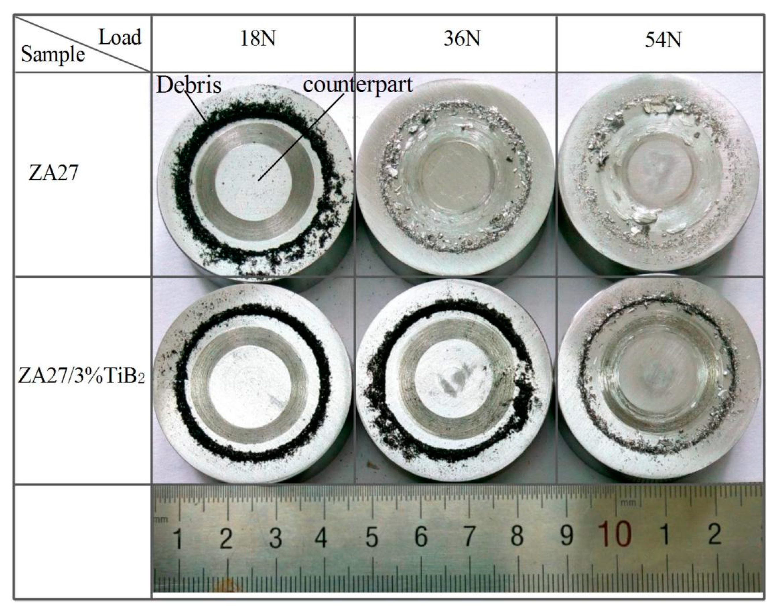
3.6. Worn Surface of the Counterpart

A comprehensive study of the wear requires a detailed investigation of the counterpart worn surface after the wear test. Figure 10 and Figure 11 are the macroscopic and SEM images of the counterpart surface with the debris removed. It can be seen that under a low load (18 N), the worn surfaces of all the counterparts are grayish brown. SEM shows that the worn surfaces are mainly shallow circular grooves with the width in the range of 20–55 μm (Figure 11a). The EDS analysis shows that the wear tracks of the counterparts mainly contain O, Zn, Al, Fe, and trace Ti, in which the O atom percentage is 46.1%. It is proven that with the participation of matrix alloy elements and oxygen, oxide forms on the surface of the counterparts. The local enlarged figure (Figure 11a) shows that there are some micro protrusions on the counterpart surface, and the micro protrusion surface is covered with oxide, which is verified by the EDS analysis. During the wear process, the counterpart will contact the specimen surface through these protrusions. As the load is increased to 36 N, the color of the worn surface corresponding to the base alloy ZA27 and ZA27/0.6% TiB2 becomes lighter, and there are silver white wear debris on the surface. The debris mainly contains two elements, Zn and Al, which proves that the above-mentioned materials directly migrate to the surface of the counterpart, and the occurrence of the obvious adhesive wear. The counterparts corresponding to ZA27/1.8% TiB2 and ZA27/3.0% TiB2 samples have no obvious change in the surface, namely, covered by a large number of ploughs, no obvious material migration occurs, confirming that the two composites have a strong adhesive wear resistance compared with the matrix alloy.
For the load of 54 N, the size of the silver white wear debris that bonded on the counterpart surface of ZA27 increases significantly, and the coarse debris is composed of the matrix (Figure 11b). In addition, there are a lot of smearing areas on the worn surface, namely, the soft material is smeared on the surface of the hard material, confirming that the matrix alloy softens obviously under the action of friction heat, resulting in the occurrence of severe adhesion. As adhesion is much easier between the same kind materials, each time the sample passes through these coarse debris adhered on the counterpart, a serious adhesion takes place, resulting in the increase of COF, temperature, as well as serious mechanical vibration and noise. For high TiB2 containing (1.8% and 3.0%) composites, a small, white, bright wear debris extends along the groves and appears on the counterpart surface, indicating that the composites also have a slight adhesive wear.

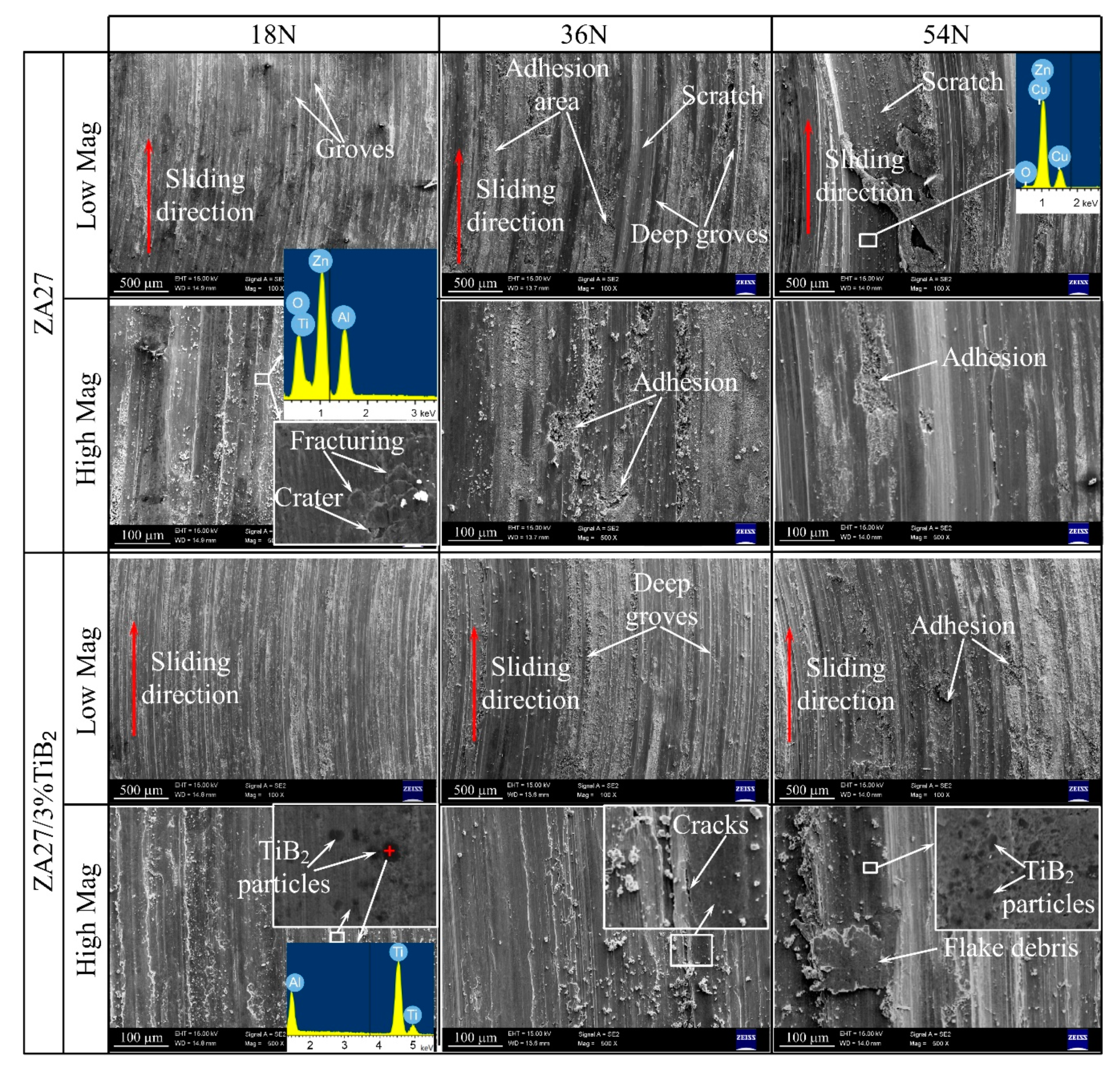
3.7. Worn Surface of the Samples

Figure 12 shows the worn surface and EDS analysis of the matrix and ZA27/3% TiB2 composite. The low magnification (low Mag) images show that all the worn surfaces are relatively smooth under 18 N, and there are a large number of groves and small debris on the surface, and the grove edges protrude and deform plastically, indicating that the samples have experienced a certain degree of abrasive wear. The so-called abrasive wear refers to the phenomenon that the abrasive particles scratch the mating surface during the relative movement of the friction pair and cause the material to fall off. The abrasive particles are usually surface protrusion, abrasive debris, or foreign hard particles. The high magnification (high Mag) image shows that the uniform fine grinding scratches along the sliding direction in the flat groves, which is a typical feature of oxidation wear. Generally, oxidation wear involves two successive processes: Destruction and regeneration of oxide film. When the formation speed of oxide film is higher than that of destruction, the oxide film can play a role in reducing the wear. However, for the high sliding speed or heavy load, the formation speed of oxide film is lower than the damage rate, the oxide film will break and may cause the adhesive wear. The EDS analysis shows that the worn surface is rich in O, Zn, Al, and Fe under the 18 N load, and the percentage of the O atom is 49.8%, which indicates that the stable oxide film is formed on the surface. In addition, a large number of cracks are distributed in the surface of the seemingly smooth oxide film, and some cracks are connected with each other, causing the fracturing of the sample surface.
The above analysis shows that there are some micro-protrusions on the surface of the counterpart, which are pressed into the sample surface under the normal load. Most of the micro protrusions do not plow the surface of the sample, but squeeze the alloy to both sides during the sliding process, thus causing the plastic flow of the material and forming the flat grooves, and scratching the surface of the oxide film, forming the fine oxide wear debris. Some protrusions with sharp corners micro-cut the sample surface to form deep groves and stripe debris. The tensile stress caused by the micro-protrusion pressing and the shear stress during the scratching process lead to the longitudinal crack perpendicular to the surface and the transverse crack extending from the indentation bottom to the surface in the oxide film, respectively. The longitudinal crack causes the oxide film to crack and promotes the oxygen atoms to diffuse into the surface layer, forming the white oxide distributed along the crack in the local enlarged picture. When the transverse crack propagates to the surface or intersects with the longitudinal crack, the oxide film fragments fall off and form a crater. These fallen oxide layers can also act as abrasive particles, leading to the three-body abrasive wear.
According to the simplified model proposed by Rabinowicz [42], the abrasive wear rate satisfies the following formula [36]:
d V d L = k a W H m
where L is the relative sliding distance between the abrasive particles and the worn surface, V is the wear volume, k a is the abrasive wear constant, which is related to the hardness, the shape of abrasive particles, and the number of abrasive particles that play a micro-cutting role, W is the load and H m is the hardness of the material.
The above formula shows that the abrasive wear rate is directly proportional to the load and inversely proportional to the hardness of the material. Compared with the matrix, the composite has a higher hardness, which reduces the protrusion pressing depth and plastic deformation of the material [43], so the wear degree of the composites is much lower. In addition, since the hardness of the matrix is significantly lower than that of the TiB2 particles, the matrix around the particles will be grinded preferentially during the wear process. As a result, the particles contact the protrusions of the counterpart and act as load-bearing elements, reducing the direct contact between the sample surface and the counterpart, thus having a protective effect on the matrix and the oxide film [44,45]. This has been verified by a large number of TiB2 particles distributed on the worn surface of the sample under the 18 N load.
When the load increases to 36 N, the surface of the matrix alloy becomes rough, and the grove depth increases obviously. There are a lot of V-shaped groves caused by micro-cutting, which indicates that the abrasive wear is increased. The EDS analysis shows that the grove surface mainly contains Zn and Al, indicating that the oxide film on the surface of the sample has been destroyed. This is mainly due to the fact that the high load increases the indentation depth of the micro protrusion into the specimen surface. During relative sliding, the micro-cutting in the surface is intensified. In addition to a large number of groves, there are a large number of adhesion areas on the surface. It shows that with the increase of contact stress and temperature, the specimen surface and the protrusion of the counterpart have undergone softening and plastic deformation, resulting in the formation of adhesion junctions between them. In the subsequent sliding, the junctions will fracture under the shear force. Generally, the location of shear fracture determines the degree of the adhesive wear. The deeper the fracture location, the more serious the wear. These adhesion areas and the above-mentioned scattered adhesion debris on the counterpart surface (Figure 10) confirm that the strength of some adherent junctions has exceeded the shear strength of the matrix alloy at this time and the shear failure occurs in the surface of the sample and results in the formation of the above-mentioned flake debris (Figure 9b). The broken adhesion junctions that adhere to the counterpart and subsequently scratch the surface of the specimen during the sliding process, form deep and wide groves. Under the load of 36 N, the abrasive wear degree of the composite samples increases, which is mainly reflected in the increase of the grove depth and width. However, there is no obvious adhesion on the worn surface, proving again the better adhesion resistance of the composite as compared to the matrix.
The hemispherical wear debris model proposed by Arcard in 1953 is a basic model for describing the adhesive wear, according to the model, the volume wear rate satisfies the following formula [46]:
d V d L = W 3 σ y
where V is the wear volume, W is the load, and σ y is the yield strength of the material. The above formula shows that the adhesive wear rate is directly proportional to the load and inversely proportional to the yield strength of the material. Our previous study has shown that TiB2 could significantly enhance the strength of ZA27 [16], the adhesive wear thus can be reduced.
When the load is increased to 54 N, the area and strength of the adhesive junction between the matrix sample and the counterpart increase obviously, and the shear failure occurs at the deeper position of the sample surface, resulting in a large area of surface material transfer and forms a coarse adhesion debris on the counterpart surface. Owing to the fact that the same material has the same plastic deformation and cold work hardening tendency, it is more likely to form new adhesive junctions, which further aggravates the degree of adhesive wear damage. Furthermore, a partial adhesion debris will cause severe plastic deformation on the surface of the sample under the contact stress, resulting in severe scratches of millimeters width. For the composite, a large number of deep groves appear on the worn surface, indicating that the sample has experienced serious abrasive wear. In addition, the adhesive zones also appear on the worn surface, indicating that due to the further increased load and temperature, the surface of the composite sample has undergone plastic deformation and the oxide film has been damaged, leading to the formation of the adhesive junction between the composite and the counterpart. The high magnification shows that the partial surface of the specimen is exfoliated under the action of friction force, forming flake debris, which indicates that the strength of the adhesive junction has exceeded the shear strength of the composite at this time, and the shear failure occurs in the surface layer of the specimen. However, most of the TiB2 particles still remain intact and well bonded to the matrix, which is shown in the local magnification image, indicating that the TiB2 particle can still play an anti-wear role due to the good interfacial bonding between the particle and the matrix.

4. Conclusions

In this work, ZA27/TiB2 in situ composites were prepared by diluting the in situ Al/TiB2 composite, which was used as the master alloy. The structure and wear-resistant properties of the composite were analyzed. The main conclusions are as follows:
(1) TiB2 particles were distributed uniformly in the matrix, and had an obvious refinement effect on the α-Al grain size. The hardness of the fabricated composites was significantly higher than that of the matrix and increases gradually with the increasing particle content.
(2) The friction coefficient of composites was lower than that of the matrix alloy except for the low load, and the temperature of the composite sample was significantly lower than that of the matrix alloy.
(3) The composite possessed an obvious wear resistance advantage as compared to the matrix, especially for the high load. The wear rate and specific wear rate of the composites were lower than that of the matrix alloy, for the load of 54 N, the wear rate of the matrix alloy was 3.9 times higher than that of the ZA27/3.0% TiB2 composite.
(4) The composites had better adhesive wear resistance properties compared with the matrix alloys, which have shown an obvious adhesive wear as the load increased to 36 N, while the ZA27/3.0% TiB2 composite did not show adhesive wear until the load increased to 54 N.

Author Contributions

Conceptualization, investigation, methodology, and writing—original draft, F.C.; validation and formal analysis, B.W.; resources, project administration, and supervision, Z.C. All authors have read and agreed to the published version of the manuscript.

Funding

This work was supported by the Natural Science Foundation of Jiangsu Province, China (BK20170543), the National Natural Science Foundation of China (Nos. 51801074, 51771041, 51574058, 51701085, 51525401), and the China Postdoctoral Science Foundation (2020M671406). This research received no external funding.

Acknowledgments

The authors wish to extend their sincere gratitude to the staff working at the Material Testing Center of Dalian University of Technology and Material Testing Center of Jiangsu University.

Conflicts of Interest

The authors declare that they have no known competing financial interests or personal relationships that could have appeared to influence the work reported in this paper.

Data Availability

The data that support the findings of this study are available from the corresponding author upon request.

References

  1. Liu, Y.; Li, H.; Jiang, H.-F.; Lu, X.-C. Effects of heat treatment on microstructure and mechanical properties of ZA27 alloy. Trans. Nonferr. Met. Soc. China 2013, 23, 642–649. [Google Scholar] [CrossRef]
  2. Ranganath, G.; Sharma, S.; Krishna, M. Dry sliding wear of garnet reinforced zinc/aluminium metal matrix composites. Wear 2001, 251, 1408–1413. [Google Scholar] [CrossRef]
  3. Jianhua, W.; Jianfeng, H.; Xuping, S.; Changjun, W. Effect of reverse modification of Al–5Ti–B master alloy on hypoeutectic ZnAl4Y alloy. Mater. Des. 2012, 38, 133–138. [Google Scholar] [CrossRef]
  4. Türk, A.; Kurnaz, C.; Şevik, H. Comparison of the wear properties of modified ZA-8 alloys and conventional bearing bronze. Mater. Des. 2007, 28, 1889–1897. [Google Scholar] [CrossRef]
  5. Savaşkan, T.; Azaklı, Z. An investigation of lubricated friction and wear properties of Zn–40Al–2Cu–2Si alloy in comparison with SAE 65 bearing bronze. Wear 2008, 264, 920–928. [Google Scholar] [CrossRef]
  6. Modi, O.; Rathod, S.; Prasad, B.K.; Jha, A.; Dixit, G. The influence of alumina particle dispersion and test parameters on dry sliding wear behaviour of zinc-based alloy. Tribol. Int. 2007, 40, 1137–1146. [Google Scholar] [CrossRef]
  7. Prasad, B.; Patwardhan, A.; Yegneswaran, A. Dry sliding wear characteristics of some zinc-aluminium alloys: A comparative study with a conventional bearing bronze at a slow speed. Wear 1996, 199, 142–151. [Google Scholar] [CrossRef]
  8. Mishra, S.K.; Biswas, S.; Satapathy, A. A study on processing, characterization and erosion wear behavior of silicon carbide particle filled ZA-27 metal matrix composites. Mater. Des. 2014, 55, 958–965. [Google Scholar] [CrossRef]
  9. Babic, M.; Mitrović, S.; Zivic, F. Effects of Al2O3 particle reinforcement on the lubricated sliding wear behavior of ZA-27 alloy composites. J. Mater. Sci. 2011, 46, 6964–6974. [Google Scholar] [CrossRef]
  10. Pretreatment process of SiC particles and fabrication technology of SiC particulate reinforced Zn–Al alloy matrix composite. Mater. Sci. Technol. 2001, 17, 954–960. [CrossRef]
  11. BobiĆ, B.; Bajat, J.; BobiĆ, I.; JegdiĆ, B. Corrosion influence on surface appearance and microstructure of compo cast ZA27/SiCp composites in sodium chloride solution. Trans. Nonferr. Met. Soc. China 2016, 26, 1512–1521. [Google Scholar] [CrossRef]
  12. Sharma, S.C.; Sastry, S.; Krishna, M. Effect of aging parameters on the micro structure and properties of ZA-27/aluminite metal matrix composites. J. Alloys Compd. 2002, 346, 292–301. [Google Scholar] [CrossRef]
  13. El-Khair, M.A.; Lotfy, A.; Daoud, A.; El-Sheikh, A. Microstructure, thermal behavior and mechanical properties of squeeze cast SiC, ZrO2 or C reinforced ZA27 composites. Mater. Sci. Eng. A 2011, 528, 2353–2362. [Google Scholar] [CrossRef]
  14. Seah, K.; Sharma, S.; Girish, B. Mechanical properties of as-cast and heat-treated ZA-27/graphite particulate composites. Compos. Part A Appl. Sci. Manuf. 1997, 28, 251–256. [Google Scholar] [CrossRef]
  15. Ranganath, G.; Sharma, S.C.; Krishna, M.; Muruli, M.S. A Study of Mechanical Properties and Fractography of ZA-27/Titanium-Dioxide Metal Matrix Composites. J. Mater. Eng. Perform. 2002, 11, 408–413. [Google Scholar] [CrossRef]
  16. Chen, F.; Wang, T.-m.; Chen, Z.-n.; Mao, F.; Han, Q.; Cao, Z.-Q. Microstructure, mechanical properties and wear behaviour of Zn–Al–Cu–TiB2 in situ composites. Trans. Nonferr. Met. Soc. China 2015, 25, 103–111. [Google Scholar] [CrossRef]
  17. Kai, X.; Huang, S.; Wu, L.; Tao, R.; Peng, Y.; Mao, Z.; Chen, F.; Li, G.; Chen, G.; Zhao, Y. High strength and high creep resistant ZrB2/Al nanocomposites fabricated by ultrasonic-chemical in-situ reaction. J. Mater. Sci. Technol. 2019, 35, 2107–2114. [Google Scholar] [CrossRef]
  18. Hong, T.; Li, X.; Wang, H.; Chen, D.; Wang, K. Effects of TiB2 particles on aging behavior of in-situ TiB2/Al–Cu–Mg composites. Mater. Sci. Eng. A 2015, 624, 110–117. [Google Scholar] [CrossRef]
  19. Rajan, H.M.; Ramabalan, S.; Dinaharan, I.; Vijay, S. Effect of TiB2 content and temperature on sliding wear behavior of AA7075/TiB2 in situ aluminum cast composites. Arch. Civ. Mech. Eng. 2014, 14, 72–79. [Google Scholar] [CrossRef]
  20. Chen, F.; Chen, Z.; Mao, F.; Wang, T.; Cao, Z. TiB 2 reinforced aluminum based in situ composites fabricated by stir casting. Mater. Sci. Eng. A 2015, 625, 357–368. [Google Scholar] [CrossRef]
  21. Kumar, S.; Sarma, V.S.; Murty, B.S. High temperature wear behavior of Al–4Cu–TiB2 in situ composites. Wear 2010, 268, 1266–1274. [Google Scholar] [CrossRef]
  22. Li, P.; Wu, Y.; Liu, X. Controlled synthesis of different morphologies of TiB2 microcrystals by aluminum melt reaction method. Mater. Res. Bull. 2013, 48, 2044–2048. [Google Scholar] [CrossRef]
  23. Ramesh, C.S.; Ahamed, A.K.M.A. Friction and wear behaviour of cast Al 6063 based in situ metal matrix composites. Wear 2011, 271, 1928–1939. [Google Scholar] [CrossRef]
  24. Wang, T.; Chen, Z.; Zheng, Y.; Zhao, Y.; Kang, H.; Gao, L. Development of TiB2 reinforced aluminum foundry alloy based in situ composites—Part II: Enhancing the practical aluminum foundry alloys using the improved Al–5wt%TiB2 master composite upon dilution. Mater. Sci. Eng. A 2014, 605, 22–32. [Google Scholar] [CrossRef]
  25. Sahoo, B.N.; Panigrahi, S.K. Development of wear maps of in-situ TiC+TiB2 reinforced AZ91 Mg matrix composite with varying microstructural conditions. Tribol. Int. 2019, 135, 463–477. [Google Scholar] [CrossRef]
  26. Zou, J.; Lu, D.-P.; Fu, Q.-F.; Liu, K.-M.; Jiang, J. Microstructure and properties of Cu–Fe deformation processed in-situ composite. Vacuum 2019, 167, 54–58. [Google Scholar] [CrossRef]
  27. Lee, J.; Lee, D.; Song, M.H.; Rhee, W.; Ryu, H.J.; Hong, S.H. In-situ synthesis of TiC/Fe alloy composites with high strength and hardness by reactive sintering. J. Mater. Sci. Technol. 2018, 34, 1397–1404. [Google Scholar] [CrossRef]
  28. Chen, F.; Mao, F.; Xuan, Z.; Yan, G.; Han, J.; Wang, T.; Cao, Z.; Fu, Y.; Xiao, T. Real time investigation of the grain refinement dynamics in zinc alloy by synchrotron microradiography. J. Alloys Compd. 2015, 630, 60–67. [Google Scholar] [CrossRef]
  29. Chen, T.J.; Yuan, C.R.; Fu, M.F.; Ma, Y.; Li, Y.D.; Hao, Y. In situ silicon particle reinforced ZA27 composites: Part 1—Microstructures and tensile properties. Mater. Sci. Technol. 2008, 24, 1321–1332. [Google Scholar] [CrossRef]
  30. Li, Z.Q.; Zhang, S.Y.; Wu, B.Y. Solidification and microstructure of ZA27/SiCp composite fabricated by mechanical-electromagnetic combination stirring process. Mater. Sci. Technol. 2001, 17, 465–471. [Google Scholar]
  31. Osório, W.R.; Freire, C.M.; Garcia, A. The effect of the dendritic microstructure on the corrosion resistance of Zn–Al alloys. J. Alloys Compd. 2005, 397, 179–191. [Google Scholar] [CrossRef]
  32. Prasad, B.; Modi, O.; Yegneswaran, A. Wear behaviour of zinc-based alloys as influenced by alloy composition, nature of the slurry and traversal distance. Wear 2008, 264, 990–1001. [Google Scholar] [CrossRef]
  33. Prasad, B.; Modi, O.; Khaira, H. High-stress abrasive wear behaviour of a zinc-based alloy and its composite compared with a cast iron under varying track radius and load conditions. Mater. Sci. Eng. A 2004, 381, 343–354. [Google Scholar] [CrossRef]
  34. Dinaharan, I.; Murugan, N. Dry sliding wear behavior of AA6061/ZrB2 in-situ composite. Trans. Nonferr. Met. Soc. China 2012, 22, 810–818. [Google Scholar] [CrossRef]
  35. Prasad, B. Sliding wear response of a zinc-based alloy and its composite and comparison with a gray cast iron: Influence of external lubrication and microstructural features. Mater. Sci. Eng. A 2005, 392, 427–439. [Google Scholar] [CrossRef]
  36. Savaskan, T.; Alemdağ, Y. Effects of pressure and sliding speed on the friction and wear properties of Al–40Zn–3Cu–2Si alloy: A comparative study with SAE 65 bronze. Mater. Sci. Eng. A 2008, 496, 517–523. [Google Scholar] [CrossRef]
  37. Mandal, A.; Chakraborty, M.; Murty, B. Effect of TiB2 particles on sliding wear behaviour of Al–4Cu alloy. Wear 2007, 262, 160–166. [Google Scholar] [CrossRef]
  38. Yadav, S.; Aggrawal, A.; Kumar, A.; Biswas, K. Effect of TiB2 addition on wear behavior of (AlCrFeMnV)90Bi10 high entropy alloy composite. Tribol. Int. 2019, 132, 62–74. [Google Scholar] [CrossRef]
  39. Kumar, N.; Gautam, G.; Gautam, G.; Mohan, A.; Mohan, S. Wear, friction and profilometer studies of insitu AA5052/ZrB2 composites. Tribol. Int. 2016, 97, 313–326. [Google Scholar] [CrossRef]
  40. Sharma, S.; Girish, B.; Somashekar, D.; Satish, B.; Kamath, R. Sliding wear behaviour of zircon particles reinforced ZA-27 alloy composite materials. Wear 1999, 224, 89–94. [Google Scholar] [CrossRef]
  41. Axe´n, N.; Jacobson, S. Transitions in the abrasive wear resistance of fibre- and particle-reinforced aluminium. Wear 1994, 178, 1–7. [Google Scholar] [CrossRef]
  42. Rabinowicz, E.; Mutis, A. Effect of abrasive particle size on wear. Wear 1965, 8, 381–390. [Google Scholar] [CrossRef]
  43. Gu, C.; Rong, W.; Guo, S.; Yang, Y. Dry sliding wear behavior of in situ Cu–TiB2 nanocomposites against medium carbon steel. Wear 2003, 255, 832–835. [Google Scholar] [CrossRef]
  44. Sivaprasad, K.; Babu, S.P.K.; Natarajan, S.; Narayanasamy, R.; Kumar, B.A.; Dinesh, G. Study on abrasive and erosive wear behaviour of Al 6063/TiB2 in situ composites. Mater. Sci. Eng. A 2008, 498, 495–500. [Google Scholar] [CrossRef]
  45. Zhang, Z.F.; Zhang, L.C.; Mai, Y.-W. Particle effects on friction and wear of aluminium matrix composites. J. Mater. Sci. 1995, 30, 5999–6004. [Google Scholar] [CrossRef]
  46. Archard, J.F. Contact and Rubbing of Flat Surfaces. J. Appl. Phys. 1953, 24, 981–988. [Google Scholar] [CrossRef]
Figure 1. Schematic diagram of the pin-on-disc wear test.
Metals 10 01663 g001
Figure 2. X-ray diffraction patterns of the fabricated ZA27/TiB2 composites.
Metals 10 01663 g002
Figure 3. Scanning electron micrographs of (a) ZA27, (b) ZA27/0.6% TiB2, (c) ZA27/1.8% TiB2, (d) ZA27/3% TiB2, (e) low-magnification, and (f) high-magnification transmission electron microscope images of ZA27/3% TiB2.
Metals 10 01663 g003
Figure 4. Hardness of the ZA27/TiB2 composites.
Metals 10 01663 g004
Figure 5. The coefficient of friction (COF) of the ZA27/TiB2 composites: (a) 18 N, (b) 36 N, (c) 54 N, (d) average COF.
Metals 10 01663 g005
Figure 6. Variation of the surface temperature as a function of the test duration for wear samples.
Metals 10 01663 g006
Figure 7. Wear rate of the ZA27/TiB2 composites: (a) Wear rate, (b) specific wear rate.
Metals 10 01663 g007
Figure 8. Macrophoto of the debris generated by the matrix alloy and composite.
Metals 10 01663 g008
Figure 9. SEM micrographs and energy dispersive spectrometer (EDS) analysis of the wear debris generated at three loads of 18, 36, and 54 N: (ac) ZA27 alloy, (df) ZA27/3% TiB2 composite.
Metals 10 01663 g009
Figure 10. Macrographs of the counterpart surfaces.
Metals 10 01663 g010
Figure 11. SEM micrographs of the counterpart: (a) ZA27/3.0% TiB2 (18 N), (b) ZA27 (54 N).
Metals 10 01663 g011
Figure 12. Worn surfaces of the ZA27 alloy and ZA27/3% TiB2 composite at different loads.
Metals 10 01663 g012
Table 1. Chemical composition (mass fraction) of ZA27 alloy (ASTM B 240-2004).
ElementAlCuMgZn
%25.5–28.02.0–2.50.012–0.020Balance
Publisher’s Note: MDPI stays neutral with regard to jurisdictional claims in published maps and institutional affiliations.

