Article

Bubble Formation by Short Plunging Jet in a Continuous Casting Tundish

1
Key Laboratory for Ecological Metallurgy of Multimetallic Ores (Ministry of Education), Northeastern University, Shenyang 110819, China
2
School of Metallurgy, Northeastern University, Shenyang 110819, China
*
Authors to whom correspondence should be addressed.
Metals 2020, 10(12), 1590; https://doi.org/10.3390/met10121590
Submission received: 8 November 2020 / Revised: 19 November 2020 / Accepted: 26 November 2020 / Published: 27 November 2020
(This article belongs to the Special Issue Mold and Tundish Metallurgy)

Abstract

:
A short plunging jet technique was developed to produce small bubbles in continuous casting tundish, with argon sealing, in order to promote the removal of inclusions smaller than 50 μm. The liquid steel coming out of the ladle shroud is accelerated and vibrated by gravity, leading to gas entrainment. This novel approach is free from bubbles growing along the nozzle surface due to the poor wetting condition, which is applicable to producing small bubbles in liquid steel. Water modeling was carried out to investigate the impact of the free-fall length on gas entrainment by a short plunging jet. The results show that gas can be entrained into the liquid bath with a free fall longer than 15 mm. Part of the entrained gas is separated from the gas sheath by the rough surface of the inflow stream, forming initial bubbles. These initial bubbles are further refined into small ones of 0.4~2.5 mm due to the turbulent flow in the pouring region. The cylindrical shield can effectively isolate the surface fluctuation caused by the short plunging jet; thereby, a stable slag layer in the tundish can be maintained during gas entrainment.

1. Introduction

Inert gas bubbling [1,2,3,4] has been regarded as an effective method for deep cleaning liquid steel in continuous casting. Inclusions smaller than 50 μm can be attached to bubble surfaces [5,6] or captured by bubble wakes [7,8], thereby moving upward with floating bubbles. Chang et al. [9] carried out full-scale water modeling to investigate the removal of inclusions in a four-strand tundish with gas bubbling. Online inclusion detection was achieved by recording the voltage pulse caused by nonconductive inclusion passing through the electric sensing zone. They reported that gas bubbling leads to a 12.84% decrease in the inclusion residual ratio. Moreover, the upward bubbly flow could homogenize the thermal field [10] and improve the flow characteristics [11,12] in the tundish. Cwudzinski [13] reported that gas bubbling located next to the stopper rod shows the best performance on flow control, with a 27% drop in dead volume. Chattopadhyay et al. [14] carried out water modeling to investigate slag behaviors in a four-strand tundish using gas injection from the ladle shroud. Their results indicated that an exposed eye would appear under the impact of floating bubbles on the slag–metal interface, resulting in slag entrainment, heat loss, and the reoxidization of liquid steel. Therefore, the drawback of gas bubbling cannot be neglected.
At present, bubble refinement in liquid steel has become a major concern in continuous casting in order to maintain a stable slag layer, meanwhile enhance the removal of inclusions. According to the review by Zhang et al. [15], the attachment probability of inclusions to bubbles is raised with a reduction in bubble size. In contrast with large bubbles, small bubbles have a lower terminal velocity that weakens their impact on the slag–metal interface. Moreover, the wide dispersion of small bubbles is also beneficial for inclusion removal by a bigger swapping area. Generally, inert gas is injected from refractory porous plugs located at the bottom of the tundish (called a gas curtain). However, bubbles expand along the nozzle surface [16] due to the poor interfacial wettability [17] of liquid steel to the refractory nozzle. Irons et al. [18] investigated gas bubbling in liquid pig iron. Bubble measurement was achieved by detecting the frequency of acoustic waves caused by bubble formation combined with the gas flow rate. Their results indicated that the bubbles’ size was larger than 15 mm even with an extremely low gas flow rate (0.03 L/min) and small nozzle (1.6 mm). Hence, reducing the nozzle size or decreasing the gas flow rate had little contribution to bubble refinement in liquid steel. Gas injection from ladle shroud was proposed to produce bubbles smaller than 1 mm. Bubbles can be forcibly separated from the nozzle by the shearing action of the high-velocity entry flow so as to inhibit bubble expansion due to nonwetting conditions. However, this approach was only effective with extremely small nozzle sizes and low gas flow rates, which are hard to realize in industrial operations. Li et al. [19] proposed that the vacuum treatment for liquid steel supersaturated with nitrogen could make small bubbles nucleate based on inclusions. Their results indicated that the separating bubbles, smaller than 10 mm, were uniformly distributed in the liquid bath so as to effectively promote the removal of inclusions. However, this method needs extra procedures for nitrogen dissolution and vacuum treatment, which will prolong the refining time and increase the heat loss of the liquid steel.
In the present study, small bubbles were produced by a novel ladle shroud located above the liquid surface in order to enhance the removal of inclusions smaller than 50 μm. The pipe flow was changed to a plunging jet after departing from the end of the ladle shroud. Due to the effect of gravity, the plunging jet became accelerated and began to shake, leading to gas entrainment at the interface between the liquid surface and the plunging jet. The size of the entrapped bubbles depends on the turbulence and terminal velocity of the plunging jet, which can be controlled by the length of the free fall. In this approach, bubble growth due to the nonwetting condition is prevented, and the approach is thus applicable to producing small bubbles in liquid steel.

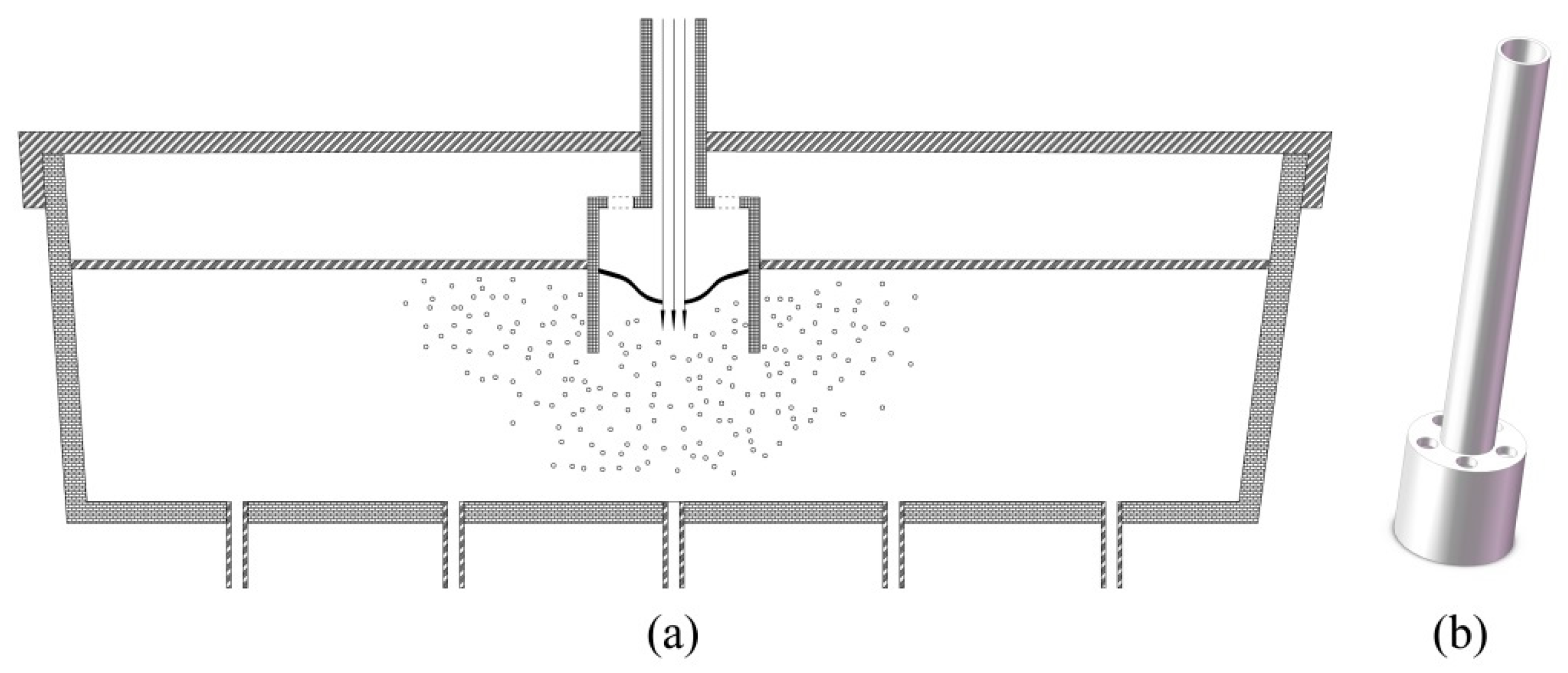
2. Physical Modeling

Physical experiments were carried out in a 1/(2.5)-scale model based on a prototype of a 12-t five-strand tundish, which produces 240 mm square billets at a casting speed of 1.55 m/min. The configuration and key dimensions of the model are shown in Figure 1. Liquid steel at 1823 k was replaced by water, owing to their comparable kinematic viscosities. The same modified Froude number (Fr) was maintained in the model and the prototype, as shown by Equation (1), in order to guarantee the dynamic similarity of the two systems.
F r m = v f m 2 g l m ρ lm ρ lm ρ gm = v f p 2 g l p ρ lp ρ lp ρ gp = F r p
where v is the velocity, m/s; g denotes the acceleration of gravity, m/s2; ρ represents density, kg/m3; l indicates the characteristic length, m; the subscripts m and p express the model and prototype, respectively. The entry flow rate was assigned as 45 L/min based on the production of the prototype, which is determined as follows:
Q fm = ( λ ) 5 2 ( ρ fp ρ fm ) 1 2 ( ρ lp ρ gp ρ lm ρ gm ) 1 2 Q fp
where Qfm and Qfp represent the entry flow rates of the model and prototype, respectively; m3/s, λ is the similarity ratio, -. The entire flow rate of the outlet remained equal to that of the entry flow so as to keep a stable liquid depth of 365 mm. The detailed experimental parameters were listed in Table 1.
As shown in Figure 2, the space under the tundish cover is completely filled with inert gas, which was originally proposed to avoid the reoxidation of liquid steel. In the present study, the inert gas could also be used for gas entrainment by a short plunging jet in order to produce small bubbles in the tundish bath. The pouring region is covered by a cylindrical shield, being connected to the end of the ladle shroud. The surface fluctuation caused by the plunging jet can thus be isolated so as to maintain a stable slag–metal interface outside the shield. Since plenty of bubbles would move out of the shield following the turbulent flow in the pouring region, negative pressure is formed in the upper space of the shield. As such, the inert gas can be sucked into the shield through the orifices in its top surface, achieving inert gas recycling without any fresh gas supply.
Bubbles were recorded by a high-speed camera (Photron Ltd., Tokyo, Japan) using a shutter speed of 1/2500 s, an aperture of 4.5 F, and light sensitivity of 250. A piece of LED light sheet was used to provide a sufficient background light source. Since bubbles were widely distributed in a three-dimensional space, the imaging distance would impact the bubble measurements. In the present study, a high sharpness prime lens was employed to record bubbles. In order to guarantee an accurate scale for bubble measurements, the prime lens focuses on a ruler so that only the bubbles on the plane of the ruler would be clearly recorded, while the other bubbles were kept blurred. Five focal planes were used to record enough bubbles located at different positions in each case. Bubble measurement was achieved using ImageJ postprocessing software. For each case, the average bubble size was obtained by batch processing of 30 photos, which were captured every 4 s. It should be noted that the shield was not involved in bubble recording in order to avoid any image distortion caused by the cylindrical perspex.

3. Results and Discussion

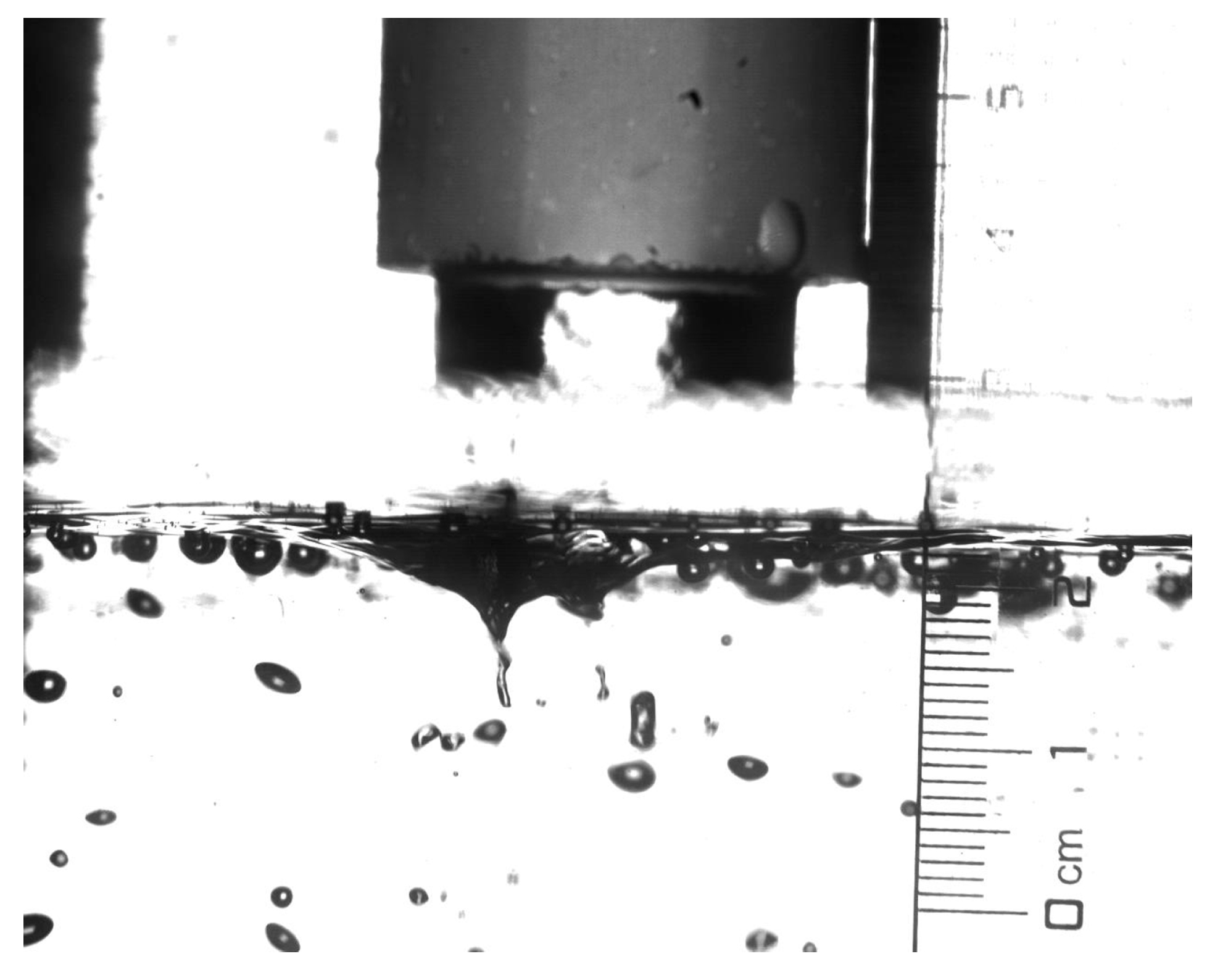
3.1. Formatting of Bubbles by Gas Entrainment

Figure 3 is a typical photo, displaying the bubble generation by the short plunging jet with a free fall length of 20 mm. The free surface is slightly depressed under the impact of the plunging jet, forming an air sheath around the jet. This air sheath on the free surface can be regarded as the nucleation of bubbles. After departing the ladle shroud, the flow stream changes from pipe flow to plunging flow due to the relaxation in the velocity profile [20]. Since the free fall length in the present study is far less than 3 times the ladle shroud’s diameter, the plunging jet is still stable and continuous. Therefore, the gas trapped in the flow stream can be neglected. Only film-wise entrainment is involved in bubble generation. After departing the gas sheath, the original bubbles were further refined by turbulence. The bubble break-up in turbulent flow can be predicted by the critical Weber number (Wec).
W e c = ρ w C 1 ε 2 / 3 d b 5 / 3 σ = 1.2
where ρw is the density of water, kg/m3; σ expresses the interfacial tension, N/m; ε represents the turbulence dissipation rate, m2/s3; C1 denotes the empirical constant, which is equal to 2. However, the high turbulence dissipation rate exists only in the region around the impacting point, formed by the mixing of the plunging jet and the liquid bath. Due to the limited residence time in the region with the high turbulence dissipation rate, the original bubbles can be partially broken rather than being refined into bubbles of critical size. Therefore, the size of the bubbles is still dominated by the process of bubble separation from the gas sheath. According to the scale in Figure 3, most of the bubbles were less than 2 mm in diameter.
It is noteworthy that some bubbles stay beneath the liquid surface rather than escaping directly. As a rising bubble approaches the air–water interface, it squeezes out the liquid of the film between the bubble and the liquid surface. The free energy of the system increases with the deformation of the bubbles, which, in turn, increases the kinetic energy from the relative motion. However, the impact of such small bubbles is limited due to their low terminal floating velocities, which is not enough for the liquid film to reach the critical thickness of rupture. Therefore, the bubble will bounce several times and then temporarily stay beneath the liquid surface to continue squeezing the liquid. The film can be ruptured by van der Waals force after its thickness reaches the order of 10−8 m [21], when the van der Waals force dominates the coalescence between the bubble and air, leading to the bubble escape from the liquid surface.
Due to the high flow velocity in the ladle shroud, the plunging jet can be classified as a turbulent flow, with a Reynolds number of 37,500. However, the surface of the plunging jet is still smooth at the exit of the ladle shroud. The gas entrainment even disappears when the exit of the ladle shroud is close enough to the liquid surface. Hence, the turbulence intensity of the plunging flow has no direct correlation with gas entrainment, which goes against the typical gas entrainment scenarios [22]. After departing from the ladle shroud, the flow stream is accelerated by gravity, while the volume flow rate still remains a constant, being equal to the inflow rate. With a low initial velocity, the plunging flow tapers due to surface tension in order to balance the volume flow rate. By contrast, the plunging flow vibrates and even disperses if its initial velocity is high enough. The mode of gas entrainment in the present study is shown in Figure 4. The plunging flow pulls gas into the liquid pool, forming a gas sheath around the impacting point. The quavering plunging jet shakes the tail of the gas sheath, resulting in part of the gas being separated from the gas sheath, forming a bubble in the liquid pool. The depth of the gas sheath depends on the vertical velocity of the plunging flow. When the gas sheath is longer, its tail becomes pointier and easier to separate.

3.2. Size of Entrapped Bubbles

In the present study, an entry flow rate of 45 L/min was employed, corresponding to an initial flow velocity of 1.5 m/s at the port of the ladle shroud. Figure 5 shows the bubbles generated by the short plunging jet with different free-fall lengths. The plunging jet sticks to the liquid surface by surface tension, with a free fall shorter than 10 mm. Almost no gas is entrained into the liquid pool because the fluctuation of the jet surface is insufficient to separate the bubbles from the tail of the gas sheath.
Plenty of models [23,24,25,26] were established to describe interfacial behaviors by plunging jets using a velocity as the criterion of gas entrainment. After a free fall range from 0 to 30 mm, the change of velocity increase caused by the free falling was no higher than 0.19 m/s, considering the liquid was coming out of the ladle shroud at an initial velocity of 1.5 m/s. However, gas entrainment changed dramatically with such a slight increase in the plunging flow velocity. An entry flow rate of 55 L/min, with a free fall length of 10 mm, was also employed in water modeling, corresponding to a plunging flow velocity of 1.83 m/s. This is even higher than the plunging flow velocity with the 30 mm free fall length in the previous cases. As a result, there is still no gas entrained into the liquid pool. Besides the terminal velocity, the free fall length also plays a vital role in the critical condition of gas entrainment.
Bubble generation was observed when the distance between the ladle shroud port and the liquid surface reached 15 mm. A high-speed video shows that the plunging jet vibrates at high frequency and small amplitude, owing to its short free fall combined with a high initial velocity. Part of the gas was separated from the gas sheath under the short and frequent shocks. As shown in Figure 6, postprocessing indicates that the bubbles were of the average size of 1.12 mm, with a free fall length of 15 mm. When the free fall length of the plunging jet reached 20 mm, the mean size of bubbles was 1.34 mm (increased by 19.64%). With the rise of free fall length, the vibration amplitude of the plunging jet at the impact point is enlarged, and its frequency declines. This increases the size of bubbles departing the gas sheath. Therefore, the average size of bubbles further rises to 1.68 and 2.17 mm with the free fall lengths of 25 and 30 mm, respectively.

3.3. Flow Rate of Gas Entrainment

The flow rate of gas entrainment is another major concern in bubbling operations. As the mechanism of gas entrainment is very complex, most of the mathematical models were established based on dimensional analysis combined with the regression of experimental data. Even so, each model was only valid in certain conditions, such as limited ranges of nozzle diameter, jet velocity, and jet length. For a vertical plunging jet shorter than 30 mm, the flow rate of gas entrainment can be estimated as follows [27]:
Q a = 0.04 v j 1.66 L j 0.48 D 1.59
The results indicate that gas entrainment by a short plunging jet ranged from 1.08 to 3.01 L/min. It is notable that the critical condition of bubble entrainment was not considered in this model. However, the modeling prediction is still consistent with the experimental observations when the free-fall length is longer than 15 mm. During industrial operations, the ladle shroud is as large as 64 mm in diameter so that the actual gas flow rate can be further increased to up to 20 L/min. Therefore, gas entrainment by a short plunging jet can provide a sufficient number of bubbles for the removal of inclusions.
As listed in Table 2, the conventional gas injection from a porous plug cannot produce small bubbles in liquid steel due to the bubble extension along the nozzle surface under nonwetting conditions. With the gas injection from the ladle shroud, gas was forcibly separated from the nozzle wall by the high-velocity entry flow, forming bubbles smaller than 3 mm. However, the entire gas flow rate must be limited to a very low level in this method, as the formation of small bubbles depends highly on the small size of the orifices. Degassing liquid steel with supersaturated nitrogen seems an effective approach to produce sufficiently small bubbles in liquid steel. It is noteworthy that both nitrogen dissolving and vacuum degassing are essentially batch operations that cannot fit into the existing continuous-casting process. Moreover, the heat loss of liquid steel would be increased due to the extra processing time. Therefore, this method is only applicable to the production of special steel on a small scale. By contrast, gas entrainment by a short plunging jet can be well combined with the existing continuous-casting process and produce a large amount of small bubbles, showing great potential for the deep cleaning of liquid steel.

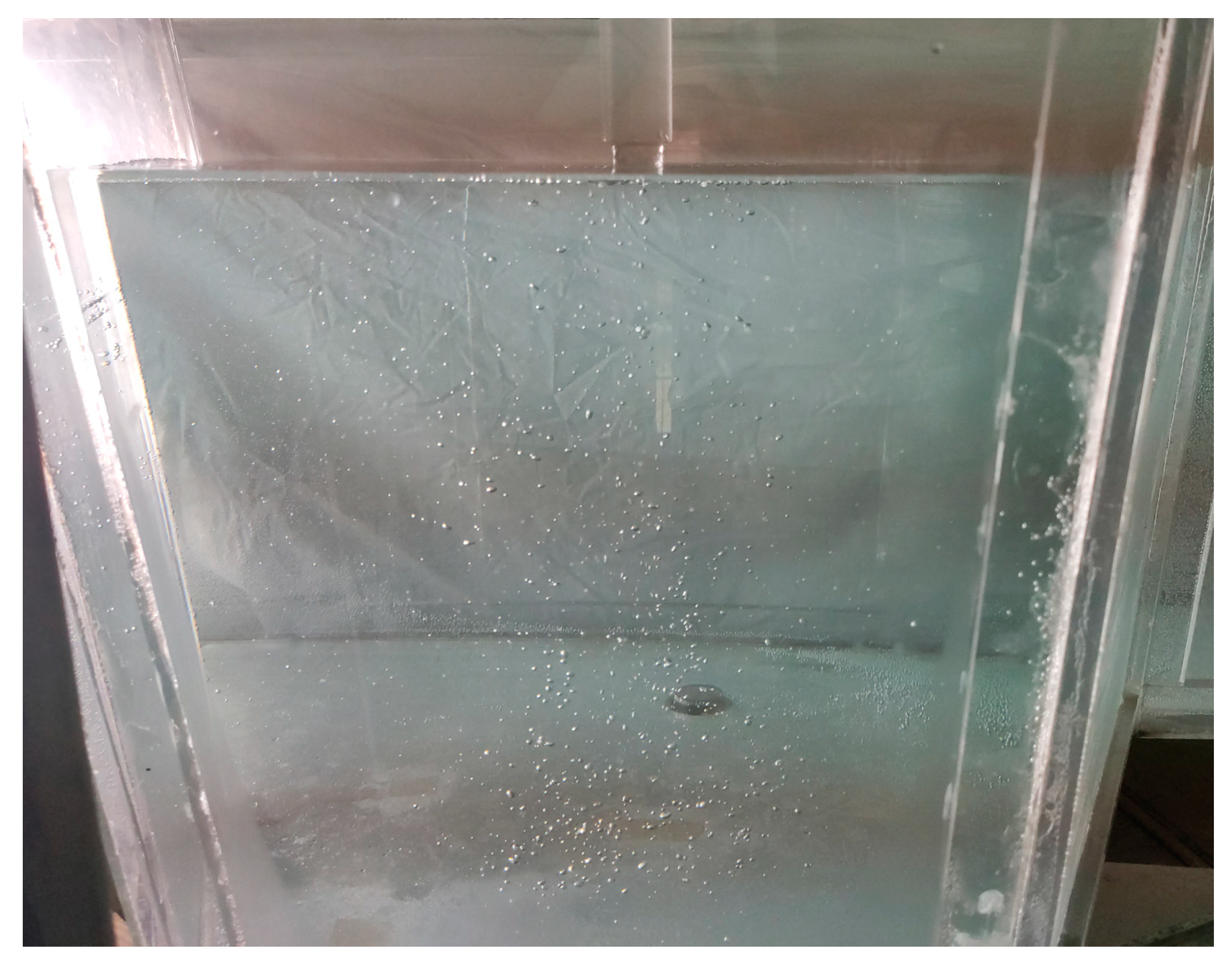
3.4. Distribution of Entrapped Bubbles

The distribution of bubbles also plays a vital role in the removal of inclusions. The Stokes number, as shown by Equation (5), is a dimensionless parameter corresponding to the following-up behavior of suspended particles to a liquid flow [30], which can be used to evaluate the horizontal movement of bubbles in the liquid pool.
S t k = ρ g d b 2 v 18 μ l 0
where ρg indicates the density of the gas, kg/m; v is the mean velocity of liquid flow, m/s; μ represents the dynamic viscosity of the liquid, Pa·s; l0 expresses the characteristic dimension of small vortices, m. According to the calculation of the Stokes number, the bubbles in all the cases closely follow the liquid flow, with a tracking error of less than 1%.
As shown in Figure 7, bubbles in such small sizes can disperse widely in the pouring region, owing to their low terminal floating-up velocities combined with the strong turbulence diffusion caused by the mixing of plunging jet and pool liquid. Compared with the bubbles produced by bottom gas blowing, the bubbles formed by a short plunging jet have an approximate double length of the path line in liquid pools. This provides a longer residence time for bubble dispersion, which could inhibit the coalescence of bubbles. Moreover, enlarging the distribution of bubbles can reduce repeated bubble sweeps in each element. The amount of inclusion removal by bubble swarms with different volumes can be calculated as follows:
N = V n t V n t P a P c V s V
V s = 6 Q π d b 2 4 π d b 3 H = 3 Q H 2 d b
where nt represents the number density of inclusions, number/m3; V is the volume of the bubble swarm, m3; Vs expresses the total sweep volume of bubbles, m3; Pa and Pc indicate the inclusion-bubble adhesion probability and collision probability, respectively. It is obvious that increasing the volume of the bubble swarm could effectively promote the global removal rate of inclusion, even with a given bubble amount and size distribution.

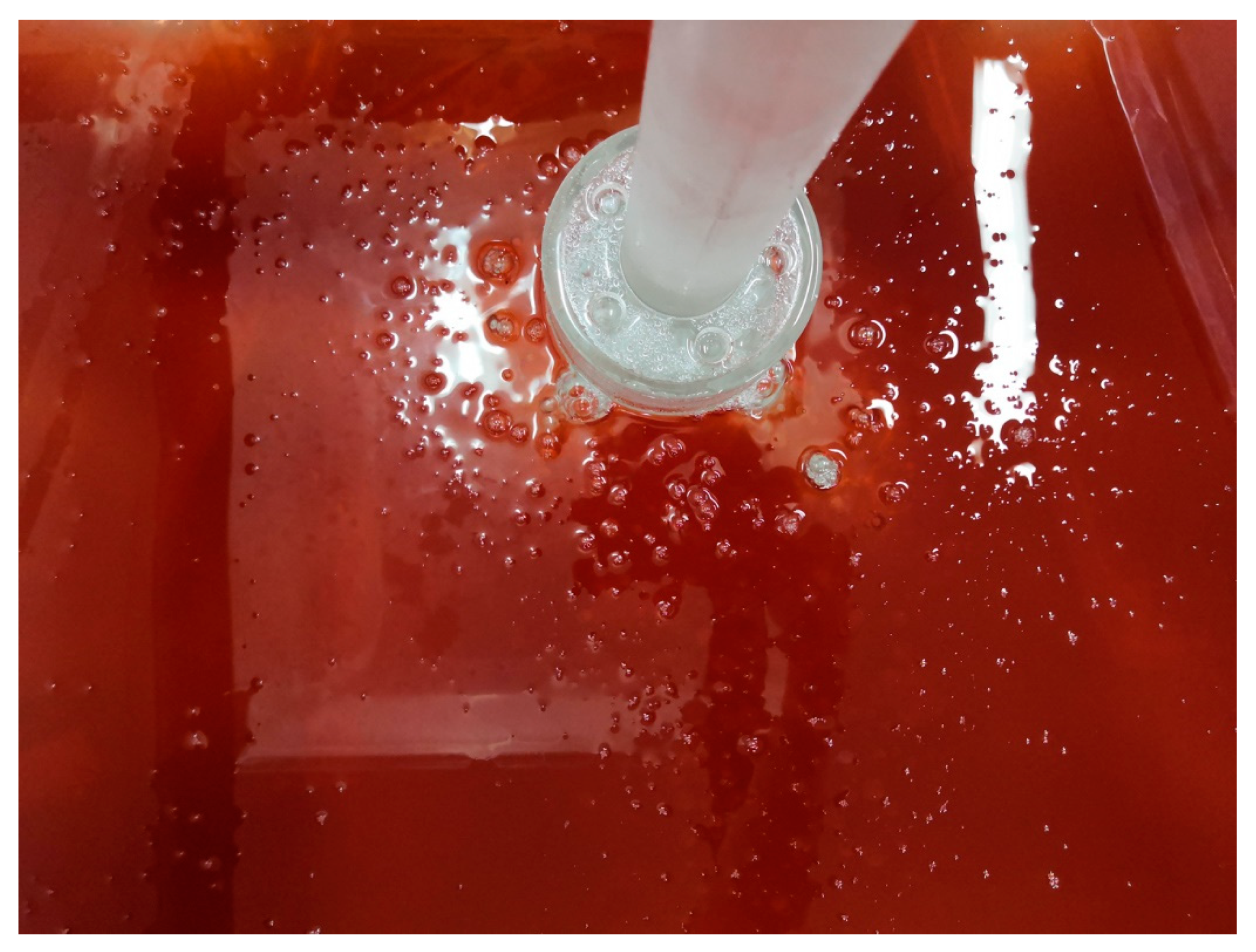
3.5. Slag Behavior under Gas Entrainment

The impact of floating bubbles on the slag–metal interface is regarded as the major drawback of gas bubbling operations, which may result in part of the liquid steel being exposed to air, leading to slag entrapment and the heat loss of the liquid steel. Compared with the conventional submerged jet, a short plunging jet would result in a more violent fluctuation in the slag layer due to its direct impact on the liquid surface. In order to maintain a stable slag layer during gas entrainment, the impact region is isolated by a cylindrical shield connected to the end of the ladle shroud. Therefore, the fluctuation caused by the plunging jet cannot conduct to the surface outside the shield. Moreover, the circulation of inert gas can be achieved through four orifices on the top of the shield without extra gas supply equipment, which ensures the stability of the bubbling system.
Figure 8 displays typical slag behavior under gas bubbling using a plunging jet with a 20 mm free fall. In the present study, the slag layer was set as 25 mm in thickness, corresponding to its thinnest status before the first ladle change. It is obvious that all the bubbles could pass through the slag layer smoothly. Owing to the isolation effect of the shield, the drastic fluctuation caused by the plunging jet was not propagated to the area outside the shield, and thereby the stability of the slag layer was maintained.

4. Conclusions

Gas entrainment by a short plunging jet was developed to produce small bubbles in continuous cast tundishes in order to promote the removal of inclusions. After departing from the port of the ladle shroud, the pipe flow was converted to a plunging jet with a rough surface. Owing to the vibration of the plunging jet, the entrained gas was separated from the gas sheath around the impact point, forming bubbles with diameters of 0.4~2.5 mm. With a jet velocity of 1.5 m/s, the gas began to be entrapped in the liquid bath when the free-fall length reached 15 mm. After that, the bubbles’ size and the entire gas flow rate increased when lengthening the free fall. The flow rate of the entrained gas ranged from 1.08 to 3.01 L/min, which can be dramatically increased to 20 L/min in the prototype. With a free fall length of 20 mm, the bubbles were distributed widely in the tundish bath, owing to the small bubble sizes combined with the strong turbulent flow. During gas entrainment, the surface fluctuation caused by the impact of the plunging jet can be well isolated by a shield so as to maintain a stable slag layer outside the pouring region. Inert gas can be recycled through orifices on the top surface of the shield, omitting extra gas-supply facilities. The entrainment by short plunging jet is free from bubble extension under nonwetting conditions and meets the requirement of small bubble size and large gas flow rate at the same time. Such an approach is thus applicable to deep cleaning liquid steel.

Author Contributions

Conceptualization, S.C. and Z.Z.; validation, L.S. and Z.L.; investigation, S.C.; data curation, B.L.; writing—original draft preparation, S.C.; writing—review and editing, Z.Z. All authors have read and agreed to the published version of the manuscript.

Funding

This work had financial support from the National Natural Science Foundation of China (51904061), the Fundamental Research Fund for the Central Universities (N182503029), and the China Postdoctoral Science Foundation (2018M641702).

Acknowledgments

The authors would also like to acknowledge the support from McGill Metal Processing Centre.

Conflicts of Interest

The authors declare no conflict of interest.

Nomenclature

Ddiameter of nozzle (m)
dbdiameter of bubble (m)
ggravity acceleration (m/s2)
Hdepth of liquid bath (m)
Ljlength of free fall (m)
lcharacteristic length (m)
ntnumber density of inclusions (number/m3)
Paadhesion probability of bubbles (-)
Pccollision probability of bubbles (-)
Qvolume flow rate (m3/s)
Vvolume of bubble swarm (m3)
Vsvolume of bubble sweep (m3)
vvelocity (m/s)
ρdensity (kg/m3)
εturbulence dissipation rate (m2/s3)
μdynamic viscosity (Pa·s)
σinterfacial tension (N/m)
FrFroude number (-)
StkStokes number (-)
Weccritical Weber number (-)

References

  1. Singh, P.K.; Mazumdar, D. A physical model study of two-phase gas–liquid flows in a ladle shroud. Metall. Mater. Trans. B 2018, 49, 1945–1962. [Google Scholar] [CrossRef]
  2. Cao, Q.; Nastac, L. Numerical modelling of the transport and removal of inclusions in an industrial gas-stirred ladle. Ironmak. Steelmak. 2018, 45, 984–991. [Google Scholar] [CrossRef]
  3. Chang, S.; Huang, W.X.; Zou, Z.S.; Li, B.K.; Guthrie, R.I.L. Motion behavior of micro-bubbles in a delta shape tundish using impact pad. Powder Technol. 2020, 367, 296–304. [Google Scholar] [CrossRef]
  4. Cwudzinski, A. Numerical and physical modeling of liquid steel flow structure for one strand tundish with modern system of argon injection. Steel. Res. Int. 2017, 88, 1600484. [Google Scholar] [CrossRef]
  5. Wierink, G.; Heiskanen, K. Modelling bubble-particle interaction with dynamic surface tension. Miner. Eng. 2010, 23, 973–978. [Google Scholar] [CrossRef]
  6. Wang, L.T.; Zhang, Q.Y.; Li, Z.B.; Xue, Z.L. Fundamental of inclusion removal from molten steel by rising bubble. J. Iron Steel Res. Int. 2004, 11, 5–9. [Google Scholar]
  7. Xu, Y.G.; Ersson, M.; Jonsson, P.G. A numerical study about the influence of a bubble wake flow on the removal of inclusions. ISIJ Int. 2016, 56, 1982–1988. [Google Scholar] [CrossRef] [Green Version]
  8. Duan, H.J.; Ren, Y.; Zhang, L.F. Inclusion capture probability prediction model for bubble floatation in turbulent steel flow. Metall. Mater. Trans. B 2019, 50, 16–21. [Google Scholar] [CrossRef]
  9. Chang, S.; Cao, X.K.; Hsin, C.H.; Zou, Z.S.; Isac, M.; Guthrie, R.I.L. Removal of inclusions using micro-bubble swarms in a four strand, full-scale, water model tundish. ISIJ Int. 2016, 56, 1188–1197. [Google Scholar] [CrossRef] [Green Version]
  10. Chang, S.; Zhong, L.C.; Zou, Z.S. Simulation of flow and heat fields in a seven-strand tundish with gas curtain for molten steel continuous-casting. ISIJ Int. 2015, 55, 837–844. [Google Scholar] [CrossRef] [Green Version]
  11. Chatterjee, S.; Asad, A.; Kratzsch, C.; Schwarze, R.; Chattopadhyay, K. Mixing and residence time distribution in an inert gas-shrouded tundish. Metall. Mater. Trans. B 2017, 48, 17–21. [Google Scholar] [CrossRef]
  12. Holzinger, G.; Thumfart, M. Flow interaction in continuous casting tundish due to bubble curtain operation. Steel. Res. Int. 2019, 90, 1800642. [Google Scholar] [CrossRef]
  13. Cwudzinski, A. Hydrodynamic effects created by argon stirring liquid steel in a one-strand tundish. Ironmak. Steelmak. 2018, 45, 528–536. [Google Scholar] [CrossRef]
  14. Chatterjee, S.; Li, D.H.; Chattopadhyay, K. Modeling of liquid steel/slag/argon gas multiphase flow during tundish open eye formation in a two-strand tundish. Metall. Mater. Trans. B 2018, 49, 756–766. [Google Scholar] [CrossRef]
  15. Zhang, L.F.; Taniguchi, S. Fundamentals of inclusion removal from liquid steel by bubble flotation. Int. Mater. Rev. 2000, 45, 59–82. [Google Scholar] [CrossRef]
  16. Chang, S.; Cao, X.K.; Zou, Z.S. Regimes of micro-bubble formation using gas injection into ladle shroud. Metall. Mater. Trans. B 2018, 49, 953–957. [Google Scholar] [CrossRef]
  17. Gerlach, D.; Biswas, G.; Durst, F.; Kolobaric, V. Quasi-static bubble formation on submerged orifices. Int. J. Heat Mass Transf. 2005, 48, 425–438. [Google Scholar] [CrossRef]
  18. Irons, G.A.; Guthrie, R.I.L. Bubble formation at nozzles in pig iron. Metall. Trans. B 1978, 9, 101–110. [Google Scholar] [CrossRef]
  19. Li, K.W.; Liu, J.H.; Zhang, J.; Shen, S.B. Theoretical analysis of bubble nucleation in molten steel supersaturated with nitrogen or hydrogen. Metall. Mater. Trans. B 2017, 48, 2136–2146. [Google Scholar] [CrossRef]
  20. Evans, G.M.; Jameson, G.J.; Rielly, C.D. Free jet expansion and gas entrainment characteristics of a plunging liquid jet. Exp. Therm. Fluid Sci. 1996, 12, 142–149. [Google Scholar] [CrossRef]
  21. Chesters, A.K.; Hofman, G. Bubble coalescence in pure liquids. Appl. Sci. Res. 1982, 38, 353–361. [Google Scholar] [CrossRef]
  22. Davoust, L.; Achard, J.L.; El Hammoumi, M. Air entrainment by a plunging jet: The dynamical roughness concept and its estimation by a light absorption technique. Int. J. Multiphase Flow. 2002, 28, 1541–1564. [Google Scholar] [CrossRef] [Green Version]
  23. Brattberg, T.; Chanson, H. Air entrapment and air bubble dispersion at two-dimensional plunging water jets. Chem. Eng. Sci. 1998, 53, 4113–4127. [Google Scholar] [CrossRef] [Green Version]
  24. Ma, J.; Oberai, A.A.; Drew, D.A.; Lahey, R.T., Jr.; Morage, F.J. A quantitative subgrid air entrainment model for bubbly flow-plunging jets. Comput. Fluids 2010, 39, 77–86. [Google Scholar] [CrossRef]
  25. Harby, K.; Chiva, S.; Munoz-cobo, J.L. An experimental study on bubble entrainment and flow characteristics of vertical plunging water jets. Exp. Therm. Fluid Sci. 2014, 57, 207–220. [Google Scholar] [CrossRef]
  26. Miwa, S.; Moribe, T.; Tsutsumi, K.; Hibiki, T. Experimental investigation of air entrainment by vertical plunging jet. Chem. Eng. Sci. 2018, 181, 251–263. [Google Scholar] [CrossRef]
  27. Yamagiwa, K.; Kusabiraki, D.; Ohkawa, A. Gas holdup and gas entainment rate in downflow bubble column with gas entrainment by a liquid jet operating at high liquid throughout. J. Chem. Eng. Jpn. 1990, 23, 343–348. [Google Scholar] [CrossRef] [Green Version]
  28. Chang, S.; Cao, X.K.; Zou, Z.S.; Isac, M.; Roderick, R.I.L. Microbubble swarms in a fill-scale water model tundish. Metall. Mater. Trans. B 2016, 47, 2732–2743. [Google Scholar] [CrossRef]
  29. Zhang, J.; Liu, J.H.; Yu, S.J.; Su, X.F.; Yan, B.J.; Yang, H. Bubble growth and floating behavior during degassing process of molten steel/(N2, H2) system. ISIJ Int. 2020, 60, 470–480. [Google Scholar] [CrossRef] [Green Version]
  30. Cao, Q.; Nastac, L. Mathematical investigation of fluid flow, mass transfer, and slag-steel interfacial behavior in gas-stirred ladles. Metall. Mater. Trans. B 2018, 49, 1388–1404. [Google Scholar] [CrossRef] [Green Version]
Figure 1. Top view of the model tundish with key dimensions (mm).
Metals 10 01590 g001
Figure 2. Setup of gas bubbling by short plunging jet: (a) working principles; (b) ladle shroud with shield.
Metals 10 01590 g002
Figure 3. Bubbles generated by gas entrainment of plunging jet with 20 mm free fall.
Metals 10 01590 g003
Figure 4. Mode of gas entrainment by short plunging jet.
Metals 10 01590 g004
Figure 5. Bubbles generated by plunging jet with free fall lengths of (a) 5 mm, (b) 10 mm, (c) 15 mm, (d) 20 mm, (e) 25 mm, (f) 30 mm.
Metals 10 01590 g005
Figure 6. Entrapped bubble size and gas flow rate under different free-fall lengths.
Metals 10 01590 g006
Figure 7. Distribution of bubbles generated by short plunging flow with a free fall length of 20 mm.
Metals 10 01590 g007
Figure 8. Slag behavior under gas bubbling using the novel ladle shroud.
Metals 10 01590 g008
Table 1. Operation parameters in prototype and model tundishes.
ParameterPrototypeModel
FluidMolten SteelWater
Temperature (K)1823298
Density (kg/m3)7038998
Viscosity (Pa·s)0.00640.0009
Flow rate (L/min)44645
Inner diameter of shroud (mm)6425
Depth of liquid bath (mm)912365
Table 2. Comparison of gas bubbling methods in liquid steel.
Bubbling MethodBubble SizeGas Flow RateSetup
Gas injection from porous plug [18]>15 mmUnlimitedPorous plug
Gas supply system
Gas injection from
ladle shroud [28]
0.2~4 mm0~3 L/minTiny orifices
Gas supply system
Degassing liquid steel with supersaturated nitrogen [29]0.2~10 mmNitrogen solubilityVacuum treatment
Nitrogen dissolving
Gas injection by short plunging jet0.4~2.5 mm0~20 L/minLadle shroud shield
Publisher’s Note: MDPI stays neutral with regard to jurisdictional claims in published maps and institutional affiliations.

