Article

Wearing Behavior of the α-Al9FeMnSi Intermetallic Compound Formed by Reactive Sintering onto AISI 304L Stainless Steel

by
Martín Salazar Ibarra
1,
Alfredo Flores Valdés
1,*,
José Concepción Escobedo Bocardo
1 and
Alfredo Alan Flores Saldívar
2,3,*
1
Metallurgical Engineering Department, Cinvestav Saltillo, Industria Metalúrgica 1062, Ramos Arizpe 25900, Mexico
2
Industry 4.0 Artificial Intelligence Laboratory, Dongguan University of Technology, Dongguan 523808, China
3
School of Mechanical Engineering, University of Electronic Science and Technology of China, Chengdu 611731, China
*
Authors to whom correspondence should be addressed.
Metals 2020, 10(12), 1567; https://doi.org/10.3390/met10121567
Submission received: 21 October 2020 / Revised: 13 November 2020 / Accepted: 16 November 2020 / Published: 24 November 2020

Abstract

:
In this study, using mixtures of pure Al, Si, Mn, and Fe powders, the α-Al9FeMnSi intermetallic compound was formed onto AISI 304L stainless steel samples by reactive sintering. The processing parameters were temperature (800, 850, and 900 °C) and applied pressure (15 and 20 MPa), using a constant holding time of 7200 s. In this paper, the influence of pressure and temperature on the microstructure, microhardness, and wear resistance of the formed layers was studied. Using X-ray diffraction (XRD), scanning electron microscopy (SEM), microhardness testing, and wearing measurements (pin on disc tests), the cross-section and top side of the coatings were observed and analyzed. We were able to determine the phase composition of cladded layers and interfaces as well as their morphology. The results indicated that several layers were formed during reactive sintering, i.e., an Al-diffusion layer on the top of the substrate, an interface, and the α-Al9FeMnSi coating itself. The microhardness values of the different layers formed were determined, ranging from 400 to 500 HV for the intermetallic coating, to 120 HV for the substrate. In this way, it was found that the formed intermetallic coating is suitable to increase the corrosion resistance of stainless steel. Additionally, all the coating showed high adherence to the substrate, exhibiting high microhardness and wear resistance. Pin on disc wearing tests showed the wearing mechanisms are predominantly delamination and ablation of the cladded layers and substrate.

1. Introduction

In terms of alloy usage and type, austenitic stainless steels represent the largest stainless steel family [1,2]. The use of stainless steel materials has continually increased thanks to their excellent corrosion resistance in various environments [3] and numerous industrial applications [4,5]. However, there is still a lack of performance at high wearing conditions, which may restrict its longevity and use. Therefore, aluminum intermetallic type coatings could be an acceptable substitute for enhancing the wearing tension of stainless steel components [6,7]. Additionally, the high thermal stability of these components can also be enhanced. Due to this, the idea of directly synthesizing AlSiFeMn-type intermetallic compounds using pure elements onto stainless steel substrates for coating reasons arose. This method was established on the evidence that elements including Cr, Fe, and Ni in the substrates, and the elements forming quaternary intermetallic mixtures of the Al-Si-Fe-Mn type can interdiffuse, constituting a region noted as the interdiffusion area [8]. Not only is the intermetallic layer formed, but also the perfect adherence conditions could be attained for such an area. The thermodynamics and kinetics of the growth and formation of a related quaternary intermetallic Al8FeMnSi2 have been studied by Flores et al. [9]. Their work determined that this phase is formed at high concentrations of Si, Fe, and Mn in aluminum, also giving the value of its standard Gibbs free energy of formation as:
8Al + 2Si + Fe + Mn = Al8FeMnSi2
ΔG0 = −186238 + 59.63T (J mol−1) (878–973 K).
The stoichiometry of the aforementioned period is marginally different from the one reported in this work, but the authors would state that due to the experience gained through time, specifically on the use of novel characterization techniques, the former phase is now well recognized as the α-Al9FeMnSi intermetallic phase.
On the other hand, different methods with various starting materials have been used for the synthesis of these advanced layers of reaction. During hot dip aluminizing (HDA) procedure, Al disseminates into the steel substrate, creating different intermetallic layers among the alloys and the steel substrate [10]. Current research has concentrated on improving the interfacial strength and controlling the growth and morphology of the intermetallic layers [11].
Reactive sintering, produced mainly for the amalgamation of ceramics, has recently been utilized as a production alternative option for composites [12,13] and various intermetallic compounds, such as aluminides and silicates [14,15]. In particular, the key benefits of this approach are related to avoid melting of most intermetallics in the case of high-melting temperatures, and to attain maximum pureness of the products when applying the protective atmosphere and pure powders. However, due to phenomena linked with the modification in the crystal lattice and unbalanced diffusivity of the materials, reactive sintering can contribute to porous products in some systems [16,17]. The interface behavior of composite materials has recently become the subject of research in the field of materials processing. Sabetghadam et al. [18] stated that both stainless steel (SS410)/Ni and Ni/Cu interfaces form an obvious transition zone. Solid solutions were observed over the diffusion area at the same time (Fe, Cr), (Fe, Ni), and (Fe, Cr, Ni).
On the other hand, some alloying elements have been mentioned, mainly Si, Mn, and Cr, with an hexagonal centered phase structure (h.c.p), instead of the β-Al5FeSi state, with a monoclinic structure, which could promote the production of the α state [19]. A number of α-type phases have been identified, which in stable ternary and quaternary systems exhibit many different compositions. Traces of transition elements such as copper, chromium, cobalt, or manganese have been suggested to facilitate the formation of the α phase [20].
The growth and formation of intermetallic compound layers during the contact of dissimilar metals at high temperatures is a common phenomenon. The morphology and growth of the formed layers are highly influenced by several factors. Diffusion coefficients increase by increasing temperature, and thus the growth rate rises [21].
Nowadays, steel wear resistance estimation is approached with some difficulties as the impact on the wear mechanisms of several variables are not well known. For example, it is not possible to formulate a significant correlation between wear resistance and hardness of materials [22]. Wear behavior depends on the attributes of the coating such as thickness, load bearing capacity, and hardness. Research about the sliding wear behavior of the 303 stainless steel included in [23,24], pointed out the existence of a substantial transfer of material during sliding to the alumina ball, close to that observed in the study of wearing and friction under dry conditions. It was noted that the uncoated substrate exhibited minimum resistance to alumina wear.
Toscano, et al. [25] have studied the Al9(MnFe)xSi intermetallic microstructure produced by reactive sintering from mixtures of pure Al, Si, Mn and Fe powders. These authors found that at temperatures above 700 °C, reactive sintering of powders occurred. Martínez-Perales et al. [26] reported the effect of processing parameters related to the creation of coatings of AlSiFexMny intermetallics by reactive sintering. Previous work carried out by authors on the formation of the Al9FeMnSi intermetallic compound included the use of the differential thermal analysis technique by placing thermocouples inside the pre-compacted tablets of the elemental powders Al, Si, Fe, and Mn [26]. In the mentioned work, it was shown that approximately at 580 °C, an endothermic event occurs associated with the formation of a liquid solution Al Si, and subsequently, as the temperature increases, exothermic events occur between 600 and 800 °C related to the formation of intermediate phases such as Al, Fe, Si o Al, Si, and Mn and even the quaternary Al9FeMnSi.
These studies showed that the temperature was the most significant variable that affected the formation of the coating, while pressure did not have an important effect. The outcomes showed that the best reactive sintering conditions were a temperature of 800 °C, 20 MPa strain, and 7200 s of reaction time. However, some aspects of microstructural evolution of these intermetallics as well as their wear behavior, have not been studied.
Therefore, the intention of this study was to explore the microstructural growth of the α-Al9FeMnSi intermetallic coating grown onto AISI 304L stainless steel substrates during reactive sintering. The effect of applied pressure and the temperature, at a constant sintering time, were determined, as well as the chemical composition, phase constituents, and microhardness of the different layers of response products. Finally, the wear performance of the coating layers was determined utilizing pin on discs measurements.

2. Experimental Procedure

The material utilized as substrate in this paper was the AISI 304L stainless steel (10 mm disks of diameter and 5 mm of thickness). The surface of each disk was mechanically activated by blasting with silica sand. No other processes were presented on these specimens before the preparation of the coatings.
High purity metallic powders (99.5 wt.% minimum) of Si, Mn, Fe, and Al were used. These powders were dry mixed during 600 s in an ultrasonic device (Buehler, Lake Bluff, IL, USA). Disks of 10 mm of width and thickness of 5 mm were obtained by pressing (560 MPa) 1 g of this mixture. The stoichiometric powder mixture ratio paired that of the α-Al9FeMnSi intermetallic phase.
In each experiment, a disk of powders was placed on a stainless steel disk and then this setup was sintered during 7200 s at 800, 850, or 900 °C and under applied pressure of 15 or 20 MPa. These operating parameters were selected from previous works [25,26]. In an infrared radiation device fitted with a quartz tube positioned coaxially with the loading axis of a universal Instron testing machine (Instron Mechanical Testing, Norwood, MA, USA), pressure and heat were simultaneously applied to the samples. Using two bars of TZM molybdenum alloy (Ti-Zr-Mo alloy), compression was carried out. In the experiments, Teflon sheets were used between the end of the bars and the powder sample to avoid a reaction between them. At the time of sintering, a steady flow of ultra-high purity Ar 99.999% min flowing at 0.2 L/s was used to avoid sample oxidation. The heating and cooling rates of the sintering cycles were kept constant at 0.8 °C/s.
Before microstructural analysis, the treated samples were chemically etched to reveal the microstructure using a solution of 0.5% HF for 2 s. The reaction products in the coating zone were structurally identified using the SEM. In addition, the coatings were analyzed using X-ray diffraction (XRD) (Phillips, Andover, MA, USA), with Cu-Kα radiation. Microhardness testing was carried out in a Vickers hardness tester (Wilson Buehler, Lake Bluff, IL, USA), a load of 0.05 kg was used. Microhardness profiles of the surface from the coating to the substrate of the samples were obtained.
Wear testing was performed utilizing a pin-on-disk wear tester (ASTM G99-04 Standard Practice). The pin sample was set, and the disk sample rotated at 400 rpm for 10 min, 50 N of applied load. The wear mass loss was calculated by weighting the sample before and after the test. The deteriorated surface of the pin and the wear remains collected during the tests, and were examined using SEM (Phillips, Andover, MA, USA) and energy dispersive spectroscopy (EDS) (Phillips, Andover, MA, USA).

3. Results and Discussion
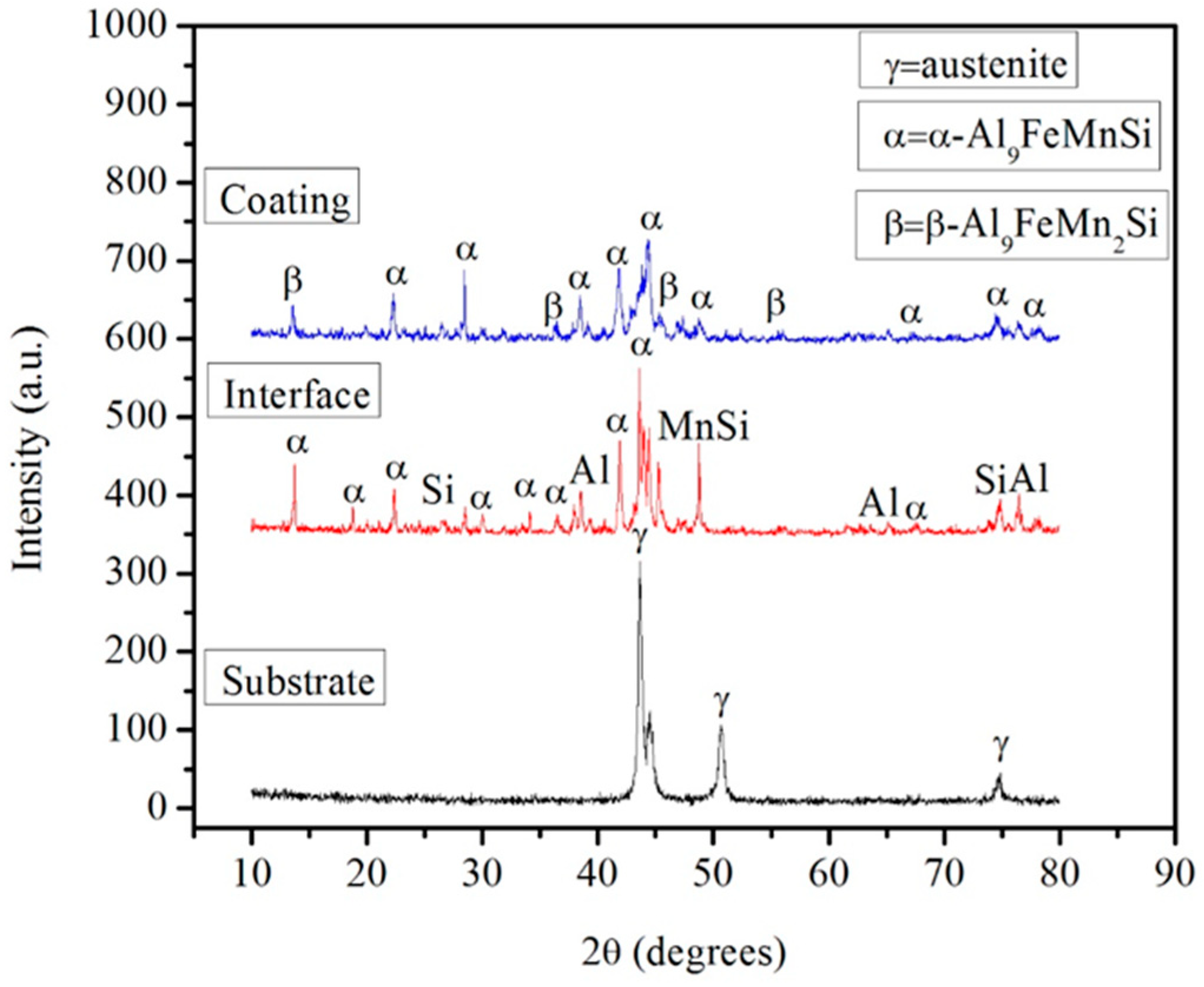
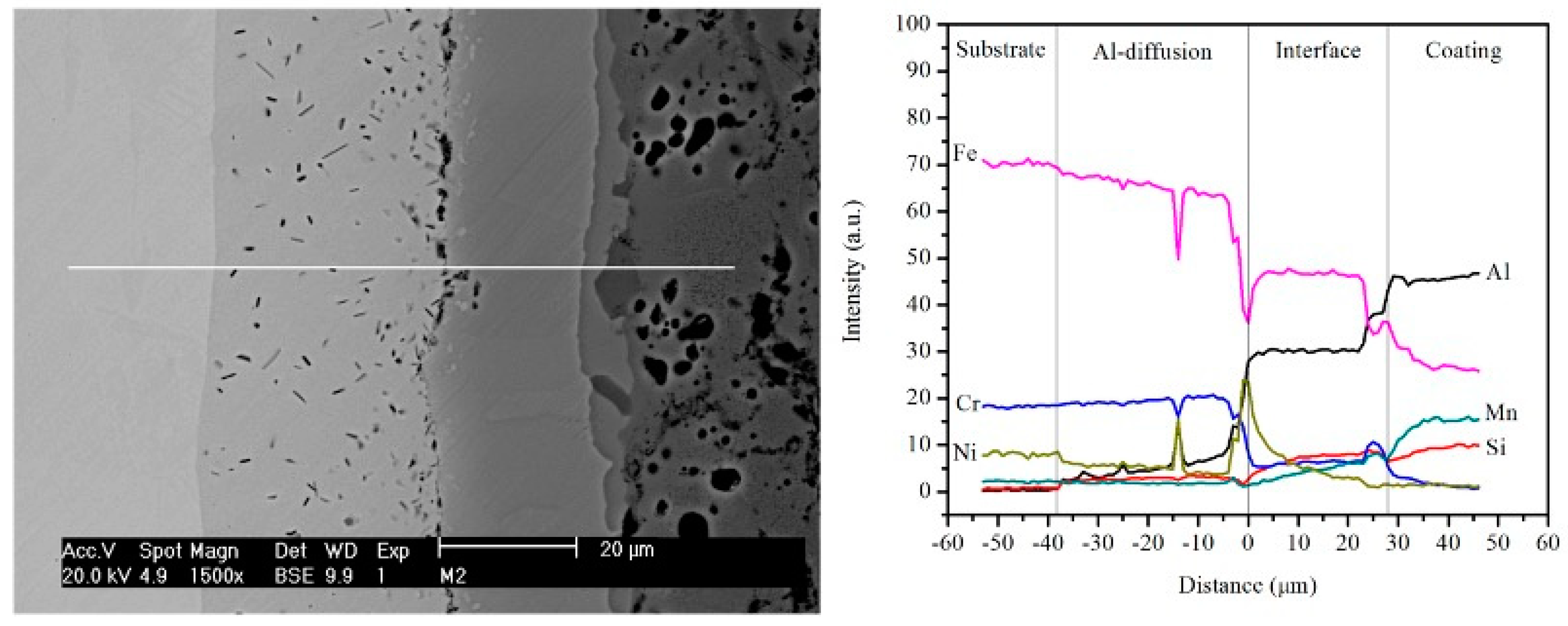
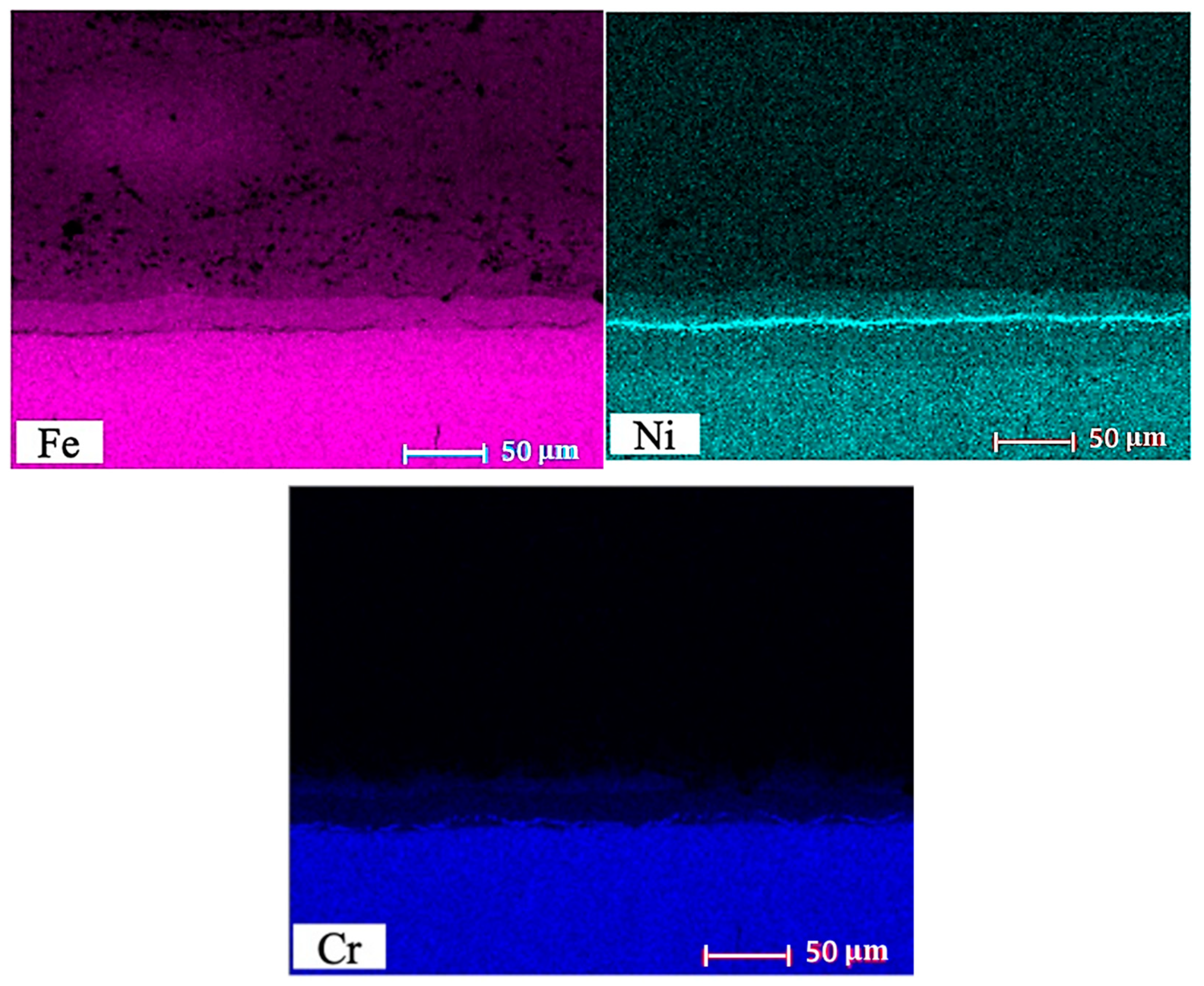
3.1. Microstructure

In Figure 1, SEM images of the Al, Si, Fe, and Mn powders before processing are presented. As observed, the morphologies of the powders are nodular for Al, acicular for Si, irregular for Fe, and angular for Mn.
During reactive sintering, the product (α-Al9FeMnSi intermetallic compound) is formed in an exothermic reaction among the Al, Fe, Mn, and Si powders in the compacted disk.
The green compact is sintered in the refining of powdered materials to increase density and decrease porosity. The increase in density is usually dependent on the form of the powder and the conditions imposed by the sintering, such as time and temperature. However, for a green compact created from mixed powders, the change in density is influenced not only by the conditions of sintering, but also by the nature of strengthening, particle volume fraction, and particle size [23].
Figure 2 presents a cross section of the coating developed after reactive sintering onto the AISI 304L stainless steel sample at a temperature of 850 °C, time of 7200 s, and 15 MPa of pressure. The microstructure presents four zones: the substrate, an Al-diffusion layer on the top of substrate, an interface, and the intermetallic coating. The intermetallic coating was fully developed and shows adequate adhesion to the substrate. However, some pores can be observed in the coating, most likely generated by the presence of a molten stage during processing of the coating. Porosity in the coating was affected by the conditions of the coating processing, powder characteristics, and imposed cooling circumstances [24].
The coating/substrate interface is continuous and thicker at higher processing temperatures, indicating that chemical interaction has taken place among the fragments of the pure elements and the substrate. This interface has no significant defects, resulting in excellent adhesion. The Al-diffusion layer appears and expands in the direction of the steel substrate by diffusion of Al. It is crucial to observe that the coatings sintered at 800, 850, and 900 °C have similar microstructures, with no appreciable porosity, as will be shown later.
In order to explain the observed microstructure and the mechanism of formation of the different reaction layers, it can be considered that a molten Al-Si phase is formed, which wets most of the particles still unreacted and spreads on the steel stainless AISI 304L surface. This molten Al-Si state responds with the Mn and Fe particles to form transitional intermetallic compounds in the powder mixture, which gradually form a coating on the base metal. Nevertheless, this molten state could also chemically decrease the oxide films on the surface of the substrate. Therefore, the layer thickness, which depends on the diffusion rate of chemical variety at the coating layer, is also dependent on the decrement rate of the oxide films. Nevertheless, the growth of the layer of the quaternary α-Al9FeMnSi intermetallic in the coating is still a function of pressure, processing time, and temperature.

3.2. Influence of Pressure and Temperature on the Coating Formation

Figure 3 presents the average thickness of the Al-diffusion layer and the interface including the scattering bars, as a function of processing temperature, at a fixed pressure of 15 MPa. It is clearly shown that the thickness of the interface and Al-diffusion layer increase (almost linearly) as processing temperature increases. Commonly, as the applied pressure and temperature increase, the thickness of the interface is incremented as well. This is a result of the diffusive nature of the coating creation method, which is positively favored by an increment in the applied pressure and temperature.
Figure 4 shows the XRD sequences of the AISI 404L substrate of the stainless steel, the interface, and the intermetallic coating, for a sample processed at 850 °C of temperature and a pressure of 20 MPa for 7200 s.
In the substrate XRD pattern, the peaks at 44°, 51°, and 75° are associated to the γ-Fe (austenite) phase of AISI 304L stainless steel [5]. Stainless steel alloying elements, such as Ni, Cr, Fe, and Mn, contribute significantly to the formation of this interface layer. The Al, Si, MnSi, and α-Al9FeMnSi phases were detected on the interface. The coating XRD pattern shows dominant peaks of the α-Al9FeMnSi and β-Al9FeMn2Si phases, which is consistent with results reported in literature [25,26]. The work carried out by Toscano presents a broad discussion of the origin of the indexation of the quaternary intermetallic phases of the AlSiFeMn type that precipitate the composition range studied in this work, which has allowed assigning the α-Al9FeMnSi stoichiometry as the dominant phase in this system in the composition range set.
Low intensity peaks of Al also appear due to the presence of this element in the coating. The XDR outcomes are in agreement with the analysis obtained from the EDS results. Such results were obtained from the coating cross-sections.
The chemical composition by the cross-section of the specimen was obtained by EDS microanalysis in the SEM by tracing elemental line scans. The line length was approximately 100 µm, including substrate, Al-diffusion layer, interface, and coating. An analysis was carried out to identify the distance of diffusion of the elements Mn, Fe, Al, Ni, Cr, and Si.
Figure 5 is a composition showing a SEM micrograph of a region of a sample processed at 850 °C and 20 MPa for 7200 s., where the corresponding EDS spectra of the different layers of reaction appear below the SEM micrograph of this figure. According to the EDS results, the substrate contains 71.50 wt.% Fe, 0.74 wt.% Si, 18.86 wt.% Cr, 7.01 wt.% Ni, and 1.89 wt.% Mn. The Al-diffusion layer (thickness of approximately 35 µm) contains not only Fe, Cr, and Ni, but also an important amount of aluminum which diffused from the powder mixture to the substrate. The interface (thickness of approximately 25 µm) analysis shows that the elements Fe and Al have a relevant concentration gradient with respect to the adjacent layers. Finally, as can be observed, the intermetallic coating is uniform, with high adherence to the substrate. The coating is mainly composed of 48.96 wt.% Al, 12.66 wt.% Si, 18.21 wt.% Mn, and 20.17 wt.% Fe, closely corresponding to the chemical structure of the α-Al9FeMnSi intermetallic phase, according to the measurements of Toscano [25] and Martínez [26].
Figure 6 shows the EDS line accumulation profiles of Fe, Al, Si, Mn, Cr, and Ni for the sample processed at 850 °C and 15 MPa for 7200 s. These concentration profiles agree with the composition and microstructure of the layers of reaction shown in Figure 5. In addition, it is possible to observe the existence of all elements at the interface and even diffusion of Si and Al into the substrate. The approximate thickness of the Al-diffusion layer is around 38 µm. Cr (at the limit between the interface and coating) and Ni (at the limit between the Al diffusion layer and interface) were also detected, which diffused approximately 35 and 15 µm, respectively. The average coating composition corresponds to that of the α-Al9FeMnSi intermetallic compound.
Figure 7 shows the EDS line accumulation profiles of Fe, Al, Si, Mn, Cr, and Ni for the sample processed at 20 MPa for 7200 s and 850 °C. The diffusion length of each element is presented. Under such conditions, no diffusion of elements to the substrate was observed. At the limit between the interface and the Al-diffusion zone, all elements are present. It can be observed that the coating holds not only Al, Fe, Mn and Si, but also short amounts of Ni and Cr near the interface region. The thickness of both the Al-diffusion layer and the interface decreased as the processing pressure was increased.
The EDS line concentration profiles are the result of the different diffusion rates of Al, Fe, Mn, Si, Cr, and Ni atoms during reactive sintering. It is considered that the diffusion rate during heating and holding at high temperature is related to the atomic radius of each element. It can be considered that both diffusion of Fe, Mn, Cr, and Ni from substrate to coating and diffusion of Fe, Mn, and Si from coating to substrate, contributed to the well metallurgical bonding of the coating. In the quaternary or ternary transitional intermetallic compound combination, Mn and Cr atoms can swap positions with Fe, occupying substitutional locations within the network, thus realizing the accumulation required of Fe so that the coating formation takes place. Including 4.40 wt.% of Cr to Al12(Fe,Cr)3Si2 minimized the value of its mesh parameter in the BCC arrangement, from 12.71 to 12.62 Å. Thereby, Cr atoms behave as a stabilizing agent permitting the development of this metastable state with a maximum compactness degree, improving its microhardness values [27]. Moreover, Fe and Cr elements correspond to the quaternary period and their atomic radius is similar. However, in comparison to Al atoms, there is a significant difference in electron density, atoms size, and electronegativity. In consequence, intermetallic compounds are easily created at the substrate/coating interface.
The aforementioned results presented and discussed above establish that the formation of the quaternary intermetallic coating by sintering reaction from primordial powders generate various profiles of phases on the AISI 304L substrate of the stainless steel. Certainly, this conduct is controlled by the characteristics of the physical-chemical of the base metal surface [28].
SEM-EDS elemental mapping has been used to find the distribution of the elements of a sample processed by reactive sintering at 850 °C and 20 MPa for 7200 s. Figure 8 shows the SEM and the corresponding EDS elemental mapping images of the cross-section of a sample processed at 850 °C and 20 MPa for 7200 s. As can be seen, Fe is present in all regions of the microstructure, Al is noticed in the Al-diffusion layer, the coating and the interface, and Si and Mn in the interface and coating. Finally, Cr and Ni are observed in the substrate and concentrated at the limit between the interface and coating and at the limit between the Al-diffusion layer and interface.

3.3. Microhardness Measurements

Figure 9a shows a SEM image of a cross-section of the processed sample at 850 °C and 15 MPa for 7200 s, and Figure 9b shows the microhardness measured at the different layers of the sample. The measurements were performed at the substrate, the Al-diffusion layer, the interface and the coating. As shown, microhardness values in the interfacial area and coating are greater than that of the substrate.
The absence of cracks around the indentations in the coating indicates a high toughness of this layer. This discovery contrasts with the implicit brittle behavior that represents most intermetallic compounds [17]. Microhardness decreases from 550 HV in the coating, to approximately 130 HV in the substrate, with intermediate values of 400 HV and 270 HV at the interface and the Al-diffusion layer, respectively. The measured microhardness of the substrate indicates that the temperature and pressure applied during reactive sintering did not affect this property of the substrate. Moreover, it is important to mention that cavity did not cause delamination of the coating, remaining tightly adhered to the substrate. The microhardness variation in the interface and coating zones can be attributed to the formation of ternary phases of β-Al9Fe2Si2 or α-AlFeSi type, which occurs in addition to the formation of the quaternary intermetallic compound α-Al9FeMnSi. However, other elements such as Ni and Cr, concentrated at the interface, forms rather complex structures not determined by X-ray diffraction.
Figure 10 presents the average microhardness values of the sample layers as a result of processing temperature at a constant processing strain of 20 MPa and time of 7200 s including the scattering bars, while Table 1 shows the complete set of measurements performed. As can observed, microhardness in all analyzed regions increased as processing temperature was increased.

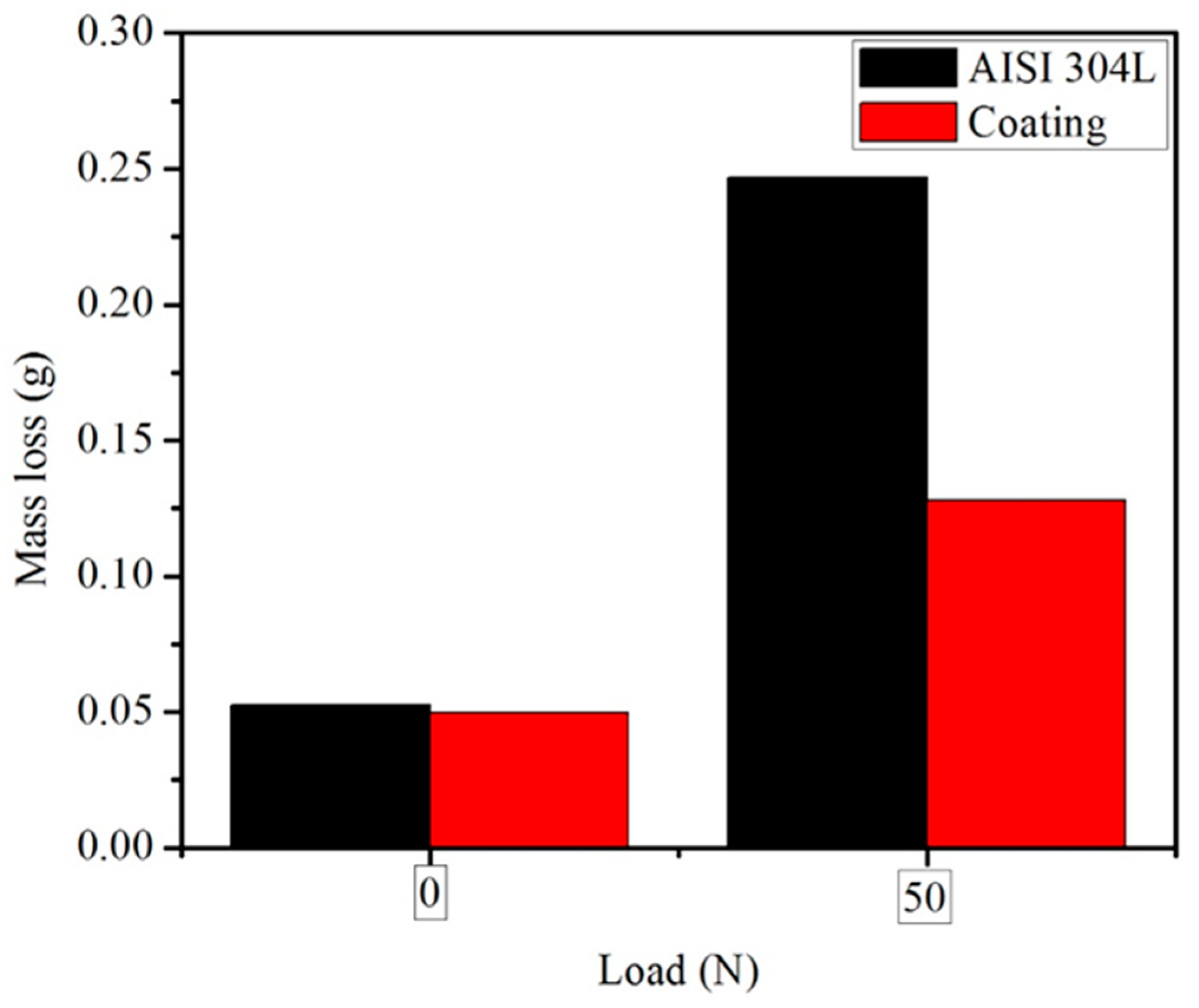
3.4. Wearing Mechanism

Figure 11 shows the mass loss of coated and uncoated (α-Al9FeMnSi coating) specimens of AISI 304L stainless steel as a function of load applied after pin-on-disk wear testing. For wear conditions without applying load, the loss of mass in the case of the AISI 304L stainless steel and of the coating is very similar. The wear resistance was analyzed based on the mass loss: the less the mass loss, the greater the resistance to wear. For wearing conditions with a load of 50 N, the mass loss for both materials increases. However, the mass loss of 304L stainless steel (0.25 g) is significantly greater than the α-Al9FeMnSi coating (0.12 g). Therefore, the coating has a significantly higher wear resistance than 304L stainless steel. Normally, compressive stress and shear stress are increased as the applied load increases.
Figure 12 shows the average mass loss values including the scattering bars of the coated stainless steel AISI 304L (α-Al9FeMnSi coating) as a function of processing pressure and temperature after pin-on-disk wear testing (constant load of 50 N). The samples coated at 800 °C showed a relatively higher mass loss (lower wear resistance) as compared with the samples coated at 850 and 900 °C. This behavior is attributed to the effect of temperature and pressure on the coating characteristics. The quaternary intermetallic coating has a microhardness of approximately 550 HV and the AISI 304L stainless steel substrate of 100 HV. When microhardness increases, the wear resistance also increases, causing lower mass loss. The coating has significantly higher wear resistance at the following processing parameters: temperatures of 850 and 900 °C and a pressure of 20 MPa.
Figure 13 shows SEM images of untreated and coated (α-Al9FeMnSi coating) specimens of AISI 304L stainless steel after pin-on-disk wear testing. The processing parameters were 900 °C and 20 MPa. It can be noted in both images that the wearing tracks run parallel with the sliding trajectory of the disk. The depth and area of wearing tracks of the intermetallic coating (Figure 13b) are considerably smaller than those of AISI 304L stainless steel (Figure 13a). However, a high amount of debris along the grooves was produced during the test, which illustrates that abrasive wearing happens during the wearing process of the coating, as observed in Figure 13b. The relative surface hardness of the substrate increases because of the presence of the intermetallic coating, thus significantly increasing the substrate’s wear resistance of the slide.
Figure 14 shows SEM images of untreated and coated (α-Al9FeMnSi coating) specimens of AISI 304L stainless steel after pin-on-disk wear testing. The processing parameters were 850 °C and 20 MPa. It should be noted that the coating attained at 850 °C exhibits better wearing behavior because only small peelings are observed at the tracks (Figure 14a). This absence of peelings indicates that only adhesive wearing was involved. The smeared surface appearance is common of adhesive wearing and the wear track profiles present evidence of extrusion and ploughing of the worn material in the external side the wearing tracks [7]. For the untreated AISI 304L stainless steel (Figure 14b), higher wearing was found, as the wearing surface presented evidence of abrasion and deformation on the wearing tracks.
The characteristics of the wearing products are consistent with plastic deformation [22]. Figure 15 shows EDS and the corresponding SEM image elemental mapping of the coating of a sample processed at 850 °C and 20 MPa for 7200 s after pin-on-disk wear testing. During sliding, the quaternary intermetallic is fragmented, generating particles that act as abrasive on the surface, leading to the appearance of two-body abrasive wearing. Areas with cracks can be observed, which results from the delamination process of layers formed by transfer and adhesion of wearing particles.
The adhesive areas or points would be cracked off with the sliding surfaces relative movement. Ruptures did not normally occur in the adhesive junction, but rather in the hardness lower material of the two parts where the transfer was located [29]. The transfer phenomenon was accepted by the distribution area of the worn surface elements of the quaternary intermetallic compound, as determined by EDS elemental mapping in SEM. According to this elemental mapping, Al, Si, Mn, Fe, and Cr were evenly dispersed in the intermetallic coating without enhancement phenomenon, which demonstrated that the coating even maintained both abrasion resistance and good integrity after the dry friction.
In this study, wearing took place due to physical interactions between the two shifting surfaces. Normally, compressive and shear stress increase as the load applied was increased, then these stresses were the primary causes for the transfer layers peeling-off. Figure 16 presents a corresponding EDS spectrum (taken at the zones indicated by numbers 1 through 3) and SEM image of the coating of a sample processed at 850 °C and 20 MPa for 7200 s after pin-on-disk wear testing.
The SEM analysis of worn surfaces on the quaternary intermetallic coating, confirmed the peeling-off of transfer layers (Figure 16). This figure also includes the semi-quantitative chemical analysis at the indicated points of the coating. Fissures were also observed at the surface and subsurface layers of the coating, as indicated by the arrows in the SEM image. Additionally, local microfracture of the quaternary intermetallic may happen due to the repetitive stresses of shear and compression.
Figure 17 shows a SEM image of an area of the coating of a sample processed at 850 °C and 20 MPa for 7200 s after pin-on-disk wear testing (load of 50 N) and EDS spectra of the indicated particles, including their semi-quantitative chemical analysis.
The debris of loose wear had the same color and aspect as the intermetallic coating, suggesting that during the wearing test, adhesive wearing occurred. There was high local pressure between plastic deformation, adhesion, contacting asperities, and the resultant formation of local junctions due to dry sliding, which contributed to high local pressure between contacting asperities [30].
Such results imply that intermetallic coating particles may behave as a lubricant, diminishing wearing. Therefore, the main mechanism of wearing was adhesive wearing. Delamination theory describes the crack initiation, shear plastic distortion, and their propagation through the contact surfaces, resulting in lamination debris. The aforementioned theory qualitatively predicts that thin flake-like sheets will form the shape of wear particles and that the surface layer can cause substantial plastic deformation [31].

4. Conclusions

In this study, coatings of the α-Al9FeMnSi intermetallic compound onto 304L stainless steel were successfully obtained using the reactive sintering processing technique. Temperatures between 800 and 900 °C and pressures between 15 and 20 MPa at a constant response time of 7200 s were used.
Microstructure formation mechanism at the interface layers can be primarily considered as metallurgical bonding diffusion, where the Cr and Fe atoms of the stainless steel react with the elements Fe, Mn, Si, and Al of the quaternary intermetallic α-Al9FeMnSi during its formation by reactive sintering, conducting to the development of a coating firmly adhered to the substrate.
The microhardness of the α-Al9FeMnSi constituting the coating is undoubtedly higher than that of the substrate. Its maximum microhardness was up to 550 HV against a maximum value of 130 HV for the substrate.
The coating obtained by reactive sintering, mainly composed by the quaternary α-Al9FeMnSi intermetallic, can unquestionably improve the wearing resistance of the stainless steel 304L.
It was found that the main wearing mechanism of the quaternary α-Al9FeMnSi intermetallic coating was adhesive wearing.

Author Contributions

Conceptualization, A.F.V., J.C.E.B., M.S.I. and A.A.F.S.; methodology, A.F.V., J.C.E.B., and M.S.I.; software, M.S.I.; validation, A.F.V., J.C.E.B., and M.S.I.; formal analysis, A.F.V., J.C.E.B., and M.S.I.; investigation, M.S.I.; resources, A.F.V., and J.C.E.B.; data curation, A.F.V., J.C.E.B., M.S.I., and A.A.F.S.; writing—original draft preparation, M.S.I.; writing—review and editing, A.F.V., J.C.E.B., and A.A.F.S.; visualization, A.F.V., and A.A.F.S.; supervision, A.F.V., and J.C.E.B.; project administration, A.F.V., and J.C.E.B.; funding acquisition, A.F.V., and J.C.E.B. All authors have read and agreed to the published version of the manuscript.

Funding

This research was funded by CONACYT, under the Coahuila State grant, number I0017-grant SEP-CONACYT CB-0257527. This work was supported by the Ministry of Science and Technology of China as part of a National Key Project (Grant No. 2018YFB1003203) and by the Dongguan University of Technology under the Industry 4.0 Smart Design and Innovation Platform grant (No. KCYXM2017012).

Acknowledgments

All the authors would like to thank CONACYT for the financial support. A. A. Flores Saldivar would like to thank the Ministry of Science and Technology of China and the Dongguan University of Technology for their financial support.

Conflicts of Interest

The authors declare no conflict of interest.

References

  1. Cui, Y.; Lundin, C.D.; Hariharan, V. Mechanical behavior of austenitic stainless steel weld metals with microfissures. J. Mater. Process. Technol. 2006, 171, 150–155. [Google Scholar] [CrossRef]
  2. Özyürek, D. An effect of weld current and weld atmosphere on the resistance spot weldability of 304L austenitic stainless steel. Mater. Des. 2008, 29, 597–603. [Google Scholar] [CrossRef]
  3. Jin, X.; Wang, B.; Xue, W.; Du, J.; Wu, X.; Wu, J. Characterization of wear-resistant coatings on 304 stainless steel fabricated by cathodic plasma electrolytic oxidation. Surf. Coat. Technol. 2013, 236, 22–28. [Google Scholar] [CrossRef]
  4. Leyland, A.; Lewis, D.; Stevensom, P.; Matthews, A. Low temperature plasma diffusion treatment of stainless steels for improved wear resistance. Surf. Coat. Technol. 1993, 62, 608–617. [Google Scholar] [CrossRef]
  5. Sayyedan, F.S.; Enayati, M. Evaluating oxidation behavior of amorphous aluminum phosphate coating. Appl. Surf. Sci. 2018, 455, 821–830. [Google Scholar] [CrossRef]
  6. Dorfman, M.R. Thermal Spray Coatings. In Handbook of Environmental Degradation of Materials; Elsevier: Amsterdam, The Netherlands, 2018; pp. 469–488. [Google Scholar]
  7. Silva, F.; Bedoya, J.; Dosta, S.; Cinca, N.; Cano, I.; Guilemany, J.; Benedetti, A. Corrosion characteristics of cold gas spray coatings of reinforced aluminum deposited onto carbon steel. Corros. Sci. 2017, 114, 57–71. [Google Scholar] [CrossRef] [Green Version]
  8. Flores-Valdés, A.; Castillejos-Escobar, A.; Acosta-González, F.; Escobedo-Bocardo, J.; Toscano-Giles, A. The Development of Surface Coatings for Co-Cr-Mo Alloys Based on Quaternary AlSiFeMn Intermetallic Compounds. In Cobalt-Base Alloys for Biomedical Applications; ASTM International: West Conshohocken, PA, USA, 2009; p. 179. [Google Scholar]
  9. Flores-V., A.; Sukiennik, M.; Castillejos-E., A.H.; Acosta-G., F.A.; Escobedo-B., J.C. A kinetic study on the nucleation and growth of the Al8FeMnSi2 intermetallic compound for aluminum scrap purification. Intermetallics 1998, 6, 217–227. [Google Scholar] [CrossRef]
  10. Cheng, W.-J.; Wang, C.-J. Effect of chromium on the formation of intermetallic phases in hot-dipped aluminide Cr–Mo steels. Appl. Surf. Sci. 2013, 277, 139–145. [Google Scholar] [CrossRef]
  11. Azimaee, H.-R.; Sarfaraz, M.; Mirjalili, M.; Aminian, K. Effect of silicon and manganese on the kinetics and morphology of the intermetallic layer growth during hot-dip aluminizing. Surf. Coat. Technol. 2019, 357, 483–496. [Google Scholar] [CrossRef]
  12. Chen, C.; Yang, J.; Chu, C.; Qiao, G.; Bao, C. Porous nano-Al2O3/Fe–Cr–Ni composites fabricated by pressureless reactive sintering. Mater. Chem. Phys. 2011, 128, 24–27. [Google Scholar] [CrossRef]
  13. Zou, B.; Shen, P.; Cao, X.; Jiang, Q. The mechanism of thermal explosion (TE) synthesis of TiC–TiB2 particulate locally reinforced steel matrix composites from an Al–Ti–B4C system via a TE-casting route. Mater. Chem. Phys. 2012, 132, 51–62. [Google Scholar] [CrossRef]
  14. Novak, P.; Šerák, J.; Vojtěch, D.; Kubásek, J.; Michalcová, A. Where reactive sintering beats melt technology. Met. Powder Rep. 2008, 63, 20–23. [Google Scholar] [CrossRef]
  15. Dong, H.; Jiang, Y.; He, Y.; Zou, J.; Xu, N.; Huang, B.; Liu, C.; Liaw, P. Oxidation behavior of porous NiAl prepared through reactive synthesis. Mater. Chem. Phys. 2010, 122, 417–423. [Google Scholar] [CrossRef]
  16. Novák, P.; Michalcova, A.; Marek, I.; Mudrová, M.; Saksl, K.; Bednarčík, J.; Zikmund, P.; Vojtěch, V. On the formation of intermetallics in Fe–Al system—An in situ XRD study. Intermetallics 2013, 32, 127–136. [Google Scholar] [CrossRef] [Green Version]
  17. Frutos, E.; González–Carrasco, J.; Capdevila, C.; Jiménez, J.; Houbaert, Y. Development of hard intermetallic coatings on austenitic stainless steel by hot dipping in an Al–Si alloy. Surf. Coat. Technol. 2009, 203, 2916–2920. [Google Scholar] [CrossRef]
  18. Sabetghadam, H.; Hanzaki, A.Z.; Araee, A.; Hadian, A. Microstructural Evaluation of 410 SS/Cu Diffusion-Bonded Joint. J. Mater. Sci. Technol. 2010, 26, 163–169. [Google Scholar] [CrossRef]
  19. Ahamed, H.; Senthilkumar, V. Consolidation behavior of mechanically alloyed aluminum based nanocomposites reinforced with nanoscale Y2O3/Al2O3 particles. Mater. Charact. 2011, 62, 1235–1249. [Google Scholar] [CrossRef]
  20. Yu, J.; Wanderka, N.; Miehe, G.; Banhart, J. Intermetallic phases in high purity Al-10Si-0.3Fe cast alloys with and without Sr modification studied by FIB tomography and TEM. Intermetallics 2016, 72, 53–61. [Google Scholar] [CrossRef]
  21. Yin, F.; Zhao, M.-X.; Liu, Y.-X.; Han, W.; Li, Z. Effect of Si on growth kinetics of intermetallic compounds during reaction between solid iron and molten aluminum. Trans. Nonferrous Met. Soc. China 2013, 23, 556–561. [Google Scholar] [CrossRef]
  22. Rasool, G.; Stack, M. Wear maps for TiC composite based coatings deposited on 303 stainless steel. Tribol. Int. 2014, 74, 93–102. [Google Scholar] [CrossRef] [Green Version]
  23. Kong, D.; Tianyuan, S. Wear behaviors of HVOF sprayed WC-12Co coatings by laser remelting under lubricated condition. Opt. Laser Technol. 2017, 89, 86–91. [Google Scholar] [CrossRef]
  24. Li, Y.; Chen, C.; Han, T.; Ranabhat, J.; Feng, X.; Shen, Y. Microstructures and oxidation behavior of NiCrAlCoY-Al composite coatings on Ti-6Al-4V alloy substrate via high-energy mechanical alloying method. J. Alloys Compd. 2017, 697, 268–281. [Google Scholar] [CrossRef]
  25. Toscano, J.; Flores, A.; Salinas, A.; Nava, E. Microstructure of Al9(MnFe)xSi intermetallics produced by pressure-assisted reactive sintering of elemental AlMnFeSi powder mixtures. Mater. Lett. 2003, 57, 2246–2252. [Google Scholar] [CrossRef]
  26. Martínez-Perales, L.G.; Flores-Valdés, A.; Salinas-Rodríguez, A.; Ochoa, R.; Toscano-Giles, J.A.; Torres-Torres, J. Formation of abrasion-resistant coatings of the AlSiFexMny intermetallic compound type on the AISI 304L alloy. Rev. Metal. 2016, 52, e061. [Google Scholar] [CrossRef] [Green Version]
  27. Frutos, E.; Álvarez, D.; Fernandez, L.; González-Carrasco, J. Effects of bath composition and processing conditions on the microstructure and mechanical properties of coatings developed on 316 LVM by hot dipping in melted AlSi alloys. J. Alloy Compd. 2014, 617, 646–653. [Google Scholar] [CrossRef]
  28. Dong, L.; Chen, W.; Hou, L.; Liu, Y.; Luo, Q. Metallurgical process analysis and microstructure characterization of the bonding interface of QAl9-4 aluminum bronze and 304 stainless steel composite materials. J. Mater. Process. Technol. 2016, 238, 325–332. [Google Scholar] [CrossRef]
  29. Wang, J.; Xing, J.; Cao, L.; Su, W.; Gao, Y. Dry sliding wear behavior of Fe3Al alloys prepared by mechanical alloying and plasma activated sintering. Wear 2010, 268, 473–480. [Google Scholar] [CrossRef]
  30. Balamurugan, G.; Duraiselvam, M.; Anandakrishnan, V. Comparison of high temperature wear behaviour of plasma sprayed WC–Co coated and hard chromium plated AISI 304 austenitic stainless steel. Mater. Des. 2012, 35, 640–646. [Google Scholar] [CrossRef]
  31. Jeshvaghani, R.A.; Harati, E.; Shamanian, M. Effects of surface alloying on microstructure and wear behavior of ductile iron surface-modified with a nickel-based alloy using shielded metal arc welding. Mater. Des. 2011, 32, 1531–1536. [Google Scholar] [CrossRef]
Figure 1. Scanning electron microscopy (SEM) images of Al, Si, Fe, and Mn powders.
Metals 10 01567 g001
Figure 2. SEM image of a cross-section of the coating developed after reactive sintering on the AISI 304L stainless steel sample at a temperature of 850 °C, a pressure of 15 MPa, and time of 7200 s.
Metals 10 01567 g002
Figure 3. Average thickness of the Al-diffusion layer and the interface including scattering bars, as a function of processing temperature (constant pressure of 15 MPa and time of 7200 s).
Metals 10 01567 g003
Figure 4. X-ray diffraction patterns of the AISI 304L stainless steel substrate, the interface and the coating, for a sample processed at a temperature of 850 °C and a pressure of 20 MPa for 7200 s.
Metals 10 01567 g004
Figure 5. SEM image of the cross section of a sample processed at 850 °C and 20 MPa for 7200 s, and the corresponding Energy dispersive spectroscopy (EDS) spectra of the layers of reaction indicated in the micrograph.
Metals 10 01567 g005
Figure 6. EDS line concentration profiles of a sample processed at 850 °C and 15 MPa for 7200 s.
Metals 10 01567 g006
Figure 7. EDS line concentration profiles of a sample processed at 850 °C and 20 MPa for 7200 s.
Metals 10 01567 g007
Figure 8. SEM image and the corresponding EDS elemental mapping of the cross-section of a sample processed at 850 °C and 20 MPa for 7200 s.
Metals 10 01567 g008aMetals 10 01567 g008b
Figure 9. (a) SEM image of a cross-section of the sample processed at 850 °C and 15 MPa for 7200 s, and (b) microhardness measured at the different layers of the sample.
Metals 10 01567 g009
Figure 10. Microhardness values of the sample layers as a function of processing temperature including scattering bars (constant processing pressure of 20 MPa and time of 7200 s).
Metals 10 01567 g010
Figure 11. Mass loss of specimens of AISI 304L stainless steel as a function of load applied after pin-on-disk wear testing: uncoated (black bars) and coated with α-Al9FeMnSi (red bars).
Metals 10 01567 g011
Figure 12. Average mass loss including scattering bars of the coated stainless steel AISI 304L (α-Al9FeMnSi coating) as a function of processing pressure and temperature after pin-on-disk wear testing.
Metals 10 01567 g012
Figure 13. SEM images of specimens of AISI 304L stainless steel after pin-on-disk wear testing, (a) untreated, and (b) coated with α-Al9FeMnSi (processed at 900 °C and 20 MPa).
Metals 10 01567 g013
Figure 14. SEM images of specimens of AISI 304L stainless steel after pin-on-disk wear testing: (a) coated with α-Al9FeMnSi (processed at 850 °C and 20 MPa) and, (b) untreated.
Metals 10 01567 g014
Figure 15. EDS corresponding elemental mapping and SEM image of the coating of sample processed at 850 °C and 20 MPa for 7200 s after pin-on-disk wear testing.
Metals 10 01567 g015
Figure 16. SEM image and corresponding EDS spectra (at the indicated zones) of the coating of a sample processed at 850 °C and 20 MPa for 7200 s after pin-on-disk wear testing.
Metals 10 01567 g016
Figure 17. SEM image of an area of the coating of a sample processed at 850 °C and 20 MPa for 7200 s after pin-on-disk wear testing (load of 50 N) and EDS spectra of the indicated particles.
Metals 10 01567 g017
Table 1. Measurements performed from the samples obtained for each experimental condition.
TemperatureSubstrateSTDAl-DiffusionSTDInterfaceSTDCoatingSTD
80095.785255.845.84400.688.57444.485.02
850118.83.52258.017.19430.026.35497.3810.37
9001253.852755.724505.325404.69
Publisher’s Note: MDPI stays neutral with regard to jurisdictional claims in published maps and institutional affiliations.

