Article

The Effect of Microstructural Imperfections on Corrosion Fatigue of Additively Manufactured ER70S-6 Alloy Produced by Wire Arc Deposition

1
Department of Materials Engineering, Ben-Gurion University of the Negev, Beer-Sheva 8410501, Israel
2
Department of Engineering, University of Cambridge, Trumpington Street, CB2 1PZ Cambridge, UK
*
Author to whom correspondence should be addressed.
Metals 2020, 10(1), 98; https://doi.org/10.3390/met10010098
Submission received: 6 December 2019 / Revised: 29 December 2019 / Accepted: 30 December 2019 / Published: 8 January 2020

Abstract

:
This study aims at evaluating the effect of microstructure imperfections on the corrosion fatigue performance of an ER70S-6 alloy produced by wire arc additive manufacturing (WAAM) process, in a 3.5% NaCl solution. For reference, a regular ST-37 alloy with relatively similar chemical composition was considered as a counterpart alloy. This was justified by the fact that the ER70S-6 alloy is usually used for conventional welding of ST-37 steel. The results obtained indicated that while the ST-37 alloy exhibited fatigue strength of 240 MPa in the corrosive solution, the additively manufactured ER70S-6 alloy showed fatigue strength of only 140 MPa. These differences were related to microstructural imperfections that are inherently produced during the WAAM process.

1. Introduction

Additive manufacturing (AM), processes are principally divided into three main categories: powder-bed technology (PBT), inkjet printing and blown powder/wire technology. Currently, the most popular process is PBT, which is practically implemented by means of selective laser melting (SLM) and electron beam melting (EBM) [1,2,3,4,5]. The wire arc additive manufacturing (WAAM) process is carried out using an electric arc as the energy source and consumable wires as the filler material for layer-by-layer metal deposition controlled by 3D CAD software, under an inert gas atmosphere [6,7]. Compared to powder-bed technologies, the WAAM process is significantly more attractive and cost-effective. This is manifested in terms of energy consumption (90% less than PBT), production cost, including raw materials, (80% less than PBT) and component dimensions that are not limited to the printing cell size [8,9,10,11,12,13,14,15]. In addition, the deposition rate of the raw material in the WAAM process is about 160 g/min [16], which is significantly higher than the 10 g/min obtained by conventional PBT processes [17]. The main disadvantage of WAAM technology compared to PBT relates to its inherent limitation in terms of possible geometrical structures that can be produced. Practically, the WAAM process can be used to produce bulk or hollow geometries that enable the deposition-tool-free access to the deposition area [18].
Currently, most of the research related to WAAM processes has focused on optimizing the printing parameters, including tool path planning, as well as on analyzing the consequent thermal and residual stresses that are developed during the production process [19]. Relatively limited attention has been devoted to microstructural imperfections generated during the WAAM process and their subsequent effect on material properties. These imperfections mainly include impurities and solidification defects such as porosity, lack of fusion and hot cracks [20] that can lead to premature fatigue failure [21] as well as to deterioration in the corrosion resistance. The present study aims to evaluate the effect of microstructure imperfections on corrosion fatigue behavior of an ER70S-6 alloy produced by the WAAM process. It should be pointed out that the ER70S-6 alloy is usually used for conventional welding of ST-37 steels [22] that have very similar chemical compositions and mechanical properties. Hence, the present study considers ST-37 steel as a counterpart alloy for reference [23].

2. Materials and Methods

The chemical composition (in wt.%) of the ER70S-6 alloy used for the WAAM process was: Fe, 0.072% C, 1.248% Mn, 0.761% Si, 0.015% P, 0.0053% S, 0.008% Ni, 0.014% Cr, 0.002% Mo, while the composition of its counterpart ST-37 alloy was: Fe, 0.15% C, 0.491% Mn, 0.073% Si, 0.008% P, 0.009% S, 0.03% Ni, 0.001% Cr, 0.008% Mo. The tested samples were machined from hollow cylindrical components produced by the WAAM process using 1.2 mm wire of ER70S-6. The dimensions of the cylindrical components were: height 120 mm, mid-wall radius 55 mm and wall thickness 15 mm [24]. The deposition process was carried out by a Cloos Rotrol V7.13 (CLOOS, Haiger, Germany) robot using Quinto 503 SD welding system with a programmed pathway controlled by a CAD model. The deposition process parameters included: slicing layer thickness 2 mm, tangential deposition speed 14 cm/min, electrical current 210 A, voltage 23.9–24.1 V, pulse frequency 120 Hz with duration of 2.5 ms, independently determined wire feed-rate 6.1 m/min and protective gas atmosphere with composition 98% argon and 2% oxygen.
Microstructure examination of metallographic specimens and fracture surfaces was carried out using optical and scanning electron microscopy (SEM; JEOL-5600; JEOL Ltd. Tokyo, Japan) [25]. Metallographic specimens were prepared by polishing up to 0.04 μm roughness, following etching with Nital solution (HNO3 (70%) 5 mL, ethanol 95 mL) for 10 s. The electrochemical examinations included open circuit potential, potentiodynamic polarization analysis and electrochemical impedance spectroscopy (EIS) assessment using a Bio-Logic SP-200 potentiostat equipped with Ec-Lab software v11.18 (BioLogic Science Instruments, Seyssinet-Pariset, France). The polarization analysis was performed with a standard three-electrode cell using a saturated calomel electrode (SCE) as a reference electrode [26]. The scanning rate of the potentiodynamic polarization analysis was 0.5 mV/s. The EIS measurements were carried out between 10 kHz and 0.015 Hz at a 10 mV amplitude signal after 360 min of getting open circuit potential. Prior to the electrochemical testing, the samples were cleaned in an ultrasonic bath for 5 min, washed with alcohol, and dried in hot air.
The corrosion fatigue performance was examined under high cycle fatigue conditions in a 3.5% NaCl solution and in air (for reference) using a rotting-beam fatigue machine (Satec R.R.Moore; INSTRON, Norwood, MA, USA) at a frequency of 50 Hz. The dimensions of the cylindrical fatigue specimens were: total length 80 mm and diameter at the gauge area 6 mm. The surface of all the fatigue specimens was polished up to 2500 grit. In order to obtain an S–N curve, the fatigue strength was examined by measuring the maximum applied stress versus the number of cycles to failure.

3. Results

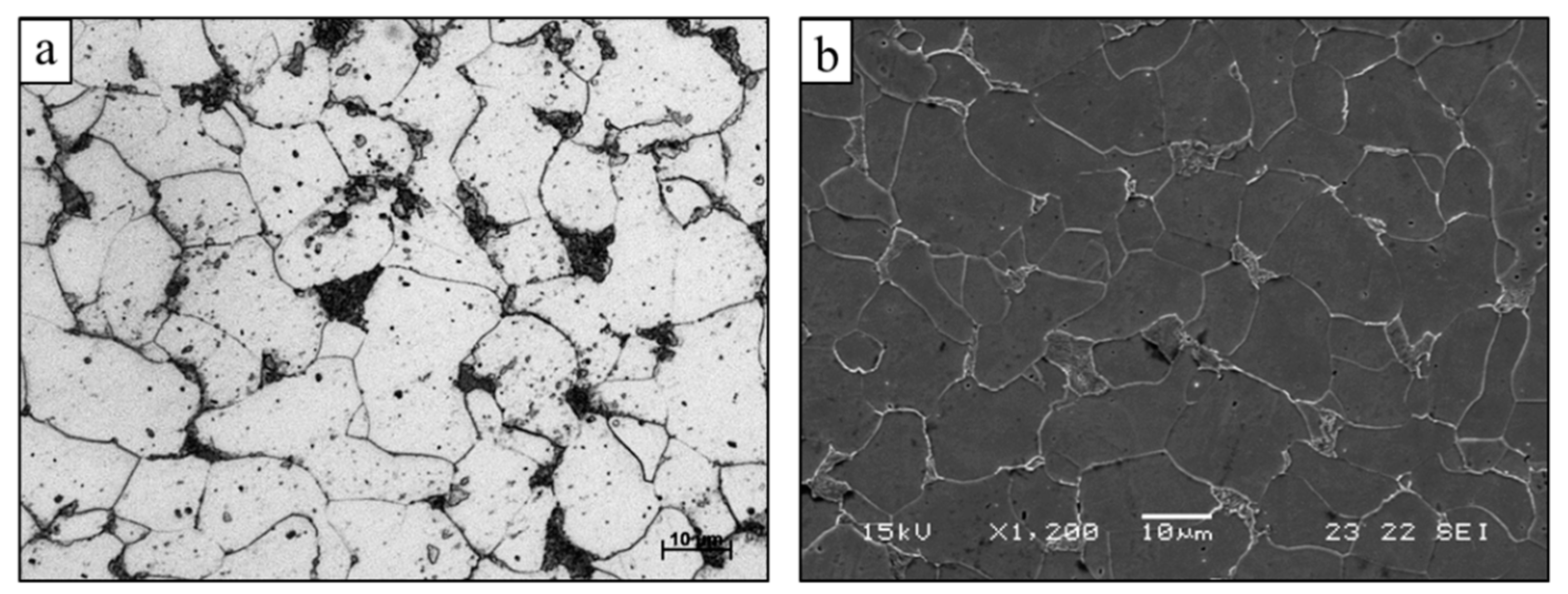
The microstructure of the ER70S-6 alloy in the XZ plane, as produced by the WAAM process, is shown in Figure 1. This reveals a typical microstructure of low carbon steel with a ferrite matrix and a relatively reduced amount of a secondary pearlite phase, as expected from the limited amount of carbon (0.072% C) and the rapid solidification conditions of the WAAM process [23]. In addition, clear inherent microstructural imperfections were present, as can be discerned in terms of porosity (0.15% by image analysis), impurities (0.08% by image analysis) and lack of fusion (0.04% by image analysis). All those defects can have a significantly detrimental effect on the mechanochemical behavior of the alloy, especially under cyclic loading conditions. The microstructure of the counterpart ST-37 alloy is shown in Figure 2, indicating that this alloy has a very similar microstructure with a relatively increased amount of secondary pearlite phase due to the higher content of carbon (0.15% C) present in this alloy.
The mechanical properties of an additively manufactured ER70S-6 alloy and its counterpart ST-37 alloy were measured in terms of tensile strength (475.7 ± 2.3 and 611.2 ± 12.9 MPa, respectively), elongation (34.6% ± 3.6% and 12.6% ± 0.2%, respectively) and hardness (192.4 ± 6 and 259.1 ± 15 HV, respectively) [23]. The relatively lower mechanical strength and increased ductility of the additively manufactured ER70S-6 alloy are mainly related to the increased content of carbon and subsequently increased amount of pearlite phase in the counterpart ST-37 alloy.
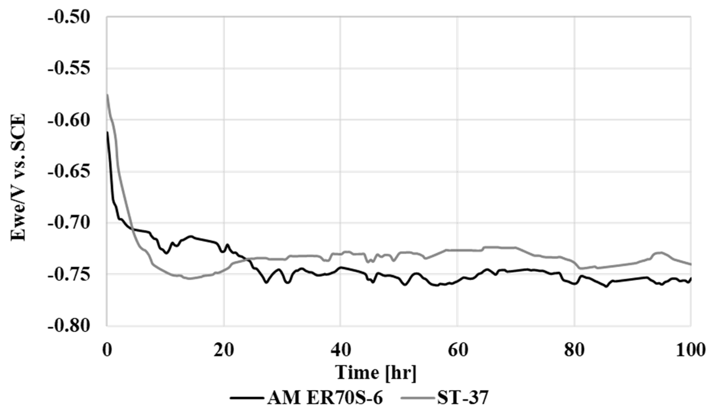
The outcomes of electrochemical examination of the additively manufactured ER70S-6 alloy and counterpart ST-37 alloy in terms of open circuit potential versus saturated calomel electrode (SCE) in a 3.5% NaCl solution are shown in Figure 3. This shows that the electrochemical tendencies of the two alloys were quite similar, although the stabilization (passivation phase) of the additively manufactured ER70S-6 alloy was obtained at a slightly higher potential. This result complies with the results of the immersion test and salt spray testing in the same corrosive environment as obtained by a previous study of the authors [23].
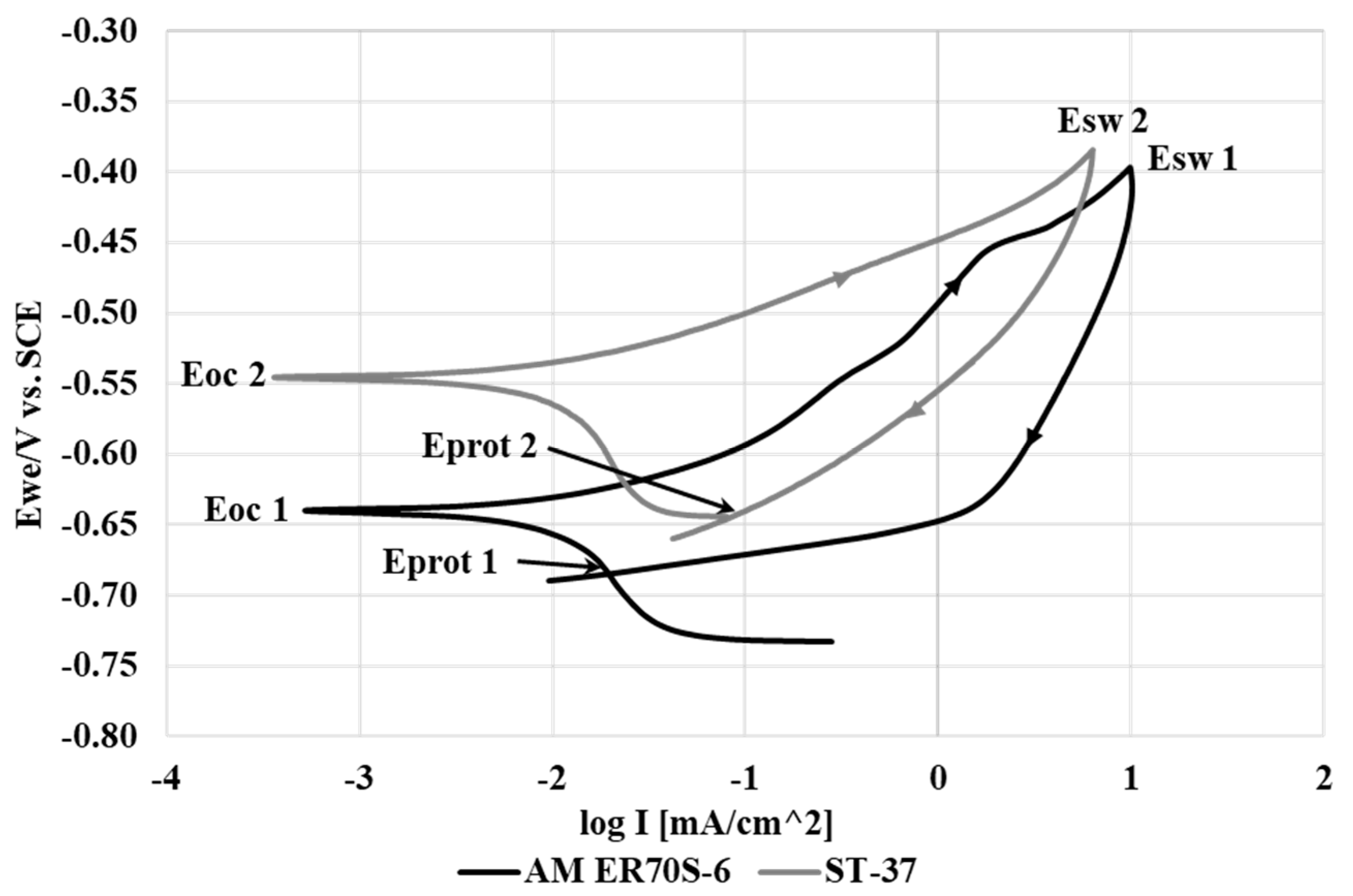
The cyclic potentiodynamic polarization analysis results for additively manufactured ER70S-6 alloy and its counterpart ST-37 alloy are shown in Figure 4. This reveals that the cyclic polarization curves of the two alloys were basically similar, without any tendency of one of the alloys to shift its polarization curve to higher current densities that could reflect significant differences in corrosion resistance [27,28]. In addition, the mode of the cyclic hysteresis of the two alloys after passing the Esw (switch) potential and reaching the Eprot (protection) potential was very similar. In both cases, the cyclic hysteresis mode represents a general/uniform corrosion attack. Tafel extrapolation measurements disclosed that the corrosion rate of the additively manufactured alloy was quite similar to that of the counterpart alloy (0.087 and 0.134 mmpy, respectively), which in both cases represents adequate corrosion resistance. Altogether, the results of the potentiodynamic polarization analysis agreed with the results obtained by the open circuit potential assessment.
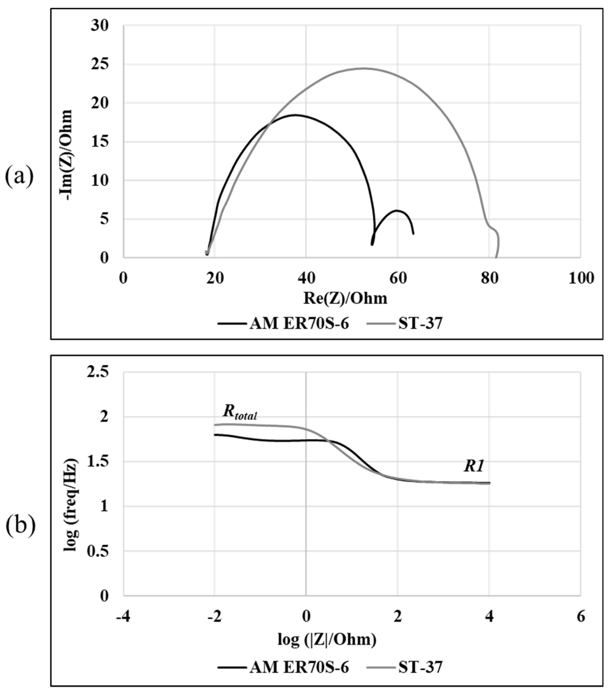
The results of the EIS analysis relating to the additively manufactured ER70S-6 and reference ST-37 alloys in terms of Nyquist plots and Bode plots are shown in Figure 5a,b. The Nyquist plots of both alloys were quite similar, with a small increase in the radius of the counterpart alloy that may illustrate a very minor improvement in the corrosion resistance. The Bode magnitude diagram that introduces the solution resistance (R1) and the total resistance of the system (Rtotal) clearly indicates that the corrosion resistances of the additively manufactured ER70S-6 alloy and reference ST-37 alloys were similar. The related electrical equivalent circuit, as well as the fitted parameters, are shown in Figure 6. The fitted parameters were: R1, solution resistance; R2 and C1 represent the double layer [29]; R3 and C2 represent the charge transfer resistance and capacitor [30].
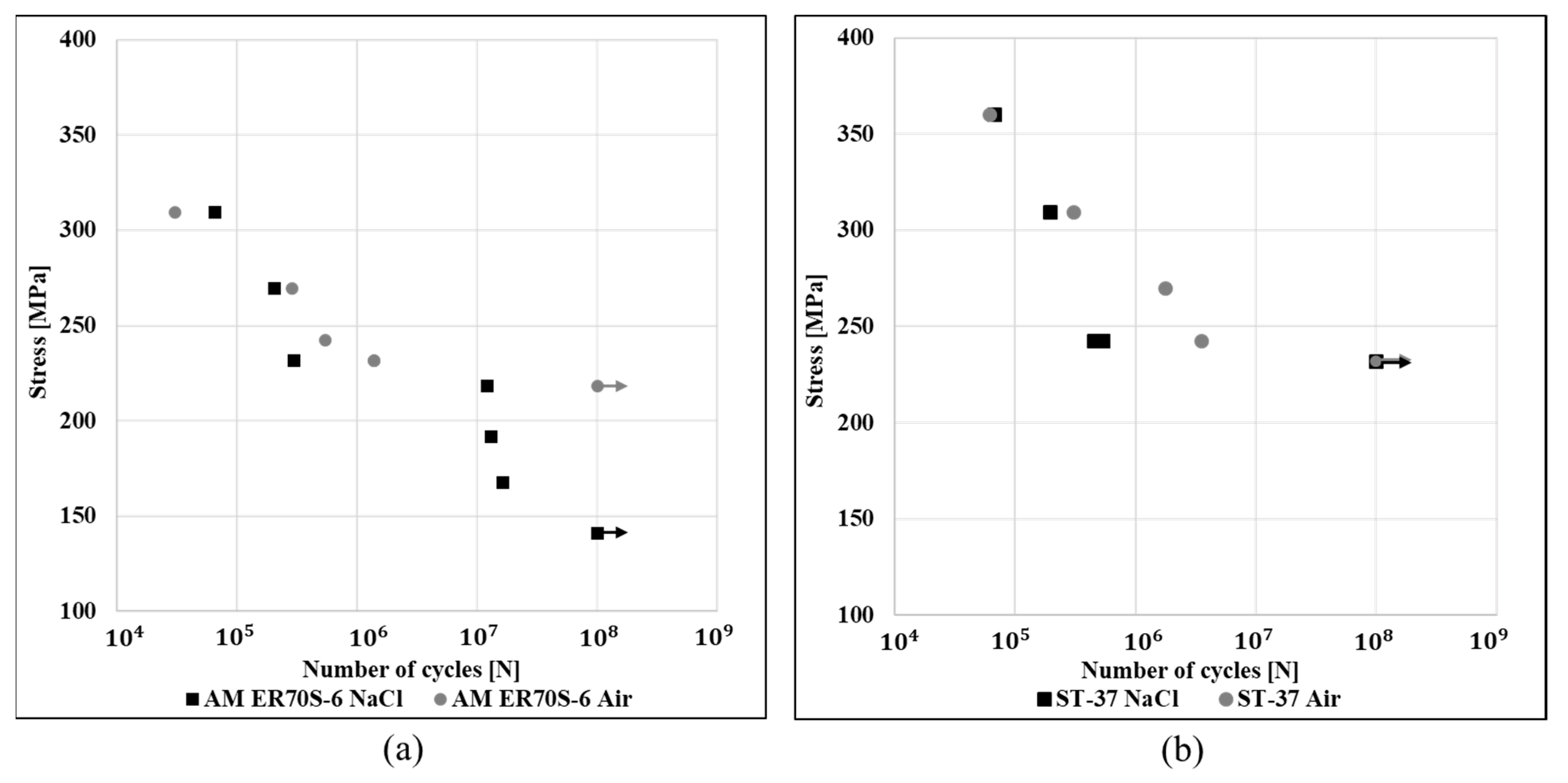
The high cycle fatigue strengths of additively manufactured ER70S-6 alloy and its counterpart ST-37 alloy, in air and in 3.5% NaCl solution, in terms of their S–N curves, are shown in Figure 7a,b. Although the shapes of the two S–N curves of both alloys in the air were quite similar, the fatigue strength of ER70S-6 alloy (220 MPa) was relatively reduced compared to that of the ST-37 alloy (230 MPa). This can mainly be attributed to the differences in carbon content, the amount of secondary phase and the subsequent mechanical properties of the two alloys. This explanation agrees with the results obtained by Tayanc et al. [31], who found that the fatigue strength of carbon steels increases as the carbon content is higher. In addition, it should be pointed out that both alloys had a clear endurance limit, which means that below a certain stress level, the two alloys will never fail due to cyclic loading alone [32]. In parallel, while the fatigue behavior of the counterpart ST-37 alloy was nearly unchanged by the transition from air to a corrosive environment, a dramatic modification was experienced by the additively manufactured ER70S-6 alloy. In this case, the fatigue strength of the additively manufactured alloy was reduced from 230 MPa in air to 140 MPa in the corrosive solution, and no endurance limit could be clearly identified.
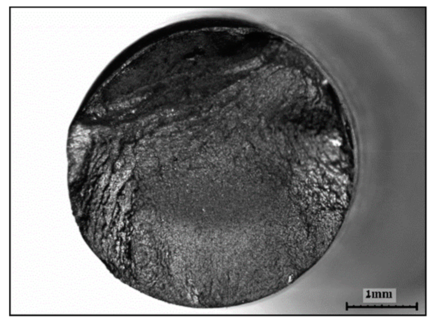
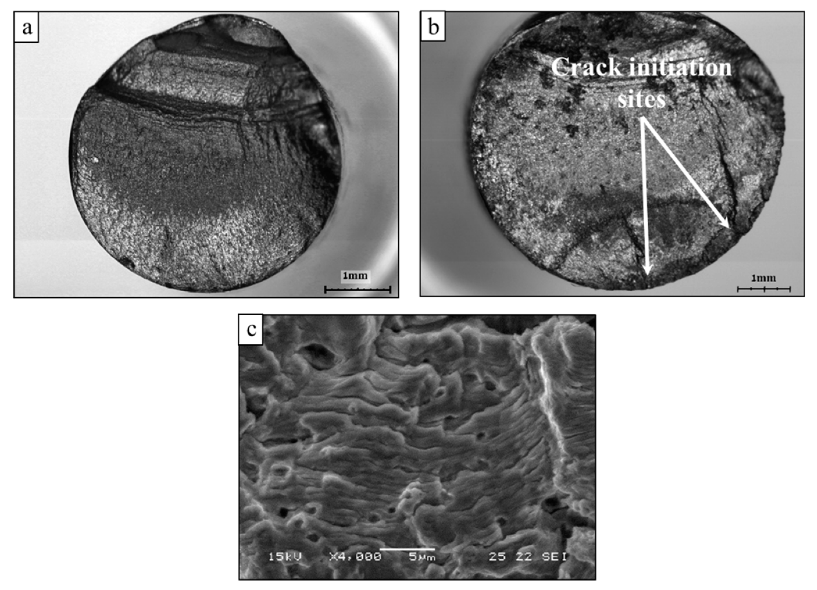
The fracture surface of ST-37 alloys after high cycle fatigue failure in an air atmosphere at a stress of 240 MPa is shown in Figure 8. The initial crack was produced at the external surface and slowly propagated across the material bulk in a direction perpendicular to the loading axis. As a result, the cross-sectional area was reduced to a point where it could not carry the load and the material failed in tension [32]. Consequently, the fracture surface of both alloys was basically divided into two main regions: the smooth regions where the crack propagation took place and the rough region where the final overload cracking occurred. However, the rough region of the additively manufactured ER70S-6 alloy (Figure 9a) was relatively enlarged compared to that of the counterpart ST-37 alloy. This could explain the increased number of cycles to failure (3,554,000 vs. 1,380,000 cycles) generated by the relatively increased strength of ST-37 alloy.
While the fracture surface characteristics of the ST-37 alloy after high cycle fatigue failure in 3.5% NaCl solution were quite similar to the results obtained in air, the fracture surface of the additively manufactured ER70S-6 alloy in the corrosive environment was significantly different from the results in air, as shown in Figure 9a,b. According to Figure 9b the fracture surface included three main areas: (i) a small smooth area with a crack initiation close to the south pole; (ii) a large smooth area at the center with an elongated crack initiation; and (iii) a rough area at the north pole that represents the final overload failure. The two smooth areas represent sections where natural crack propagation took place. However, it was evident that the cracking phenomena at the south pole included more than one crack initiation. It is believed that under the corrosive solution the inherent microstructural imperfections in the form of lack of fusion, impurities and porosity created favorable conditions for a localized corrosion attack. Consequently, those corrosive sites acted as an incubation phase for crack initiation and fatigue failure. Figure 9c shows a close-up view of the fracture surface that highlights the clear presence of porosity generated during the printing process.

4. Discussion

Although the corrosion resistance of the additively manufactured ER70S-6 alloy and its counterpart ST-37 alloy was quite similar in terms of their open circuit potential, potentiodynamic polarization, and electrochemical impedance spectroscopy analysis, their fatigue behavior in a 3.5% NaCl solution was significantly different. This was obtained in spite of the fact that their fatigue performance in an air atmosphere was relatively similar, apart from a minor difference created by an increased amount of carbon in the ST-37 alloy.
The main difference between the two alloys in terms of fatigue behavior in the corrosive solution was related to the fact that the fatigue strength of the additively manufactured alloy was significantly reduced compared to that of the counterpart ST-37 alloy. While the ST-37 alloy showed fatigue strength of 230 MPa and a clear endurance limit in the corrosive solution, the additively manufactured ER70S-6 alloy showed no endurance limit and continued to fail up to fatigue strength of 140 MPa (Figure 7). The fact that the definite endurance limit of the additively manufactured alloy obtained in air was lost due to its exposure to a corrosive environment is known as corrosion fatigue [32]. According to this phenomenon, the simultaneous action of fatigue loading and a corrosive environment can produce a localized corrosion attack such as pitting that subsequently generates stress corrosion sites that promote fatigue cracking. Following this insight, it is believed that the reason for the significant reduction in fatigue strength as well as the lack of a definite endurance limit of the additively manufactured alloy can be attributed to the inherent microstructural imperfections found in this material. These imperfections, in the form of porosity, impurities and lack of fusion, can act as corrosive sites that stimulate fatigue cracking. This assumption was also strongly supported by the results of the fracture surface analysis (Figure 9b) that showed multiple crack initiations from the external surface. The assumption that surface defects in steels can generate fatigue cracking that reduces the fatigue strength and, consequently, eliminates the definite endurance limit is already well known and understood [33,34,35].
In summary, the obtained results clearly demonstrate that the fatigue failure of an additively manufactured ER70S-6 alloy in air was purely mechanical, while in a 3.5% NaCl solution this failure was significantly affected by the corrosive environment which created the necessary conditions for corrosion fatigue. The corrosion fatigue failure was mainly attributed to the presence of microstructural imperfections produced during the WAAM process. The fact that the counterpart ST-37 alloy did not experience a reduction in the fatigue strength in the corrosive solution compared to its fatigue strength in air can be related to the absence of typical microstructural imperfections present in the additively manufactured ER70S-6 alloy. This was mainly related to imperfections such as lack of fusion and porosity that reasonably stimulate localized corrosion attack and consequent premature fatigue cracking.

5. Conclusions

In spite of the fact that the general corrosion performances, as well as the fatigue behaviors in air, of additively manufactured ER70S-6 and its counterpart ST-37 alloys, were quite similar, their fatigue behaviors in 3.5% NaCl solution were dramatically different. The fatigue strength of ST-37 alloy in the corrosive solution was maintained at 240 MPa with a definite endurance limit, while the additively manufactured ER70S-6 alloy showed fatigue strength of only 140 MPa. This was explained in terms the inherent microstructural imperfections present in the additively manufactured alloy in the form of porosity, impurities and lack of fusion that promote localized corrosion attacks and consequently stimulate fatigue cracking.

Author Contributions

E.A., A.S. and T.R. conceived, designed and performed the experiments; G.K.L., A.L. and O.D. assisted in analyzing the data; E.A. and T.R. wrote the paper. All authors have read and agreed to the published version of the manuscript.

Funding

This research received no external funding.

Conflicts of Interest

The authors declare no conflict of interest.

References

  1. Rodrigues, T.A.; Duarte, V.; Avila, J.A.; Santos, T.G.; Miranda, R.M.; Oliveira, J.P. Wire and arc additive manufacturing of HSLA steel: Effect of thermal cycles on microstructure and mechanical properties. Addit. Manuf. 2019, 27, 440–450. [Google Scholar] [CrossRef]
  2. Rodrigues, T.A.; Duarte, V.; Miranda, R.M.; Santos, T.G.; Oliveira, J.P. Current status and perspectives on wire and arc additive manufacturing (WAAM). Materials 2019, 12, 1121. [Google Scholar] [CrossRef] [PubMed] [Green Version]
  3. Zakay, A.; Aghion, E. Effect of post-heat treatment on the corrosion behavior of AlSi10Mg alloy produced by additive manufacturing. JOM 2019, 71, 1150–1157. [Google Scholar] [CrossRef]
  4. Leon, A.; Shirizly, A.; Aghion, E.; Leon, A.; Shirizly, A.; Aghion, E. Corrosion behavior of AlSi10Mg alloy produced by additive manufacturing (AM) vs. its counterpart gravity cast alloy. Metals 2016, 6, 148. [Google Scholar] [CrossRef]
  5. Hosseini, V.A.; Högström, M.; Hurtig, K.; Bermejo, M.A.V.; Stridh, L.E.; Karlsson, L. Wire-arc additive manufacturing of a duplex stainless steel: Thermal cycle analysis and microstructure characterization. Weld. World 2019, 63, 975–987. [Google Scholar] [CrossRef] [Green Version]
  6. Donoghue, J.; Antonysamy, A.A.; Martina, F.; Colegrove, P.A.; Williams, S.W.; Prangnell, P.B. The effectiveness of combining rolling deformation with Wire–Arc Additive Manufacture on β-grain refinement and texture modification in Ti–6Al–4V. Mater. Charact. 2016, 114, 103–114. [Google Scholar] [CrossRef]
  7. Wu, B.; Pan, Z.; Ding, D.; Cuiuri, D.; Li, H.; Xu, J.; Norrish, J. A review of the wire arc additive manufacturing of metals: Properties, defects and quality improvement. J. Manuf. Process. 2018, 35, 127–139. [Google Scholar] [CrossRef]
  8. Ge, J.; Ma, T.; Chen, Y.; Jin, T.; Fu, H.; Xiao, R.; Lei, Y.; Lin, J. Wire-arc additive manufacturing H13 part: 3D pore distribution, microstructural evolution, and mechanical performances. J. Alloys Compd. 2019, 783, 145–155. [Google Scholar] [CrossRef]
  9. Wang, L.; Xue, J.; Wang, Q. Correlation between arc mode, microstructure, and mechanical properties during wire arc additive manufacturing of 316L stainless steel. Mater. Sci. Eng. A 2019, 751, 183–190. [Google Scholar] [CrossRef]
  10. Bekker, A.C.M.; Jouke, C.V.; Giorgia, G. Challenges in assessing the sustainability of wire+ arc additive manufacturing for large structures. In Proceedings of the Solid Freeform Fabrication Symposium–An Additive Manufacturing Conference, Austin, TX, USA, 8–10 August 2016. [Google Scholar]
  11. Cunningham, C.R.; Wikshåland, S.; Xu, F.; Kemakolam, N.; Shokrani, A.; Dhokia, V.; Newman, S.T. Cost modelling and sensitivity analysis of wire and arc additive manufacturing. Procedia Manuf. 2017, 11, 650–657. [Google Scholar] [CrossRef]
  12. Caballero, A.; Ding, J.; Ganguly, S.; Williams, S. Wire + Arc Additive Manufacture of 17-4 PH stainless steel: Effect of different processing conditions on microstructure, hardness, and tensile strength. J. Mater. Process. Technol. 2019, 268, 54–62. [Google Scholar] [CrossRef]
  13. Xu, X.; Ding, J.; Ganguly, S.; Diao, C.; Williams, S. Preliminary investigation of building strategies of maraging steel bulk material using wire + arc additive manufacture. J. Mater. Eng. Perform. 2019, 28, 594–600. [Google Scholar] [CrossRef]
  14. Leon, A.; Aghion, E. Effect of surface roughness on corrosion fatigue performance of AlSi10Mg alloy produced by selective laser melting (SLM). Mater. Charact. 2017, 131, 188–194. [Google Scholar] [CrossRef]
  15. Zhang, C.; Li, Y.; Gao, M.; Zeng, X. Wire arc additive manufacturing of Al-6Mg alloy using variable polarity cold metal transfer arc as power source. Mater. Sci. Eng. A 2018, 711, 415–423. [Google Scholar] [CrossRef]
  16. Lin, Z.; Goulas, C.; Ya, W.; Hermans, M.J.M. Microstructure and mechanical properties of medium carbon steel deposits obtained via wire and arc additive manufacturing using metal-cored wire. Metals 2019, 9, 673. [Google Scholar] [CrossRef] [Green Version]
  17. Gu, D. Laser Additive Manufacturing (AM): Classification, Processing Philosophy, and Metallurgical Mechanisms. In Laser Additive Manufacturing of High-Performance Materials; Springer: Heidelberg/Berlin, Germany, 2015; pp. 15–71. [Google Scholar]
  18. Lockett, H.; Ding, J.; Williams, S.; Martina, F. Design for wire + arc additive manufacture: Design rules and build orientation selection. J. Eng. Des. 2017, 28, 568–598. [Google Scholar] [CrossRef] [Green Version]
  19. Derekar, K.S. A review of wire arc additive manufacturing and advances in wire arc additive manufacturing of aluminium. Mater. Sci. Technol. 2018, 34, 895–916. [Google Scholar] [CrossRef]
  20. Ghaffari, M.; Nemani, A.V.; Rafieazad, M.; Nasiri, A. Effect of solidification defects and HAZ softening on the anisotropic mechanical properties of a wire arc additive-manufactured low-carbon low-alloy steel part. JOM 2019, 71, 4215–4224. [Google Scholar] [CrossRef]
  21. Gordon, J.; Hochhalter, J.; Haden, C.; Harlow, D.G. Enhancement in fatigue performance of metastable austenitic stainless steel through directed energy deposition additive manufacturing. Mater. Des. 2019, 168. [Google Scholar] [CrossRef]
  22. Fadaei, A.; Mokhtari, H. Finite element modeling and experimental study of residual stresses in repair butt weld of ST-37 plates. Iran. J. Sci. Technol. Trans. Mech. Eng. 2015, 39, 291–307. [Google Scholar]
  23. Ron, T.; Levy, G.K.; Dolev, O.; Leon, A.; Shirizly, A.; Aghion, E. Environmental behavior of low carbon steel produced by a wire arc additive manufacturing Process. Metals 2019, 9, 888. [Google Scholar] [CrossRef] [Green Version]
  24. Shirizly, A.; Dolev, O. From wire to seamless flow-formed tube: Leveraging the combination of wire arc additive manufacturing and metal forming. JOM 2019, 71, 709–717. [Google Scholar] [CrossRef] [Green Version]
  25. Kaya, A.A.; Uzan, P.; Eliezer, D.; Aghion, E. Electron microscopical investigation of as cast AZ91D alloy. Mater. Sci. Technol. 2000, 16, 1001–1006. [Google Scholar] [CrossRef]
  26. Elkaiam, L.; Hakimi, O.; Goldman, J.; Aghion, E. The effect of Nd on mechanical properties and corrosion performance of biodegradable Mg-5%Zn alloy. Metals 2018, 8, 438. [Google Scholar] [CrossRef] [Green Version]
  27. Itzhak, D.; Aghion, E. Corrosion behaviour of hot-pressed austenitic stainless steel in H2SO4 solutions at room temperature. Corros. Sci. 1983, 23, 1085–1094. [Google Scholar] [CrossRef]
  28. Itzhak, D.; Aghion, E. An anodic behaviour study of an analogical sintered system of austenitic stainless steel in H2SO4 solution. Corros. Sci. 1984, 24, 145–149. [Google Scholar] [CrossRef]
  29. Kafri, A.; Ovadia, S.; Goldman, J.; Drelich, J.; Aghion, E. The suitability of Zn–1.3%Fe alloy as a biodegradable implant material. Metals 2018, 8, 153. [Google Scholar] [CrossRef] [Green Version]
  30. Gerengi, H.; Uygur, I.; Solomon, M.; Yildiz, M.; Goksu, H. Evaluation of the inhibitive effect of Diospyros kaki (Persimmon) leaves extract on St37 steel corrosion in acid medium. Sustain. Chem. Pharm. 2016, 4, 57–66. [Google Scholar] [CrossRef]
  31. Tayanç, M.; Aytaç, A.; Bayram, A. The effect of carbon content on fatigue strength of dual-phase steels. Mater. Des. 2007, 28, 1827–1835. [Google Scholar] [CrossRef]
  32. Campbell, E.; Flake, C. Elements of Metallurgy and Engineering Alloys; Chapter 14, Fatigue; ASM International: Cleveland, OH, USA, 2008. [Google Scholar]
  33. Sonsino, C.M. Course of SN-curves especially in the high-cycle fatigue regime with regard to component design and safety. Int. J. Fatigue 2007, 29, 2246–2258. [Google Scholar] [CrossRef]
  34. Naito, T.; Ueda, H.; Kikuchi, M. Fatigue behavior of carburized steel with internal oxides and nonmartensitic microstructure near the surfsace. Metall. Trans. A 1984, 15, 1431–1436. [Google Scholar] [CrossRef]
  35. Mutoh, Y.; Tanaka, K. Fretting fatigue in several steels and a cast iron. Wear 1988, 125, 175–191. [Google Scholar] [CrossRef]
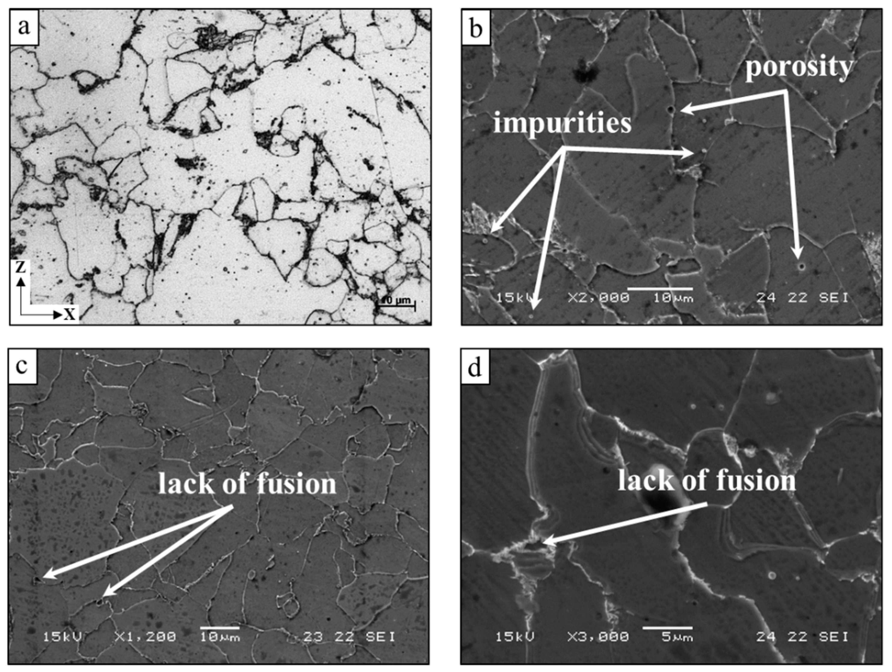
Figure 1. Typical microstructures of additively manufactured ER70S-6 alloy in the XZ plane: (a) optical microscopy; (bd) scanning electron microscopy.
Metals 10 00098 g001
Figure 2. Typical microstructure of the counterpart ST-37 alloy: (a) optical microscopy; (b) scanning electron microscopy.
Metals 10 00098 g002
Figure 3. Open circuit potential of additively manufactured ER70S-6 alloy and counterpart ST-37 alloy in 3.5% NaCl solution.
Metals 10 00098 g003
Figure 4. Cyclic potentiodynamic polarization analysis of additively manufactured ER70S-6 alloy and reference ST-37 alloys in 3.5% NaCl solution.
Metals 10 00098 g004

AM ER70S-6ST-37
Ecorr (V)−0.65 ± 0.002−0.56 ± 0.03
Icorr (μA)6.12 ± 0.66.6 ± 0.7
Corrosion rate (mmpy)0.13 ± 0.010.08 ± 0.01
Figure 5. Electrochemical impedance spectroscopy of additively manufactured ER70S-6 alloy and reference ST-37 alloys in 3.5% NaCl solution: (a) Nyquist diagram; (b) Bode magnitude diagram.
Metals 10 00098 g005
Figure 6. Electrical equivalent circuit and related fitted parameters for Nyquist and Bode diagrams plots shown in Figure 5.
Metals 10 00098 g006

R1 [Ohm]C1 [F]R2 [Ohm]C2 [F]R3 [Ohm]
AM ER70S-618.322.55∙10−46.312.44∙10−431.98
ST-3718.654.13∙10−418.861.14∙10−342.15
Figure 7. S–N curve obtained in air and in 3.5% NaCl solution for (a) additively manufactured ER70S-6 alloy and (b) counterpart ST-37 alloy.
Metals 10 00098 g007
Figure 8. Fractography analysis of ST-37 alloy after high cycle fatigue failure in air, with 240 MPa load and 3,554,000 cycles.
Metals 10 00098 g008
Figure 9. Fractography analysis of additively manufactured ER70S-6 alloy after high cycle fatigue failure (a) in air, with 230 MPa load and 1,380,000 cycles; (b,c) in 3.5% NaCl solution, with 220 MPa load and 11,987,000 cycles.
Metals 10 00098 g009