Article

Investigation of the Restored Joint for Aluminum Alloy

1
State Key Laboratory of High Performance Complex Manufacturing, Light Alloy Research Institute, Central South University, Changsha 410083, China
2
School of Mechanical and Electrical Engineering, Central South University, Changsha 410083, China
*
Author to whom correspondence should be addressed.
Metals 2020, 10(1), 97; https://doi.org/10.3390/met10010097
Submission received: 7 December 2019 / Revised: 25 December 2019 / Accepted: 27 December 2019 / Published: 7 January 2020

Abstract

:
In recent years, the mechanical clinching method plays an increasingly important role in the building of thin-walled structures. The clinched joint can be employed to join the lightweight materials. Compared with other joining methods, the clinched joint has better mechanical behavior. However, the clinched joint may be deformed during use when it bears a high shear force. In this research, a process to join aluminum alloy and restore deformed joint was proposed and investigated. The clinched joint was deformed in the deforming process. Then, a customized rivet and two flat restoring tools were utilized for restoring the deformed joint to join aluminum alloy. Different restoring forces such as 45, 40, 35, 30, 25, and 20 kN were employed to produce diverse restored joints. Some shearing tests on the restored joint were utilized for understanding joint material flow, mode of failure, thickness of neck, shear strength, and absorption of energy. The thickness of neck can be increased in restoring process, which contributes to improve the shear strength. The rivet embedded in a pit also helps restored joint bear shear force, so all of the restored joints have higher absorption of energy and shear strength than the clinched joints. The restoring process effectively restores the deformed joint to obtain better mechanical behavior.

1. Introduction

With the development of lightweight structures, more and more light materials such as titanium alloy and aluminum alloy are utilized for building lightweight structures [1,2,3]. The joining of light materials is an important issue in the realm of joining technology [4]. Welding technique is a widely used joining technology to build the automotive structure. However, because of high thermal conductivity, the natural surface oxide layer, and other problems, it is hard for the welding technique to connect the light materials [5]. In addition, spark and smoke produced during the welding process is not environmentally friendly [6].
Self-pierce riveting is one of the mechanical joining technologies which are suitable for joining light materials [7,8,9]. The sheets joined by self-pierce riveting technology can gain a high static strength. However, the customized rivet can impale the upper sheet in joining process, which may damage the upper sheet [10]. With the upper sheet damaged, the riveted joint may be corroded easily. The rivet applied in joining process also can add the weight of the joint, which is inappropriate for achieving the lightweight structures. In addition, a higher joining force needed during self-pierce riveting process consumes more energy.
Mechanical clinching is another mechanical joining technology [11]. There is a huge difference between clinching and self-pierce riveting, and the biggest difference is that mechanical clinching does not use rivet [12]. The cost and weight of the joint can be reduced because there is no extra rivet. Compared with the welding technique, spark and smoke are not produced during the clinching process. Therefore, mechanical clinching is more environmentally friendly [13].
With the sheets plastic deformation generated, the interlock produced between the sheets is able to hook the upper and lower sheets together, which makes clinched joint get a high strength [14,15,16,17]. The clinching process using extensible dies can be divided into four phases: (a) localized plastic deformation of the sheets, (b) drawing, (c) radial material flowing, and (d) indirect extrusion.
The profile of produced joint performs an essential role in improving the clinched joint mechanical behavior [8]. The clinching tools, mechanical behavior of materials, process parameters, and other conditions are able to determine the profile of the joint [18,19,20]. Many researchers have conducted in-depth research on the clinching tools design. Oudjene et al. used the response surface methodology to optimize the clinching tools with Moving Least-Square approximation [21]. The clinched joints resistance to tensile load was improved by optimizing the geometries of the die and the punch. A design method of clinching tools proposed by Lee et al. can satisfy the required clinched joint strength well [22]. Finite element analysis and experimental test were implemented to get the optimal clinching tools. Lambiase and Di Ilio investigated the mechanical properties of the clinched joints produced by extensible dies and fixed dies with different forming forces respectively [23]. The clinched joint with extensible dies has better mechanical properties in the strength and energy absorption during peeling tests than the clinched with fixed dies.
Mucha investigated the effect of the process parameters on the joining of advanced high-strength steel using clinching method [24]. The clinching tool used in his study is the fixed die. Lambiase investigated the influence of process parameters in mechanical clinching using extensible dies [25]. Die depth, die corner radius, die diameter, punch corner radius, and the punch diameter were taken as the main research contents. Oudjene and Ben-Ayed implemented a parametrical research of mechanical clinching. Taguchi method was employed to join metal sheets [26]. He et al. investigated the deformation of clinched joint with extensible dies by using numerical analysis and experimental tests [27]. Good agreement was achieved between the numerical predictions and the experimental results.
The mechanical clinching technology can also join different materials together. Lambiase et al. researched the mechanical joining of aluminum sheets with carbon fiber reinforced polymer sheets and glass fiber reinforced polymer [28,29]. The mechanical clinching technology can join metal sheets with the polymer sheet together [30,31,32]. Jiang et al., Abe et al., and other researchers investigated the joining of steel sheet with aluminum alloy sheet [33,34,35,36]. Xing et al. investigated the mechanical properties of the clinched joint with copper alloy H62 sheet [37]. He et al. used mechanical clinching technology to join titanium sheet materials [38]. The titanium sheets can be joined together with a high strength.
Many researchers also investigated failure behavior of the clinched joint. Zhao et al. implement numerical and experimental research on the failure behavior of the clinched joint with a modified Rousselier model [39]. Xu et al. simulated the failure behavior of clinched joint with aluminum alloy sheets by using a modified Gurson model [40]. Lambiase and Di Ilio built a numerical model to predict the onset of fracture in the mechanical clinching process for joining aluminum alloy sheets [41].
There may be some shear forces applied to the clinched joint during use. The joint may be deformed when it bears a higher shear force. With a deformed part, the strength of clinched joint may be reduced, which may result in accidents. Now, there is no restoring technology for the deformed joint to help it restore to its original shape. Some restoring technologies to repair the deformed joint should be explored and investigated in order to guarantee the safety of the joint.
In this research, a technology to restore the deformed joint was proposed and investigated. A customized rivet and two flat tools were utilized for restoring the deformed joint in a single stroke. Different restoring forces were used to produce diverse restored joints. Some shearing tests on the restored joint were utilized for understanding joint material flow, mode of failure, thickness of neck, shear strength, and absorption of energy. The restored joint has higher mechanical behavior than the clinched joint.

2. Mechanism

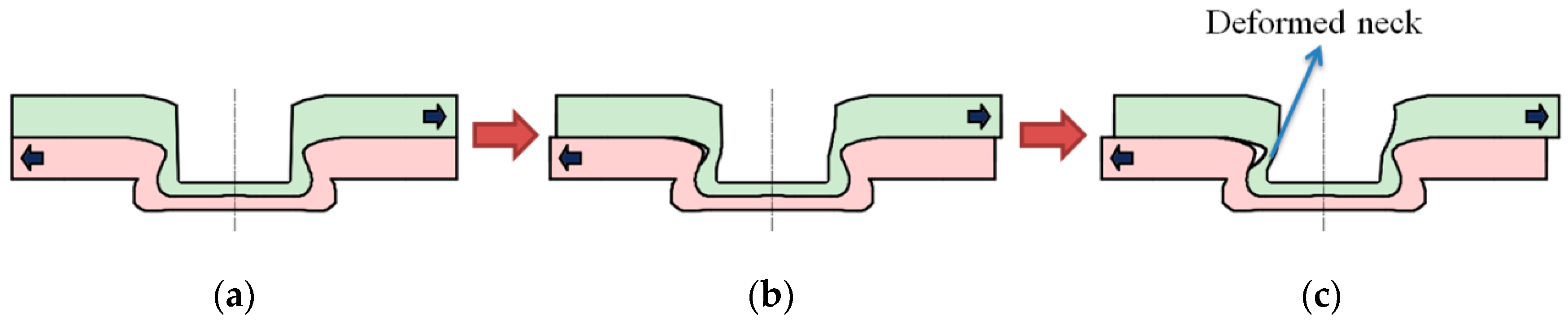
2.1. Mechanism of the Deforming Process

The clinched joint may be deformed when high shear strength is applied on the joint. The clinched joint bearing a shear force on the lower sheet and upper sheet is shown in Figure 1. The direction of the shear force is shown by the black arrow. The neck area of the joint bears most of the shear force with the interlock hooking the sheets together. A high shear force may generate a long displacement of the joint. If the displacement of the joint exceeds the limitation of elastic deformation, the clinched joint may be deformed plastically. With plastic deformation, the joint cannot be restored to its original shape after the shear force is released, which may decrease the strength of the joint.

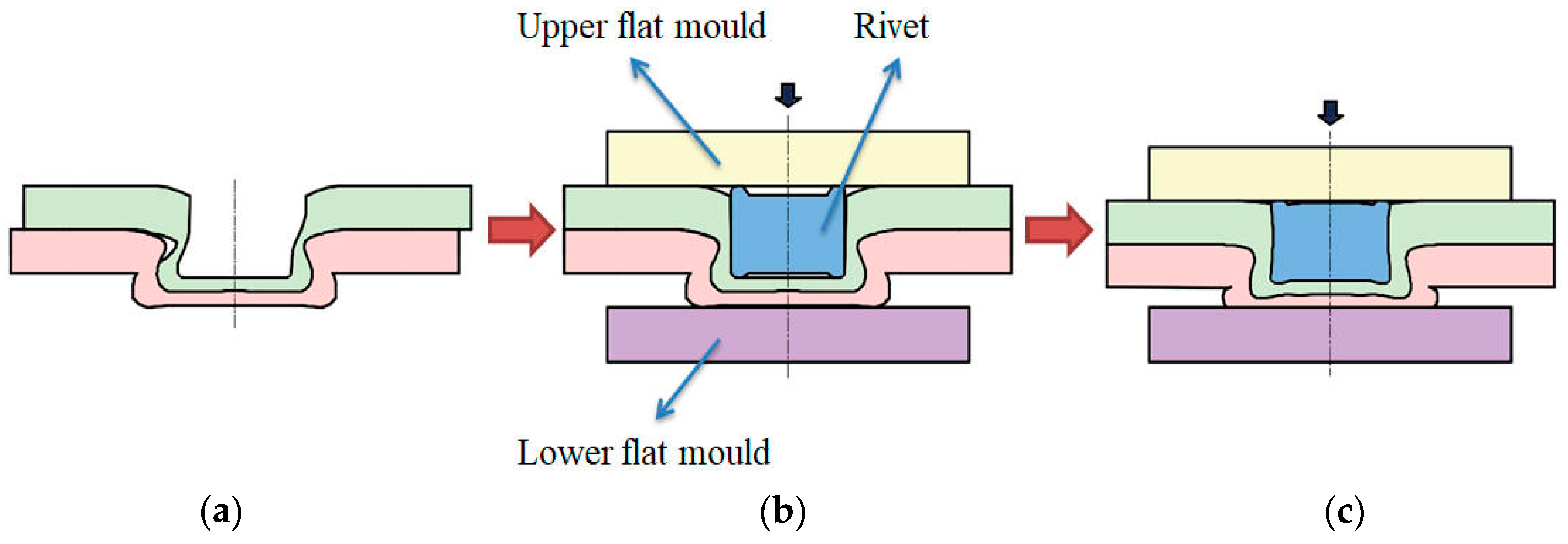
2.2. Mechanism of the Restoring Process

The deformed joint cannot be used because of the decreased strength. A process is carried out to help the deformed joint restore to its original shape as shown in Figure 2. The direction of the restoring force is shown by the black arrow. The deformed neck can be reshaped by the rivet embedded in the deformed joint pit. Two flat dies are employed to compress the protrusion of the joint, which also can generate plastic deformation on the rivet. The deformed neck can be restored to its original shape with the help of the deformed rivet. With a restored neck, the joint can be used continuously with a high strength. The protrusion material is also compressed to flow upward and radially during the restoring process. The upward flow of material can enlarge the neck of the restored joint.

3. Procedure of Experiments

3.1. Materials

In this study, the mechanical clinching process was employed to join Al5052 sheets. Al5052 sheets have good forming properties, which are suitable for constructing the automobile body. The width of the specimen is 25 mm, the nominal thickness is 1.9 mm, and the length is 80 mm. A large Al5052 sheet was cut into many identical quadrate sheets along the rolling direction. The Instron 5982 tensile testing equipment can measure and record the mechanical properties of the Al5052 sheets. Based on the results of the measurement, Al5052 sheets have an elongation at break of 18%, an elastic modulus of 62.7 GPa, and a tensile strength of 235.2 MPa.

3.2. Mechanical Clinching Process

The mechanical clinching process can be implemented by the clinching equipment manufactured by Express Corporation. The mechanical clinching process can be employed to produce the clinched joint. Fixed dies consist of a punch and an anvil, while extensible dies consist of a punch, some sliding sectors, and an anvil. The sliding sectors are helpful to guide the material flow. Comparing with the clinched joint using fixed dies, the clinched joint with extensible dies has higher strength and energy absorption during peeling tests because of a larger interlock. In this research, the extensible dies were employed as main clinching tools. The components of the extensible dies are punch, sliding sectors, anvil, and other components. The shape of the extensible die is shown in Figure 3. The punch made of die block steel was utilized for compressing the sheets, which can generate an interlock between the lower and upper sheets. The sliding sectors and anvil were utilized for guiding the radial material flow. The velocity of the punch was 30 mm/min in the whole clinching process.

3.3. Deforming Process

The clinched joint may be deformed or damaged during the use. The deforming process is utilized for making the clinched joint deformed. The specimen employed for deforming process is shown in Figure 4. Shear forces are applied on the upper and lower sheets to pull the clinched joint. The clinched joint was located on the central overlapping region. The Instron 5982 testing equipment (Instron Company, Grove City, PA, USA) was employed to implement the deforming process. The velocity of the deforming process was 2 mm/min. The testing equipment can accurately measure and record the deforming force-displacement curve. When the deforming force reaches 1200 N after the maximum force peak, the testing machine was controlled to stop. Then, the deformed joint can be produced with a deformed neck.

3.4. Restoring Process

Restoring process was used to restore the deformed joint. The restoring tools and the customized rivet are shown in Figure 5. After the rivet was embedded in the joint pit, the deformed joint was placed between the restoring tools. The deformed joint was compressed by the upper flat die moving downward. Under the motion of the upper flat die, the rivet was also deformed. With the help of the rivet, the deformed neck of the joint could restore to its original shape. The velocity of the upper flat die was 3 mm/min in the whole restoring process. So as to research the effect of the restoring force on mechanical behavior of restored joint, different restoring forces such as 45, 40, 35, 30, and 25 kN, respectively, were used to restore the deformed joint in this study.

3.5. Static Shearing Test

So as to assess the clinched joint quality, the shear strength is used as a vital evaluation criterion. The shear specimen is shown in Figure 6. The static shearing tests were implemented by Instron 5982 testing equipment. The testing equipment can detect the maximum shear force as the clinched joint shear strength. The testing equipment also can measure and record the shear force-displacement curve. The velocity of the shearing test was 2 mm/min. The specimen used in the deforming process was similar to that used in the static shearing test. To ensure the accuracy of the data, the average shear strength for each joining type should be obtained from the results of the five tests.
Absorption of energy is another vital evaluation criterion for the clinched joint. In the failure process, the clinched joint can absorb more energy, which is better for the automotive body to bear more impact. The areas between the shear force-displacement curve and abscissas can be measured to get the joint absorption of energy.

4. Results and Discussion

4.1. Material Flow

The deformed joint was compressed with different forces in the restoring process. The rivet was also compressed to generate plastic deformation. The deformed neck can be restored to its original shape with the help of the deformed rivet. As shown in Figure 7, the cross-sectional profiles of the different joints are used to show the material flow with different restoring forces. In order to make the contrast more obvious, the same figure shows the deformed joint and the restored joint. The deformed joint is the left cross-sectional profile of each figure, and the restored joint is the right cross-sectional profile of each figure. There was a small displacement generated between the upper and lower sheets along radial direction in deforming process, which resulted in the plastic deformation of the neck area. The displacement also resulted in an obvious gap between the upper and lower sheets near the deformed neck.
As seen in Figure 7, the interlock can continue to work in the restoring process and can still hook the upper and lower sheets together. Compared with the deformed joint neck, the restored joint neck restored to its original shape in restoring process.
The clinched joint neck was deformed in deforming process. With the neck deformed, the mechanical behavior of the joint may be affected. The customized rivet was embedded in the deformed joint pit, and the deformed joint protrusion was compressed by the upper flat die moving downward. With the upper flat die compressing the deformed joint, the joint protrusion height was also decreased during restoring process. The deformed joint protrusion could generate serious plastic deformation. There were some materials compressed to flow upward, which may raise the joint neck thickness. In addition, there were some materials compressed to radial flow, which could raise the protrusion diameter.
The extensible dies used three sliding sectors which could generate a coarse protrusion. By compressing the joint protrusion with the flat dies, the protrusion can become flat. The restoring force can reduce the clinched joint protrusion height and can make the surface of the protrusion become flat, as shown in Figure 8.

4.2. Mode of Failure

For the clinched joint, there are two representative modes of failures: the mode of neck fracture and the mode of button separation. If the neck can withstand a larger force than the mechanical interlock, the joint may lose effectiveness as the mode of button separation under a larger force. If the mechanical lock can withstand a larger force than the neck, the joint may lose effectiveness as the mode of neck fracture under a larger force.
Because of the mode of neck fracture, all of the clinched joints lost effectiveness in this research. The neck of the clinched joint fractured in shear test is shown in Figure 9. The bottom part of the upper sheet was kept in the pit of the lower sheet under the action of the interlock.
As for the restored joint, the mode of neck fracture was also the main mode of failure in this research. The neck of the restored joint fractured under the high shear force is shown in Figure 10. The upper sheet took away the rivet, and the bottom part of upper sheet was kept in the pit of the lower sheet. The mode of restored joint failure was the same as the mode of clinched joint failure.

4.3. Thickness of Neck

The mode of neck fracture was the main mode of failure for joints in this experiment, which implies the thickness of joint neck plays an indispensable role in the joint shear strength. With a high shearing force applied on the clinched joint, the clinched joint neck could generate a severe plastic deformation. The thicknesses of the deformed joint and clinched joint necks were shown in Figure 11. The thickness of deformed joint neck is lower than the thickness of clinched joint neck. The thickness of neck was reduced in the deforming process. The shear force was principally applied on the neck in deforming process, so the neck of joint could generate plastic deformation. With the thickness of neck reduced, the mechanical behavior of the joint may also be affected.
As shown in Figure 12, a series of restoring forces employed on the restored joint can generate different thicknesses of joint neck. Comparing with the clinched joints, all of the deformed joints have a lower thickness of neck. The restoring process not only can restore the deformed neck, but also can increase the thickness of neck.
The restored joint using the 40 kN restoring force has the largest thickness of neck. Before the restoring force of 40 kN, when the restoring force was raised, the thickness of neck was increased. The protrusion height was reduced when the restoring force was raised. The protrusion material flowed to the joint neck area, which could increase the thickness of neck. Therefore, with the raise of the restoring force, the thickness of neck was raised. As shown in Figure 13, after the 40 kN restoring force and with the raise of the restoring force, the thickness of neck was reduced. Under the action of a higher restoring force, the rivet embedded in the deformed joint pit was also compressed to deform severely. By compressing the rivet, the height of the rivet was decreased, and the diameter of the rivet was increased. The increase of the rivet diameter might compress the neck area, which would decrease the thickness of neck. Therefore, when the restoring force was raised, the neck thickness was decreased.

4.4. Shear Strength

Five specimens of clinched joint were tested in the shear strength test, which could gain the average shear strength. The average clinched joint shear strength is 1673.8 N. Five specimens of restored joint for each restoring force case were tested in the shear strength test. Corresponding, 25 specimens of the restored joint were tested in the shear strength test, which could gain five average shear strengths. The shear strengths of the restored joints using a series of restoring forces are shown in Figure 14. The developing trend of shear strength is similar with that of neck thickness. For the clinched and restored joints in this research, the thickness of neck performs an indispensable role in the joint shear strength. Comparing with the restored joint, all the clinched joints have lower shear strength. The rivet embedded in the restored joint pit helps the joint to bear shear force, which contributes to raise the restored joint shear strength.
The restored joint using the 40 kN restoring force has the highest shear strength, and the restored joint using the 25 kN restoring force has the lowest shear strength. The shear strength of the restored joint using the 40 kN restoring force is raised by 118.2% than the clinched joint. The restored joint can bear a higher load under the action of higher shear strength. The restoring process can improve the mechanical behavior of the joint. If the joint is deformed under a higher shear strength, it is better to repair the deformed joint using the restoring technology to enhance mechanical behavior of the joint.
As shown in Figure 15, the joints after restoring processes have different shear force-displacement curves. All of shear force-displacement curves of the different joints have the similar developing trend. Before the maximum shear force peak, when the displacement is enlarged, the shear force is raised gradually. After the maximum shear force peak, when the displacement is enlarged, the shear force is decreased gradually.

4.5. Absorption of Energy

Absorption of energy is one of the vital clinched joint evaluation criterions. For instance, if there is a collision between two cars, the more impact energy automotive body absorbs, the more safety the driver has. Thus, the mechanical clinched joints should have a high absorption of energy to ensure the safety of the joint.
Based on the measured results, the average clinched joint absorption of energy is 1.24 J. As shown in Figure 16, diverse restoring forces employed on the restored joints can generate diverse the joint absorption of energy. The developing trend of the energy absorption is similar with those of the neck thickness and shear strength. The restored joint using the 40 kN restoring force has the highest absorption of energy, and the restored joint using the 25 kN restoring force has the lowest absorption of energy. The restored joint absorption of energy using the 40 kN restoring force is raised by 280.6% than the clinched joint.
The areas between the shear force-displacement curve and abscissas could be measured to get the joint absorption of energy. With a higher shear strength and a longer displacement, the restored joint can get higher absorption of energy. This proves that it is effective for the restoring process to improve the joint absorption of energy.

5. Conclusions

The clinched joint may be deformed during use when it bears a high shear force. In this research, a process to restore the deformed joint was proposed and investigated. A customized rivet and two flat tools were utilized for restoring the deformed joint in a single stroke. Different restoring forces were used to produce different joints. Some shearing tests on the restored joint were utilized for understanding joint material flow, mode of failure, thickness of neck, shear strength, and absorption of energy. The main conclusions of this study are summarized below:
(1)
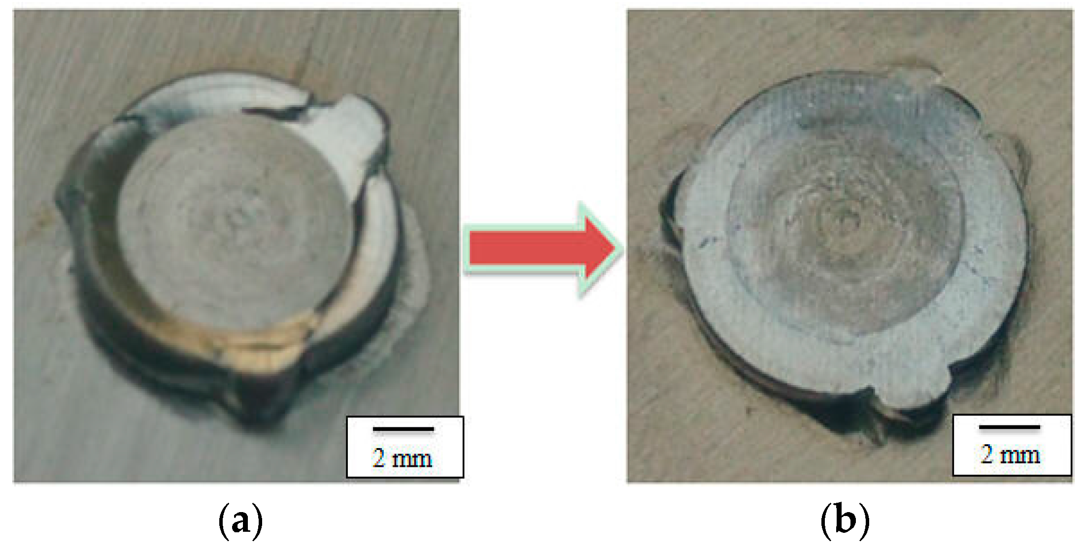
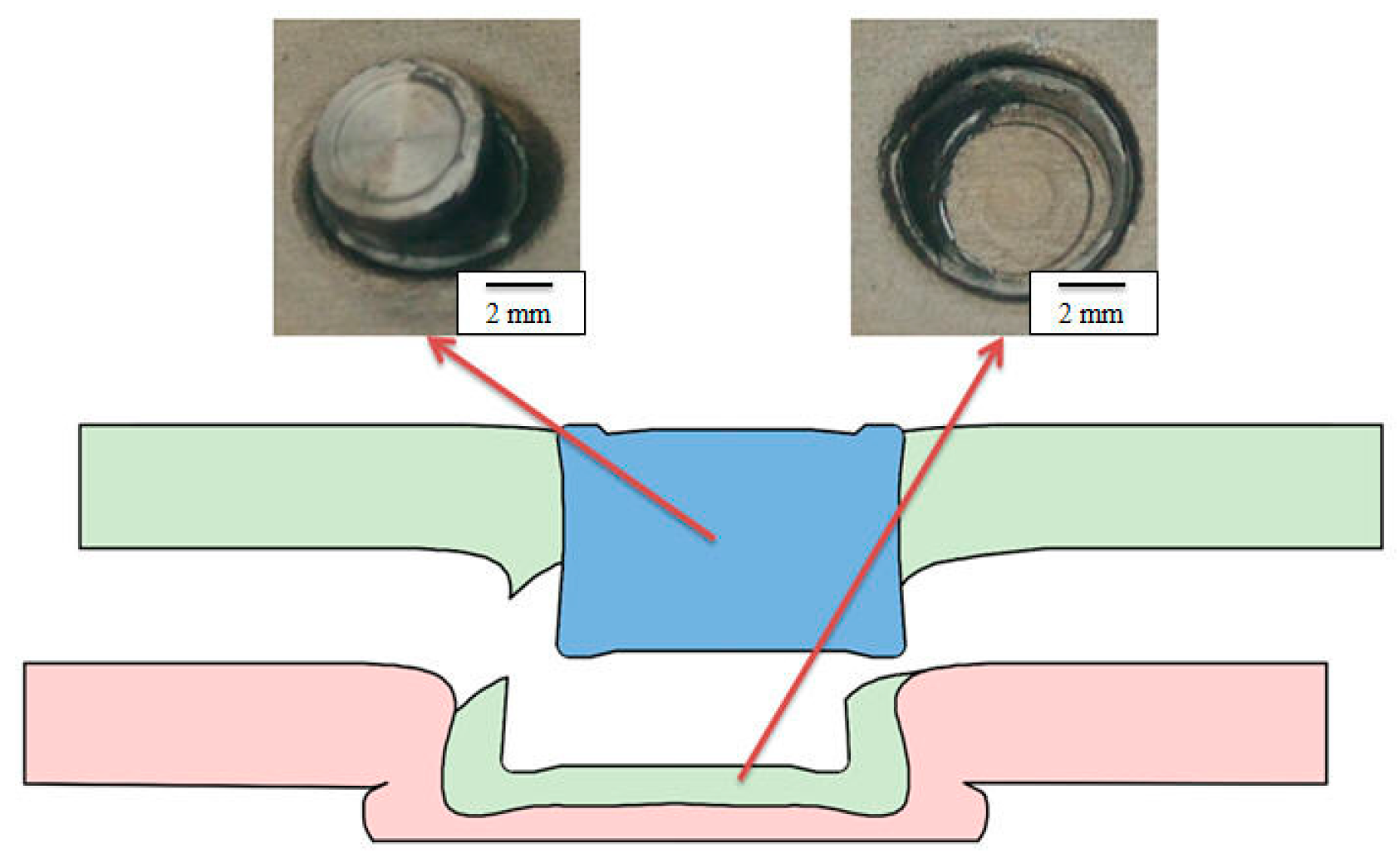
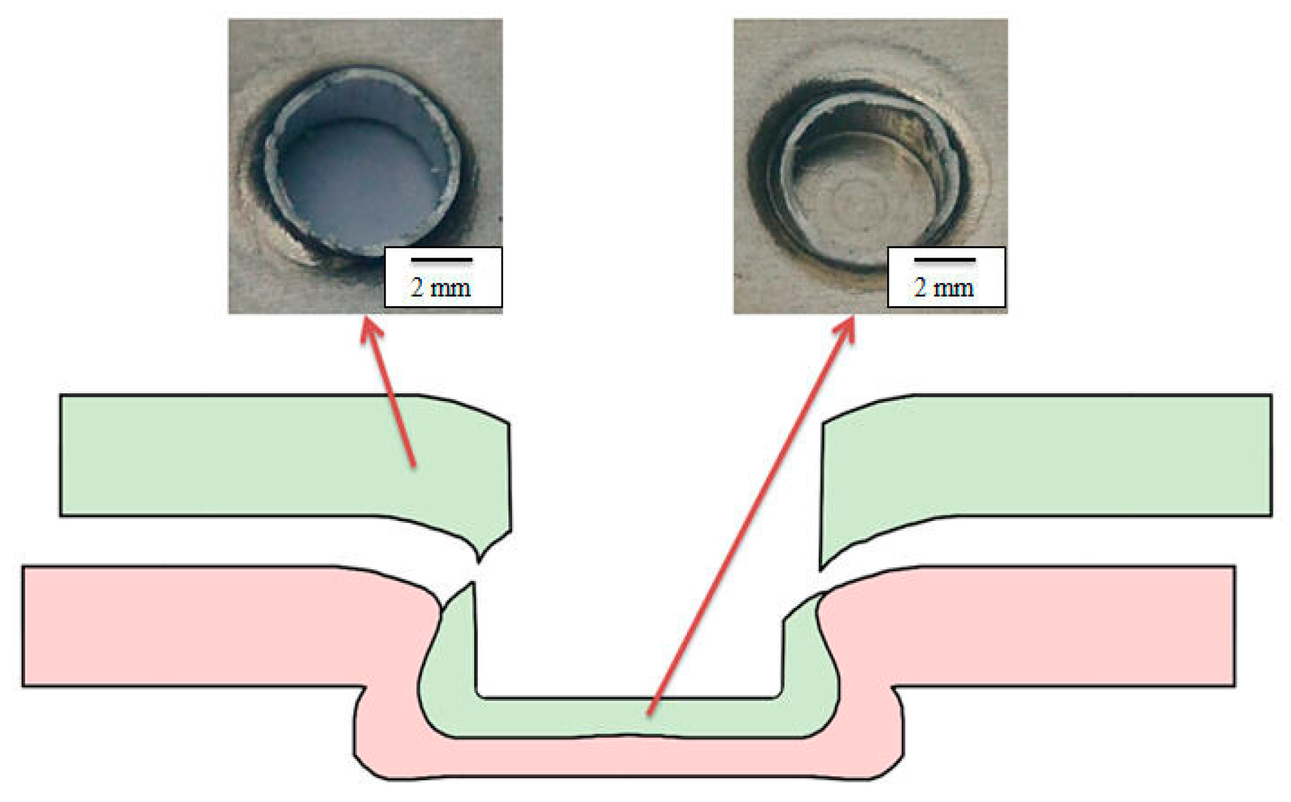
In the restoring process, the customized rivet and the joint protrusion were deformed plastically. The protrusion material was compressed to flow upward and radially. The protrusion height was reduced and the protrusion diameter was increased in the restoring process.
(2)
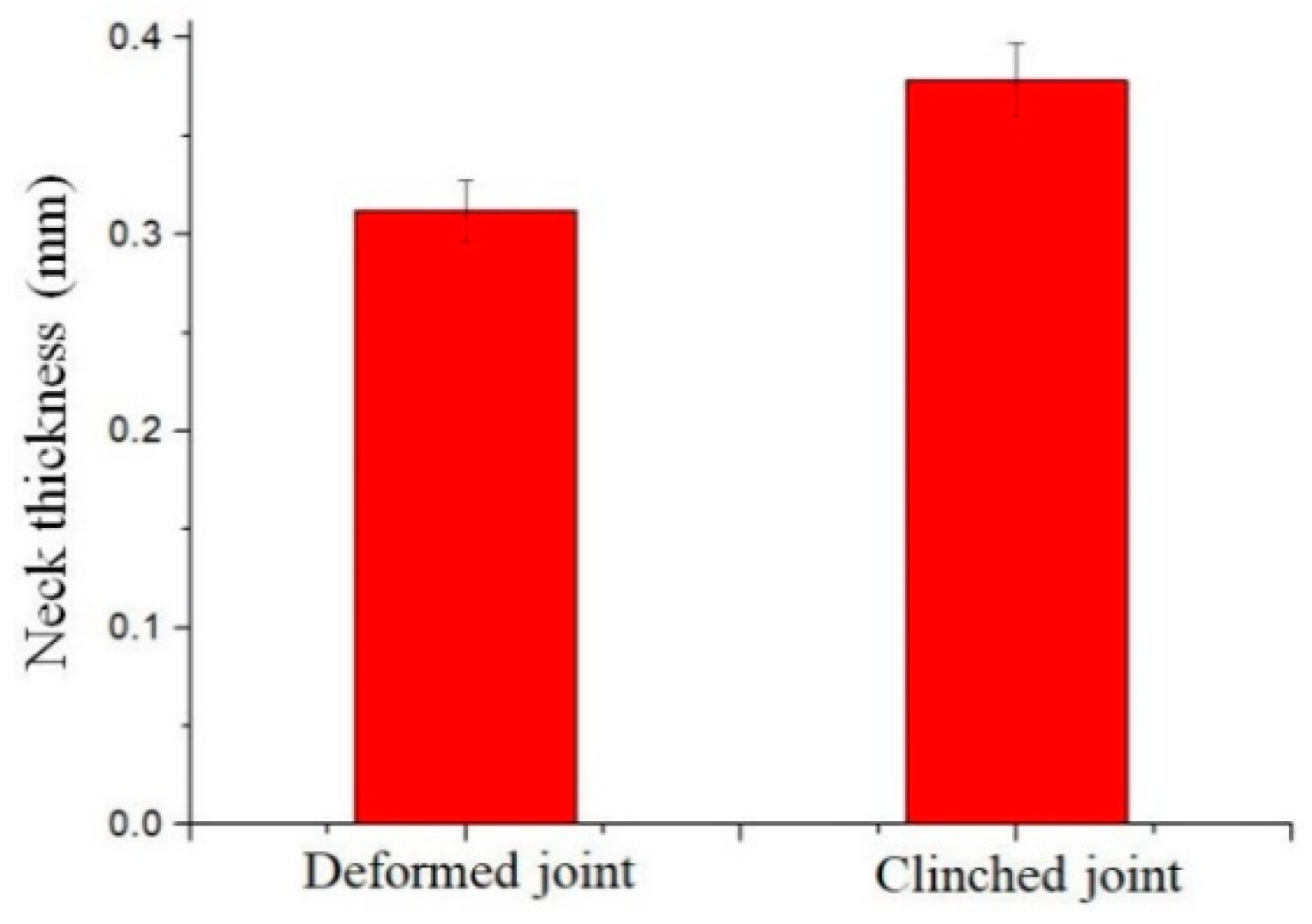
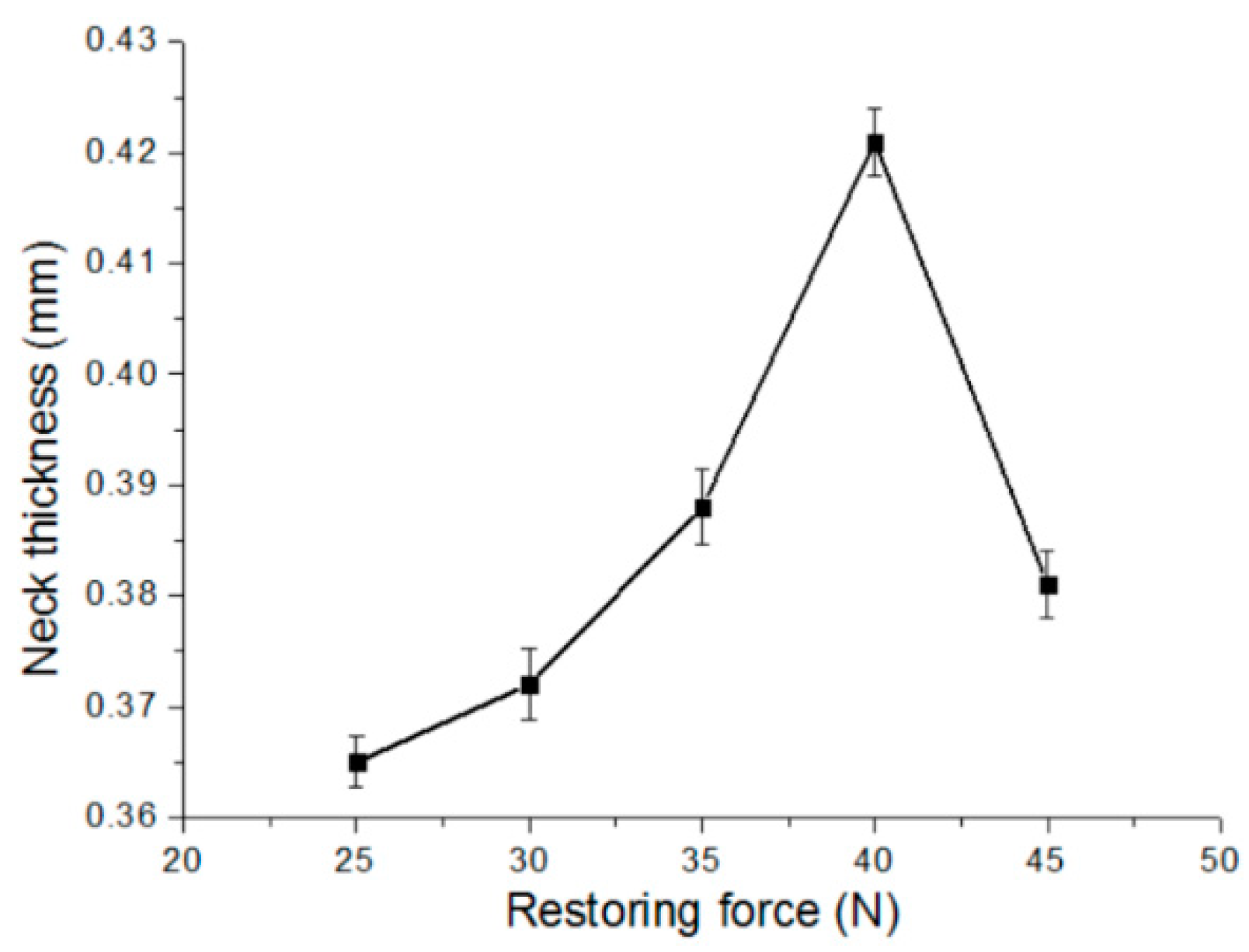
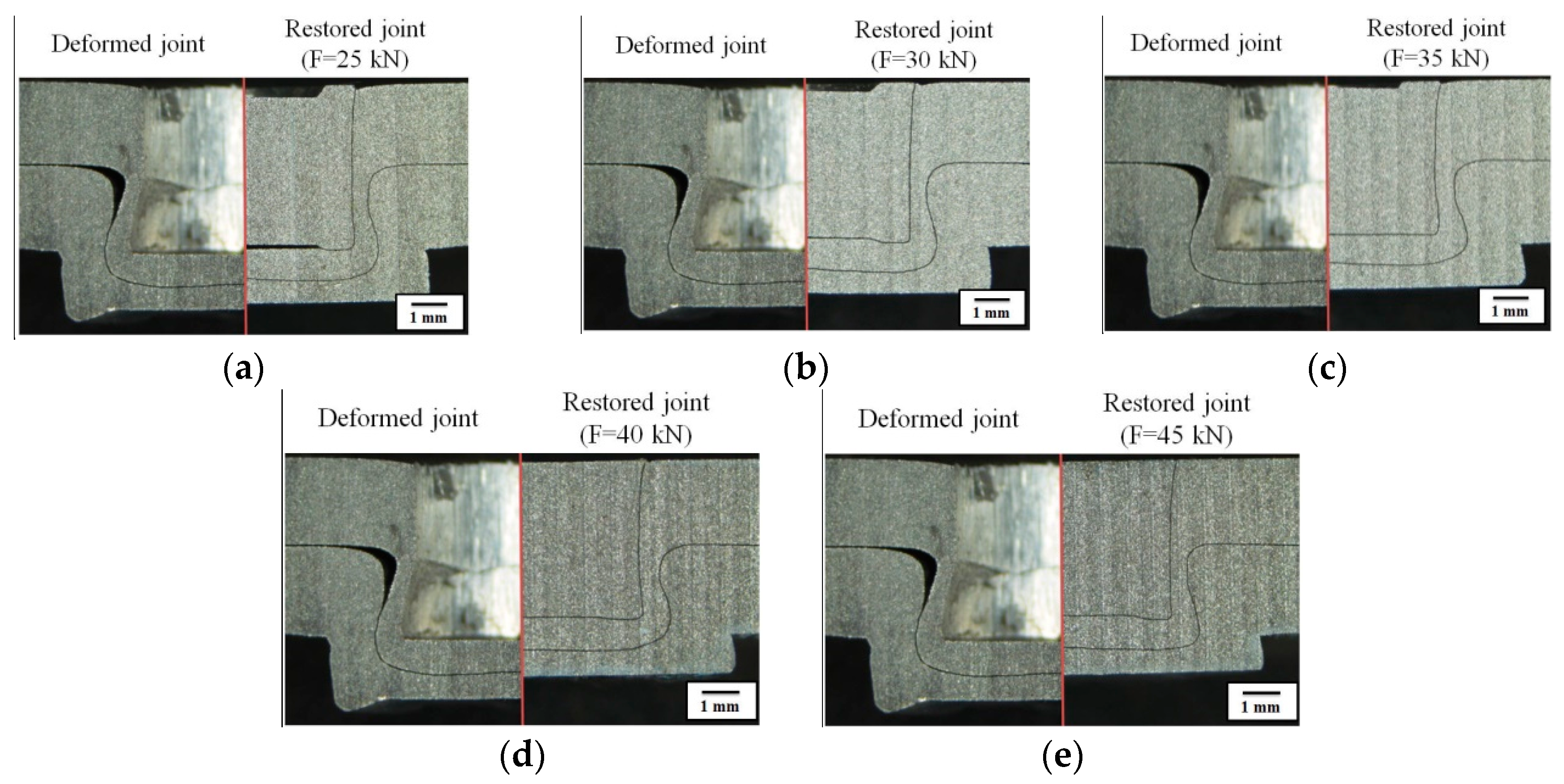
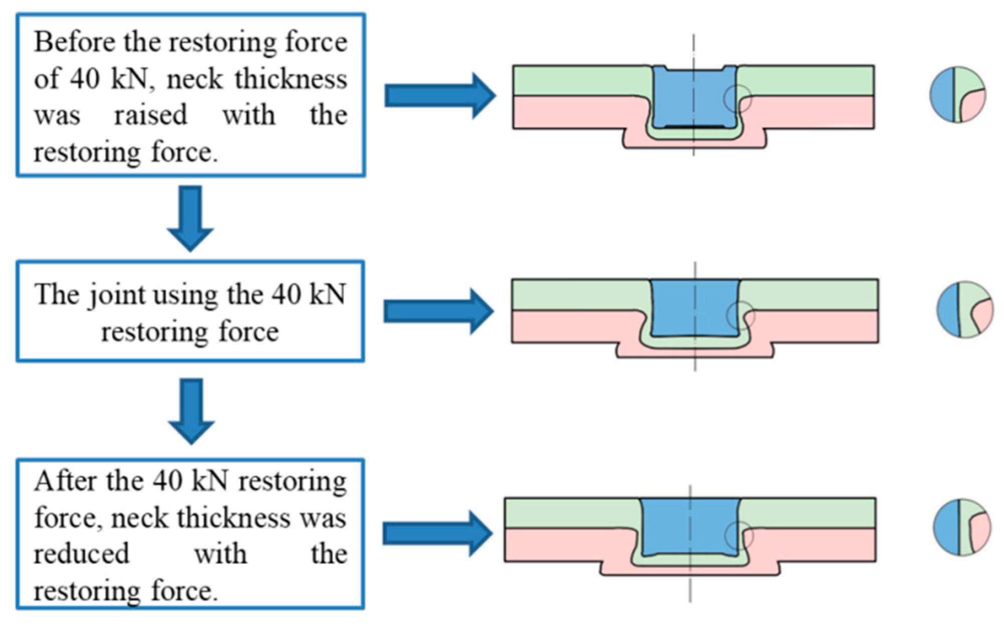
The mode of neck fracture is the main failure mode of restored joint and clinched joint, which implies the thickness of joint neck performs an indispensable role in the joint shear strength. All the deformed joints have lower thickness of neck than the restored joints. The restoring process not only can restore the deformed neck, but also can enlarge the thickness of neck.
(3)
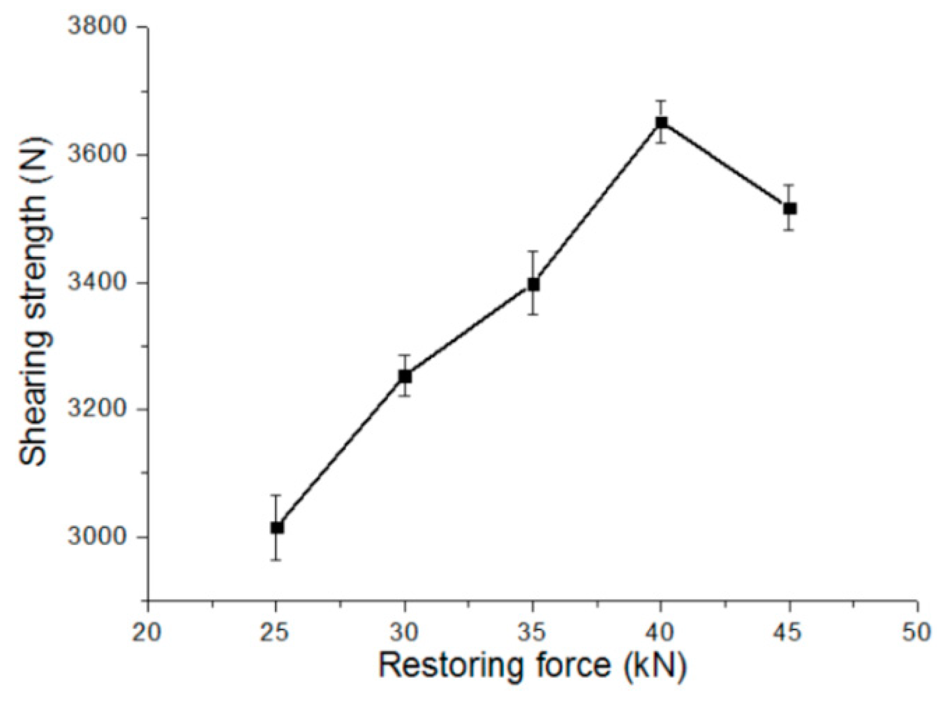
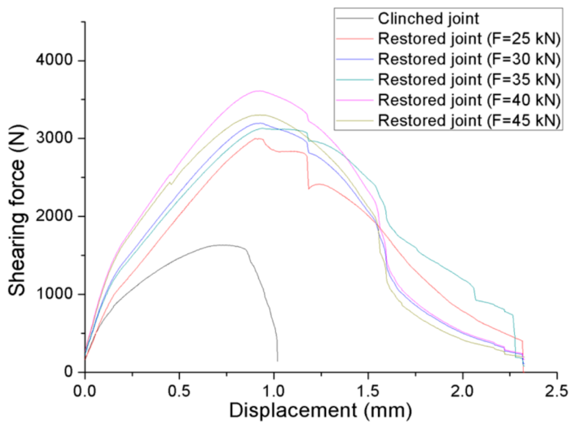
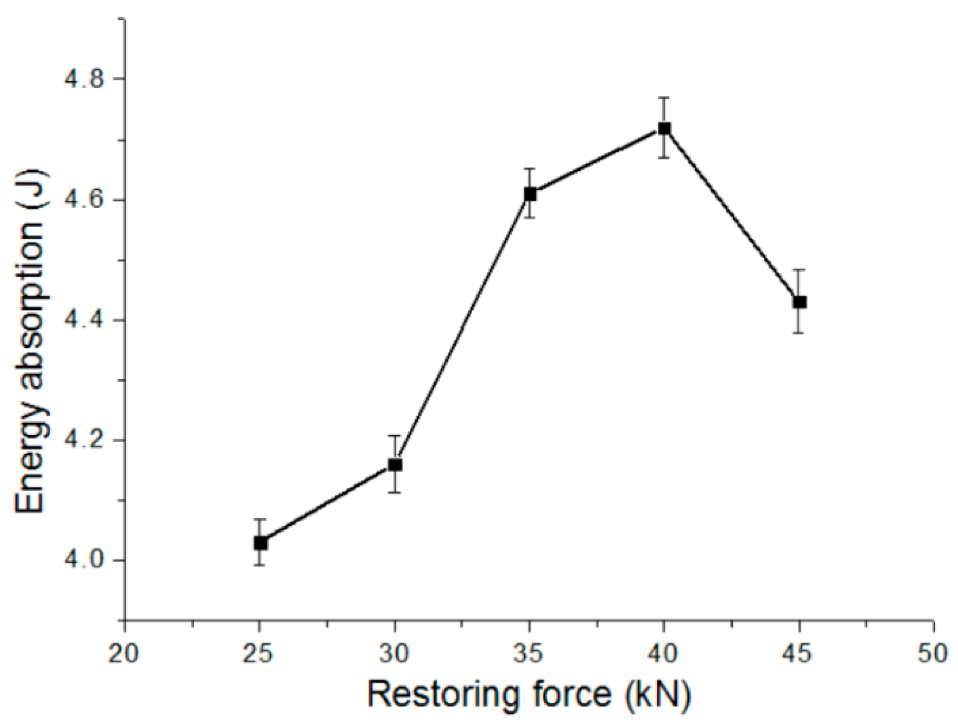
All of the clinched joints have lower absorption of energy and shear strength than the restored joints. The restored joint using the 40 kN restoring force has the highest shear strength and absorption of energy in this research.

Author Contributions

Q.P. and H.Z. conceived and designed the experiments; C.C. and H.Z. performed the experiments; H.P. and X.R. analyzed the data; C.C. and Q.P. contributed reagents/materials/analysis tools; C.C. wrote the paper. All authors have read and agreed to the published version of the manuscript.

Funding

This research was funded by the National Natural Science Foundation of China (Grant No. 51805416), the National Natural Science Foundation of China (Grant No. 51675414), Young Elite Scientists Sponsorship Program by CAST, Natural Science Basic Research Plan in Shaanxi Province of China (Program No. 2019JQ-372), Research Fund of State Key Laboratory of High Performance Complex Manufacturing (Grant No. ZZYJKT2019-01), and Huxiang High-Level Talent Gathering Project of HUNAN Province (Grant No. 2019RS1002).

Conflicts of Interest

The authors declare that they have no conflict of interest.

References

  1. Eshtayeh, M.M.; Hrairi, M. Recent and future development of the application of finite element analysis in clinching process. Int. J. Adv. Manuf. Technol. 2016, 84, 2589–2608. [Google Scholar] [CrossRef]
  2. Chen, C.; Zhao, S.D.; Cui, M.C.; Han, X.L.; Fan, S.Q. Numerical and experimental investigations of the reshaped joints with and without a rivet. Int. J. Adv. Manuf. Technol. 2017, 88, 2039–2051. [Google Scholar] [CrossRef]
  3. Calabrese, L.; Galtieri, G.; Borsellino, C.; Di Bella, G.; Proverbio, E. Durability of hybrid clinch-bonded steel aluminum joints in salt spray environment. Int. J. Adv. Manuf. Technol. 2016, 87, 3137–3147. [Google Scholar] [CrossRef]
  4. Eshtayeh, M.; Hrairi, M.; Mohiuddin, A.K.M. Multi objective optimization of clinching joints quality using Grey-based Taguchi method. Int. J. Adv. Manuf. Technol. 2016, 87, 233–249. [Google Scholar] [CrossRef]
  5. Chen, C.; Zhao, S.D.; Cui, M.C.; Han, X.L.; Fan, S.Q. Mechanical properties of the two-steps clinched joint with a clinch-rivet. J. Mater. Process. Technol. 2016, 237, 361–370. [Google Scholar] [CrossRef]
  6. Chen, C.; Zhao, S.D.; Han, X.L.; Cui, M.C.; Zhao, X.Z.; Ishida, T. Experimental investigation of the mechanical reshaping process for joining aluminum alloy sheets with different thicknesses. J. Manuf. Process. 2017, 26, 105–112. [Google Scholar] [CrossRef]
  7. Mucha, J.; Witkowski, W. The clinching joints strength analysis in the aspects of changes in the forming technology and load conditions. Thin-Walled Struct. 2014, 82, 55–66. [Google Scholar] [CrossRef]
  8. Chen, C.; Li, Y.X.; Zhai, Z.Y.; Zhao, S.D.; Zhang, P.; Huang, M.H.; Li, Y.B. Comparative investigation of three different reforming processes for clinched joint to increase joining strength. J. Manuf. Process. 2019, 45, 83–91. [Google Scholar] [CrossRef]
  9. Mucha, J.; Witkowski, W. The experimental analysis of the double joint type change effect on the joint destruction process in uniaxial shearing test. Thin-Walled Struct. 2013, 66, 39–49. [Google Scholar] [CrossRef]
  10. Chen, C.; Zhao, S.D.; Han, X.L.; Cui, M.C.; Fan, S.Q. Investigation of mechanical behavior of the reshaped joints realized with different reshaping forces. Thin-Walled Struct. 2016, 107, 266–273. [Google Scholar] [CrossRef]
  11. Eshtayeh, M.; Hrairi, M.; Mohiuddin, A.K.M. Clinching process for joining dissimilar materials: State of the art. Int. J. Adv. Manuf. Technol. 2016, 82, 179–195. [Google Scholar] [CrossRef]
  12. Chen, C.; Fan, S.Q.; Han, X.L.; Zhao, S.D.; Cui, M.C.; Ishida, T. Experimental study on the height-reduced joints to increase the cross-tensile strength. Int. J. Adv. Manuf. Technol. 2017, 91, 2655–2662. [Google Scholar] [CrossRef]
  13. Chen, C.; Zhao, S.D.; Cui, M.C.; Han, X.L.; Zhao, X.Z.; Ishida, T. Effects of geometrical parameters on the strength and energy absorption of the height-reduced joint. Int. J. Adv. Manuf. Technol. 2017, 90, 3533–3541. [Google Scholar] [CrossRef]
  14. Wen, T.; Huang, Q.; Liu, Q.; Ou, W.X.; Zhang, S. Joining different metallic sheets without protrusion by flat hole clinching process. Int. J. Adv. Manuf. Technol. 2014, 85, 217–225. [Google Scholar] [CrossRef]
  15. Chen, C.; Zhao, S.D.; Cui, M.C.; Han, X.L.; Fan, S.Q.; Ishida, T. An experimental study on the compressing process for joining Al6061 sheets. Thin-Walled Struct. 2016, 108, 56–63. [Google Scholar] [CrossRef]
  16. Pinger, T.; Rückriem, E.-M. Investigation on the corrosion and mechanical behavior of thin film batch galvanized thick plate components in clinch joints. Int. J. Adv. Manuf. Technol. 2016, 86, 29–36. [Google Scholar] [CrossRef]
  17. Chen, C.; Zhao, S.D.; Cui, M.C.; Han, X.L.; Fan, S.Q.; Zhao, X.Z. Comparative investigation of auxiliary processes for increasing the strength of clinched joints. Proc. Inst. Mech. Eng. Part E J. Process. Mech. Eng. 2018, 232, 165–172. [Google Scholar] [CrossRef]
  18. Neugebauer, R.; Todtermuschke, M.; Mauermann, F.; Riedel, F. Overview on the state of development and the application potential of dieless mechanical joining processes. Arch. Civ. Mech. Eng. 2008, 4, 51–60. [Google Scholar] [CrossRef]
  19. Mucha, J.; Kašcák, L.; Spišák, E. Joining the car-body sheets using clinching process with various thickness and mechanical property arrangements. Arch. Civ. Mech. Eng. 2011, 11, 135–148. [Google Scholar] [CrossRef]
  20. Chen, C.; Zhao, S.D.; Han, X.L.; Cui, M.C.; Fan, S.Q. Investigation of the height-reducing method for clinched joint with AL5052 and AL6061. Int. J. Adv. Manuf. Technol. 2017, 89, 2269–2276. [Google Scholar] [CrossRef]
  21. Oudjene, M.; Ben-Ayed, L.; Delamézière, A.; Batoz, J.-L. Shape optimization of clinching tools using the response surface methodology with Moving Least-Square approximation. J. Mater. Process. Technol. 2009, 209, 289–296. [Google Scholar] [CrossRef]
  22. Lee, C.J.; Kim, J.Y.; Lee, S.K.; Ko, D.C.; Kim, B.M. Design of mechanical clinching tools for joining of aluminium alloy sheets. Mater. Des. 2010, 31, 1854–1861. [Google Scholar] [CrossRef]
  23. Lambiase, F.; Di Ilio, A. An experimental study on clinched joints realized with different dies. Thin-Walled Struct. 2014, 85, 71–80. [Google Scholar] [CrossRef]
  24. Mucha, J. The analysis of lock forming mechanism in the clinching joint. Mater. Des. 2011, 32, 4943–4954. [Google Scholar] [CrossRef]
  25. Lambiase, F. Influence of process parameters in mechanical clinching with extensible dies. Int. J. Adv. Manuf. Technol. 2013, 66, 2123–2131. [Google Scholar] [CrossRef]
  26. Oudjene, M.; Ben-Ayed, L. On the parametrical study of clinch joining of metallic sheets using the Taguchi method. Eng. Struct. 2008, 30, 1782–1788. [Google Scholar] [CrossRef]
  27. He, X.C.; Liu, F.L.; Xing, B.Y.; Yang, H.Y.; Wang, Y.Q.; Deng, C.J.; Gu, F.S.; Ball, A. Numerical and experimental investigations of extensible die clinching. Int. J. Adv. Manuf. Technol. 2014, 74, 1229–1236. [Google Scholar] [CrossRef]
  28. Lambiase, F.; Durante, M.; Di Ilio, A. Fast joining of aluminum sheets with Glass Fiber Reinforced Polymer (GFRP) by mechanical clinching. J. Mater. Process. Technol. 2016, 236, 241–251. [Google Scholar] [CrossRef]
  29. Lambiase, F.; Ko, D.-C. Feasibility of mechanical clinching for joining aluminum AA6082-T6 and Carbon Fiber Reinforced Polymer sheets. Mater. Des. 2016, 107, 341–352. [Google Scholar] [CrossRef]
  30. Lambiase, F.; Di Ilio, A. Mechanical clinching of metal–polymer joints. J. Mater. Process. Technol. 2015, 215, 12–19. [Google Scholar] [CrossRef]
  31. Lambiase, F. Joinability of different thermoplastic polymers with aluminium AA6082 sheets by mechanical clinching. Int. J. Adv. Manuf. Technol. 2015, 80, 1995–2006. [Google Scholar] [CrossRef]
  32. Lambiase, F. Mechanical behaviour of polymer–metal hybrid joints produced by clinching using different tools. Mater. Des. 2015, 87, 606–618. [Google Scholar] [CrossRef]
  33. Jiang, T.; Liu, Z.X.; Wang, P.C. Effect of aluminum pre-straining on strength of clinched galvanized SAE1004 steel-to-AA6111-T4 aluminum. J. Mater. Process. Technol. 2015, 215, 193–204. [Google Scholar] [CrossRef]
  34. Jiang, T.; Liu, Z.X.; Wang, P.C. Quality inspection of clinched joints of steel and aluminum. Int. J. Adv. Manuf. Technol. 2015, 76, 1393–1402. [Google Scholar] [CrossRef]
  35. Abe, Y.; Mori, K.; Kato, T. Joining of high strength steel and aluminium alloy sheets by mechanical clinching with dies for control of metal flow. J. Mater. Process. Technol. 2012, 212, 884–889. [Google Scholar] [CrossRef]
  36. Lee, C.J.; Lee, J.M.; Ryu, H.Y.; Lee, H.Y.; Lee, K.H.; Kim, B.M.; Ko, D.C. Design of hole-clinching process for joining of dissimilar materials—Al6061-T4 alloy with DP780 steel, hot-pressed 22MnB5 steel, and carbon fiber reinforced plastic. J. Mater. Process. Technol. 2014, 214, 2169–2178. [Google Scholar] [CrossRef]
  37. Xing, B.Y.; He, X.C.; Wang, Y.Q.; Yang, H.Y.; Deng, C.J. Study of mechanical properties for copper alloy H62 sheets joined by self-piercing riveting and clinching. J. Mater. Process. Technol. 2015, 216, 28–36. [Google Scholar] [CrossRef]
  38. He, X.C.; Zhang, Y.; Xing, B.Y.; Gu, F.S.; Ball, A. Mechanical properties of extensible die clinched joints in titanium sheet materials. Mater. Des. 2015, 71, 26–35. [Google Scholar] [CrossRef]
  39. Zhao, S.D.; Xu, F.; Guo, J.H.; Han, X.L. Experimental and numerical research for the failure behavior of the clinched joint using modified Rousselier model. J. Mater. Process. Technol. 2014, 214, 2134–2145. [Google Scholar] [CrossRef]
  40. Xu, F.; Zhao, S.D.; Han, X.L. Use of a modified Gurson model for the failure behaviour of the clinched joint on Al6061 sheet. Fatigue Fract. Eng. Mater. Struct. 2014, 37, 335–348. [Google Scholar] [CrossRef]
  41. Lambiase, F.; Di Ilio, A. Damage analysis in mechanical clinching: Experimental and numerical study. J. Mater. Process. Technol. 2016, 230, 109–120. [Google Scholar] [CrossRef]
Figure 1. The schematic drawings of the deforming process of the clinched joint bearing a shear force on the lower sheet and upper sheet: (a) The initial state, (b) The intermediate state, and (c) The final state.
Metals 10 00097 g001
Figure 2. The Schematic drawings of the process of restoring deformed joint: (a) the final shape of the clinched joint, (b) the initial state of the restoring process, and (c) the final state the restoring process.
Metals 10 00097 g002
Figure 3. Extensible dies.
Metals 10 00097 g003
Figure 4. The Schematic drawings of the specimen employed for deforming process. (unit: mm)
Metals 10 00097 g004
Figure 5. Restoring tools and rivet: (a) Restoring tools and (b) Customized rivet.
Metals 10 00097 g005
Figure 6. Shear specimen.
Metals 10 00097 g006
Figure 7. The cross-sectional profiles of the joints compressed with different restoring forces: (a) F = 25 kN; (b) F = 30 kN; (c) F = 35 kN; (d) F = 40 kN; and (e) F = 45 kN. (The deformed joint is the left cross-sectional profile of each figure, and the restored joint is the right cross-sectional profile of each figure).
Metals 10 00097 g007
Figure 8. Protrusion of the joint with the extensible dies: (a) Before being compressed by the flat dies and (b) After being compressed by the flat die.
Metals 10 00097 g008
Figure 9. The failure mode of neck fracture of clinched joint (The top is the actual joint failure picture, and the bottom is the schematic drawing of the joint failure).
Metals 10 00097 g009
Figure 10. The failure mode of neck fracture of restored joint. (The top is the actual joint failure picture and the bottom is the schematic drawing of the joint failure).
Metals 10 00097 g010
Figure 11. The average neck thicknesses of the deformed joint and clinched joint.
Metals 10 00097 g011
Figure 12. The effect of a series of restoring forces employed on the restored joint on neck thicknesses of joint.
Metals 10 00097 g012
Figure 13. Schematic of the neck thickness evolution.
Metals 10 00097 g013
Figure 14. The average shear strengths of the restored joints using a series of restoring forces.
Metals 10 00097 g014
Figure 15. Shear force-displacement curves of the joints using a series of restoring forces after restoring processes.
Metals 10 00097 g015
Figure 16. The effect of a series of restoring forces employed on the restored joint on energy absorption.
Metals 10 00097 g016

