Article

The Mechanism for HAZ Liquation of Nickel-Based Alloy 617B During Gas Tungsten Arc Welding

1
Department of Mechanical Engineering, Tsinghua University, Beijing 10084, China
2
Key Laboratory for Advanced Materials Processing Technology, Ministry of Education, Beijing 100084, China
3
Tianjin Research Institute for Advanced Equipment, Tsinghua University, Tianjin 300300, China
4
Collaborative Innovation Center of Advanced Nuclear Energy Technology, Tsinghua University, Beijing 10084, China
5
State Key Laboratory of Tribology, Tsinghua University, Beijing 10084, China
*
Authors to whom correspondence should be addressed.
Metals 2020, 10(1), 94; https://doi.org/10.3390/met10010094
Submission received: 26 November 2019 / Revised: 26 December 2019 / Accepted: 2 January 2020 / Published: 6 January 2020
(This article belongs to the Special Issue Microstructure and Properties of Metallic Heat-Affected Zones)

Abstract

:
The mechanism for HAZ (heat-affected zone) liquation of alloy 617B during gas tungsten arc welding (GTAW) was investigated. Welding thermal simulation work was conducted to investigate the effects of thermal parameters (peak temperature, holding time, and thermal cycle numbers) on M23C6 carbides’ evolutionary behavior in nickel-based alloy 617B. OM (optical microscopy), SEM (scanning electron microscopy), TEM (transmission electron microscopy), and SIMS (secondary ion mass spectrometry) were employed to characterize HAZ carbides. It was found that the constitutional liquation of M23C6 carbides is responsible for HAZ liquation in alloy 617B. Rapid heating meant that solute atoms released from partially dissolved M23C6 carbides did not have enough time to sufficiently diffuse into the matrix, resulting in eutectic reaction M23C6 + γ → liquid in the temperature range from 1250 °C to 1300 °C. In the following cooling process, the liquid phase transformed into γ and M23C6 (or M6C) carbides simultaneously, creating a eutectic microstructure. Subsequent thermal cycles with peak temperature 1100 °C and proper holding time brought about a tempering effect to precipitate fine M23C6 carbides from the Cr supersaturated zone around the eutectic microstructure. Boron was found to be enriched in carbides and was expected to promote HAZ liquation by two mechanisms. No cracking caused by HAZ liquation has been found, indicating that GTAW is a suitable method for joining alloy 617B.

1. Introduction

Nickel-based alloy 617B, a boron-modified version of the commercial alloy 617, has been widely used in fossil fuel power plants due to its excellent creep and oxidation resistance [1,2]. Welding is a common technique to join nickel-based alloys and other metals such as steels. For nickel-based alloys, welding provides thermal cycles far away from equilibrium, presenting some new metallurgical phenomena such as liquation cracking [3,4,5], solidification cracking [6,7,8], and so on. These phenomena lead to a decline in joint performance [9,10]. Much work has been conducted by other researchers to clarify the reasons for these phenomena and to eliminate or reduce the cracks resulting from welding.
In terms of liquation cracking in nickel-based alloys, it tends to occur in welding HAZ, where only solid-state phase transformation is supposed to take place. Liquation cracking forms in the presence of liquation and thermal tensile stress. During the heating process, some liquid will form, wetting the grain boundaries. If the stress applied to the weld joint exceeds the strength limit of the wet grain boundaries, cracks will form along these grain boundaries. There are two main mechanisms for HAZ liquation, one of which is connected to minor elements, such as B, P, and S. These minor elements tend to segregate at grain boundaries, lowering the melting point [11,12]. Although the temperature is lower than solidus during heating, some liquid will form at the grain boundaries. Nowadays, the amount of P+S can be as low as 100 ppm (0.01 wt %) by using a special double-melting technique, and at this level, the role of P and S in liquation cracking can be negligible. However, the contribution of boron to HAZ liquation cannot be ignored in some alloys, such as alloy 617B and 718 plus, because a certain amount of boron has been introduced in these alloys for the purpose of improving creep resistance [13,14]. Except for lowering the melt point of grain boundaries, boron has an ability to promote the liquid phase to spread the grain boundary, thereby promoting the development of HAZ liquation [15,16]. The other mechanism for HAZ liquation is constitutional liquation, resulting from eutectic reactions between some large precipitates and the matrix [17]. In nickel-based alloys, the precipitates leading to constitutional liquation can be carbides or intermetallic compounds such as MC [18,19,20], M6C [19], or Laves phase [21]. During the rapid heating provided by welding, there is not enough time for solute atoms released from dissolving precipitates to diffuse into the matrix homogeneously, causing subsequent eutectic reactions between the incompletely dissolved precipitates and the saturated matrix.
Researchers have reported that HAZ liquation occurs in the welding of alloy 617. Wen [3] reported the behavior of grain boundary liquation cracking in fiber laser welding of alloy 617 and found that the degree of liquation cracking decreased when the heating input and preheating temperature increased. Phuraya [22] used a high-temperature confocal laser scanning microscopy to investigate the liquation process of alloy 617 by in situ observation. Meanwhile, Xu [23] reported that some lamellar structures occurred near the fusion line of alloy 617B welded joint and found that the peak temperature played a key role in the formation of these lamellar structures. Fink and Zinke [24] found that liquation cracking occurred predominantly at or near the fusion line in the welded joint of alloy 617, and interdendritic enrichment of Mo formed at the crack tip. These studies suggest that HAZ liquation might occur in the welded joint of alloy 617B. Studies need to be conducted to verify HAZ liquation and to reveal the liquation mechanism of 617B during welding. In the present work, thermal simulation was applied to reveal the microstructure evolution of HAZ. The influence of peak temperature and the number of thermal cycles on carbides’ behavior were performed, and the distribution and effect of boron were also discussed.

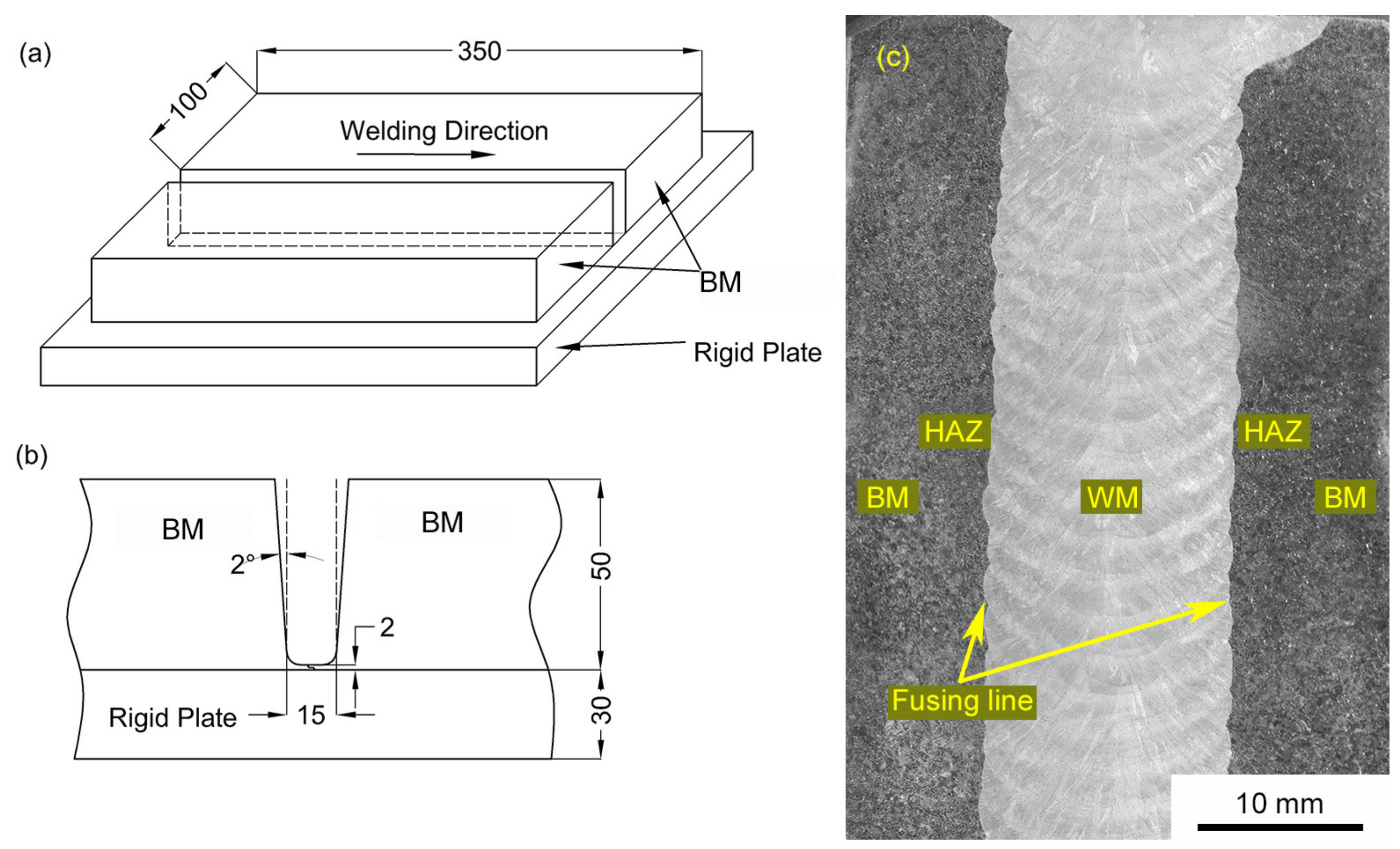
2. Materials and Methods

Alloy 617B, used in the present work, was provided by ThyssenKrupp VDM® (Plettenberger Straße 2, Werdohl, Germany), and was produced by vacuum induction melting (VIM), electroslag remelting (ESR), hot-rolling, and solution annealing at 1150 for 2 h. The thermal conductivity coefficients at room temperature and 1200 °C are 11.7 W/mK and 32.3 W/mK, and the melting range of this alloy is about 1330° C to 1380 °C [13]. Two workpieces of alloy 617B with a thickness of 50 mm were joined by the GTAW multi-layer technique. The set-up structure and groove are shown in Figure 1a,b. A filler metal (ERNiCrCoMo-1) was selected to obtain a matched creep rupture strength with the 617B base metal (BM). The chemical compositions of the as-received 617B and the filler metal are listed in Table 1. The detailed welding parameters are shown in Table 2. A transverse section, containing BM, HAZ, and WM (weld metal), as shown in Figure 1c, was cut from the welded joint by electrodischarge machining for microstructural investigation.
As the HAZ in multi-pass welded joint is very narrow and inhomogeneous, it is difficult to investigate the effects of welding thermal cycles on the HAZ microstructure quantitatively. To solve this problem, thermal simulations were carried out on a DIL 805A dilatometer to duplicate the microstructure in HAZ. Specimens with a dimension of 10 × 5 × 5 (in mm) were employed in these experiments. Considering the characteristic of multi-layer welding process, HAZ would experience more than one thermal cycle. The HAZ microstructure produced by the previous weld thermal cycle might be altered by the subsequent ones. Therefore, two types of thermal cycles were applied in thermal simulation work, as shown in Figure 2. The thermal simulations with one thermal cycle, as shown in Figure 2a, were carried out to investigate the primary HAZ microstructure produced by the first thermal cycle. These specimens were heated to a range of peak temperatures (Tp1 = 1200 °C, 1250 °C, and 1300 °C) at a rate of 100 °C /s, held at the peak temperature for tp1 = 0.5 s and then cooled down to room temperature at a rate of 200 °C /s. To investigate the effect of the subsequent thermal cycle on HAZ microstructures produced by the previous one, one more thermal cycle was added, as shown in Figure 2b. The peak temperature Tp2 of the second thermal cycle was set as 1100 °C and the holding times tp2 were set as 1 s, 5 s, 10 s, and 20 s, respectively. The argon atmosphere was maintained in the thermal simulation to protect the specimens from oxidation. Two samples were processed and the metallography observed for each condition. It should be noted that, due to equipment limitations, the heating rate of 100 °C /s applied in this research is much lower than that in the actual HAZ, which could reach more than 1000 °C /s during GTAW welding [25]. However, the heating rate applied in our research is feasible for revealing the microstructural evolution in actual HAZ, because the same microstructure in actual HAZ has been obtained in thermal simulation samples. In the section No. 4 in this paper, the influence of heating rate on the microstructural evolution of HAZ will be discussed in detail.
Microstructural analysis of welded joint and simulated HAZ specimens was carried out by OM, SEM, and TEM. EDX (energy-dispersive X-ray spectrometry), used in SEM and TEM systems, was employed for chemical composition measurement. The TEM specimens were prepared by FIB (focused ion beam). SAED (selected area electron diffraction) was conducted to identify the phase type of interest. SIMS was applied to analyze the boron distribution in the alloy. These samples were mechanically polished, then etched with Kalling’s reagent (100 mL hydrochloric acid +100 mL alcohol +5 g copper chloride) for 150 s to reveal the microstructure for SEM and SIMS analysis.

3. Results

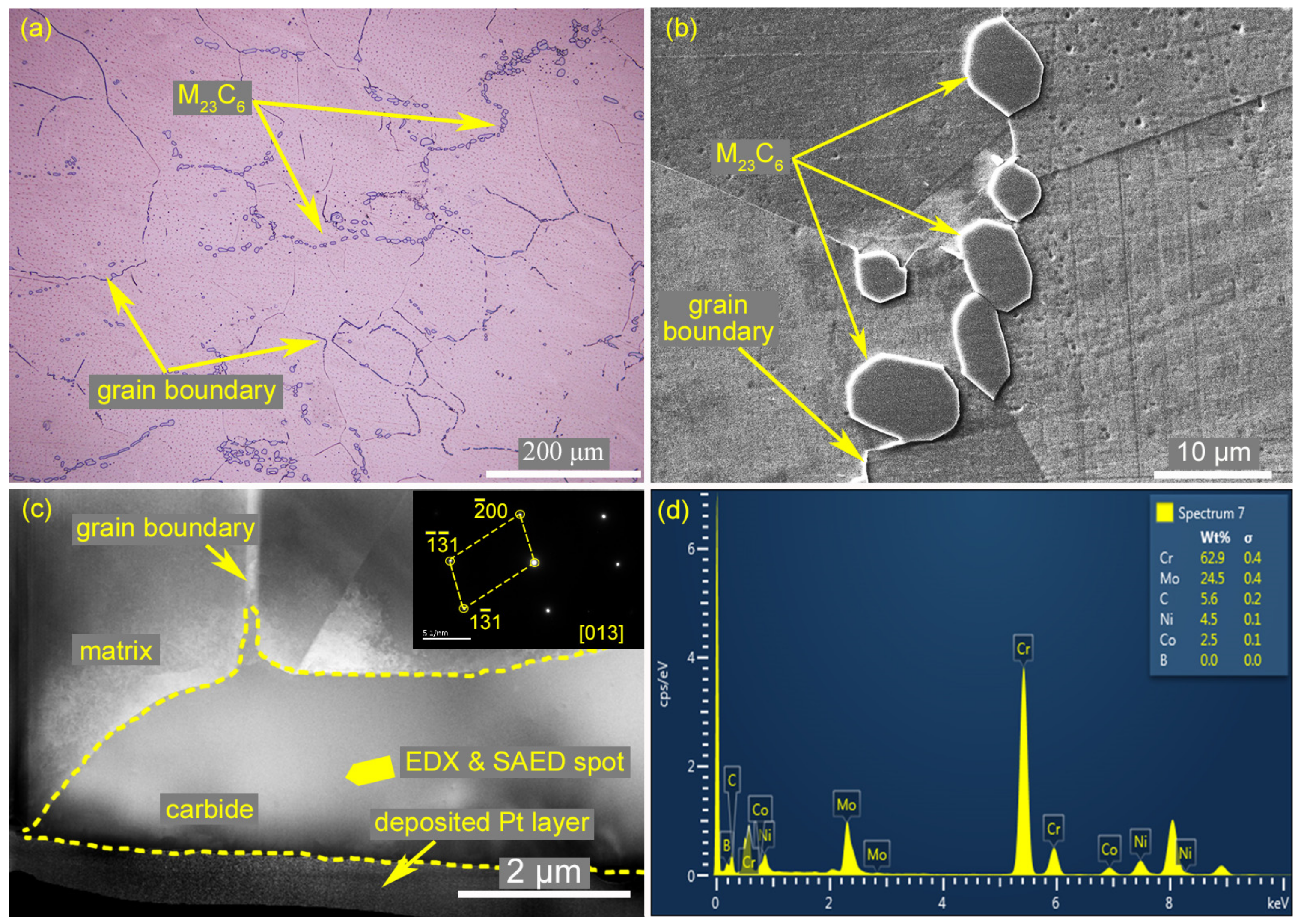
3.1. Microstructures of the Welded Joint

The microstructure of BM under as-received condition is shown in Figure 3. This microstructure features an austenitic matrix and many large-sized particles, as shown in Figure 3a,b. The austenitic grain size in the matrix is within the range from 30 to 300 μm. In Figure 3b, globular particles of about 3–10 μm are distributed along the grain boundaries discontinuously. Figure 3c shows the morphology and SAED pattern of these particles obtained by TEM. SAED pattern analysis suggests that these particles have an FCC structure with a lattice constant of 10.69 Å. The EDX results (Figure 3d) indicate that these particles are rich in Cr, Mo, and C. Both structural and chemical analyses suggest that these particles are M23C6-type carbides, which is consistent with Tytko’s findings [26].
The microstructure of the welded joint from HAZ to WM is shown in Figure 4a. No obvious grain growth was found in HAZ after welding. However, particles with different morphologies were observed near the fusion line, as shown in Figure 4b. Magnified views of these particles in HAZ are shown in Figure 4c–e. It is obvious that the particle morphologies are highly related to their distance to the fusion line, namely the different peak temperatures experienced during welding. In Figure 4b, the carbide in the red rectangular, which is far away from the fusion line, maintains a similar size and shape to those under as-received condition. Closer to the fusion line, a new kind of microstructure with a network shape surrounded by some fine precipitates is observed, as shown in Figure 4d,e.
Elemental mapping analysis by EDX was employed and the main elements (Cr and Mo) in these particles are shown in Figure 4f–h. It is revealed that the particle in Figure 4c is rich in Cr, similar to that of M23C6 carbides in Figure 3d. However, the element maps in Figure 4g and h indicate that both Cr and Mo are enriched in these microstructures, implying the presence of a new microstructure composed of multiple phases. The detailed chemical compositions of the Cr-rich phase and Mo-rich phase, marked by A and B are listed in Table 3. In addition, a Cr-rich region surrounding these microstructures can be seen in Figure 4h, different from the carbides in Figure 4f. According to the above results, it seems that the M23C6 carbides evolve in different manners due to the different peak temperatures that they experience. To clarify the effects of welding thermal cycles on M23C6 carbides’ evolutionary behavior, thermal simulations with a range of peak temperatures and different numbers of cycles were conducted.

3.2. Thermal Simulation with One Thermal Cycle

Different distances to the fusion line mean different peak temperatures during the welding process. To clarify the effect of the peak temperatures on carbides’ evolutionary behavior, three typical peak temperatures (1200 °C, 1250 °C, and 1300 °C) were selected, with the thermal curves shown in Figure 2a. Particles with different morphologies after thermal simulations were observed by SEM, as shown in Figure 5.
There is no discernible change in the simulated specimens with Tp1 = 1200 °C and 1250 °C compared with the carbides under as-received condition, as shown in Figure 5a,b. As Tp1 reaches 1300 °C, the globular M23C6 is replaced by network-shaped microstructures, as shown in Figure 5c. A magnified image of network-shaped microstructure is shown in Figure 5d; its morphology is similar to that presented in Figure 4e. The thermal simulation results indicate that the temperature at which the globular M23C6 transforms into network-shaped microstructures is in the range from 1250 °C to 1300 °C. However, it should be noted that there are differences between the thermal simulated microstructure and that of the real welded joint: in the simulated specimen no fine precipitates are observed surrounding the network-shaped microstructure, while fine precipitates are present in the real welded joint (Figure 4e). In addition, a sunken zone caused by etching was observed surrounding the network-shaped microstructures, as shown in Figure 5c,d, indicating that the chemical composition was altered in this region.

3.3. Thermal Simulation with Two Thermal Cycles

As mentioned above, no fine precipitate has been found around the network-shaped microstructure in the simulated specimens experiencing only one thermal cycle. The presence of fine precipitates might be related to the multiple thermal cycles that the real HAZ is subjected to, which means that thermal cycles of the subsequent layers might temper the HAZ formed by previous ones. To clarify the effect of subsequent thermal cycles on the presence of fine precipitates, thermal simulations with two thermal cycles (as shown in Figure 2b) were conducted and the typical microstructures produced by the thermal simulations are shown in Figure 6.
It is evident that fine precipitates form after undergoing two thermal cycles when the holding time of the second cycle tp2 is 5 s or longer, as shown in Figure 6b–d. When tp2 is 1 s, there is no fine precipitate observed (Figure 6a), which might be attributed to the insufficient holding time for the precipitates to form. In addition, by comparing Figure 6b,c, it is obvious that the fine precipitates of tp2 = 10 s are much coarser than those of tp2 = 5 s; this might be ascribed to the longer time for the forming atoms to diffuse to the precipitates.

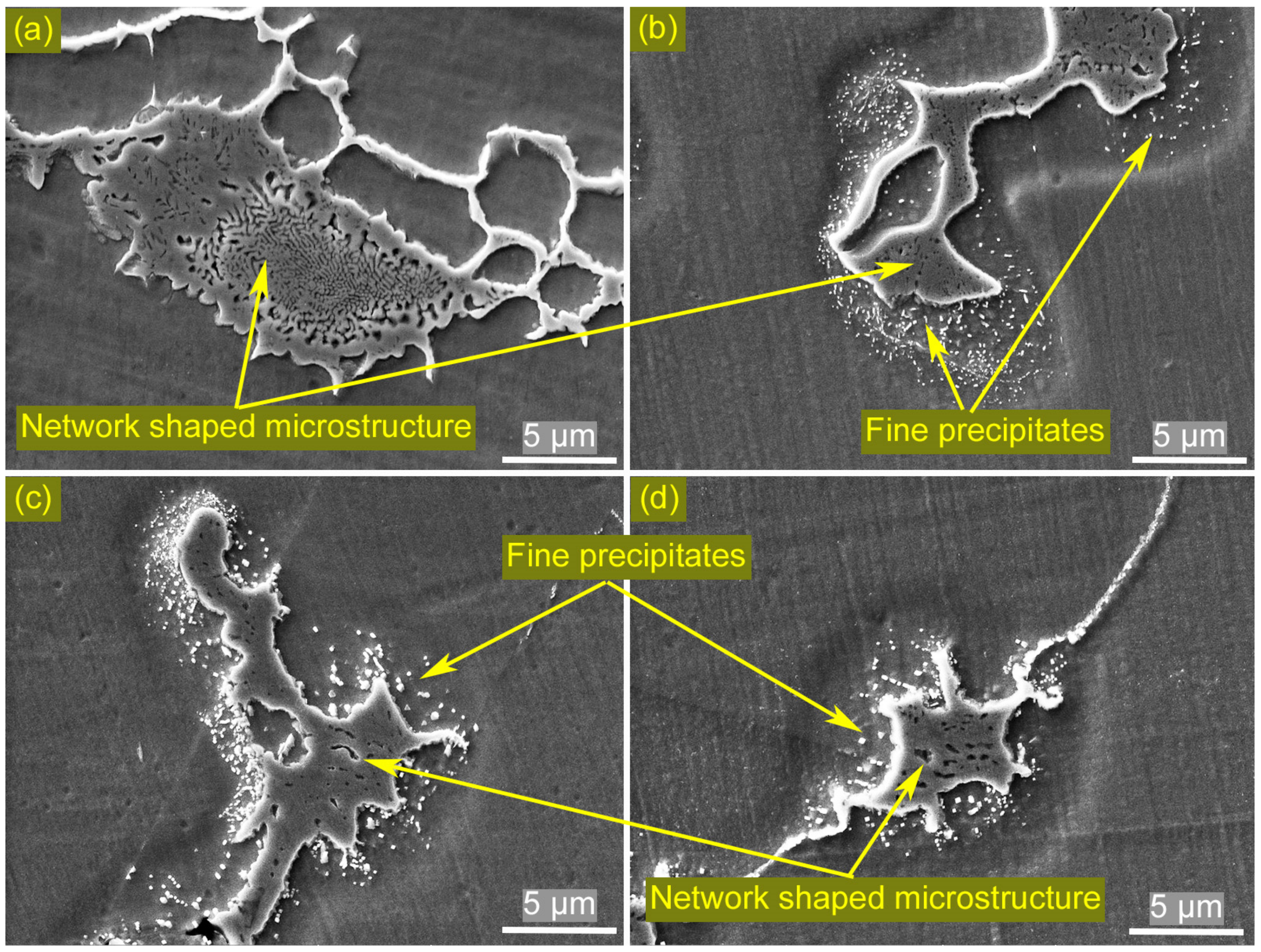
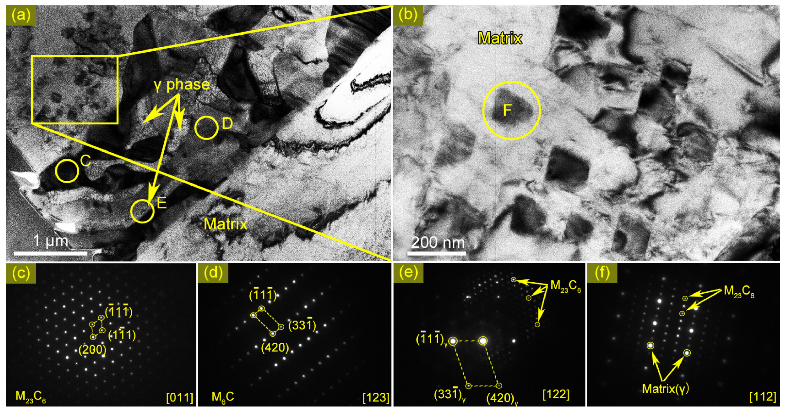
3.4. Identification of the Eutectic Microstructure in HAZ

The TEM specimen was prepared using FIB, as shown by the dotted rectangle indicated in Figure 4e. The specimen contained network-shaped microstructure with fine precipitates around it. Crystal and composition information were obtained by SAED and EDX, respectively.
Figure 7a shows the morphology of the network-shaped microstructure by TEM and Figure 7b presents the magnified image of the fine precipitates. Table 4 lists the chemical compositions of these phases. It is clearly demonstrated that the network-shaped microstructure is composed of three constituents with distinct morphologies, which are exhibited in the black, gray, and white zones marked by C, D, and E, respectively. The intervals between the black or gray zones are filled with the white ones, which means that the black/gray zones and the white zones appear alternatively, similar to the eutectic microstructures. SAED and EDX results confirm that the black, gray, and white zones are M23C6, M6C, and γ (matrix), respectively. It is noted that M6C has a similar crystal structure to M23C6, but a higher Mo concentration [27,28,29]. In Figure 4g,h, the red zones are supposed to be M6C due to Mo enrichment, and the Cr-enriched zones are M23C6 phase. Fine precipitates around the network-shaped microstructure shown in Figure 4d,e are also observed by TEM and present as a cuboidal shape with a size of about 200 nm, marked by F in Figure 7b. The fine precipitates are also identified to be M23C6-type carbides by SAED, as shown in Figure 7f.

4. Discussion

Based on the observation of microstructures in real welded joints and simulated HAZ specimens, it is confirmed that the morphology of precipitates in HAZ is altered by peak temperatures and thermal cycle numbers. Precipitates adjacent to the fusion line (Figure 4e) and in specimens subjected to the peak temperature of 1300 °C (Figure 5d) present a network shape, similar to the eutectic microstructure, which is presumably related to the liquation phenomenon and eutectic reaction. Further, welding thermal simulations confirm that the eutectic microstructure is transformed from coarse precipitates along grain boundaries in BM, which are identified as M23C6 carbides by TEM.
The liquation of M23C6 carbides during the rapid heating process provided by welding can be explained by the constitutional liquation mechanism. The mechanism of constitutional liquation of M23C6 carbides in the present work can be illustrated as follows.
Figure 8 is a schematic binary phase diagram between γ (matrix) and M23C6 carbides and Figure 9 is a schematic illustration of M23C6 evolutionary behavior during welding thermal simulation. It is obvious that the chemical composition of the as-received BM, C0, is located in the two-phase region due to the coexistence of γ and M23C6. It is well known that under equilibrium conditions, phase transformation will take place along the blue dotted vertical line that goes through C0 by elevating the temperature. When the temperature reaches 1300 °C, there is no liquid. However, for the non-equilibrium heating process of welding, the phase transformation would be different. Rapid heating permits insufficient time for solute atoms such as Cr released from the partially dissolved M23C6 carbides to diffuse into the surrounding matrix (γ phase). In this way, the surrounding matrix was Cr saturated, causing the chemical composition of the adjacent matrix to change along the solvus from points 1 to 3. Once the chemical composition of adjacent matrix reaches point 3, the eutectic reaction γ + M23C6 → liquid will occur between the matrix and adjacent incompletely dissolved M23C6 carbides. A small amount of liquid forms by eutectic reaction, as shown in Figure 9a‒c. To simplify matters, we can move the blue dotted line to the red dotted line, which will not change the nature of the problem. It is obvious that as the temperature increases from eutectic temperature to 1300 °C, the amount of liquid increases (Figure 9d), and the chemical composition of γ varies along solidus from point 3 to 4. At the same time as the liquid phase is formed, the migration of grain boundary also occurs in HAZ. Some migrated grain boundaries will meet the liquid phase, allowing the liquid phase to penetrate the grain boundaries [30].
The liquation process mentioned above is highly related to the heating rate. If the heating rate is slow enough, the M23C6 carbides will be dissolved completely in the matrix before the temperature reaches the eutectic point. If the heating rate is rapid, insufficient diffusion of solute atoms will result in incomplete dissolution of M23C6 carbides, leading to a eutectic reaction between the survived M23C6 carbides and the matrix when the temperature reaches the eutectic point. The same network-shaped microstructures in HAZ are observed in the thermal simulation samples (shown in Figure 5c,d and Figure 6), meaning a similar liquation process to that in HAZ occurs in these samples. The difference in heating rate does not change the nature of the liquation process that occurs in HAZ and the thermal simulations, but may affect the degree of liquation, which is reflected in the volume of the liquid phase generated. In addition, the contribution of boron to HAZ liquation cannot be ignored. Figure 10 shows the distribution maps of Cr, B, and C under as-received condition. It can be seen that boron is enriched in M23C6 carbides (Figure 10c). Boron promotes HAZ liquation by two mechanisms. First, boron in M23C6 carbides can lower the liquation temperature [31,32,33], making liquation more likely to occur during the heating process. Moreover, boron released from dissolved M23C6 carbides can lower the solid/phase surface energy, promoting the liquid phase to penetrate grain boundaries [16,30].
After holding at a peak of 1300 °C, the temperature starts to decrease, and some liquid transforms into austenite, of which the chemical composition varies along solidus from point 4 to 3. Once the temperature reaches the eutectic line, a eutectic reaction occurs, by which the residual liquid transforms into eutectic constituents, namely γ and M23C6 or M6C (depending on the relative concentration of Mo and Cr) simultaneously, as shown in Figure 9e.
It should be noted that the austenite that forms before eutectic reaction will be Cr supersaturated once the temperature decreases below T1, as shown in Figure 8, due to the rapid cooling rate not providing enough time for Cr atoms to diffuse to form carbides. The zone of supersaturated austenite corresponds to the sunk zone surrounding eutectic microstructure, as shown in Figure 5d. If the specimen is exposed to a secondary thermal cycle, there will be a chance for the supersaturated Cr atoms to precipitate as carbides. In the present thermal simulation, the peak temperature of the second thermal cycle is set as 1100 °C, at which point it is assumed that the maximum solid solubility of Cr (C1100) is lower than that at 1300 °C (C1300), as shown in Figure 8. At 1100 °C, combined with proper holding time (≥5 s), fine carbides (M23C6) will precipitate in the supersaturated zone (Figure 9f); that is why there is such a large number of fine precipitates around the eutectic microstructure in the real multilayer welded joints and simulated specimens subjected to two thermal cycles.
Although constitutional liquation of M23C6 carbides occurs in HAZ during welding heating process, no cracking has been found in welded joints. Liquation cracking occurs, combined with the presence of liquid phase on grain boundary and the thermal tensile stress [34]. The liquid film weakens grain boundary adhesive strength, and liquation cracking forms when the thermal tensile stress exceeds the grain boundary adhesive strength. The relationship between the tensile stress σ required to separate the liquid filled grain boundary and the thickness of the liquid film h is given by Miller et al. [35]: σ = γSL/2h, while γSL is the solid/phase surface energy. According to this relationship, the weakening effect of the liquid film on grain boundary will be stronger with h increasing. As stated earlier, the liquid film is produced by a eutectic reaction of partially dissolved M23C6 carbides and the matrix, which means the thickness of liquid film is directly related to the dimension of the M23C6 carbides. It can be inferred that liquation cracking could be avoided by controlling the size of M23C6 carbides and the welding heating input. In the present research, no liquation cracking found in the welded joint indicates that GTAW is a suitable method to join alloy 617B.

5. Conclusions

In the present study, the mechanism for HAZ liquation in the alloy 617B welded joint was investigated. The following four conclusions can be drawn according to the current results.
1. Liquation occurs in HAZ close to the fusion line of the alloy 617B GTAW welded joint. The morphology and the chemical composition of particles in HAZ are altered because of the liquation phenomenon. No liquation cracking has been found in HAZ under the current welding conditions.
2. Constitutional liquation of large M23C6 carbides during a rapid heating process is responsible for HAZ liquation of the 617B welded joint. Rapid heating means the solute atoms Cr and Mo released from partially dissolved M23C6 carbides do not have enough time to diffuse into the matrix, resulting in eutectic reaction M23C6+γ → liquid in the temperature range from 1250 °C to 1300 °C. The liquid phase transforms into γ and carbides (M23C6 or M6C) simultaneously, namely a eutectic microstructure, during the subsequent cooling process.
3. The presence of the fine precipitates is related to the multiple thermal cycles that HAZ is subjected to in real welded joints. The first thermal cycle with higher peak temperatures leaves the zone around the eutectic microstructure supersaturated in Cr after cooling, and the second thermal cycle with a lower peak temperature provides a suitable combination of temperature and time for Cr to precipitate from the matrix.
4. Boron in alloy 617B is found to be enriched in M23C6 carbides. Boron is expected to promote HAZ liquation by lowering the liquation temperature of M23C6 carbides and promoting the liquid phase to penetrate grain boundaries.

Author Contributions

Conceptualization: S.L., K.L., and Z.C.; methodology: S.L., M.H., and Y.W.; resources: Z.C. and J.P.; writing—original draft preparation: S.L.; writing—review and editing: K.L. and Z.C.; project administration: K.L., Z.C., and J.P. All authors have read and agreed to the published version of the manuscript.

Funding

This research was funded by the National Natural Foundation of China (Project Nos. 51775300 and NO. 51901113) and the Tribology Science Fund of the State Key Laboratory of Tribology in Tsinghua University (Project No. SKLT2015A02).

Acknowledgments

The authors are grateful for Anli Lu and Jialie Ren, who provided important advice on the present work. Rong Wang and Wenyan Yang, Senior Engineers in the State Key Laboratory of Tribology, helped us finish the SEM and FIB experiments, for which we are grateful.

Conflicts of Interest

The authors declare no conflict of interest.

References

  1. Viswanathan, R.; Henry, J.F.; Tanzosh, J.; Stanko, G.; Shingledecker, J.; Vitalis, B.; Purgert, R.U.S. Program on materials technology for ultra-supercritical coal power plants. J. Mater. Eng. Perform. 2005, 14, 281–292. [Google Scholar] [CrossRef]
  2. Klöwer, J.; Husemann, R.U.; Bader, M. Development of nickel alloys based on alloy 617 for components in 700 °C power plants. Procedia Eng. 2013, 55, 226–231. [Google Scholar] [CrossRef] [Green Version]
  3. Ren, W.J.; Lu, F.G.; Yang, R.J.; Liu, X.; Li, Z.G. Liquation cracking in fiber laser welded joints of inconel 617. J. Mater. Process. Technol. 2015, 226, 214–220. [Google Scholar] [CrossRef]
  4. Ojo, O.A.; Richards, N.L.; Chaturvedi, M.C. Contribution of constitutional liquation of gamma prime precipitate to weld HAZ cracking of cast Inconel 738 superalloy. Scr. Mater. 2004, 50, 641–646. [Google Scholar] [CrossRef]
  5. Qian, M.; Lippold, J.C. The effect of annealing twin-generated special grain boundaries on HAZ liquation cracking of nickel-base superalloys. Acta Mater. 2003, 51, 3351–3361. [Google Scholar] [CrossRef]
  6. Cieslak, M.J.; Stephens, J.J.; Carr, M.J. A study of the weldability and weld related microstructure of cabot alloy 214. Metall. Trans. A 1988, 19, 657–667. [Google Scholar] [CrossRef]
  7. Cieslak, M.; Headley, T.; Romig, A. The welding metallurgy of HASTELLOY alloys C-4, C-22, and C-276. Metall. Trans. A 1986, 17, 2035–2047. [Google Scholar] [CrossRef]
  8. Taheri, M.; Halvaee, A.; Kashani-Bozorg, S.F. Effect of Nd: YAG pulsed-laser welding parameters on microstructure and mechanical properties of GTD-111 superalloy joint. Mater. Res. Express 2019, 6, 1–15. [Google Scholar] [CrossRef]
  9. Zhan, X.; Li, D.; Li, Y.; Lu, S. The influence of niobium on the plastic deformation behaviors of 310s austenitic stainless steel weld metals at different temperatures. Mater. Sci. and Eng. A-Struct. Mater. Prop. Microstruct. Process. 2019, 743, 648–655. [Google Scholar] [CrossRef]
  10. Robino, C.; Cieslak, J. Solidification and welding metallurgy of thermo-span alloy. Sci. Technol. Weld. Join. 1997, 2, 220–230. [Google Scholar] [CrossRef]
  11. Lippold, J. An investigation of weld cracking in alloy 800. Weld. J. 1983, 63, 91–103. [Google Scholar]
  12. Lippold, J.; Baeslack, W.; Varol, I. Heat-affected zone liquation cracking in austenitic and duplex stainless steels. Weld. J. (USA) 1988, 71, 1–14. [Google Scholar]
  13. Klöwer, J. Alloy 617 and derivatives. In Materials for Ultra-Supercritical and Advanced Ultra-Supercritical Power Plants; Woodhead Publishing: Cambridge, UK, 2017; pp. 547–570. [Google Scholar]
  14. Vishwakarma, K.R.; Chaturvedi, M.C. Effect of boron and phosphorus on HAZ microfissuring of Allvac 718 Plus superalloy. Mater. Sci. Technol. 2009, 25, 351–360. [Google Scholar] [CrossRef]
  15. Van, G.T.; Carron, D.; Le Masson, P.; Robin, V.; Andrieu, A.; Stodolna, J. Effect of boron content on hot ductility and hot cracking susceptibility in 316L austenitic stainless steel for welding components. J. Mater. Eng. Perform. 2018, 27, 5114–5123. [Google Scholar] [CrossRef]
  16. Li, Q.; Lin, X.; Wang, X.; Yang, H.; Song, M.; Huang, W. Research on the grain boundary liquation mechanism in heat affected zones of laser forming repaired K465 nickel-based superalloy. Metals 2016, 6, 64. [Google Scholar] [CrossRef] [Green Version]
  17. Pepe, J. Effects of constitutional liquation in 18-Ni maraging steel weldments. Weld. J. 1967, 46, 411–422. [Google Scholar]
  18. Duvall, D. Further heat-affected-zone studies in heat-resistant nickel alloys. Weld. J. 1967, 46, 423–432. [Google Scholar]
  19. Owczarski, W.; Duvall, D.; Sullivan, C. A model for heat affected zone cracking in nickel-based alloys. Weld. J. 1966, 45, 145. [Google Scholar]
  20. Thompson, R. The relationship between grain size and microfissuring in alloy 718. Weld. J. 1985, 64, 91s–96s. [Google Scholar]
  21. Baeslack, W.A.; Nelson, D. Morphology of weld heat-affected zone liquation in cast alloy 718. Metallography 1986, 19, 371–379. [Google Scholar] [CrossRef]
  22. Phuraya, N.; Phung-On, I.; Terasaki, H.; Komizo, Y. Direct observation of liquation in Ni-base superalloy by using confocal laser scanning microscopy. Key Eng. Mater. 2015, 658, 36–41. [Google Scholar] [CrossRef]
  23. Xu, H.; Liu, W.; Lu, F.; Wang, P.; Ding, Y. Evolution of carbides and its characterization in HAZ during NG-TIG welding of Alloy 617B. Mater. Charact. 2017, 130, 270–277. [Google Scholar] [CrossRef]
  24. Fink, C.; Zinke, M. Welding of nickel-based alloy 617 using modified dip arc processes. Weld. World 2013, 57, 323–333. [Google Scholar] [CrossRef]
  25. Kou, S. Welding Metallurgy; John Wiley & Sons: Hoboken, NJ, USA, 2003; pp. 55–56. [Google Scholar]
  26. Tytko, D.; Choi, P.-P.; Klöwer, J.; Kostka, A.; Inden, G.; Raabe, D. Microstructural evolution of a Ni-based superalloy (617B) at 700 C studied by electron microscopy and atom probe tomography. Acta Mater. 2012, 60, 1731–1740. [Google Scholar] [CrossRef]
  27. Jo, T.S.; Lim, J.H.; Do Kim, Y. Dissociation of Cr-rich M23C6 carbide in alloy 617 by severe plastic deformation. J. Nucl. Mater. 2010, 406, 360–364. [Google Scholar] [CrossRef]
  28. Inoue, A.; Masumoto, T. Carbide reactions (M3C→M7C3→M23C6→M6C) during tempering of rapidly solidified high carbon Cr-W and Cr-Mo steels. Metall. Trans. A 1980, 11, 739–747. [Google Scholar] [CrossRef]
  29. Kuo, K.; Jia, C. Crystallography of M23C6 and M6C precipitated in a low alloy steel. Acta Metall. 1985, 33, 991–996. [Google Scholar] [CrossRef]
  30. Chen, W.; Chaturvedi, M.C.; Richards, N.L. Effect of boron segregation at grain boundaries on heat-affected zone cracking in wrought INCONEL 718. Metall. Mater. Trans. A 2001, 32, 931–939. [Google Scholar] [CrossRef]
  31. Huang, X.; Chaturvedi, M.C.; Richards, N.L.; Jackman, J. The effect of grain boundary segregation of boron in cast alloy 718 on HAZ microfissuring—A SIMS analysis. Acta Mater. 1997, 45, 3095–3107. [Google Scholar] [CrossRef]
  32. Guo, H.; Chaturvedi, M.C.; Richards, N.L. Effect of boron concentration and grain size on weld heat affected zone microfissuring in Inconel 718 base superalloys. Sci. Technol. Weld. Join. 2013, 4, 257–264. [Google Scholar] [CrossRef]
  33. Ojo, O.A. Intergranular liquation cracking in heat affected zone of a welded nickel based superalloy in as cast condition. Mater. Sci. Technol. 2007, 23, 1149–1155. [Google Scholar] [CrossRef]
  34. Böllinghaus, T.; Herold, H. Hot Cracking Phenomena in Welds; Springer: Berlin/Heidelberg, Germany, 2005. [Google Scholar]
  35. Miller, W.A.; Chadwick, G.A. On the magnitude of the solid/liquid interfacial energy of pure metals and its relation to grain boundary melting. Acta Metall. 1967, 15, 607–614. [Google Scholar] [CrossRef]
Figure 1. Schematic diagram of (a) the set-up structure and (b) groove of 617B GTAW (mm). (c) Micrograph of welded joint section (OM).
Metals 10 00094 g001
Figure 2. Temperature‒time curves of thermal simulations: (a) one thermal cycle and (b) two thermal cycles.
Metals 10 00094 g002
Figure 3. Microstructure of 617B BM under the as-received condition: (a) OM, (b) SEM, (c) TEM, and SAED, (d) EDX result of the carbide in (c).
Metals 10 00094 g003
Figure 4. Microstructure of the welded joint including HAZ and WM. (a) OM; (b) is a magnified image of HAZ in (a) obtained by SEM; (ce) are magnified zones marked by red/blue/yellow rectangles in (b) obtained by SEM, respectively; (fh) are chemical compositional mappings of microstructures in (ce), respectively.
Metals 10 00094 g004
Figure 5. Microstructures observed by SEM after thermal simulation with varied peak temperatures (a) Tp1 = 1200 °C, tp1 = 0.5 s, (b) Tp1 = 1250 °C, tp1 = 0.5 s, (c) and (d) Tp1 = 1300 °C. tp1 = 0.5 s.
Metals 10 00094 g005
Figure 6. Microstructure images obtained by SEM after thermal simulations with two thermal cycles. The peak temperature of the second thermal cycle Tp2 was 1100 °C and the holding time tp2 were (a) 1 s, (b) 5 s, (c) 10 s, and (d) 20 s.
Metals 10 00094 g006
Figure 7. TEM images of network-shaped microstructure: (a) bright field; (b) bright-field image of fine precipitates; (c)‒(e) are SAED patterns of zones C, D, and E marked in (a), respectively; (f) SAED pattern of fine precipitates marked by F in (b).
Metals 10 00094 g007
Figure 8. A schematic binary phase diagram between γ phase and M23C6 carbides.
Metals 10 00094 g008
Figure 9. Schematic illustration of M23C6 evolutionary behavior during welding thermal simulation.
Metals 10 00094 g009
Figure 10. (a) SEM micrograph of BM and SIMS micrographs of (b) Cr+, (c) B+ and (d) C+ distribution in (a).
Metals 10 00094 g010
Table 1. Chemical compositions of BM and filler metal (wt %).
ElementsCCoCrFeMoTiAlNbBNi
BM0.05212.0522.380.339.020.441.030.030.0045Bal.
Filler metal0.0711.2022.50-8.900.391.27--Bal.
Table 2. Welding parameters of GTAW.
Current (A)Voltage (V)Welding Speed (cm/min)Heat Input (kJ/cm)
180128–916–19
Table 3. Chemical compositions measured by EDX in SEM: the Cr-rich phase (EDX A in Figure 4g) and Mo-rich phase (EDX B in Figure 4g) (wt %).
ElementsCAlTiMoCrCoNi
Cr-rich phase (A)2.260.41-24.3150.035.9417.04
Mo-rich phase (B)1.510.511.6746.4821.267.9220.70
Table 4. Chemical compositions measured by EDX in TEM: M23C6 (C in Figure 7a) and M6C (D in Figure 7a) in a network-shaped structure and M23C6 in fine precipitates (F in Figure 7a) (wt %).
ElementsCAlTiMoCrCoNi
M23C6 in network-shaped structure4.20.3-21.738.46.321.1
M6C in network-shaped structure3.60.530.234.628.35.820.3
M23C6 in fine precipitates3.50.48-24.829.58.730.8

