Article

Investigation on Fracture of a 6014-T4 Aluminum Alloy Sheet in the Flanging and Hemming Process Based on Numerical and Experimental Methods

1
Key Laboratory of Automobile Materials, College of Materials Science and Engineering, Jilin University, Changchun 130022, China
2
Roll Forging Research Institute, Jilin University, Changchun 130022, China
*
Author to whom correspondence should be addressed.
Metals 2020, 10(1), 81; https://doi.org/10.3390/met10010081
Submission received: 7 December 2019 / Revised: 26 December 2019 / Accepted: 27 December 2019 / Published: 3 January 2020

Abstract

:
The fracture of a flat-surface straight-edge hemmed component of aluminum alloy sheets was investigated in this study. The specimen was made of 1 mm thick 6014-T4. Natural aging characteristics of 6014-T4 were studied via uniaxial tensile tests. The results show that the yield stress and ultimate tensile strength increased while the uniform elongation, strain hardening exponent, and plastic strain ratio decreased during the natural aging period, which worsened the formability. The sheet was biaxially stretched to obtain a pre-strain before the flanging and hemming operation. The influence of the flanging radius on the fracture was evaluated using experimental and numerical methods, and the optimum values were obtained. The comparison between the roller hemming and die hemming process proved that the former tends to produce better formability.

1. Introduction

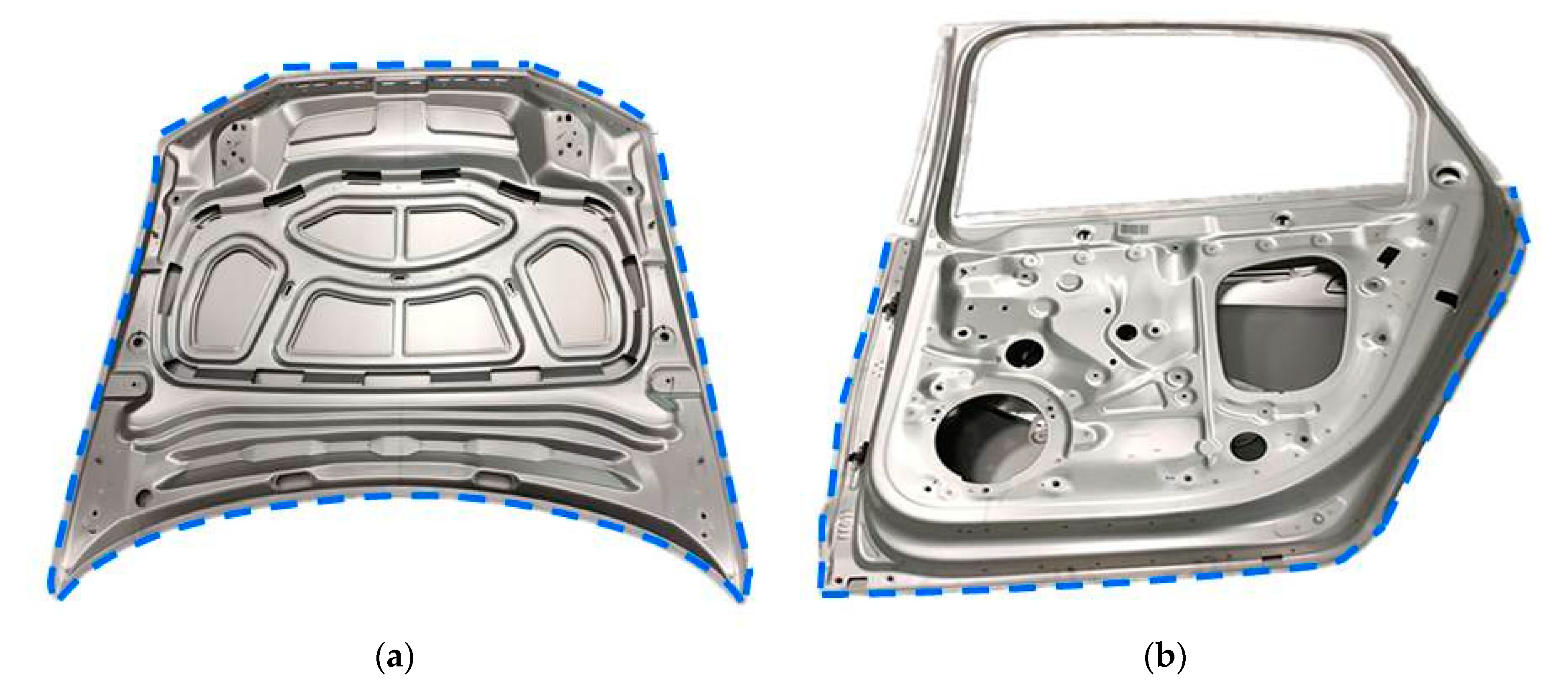
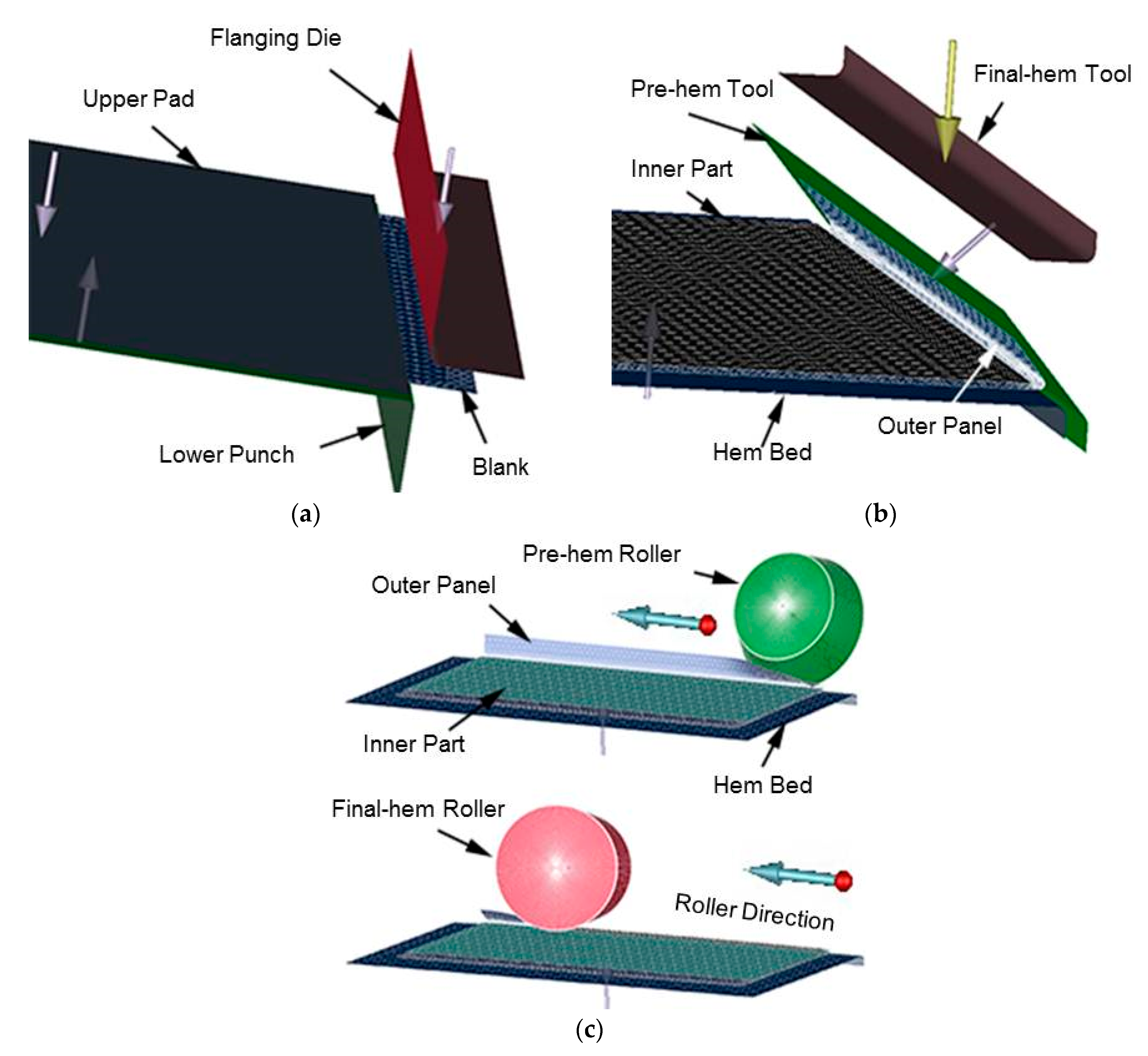
Hemming is a typical assembly process in which the edge of the outer panel of an automobile component is folded over the edge of the inner part [1]. Figure 1 illustrates the typical three-step bending process of the hemming operation comprising of the flanging, pre-hemming, and final hemming process. This assembly method is widely used in the final stages of production of automobile hoods, doors, or other closures for aesthetic purposes (c.f. Figure 2).
In the hemming process, a severely localized plastic deformation occurs primarily on the convex surface of the outer panel, which may lead to material damage especially for aluminum alloy sheet due to its lower formability as compared with steel [2]. Owing to its light-weight design, aluminum alloy is commonly used to produce the outer panels of middle and high-end vehicles instead of the steel sheet. Thus, it is particularly important to accurately predict and effectively improve the fracture during the flanging and hemming process in the design stage. The finite element method (FEM) provides a route to address the formability issues in advance. In recent years, FEM has proved to be able to well simulate the sheet metal forming process [3].
Some research has already been done on the formability of aluminum alloy sheet in the bending and hemming process. Thuillier et al. [4,5] established a ductile damage model based on critical void volume fraction which was identified from macroscopic tests and further investigated the macroscopic variables and crack development in the bent area of AA6016-T4 aluminum sheet using numerical and experimental tests. Li et al. [6] developed a method that can be used to investigate the cyclic hardening behavior during the hemming process. Liewald et al. [7] studied the surface roughening of AA6016-T4 aluminum sheet during the bending and hemming process. Muhammad et al. [8] studied the relationship between the bendability and microstructure of AA6016 via a series of wrap-bend tests.
As can be seen, the primary focus of previous works has been on the bending or hemming operation. However, formability under hemming is closely related to the forming process of the single outer panel. In addition to the forming process, the age hardening of heat treatable aluminum sheet also significantly influences the hemming formability. Engler et al. [9,10] studied the impact of a combination of natural aging and pre-straining on the strength and anisotropy of AA 6016. As always, it is stipulated that the aluminum alloy sheet 6014-T4 should be used within six months since the solution treatment in practical production due to natural aging effect. However, the systematic research on the influence of changes in mechanical properties on the bendability and fracture is still insufficient.
In this study, a flat surface-straight edge hemmed component made of 6014-T4 aluminum alloy sheet, which is extensively used in automobile outer panels, was designed in view of minor influence of curvature on fracture. The chemical composition of 6014-T4 sheet supplied by West Aluminum China was determined by photoelectric direct reading spectral technique on the SPECTROMAXx stationary metal analyzer (Spectro, Kleve, Germany), as listed in Table 1. The thickness of the inner and outer panel was 1 mm. The experimental and numerical methods were used to assess the influence of age hardening and forming process on the fracture. The same boundary conditions were applied for both the experiments and simulation.

2. Methods

2.1. Mechanical Property Experiments

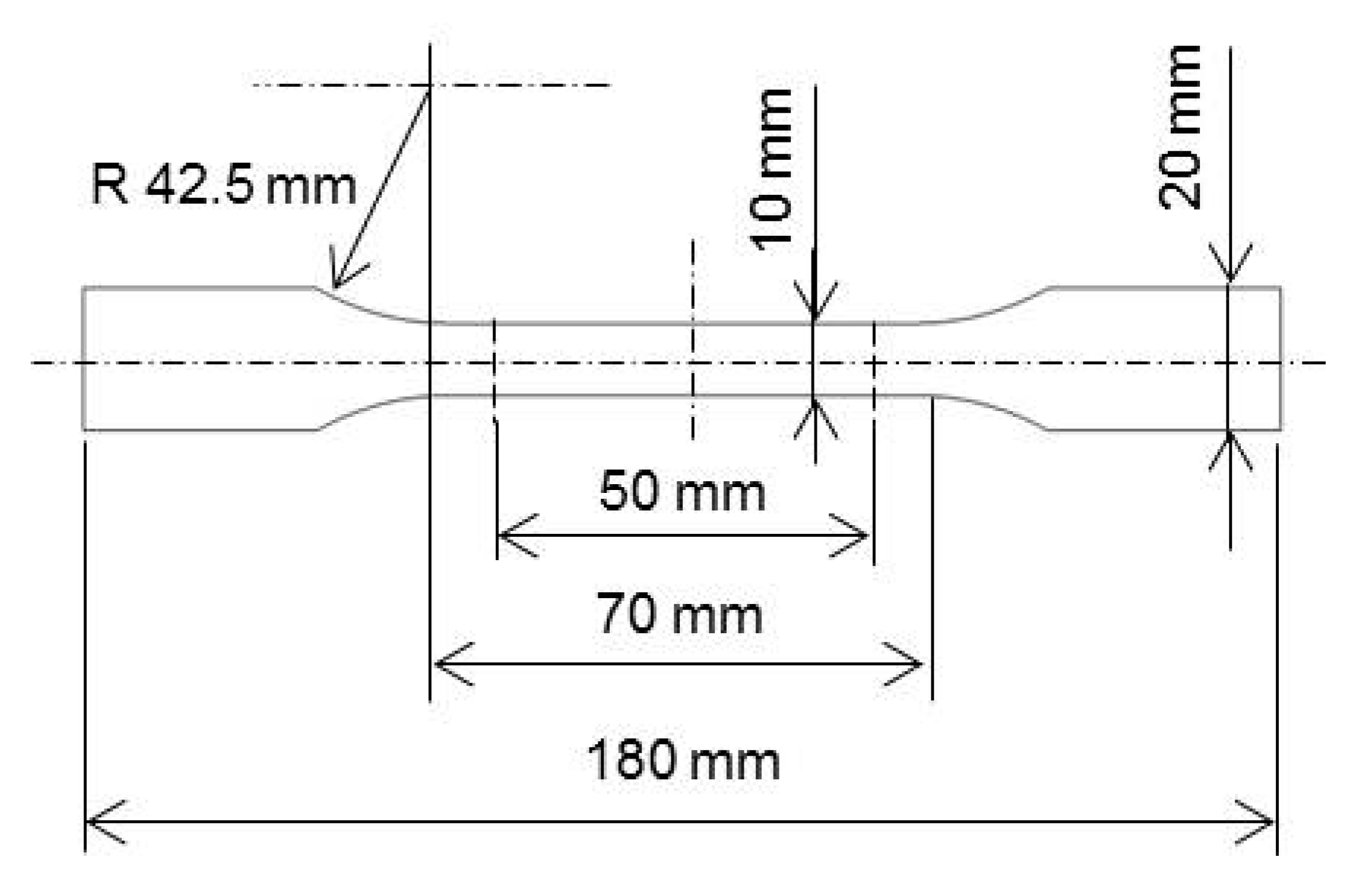
The macro-characteristics of age hardening was investigated via uniaxial tensile tests at room temperature by using a MTS-810 servo hydraulic experiment. During the first six months after solution treatment, the tensile tests of 6014-T4 aluminum sheet were conducted every month. Solution heat treatment was performed in an air furnace at 540 ± 2 °C for 1 h followed by quenching into ice water for tensile specimens. The mechanical properties from the tensile testing are the yield stress, ultimate tensile strength, uniform elongation (Ag), strain hardening exponent (n-value) and plastic strain ratio (r-value). Tensile specimens in accordance with ISO 6892-1:2009 standard (Figure 3) were cut along the rolling direction (0°, 45°) to the rolling direction and in the transverse direction (90°). The gauge length of the specimen was 50 mm. Two contact extensometers were used to measure the longitudinal and transverse strain of the tensile specimens. The specimens were stretched to fracture at a constant stretching rate of 5 mm/min to obtain the stress-strain curves, yield stress, ultimate tensile strength, and uniform elongation (Ag). Three specimens were taken for each orientation (0°, 45°, and 90°), and then averaged value was obtained. The n-value was determined between 2% and 20% strain, as per ISO 10275:2007. The r-value was obtained in the same conditions as per ISO 10113:2006. Similarly, three specimens extracted in each direction were tested and averaged to evaluate the n-value and r-value.
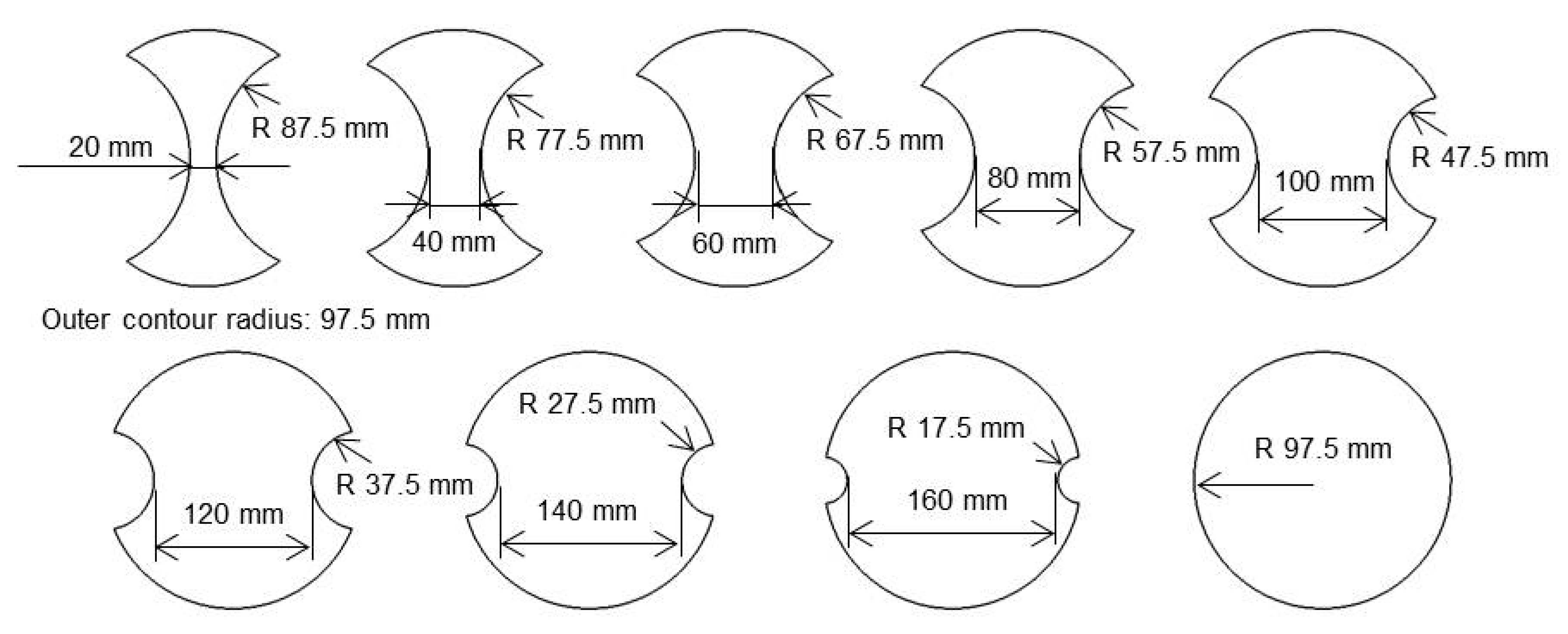
The forming limit curve (FLC) of 6014-T4 was determined on a home-made Erichsen model laboratory press (Genbon, Shanghai, China) based on the Nakazima cup test according to ISO 12004:2008. The GOM Aramis optical measuring system was used to capture the necked points of the specimens. The size of the standard specimens was shown in Figure 4. The specimens of the same size were tested three times, and then the average was calculated to fit the FLC in Origin software (Pro 8, Originlab, Northampton, MA, USA). The specimens were measured along the rolling direction. All measured strains in the Nakazima tests were corrected to the mid-plane. In this study, the forming limit curves after the natural aging time for 1 month, 2 months, and 3 months were used in the subsequent corresponding simulation.

2.2. Forming Tests

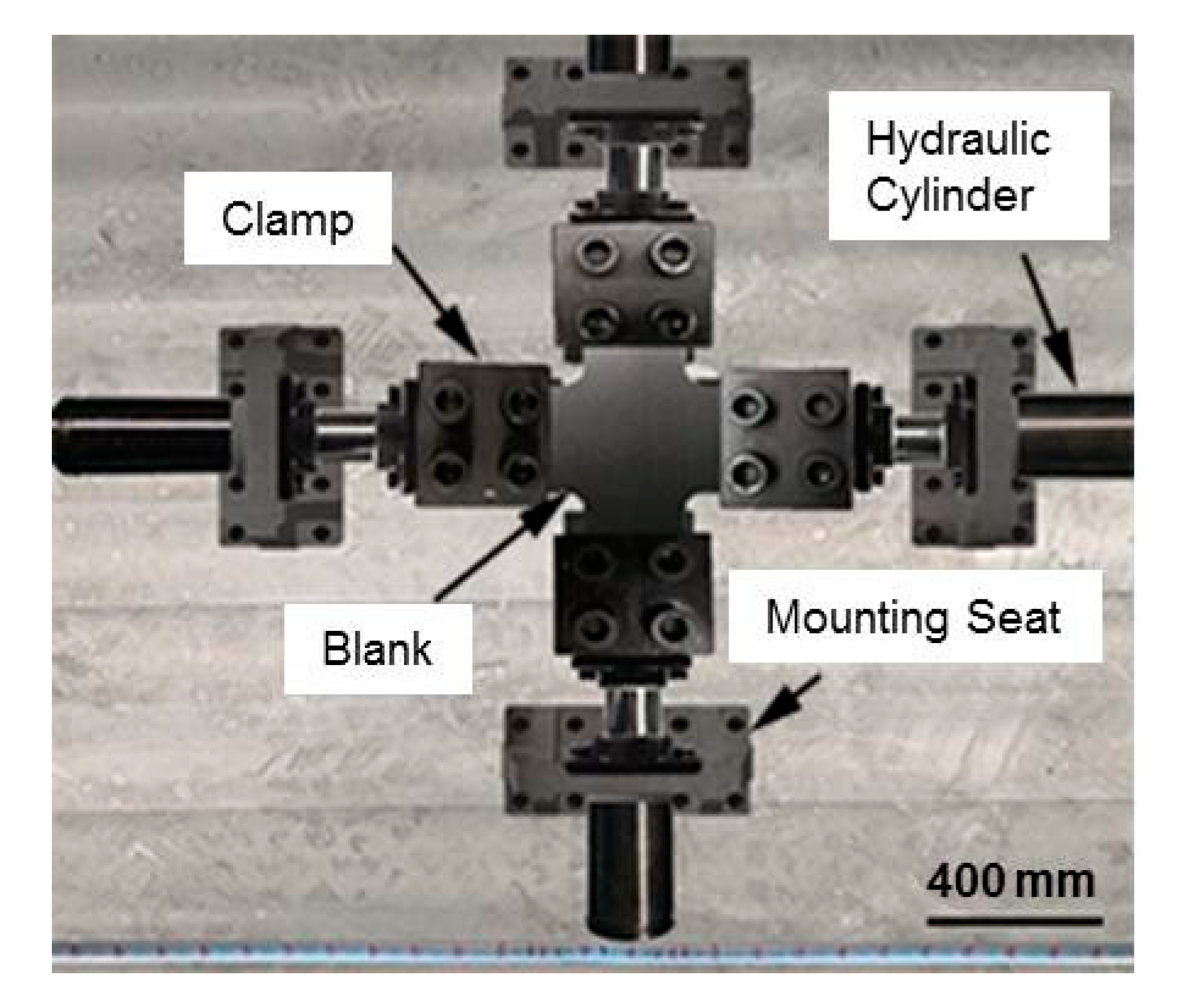
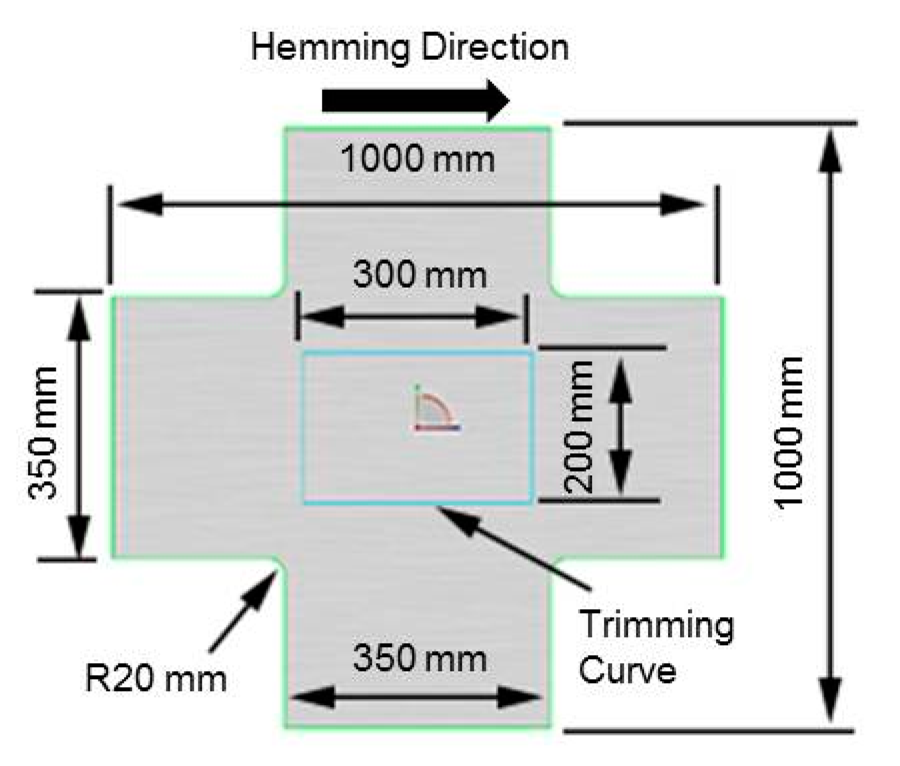
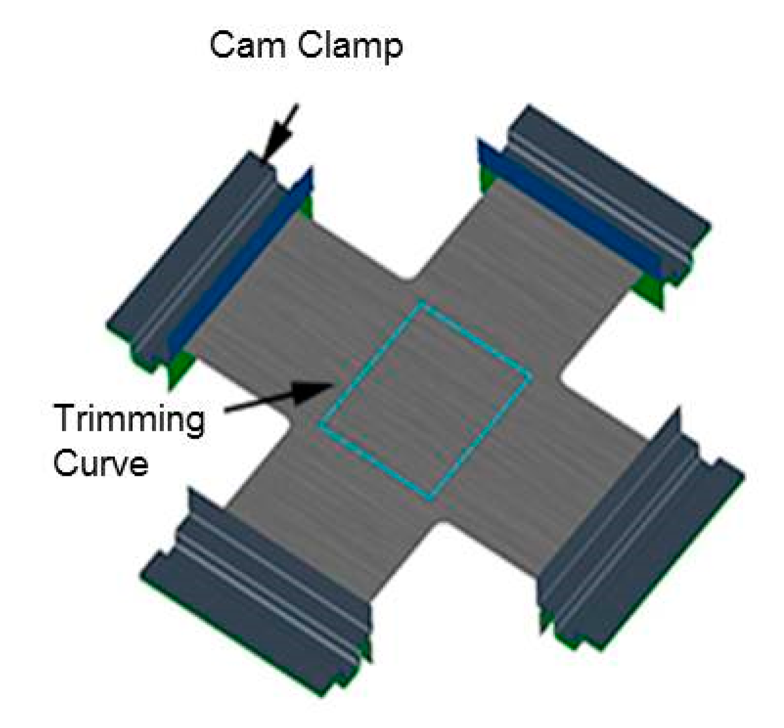
The biaxial tensile experiments were performed on an electro-hydraulic controlled cross stretching equipment with independently adjustable displacements in two vertical directions (see Figure 5). The displacement in the hemline direction was set at 15 mm and while that in the perpendicular direction was 24 mm to ensure that the test piece contain a pre-strain of 5% along the hemline direction (perpendicular to rolling direction) and 12% pre-strain perpendicular to the hemline in reference to the strain distribution of an actual drawing part of an outer door panel. The original blank size is clear in Figure 6. The stretching in both directions was completed in the same time. After biaxial stretching, the pre-strain sheet was trimmed into the size of 300 mm × 200 mm using MITSUBISHI HVII 2D laser cutting machine (Mitsubishi Electric, Tokyo, Japan), as shown in Figure 6. The final blank after trimming was used in the flanging and hemming experiments.
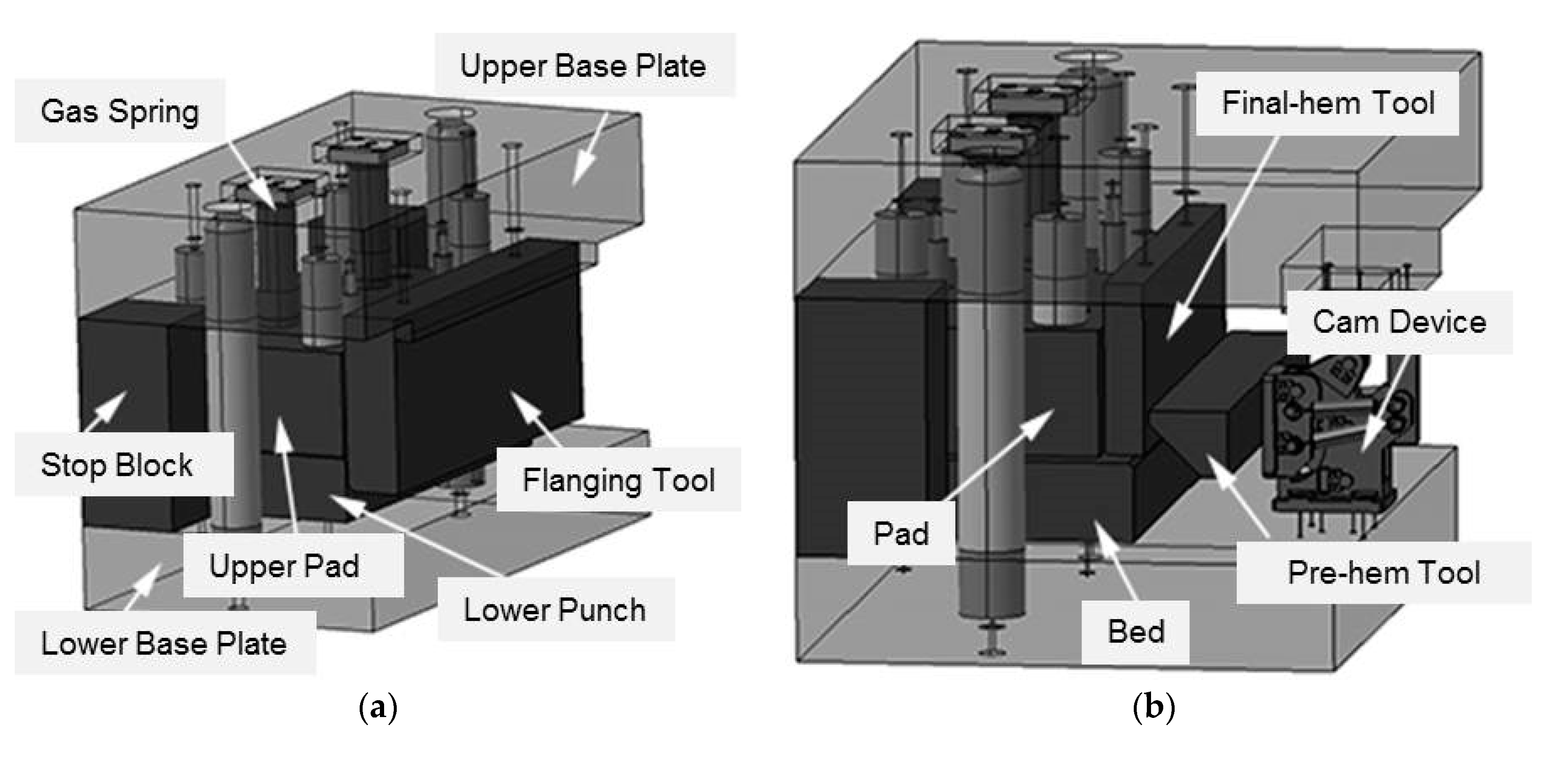
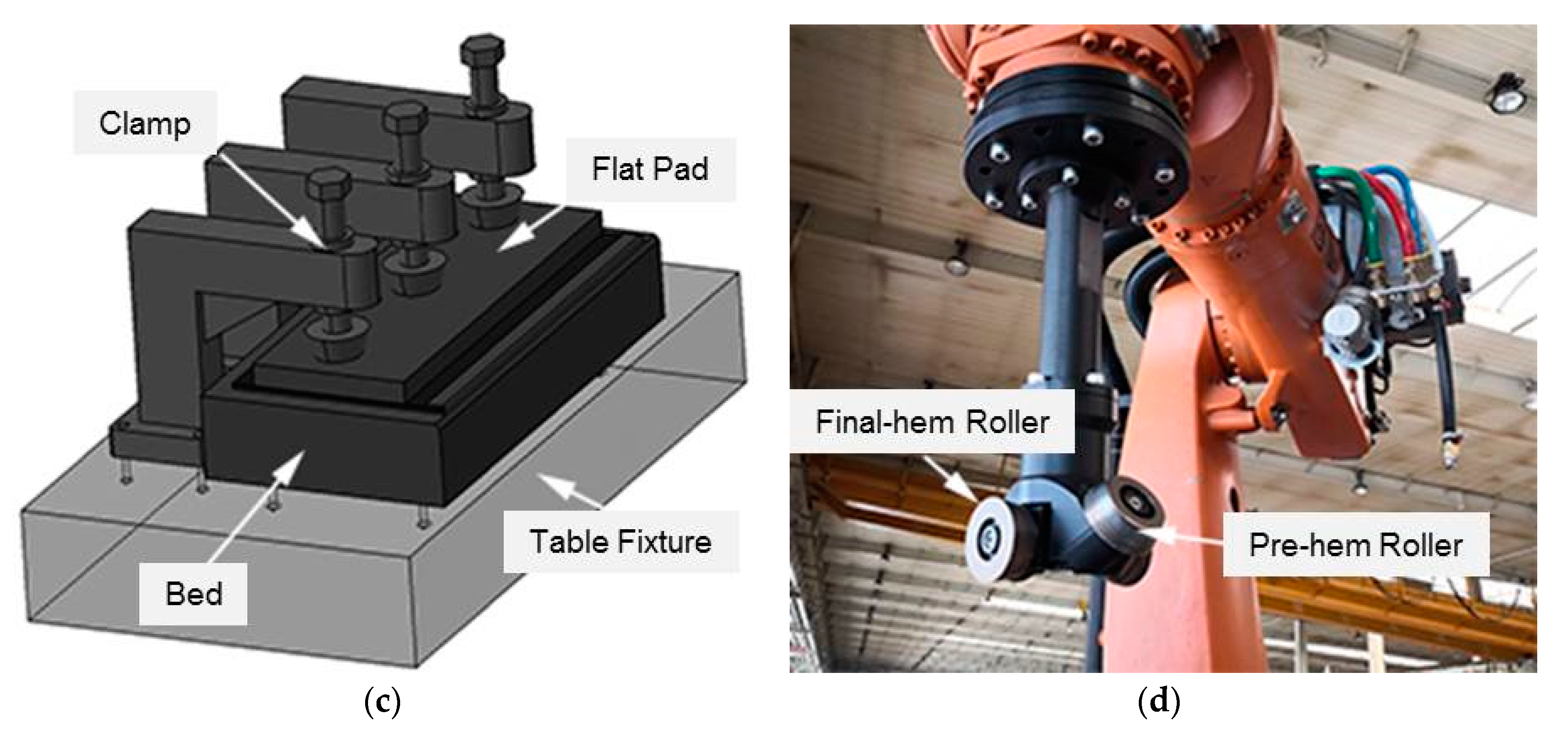
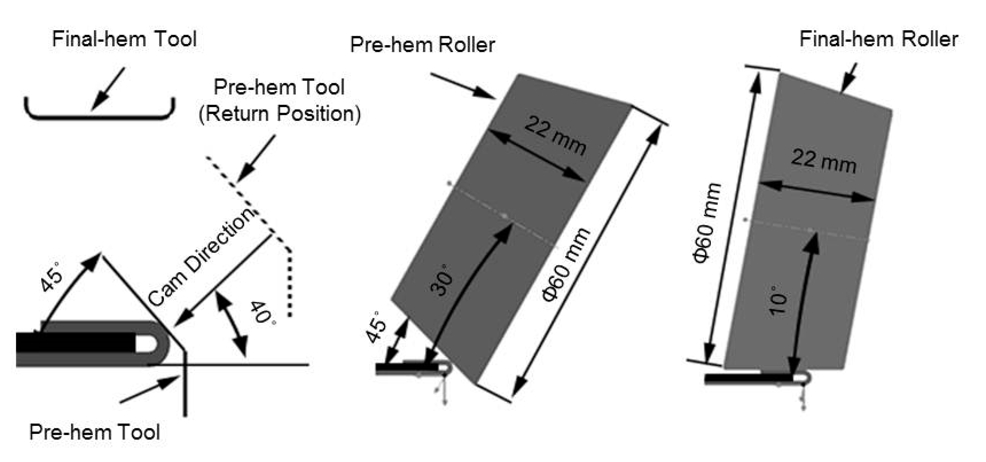
The test tools are shown in Figure 7. The flanging and die hemming tests were performed on a universal hydropress with nominal force of 1600 kN. The upper pad force of flanging operation was supplied by two gas springs of 5 kN, and the outer and inner part in the die hemming were clamped through a pad supported by two same gauge gas springs (see Figure 7a,b). The pre-hemming and final hemming of the die hemming operation were accomplished via single stroke of the press, wherein, a Cam driver (Sankyo Oilless, Tianjin, China) device was used to implement the 45° pre-hemming. The roller hemming test was carried out on a specialized working table and three mechanical clamps were used to clamp the outer and the inner part (Figure 7c). For the roller hemming test, the 15° positive taper roller (pre-hem roller) and the 10° negative taper roller (final-hem roller) were used respectively in the pre-hemming and final hemming step (Figure 7d), and this angular design is helpful for optimizing the robot’s movement trajectory and avoiding collisions in practical production (Figure 10). The hemming rollers mounted on the KUKA KR 1000 Titan 6-Dof robot (KUKA, Shanghai, China) were used to progressively bend the outer flanging, as shown in Figure 7d.

2.3. Numerical Simulation

The numerical simulations were used to predict the fracture in die hemming and roller hemming. A commercial sheet metal forming finite element software, Autoform_R7 (R7, Autoform, Shanghai, China), was utilized to simulate these processes. First, the original blank was biaxially stretched in simulation to obtain the same stress-strain state as the experiments (see Figure 8). Subsequently, the pre-stretched blank, which contained 5% pre-stretching along the hemline direction and 12% pre-stretching perpendicular to the hemline, was trimmed back to the size of 300 mm × 200 mm. The final blank after trimming was used to simulate the flanging and hemming process.
Flanging process was carried out using three tools, namely a lower punch whose flanging radius (Rf) was used as the research variables, an upper pad with 10 kN blank holder force, and a flanging die with a radius of 2 mm. The die hemming and roller hemming process were simulated after the flanging operation. The die hemming was established with pre-hemming and final hemming, where the cam angle of pre-hemming step was 40°. The same hem procedures were applied in the roller hemming process, in which a 15° positive taper roller (pre-hem roller) and a 10° negative taper roller (final-hem roller) with the same geometric parameters as the experimental rollers were used in the pre-hemming and final hemming step, respectively. The model geometry is clearly shown in Figure 9. The trajectory parameters of the hemming tools are presented in Figure 10. The inner part was modelled as a rigid body as its deformation during the hemming process has a little effect on fracture.
The elastic-plastic shell element type with eleven integration points (EPS-11) was used to simulate the nonlinear properties during the forming process. The maximum side length of tools was 10 mm while the meshing tolerance was 0.03 mm. The initial maximum element size of blank was 10 mm and the maximum refinement level was 7. The penetration radius was 0.16 mm and the maximum element angle between the two adjacent elements was 20°. These meshing parameter settings have proved to meet the simulation precision [11]. The friction coefficient was set as a constant value of 0.14.
The hardening curve of 6014-T4 sheet was defined by the tensile test data in the small strain interval (logarithmic strain: 0–0.2) and the Swift/Hockett–Sherby model in the large strain range (logarithmic strain > 0.2). The fitting factor between Swift and Hockett–Sherby formula was 0.75, this is the default value in Autoform. The Banabic BBC2005 function was used to create yield criterion, which is defined using the three r-values and the three initial yield stresses as the minimum variant. The initial yield stress in the biaxial point σb and the r-value in the biaxial point rb were from Barlat function.
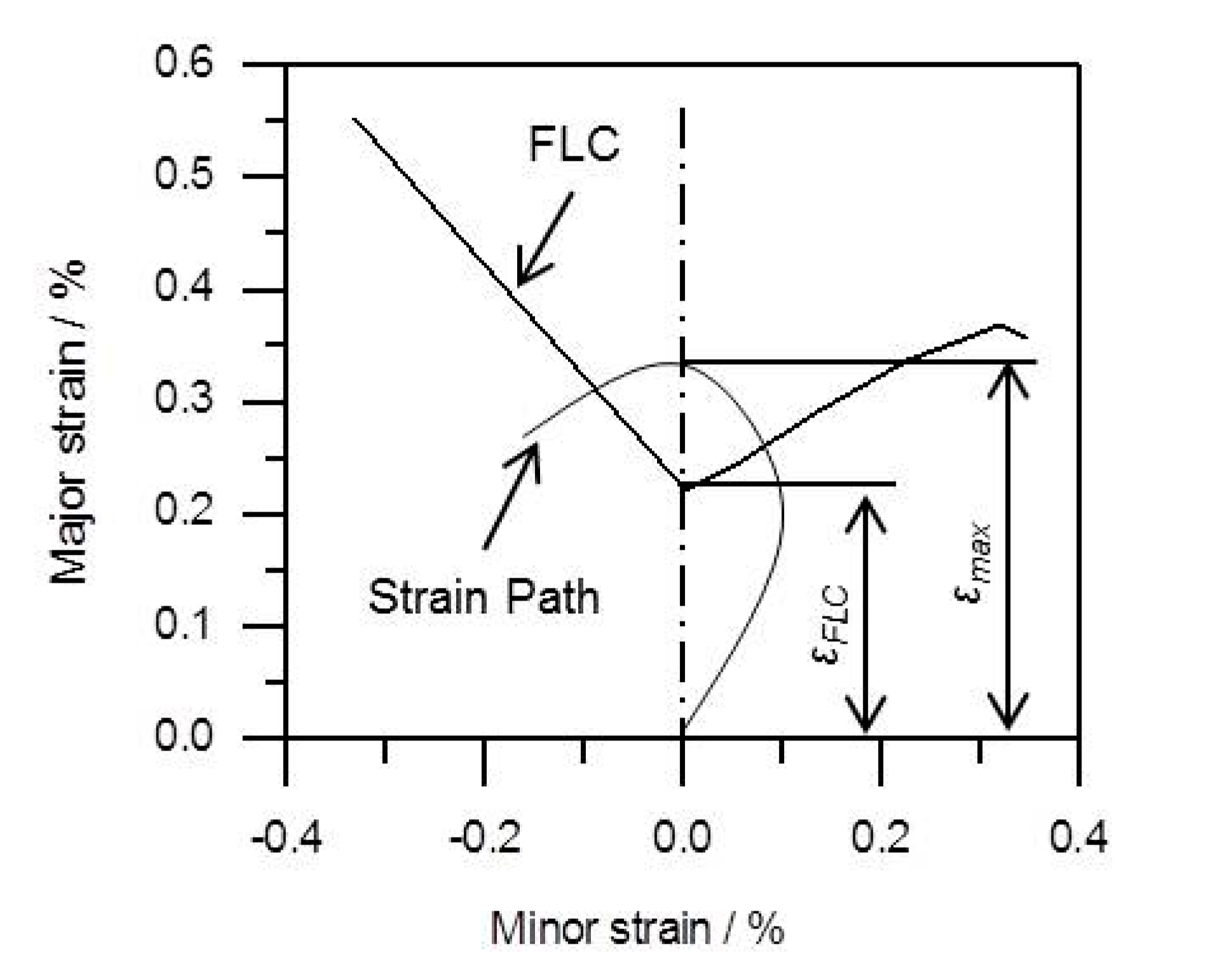
In this study, the maximum deformation zone of 6014-T4 sheet has undergone multiple processes, so its fracture behavior is significantly dependent on the strain path. Hence, the Max Failure evaluation criterion was adopted to assess fracture, as shown in Figure 11. The result variable Max Failure (Fm) is defined as the ratio between the maximum major strain computed at an element (εmax) during the whole forming process and the major strain of the strain based Forming Limit Curve (εFLC) for the same minor strain. This criterion assumes fracture happens when:
F m = ε m a x ε F L C 1

3. Results and Discussion

3.1. Natural Aging Characteristics

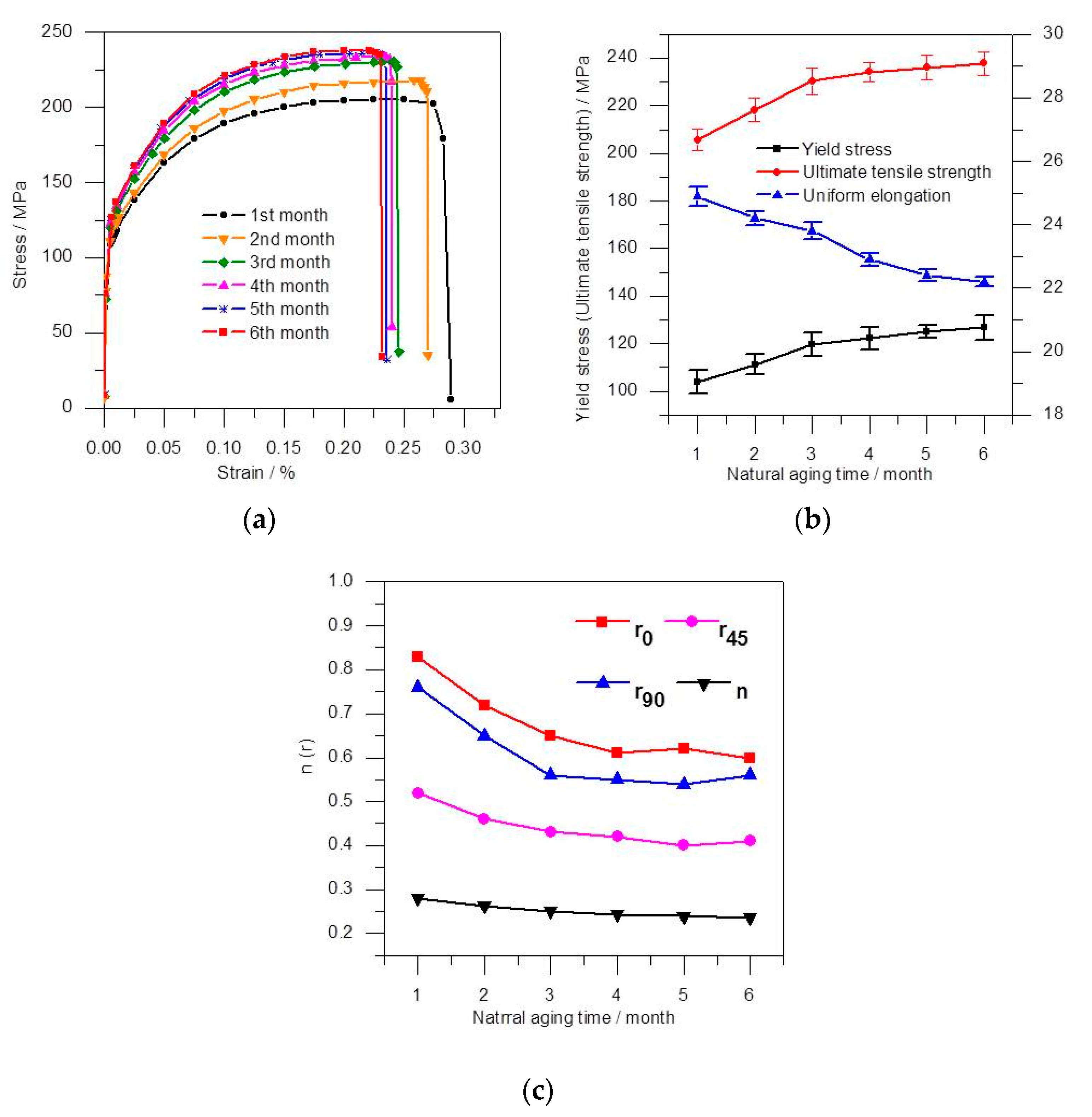
Figure 12 shows the development tendency of mechanical properties for 6014-T4 during natural aging. The monthly stress-strain curves of the tested specimens parallel to the rolling direction are presented in Figure 12a, clearly showing that the stress displayed an upward trend under the same strain as the natural aging continued, while the strain value of necking point generally declined, which indicated that the plasticity of 6014-T4 was getting worse due to natural aging. As shown in Figure 12b, the yield stress and ultimate tensile strength increased by an average of 23.1 MPa and 32.4 MPa, respectively, and the uniform elongation declined continuously from 24.9% to 22.2% for six months since the solution treatment, with the largest change in the first three months and then gradual stabilization thereafter. Similar variations in hardness have also been found in the natural aging process of Al-Mg-Si and Al-Mg-Si-Cu alloys with and without Zn addition [12,13]. The n-value and r-value (Figure 12c) clearly presented the opposite trend compared with the strength parameters. The r0, r45, and r90 at each time point differed, which means that the 6014-T4 sheet partly exhibits anisotropic behavior.
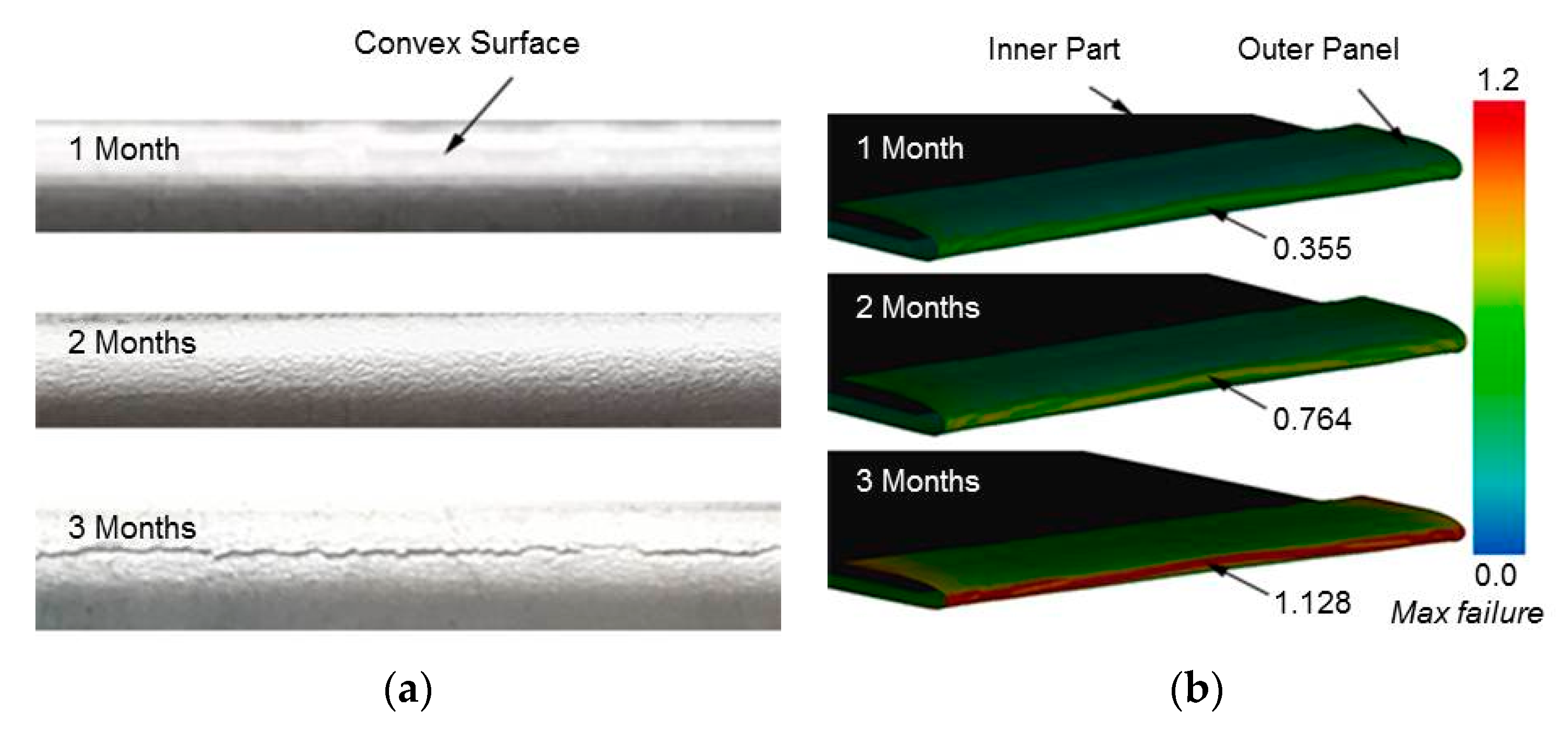
The macroscopic analysis results demonstrated above show that the 6014-T4 aluminum alloy sheet exhibits a significant natural aging tendency after the solution treatment. This phenomenon is primarily reflected in the increase of strength and the decrease of plasticity and toughness due to the precipitation, which increase the resistance of the dislocation motion [14]. Therefore, the formability of 6014-T4 aluminum alloy sheet would gradually deteriorate during the natural aging. Figure 13 shows the numerical and experimental results for formability in die hemming process with a Rf of 1.2 mm. Clearly, there was no fracture on the convex surface of the outer panel at the time point of the first and second month, but some heavy rough surface in the second month. The part hemmed after natural aging for 3 months showed an obvious fracture on its convex surface. The simulation results agree extremely well with the experimental ones, which basically proved the applicability of the proposed finite element model and the corresponding selected evaluation criterion.

3.2. Flanging Radius

Note that the previous discussion has uncovered that the fluctuation of the material properties inclined to be stable after natural aging for 3 months. Thus, the experimental parameters of tensile tests in the third month were used to simulate the flanging and hemming process. Table 2 shows the mechanical parameters, E is the Young’s modulus, ν is the Poisson ratio, σ0 is the yield stress, and Rm is the ultimate tensile strength.
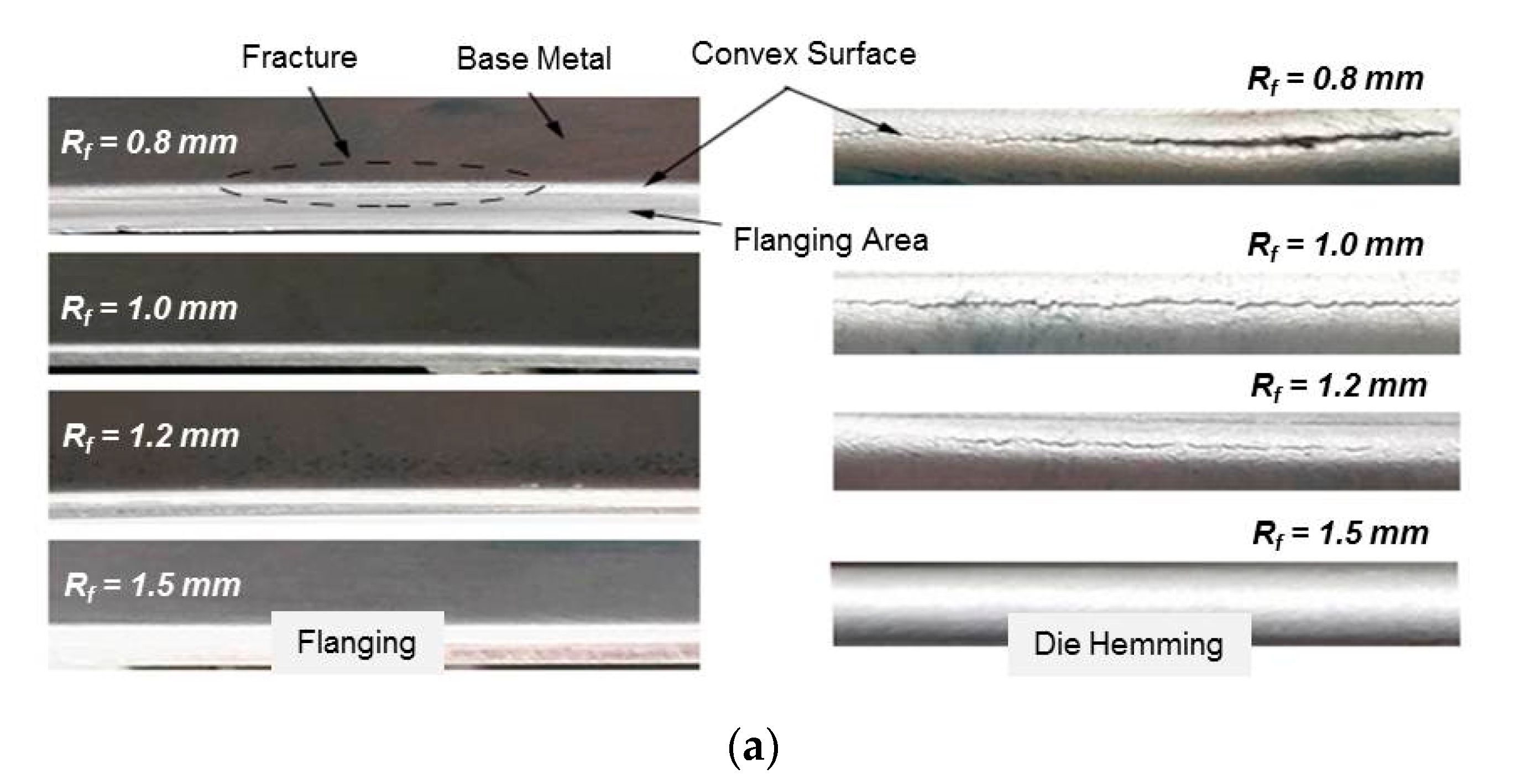
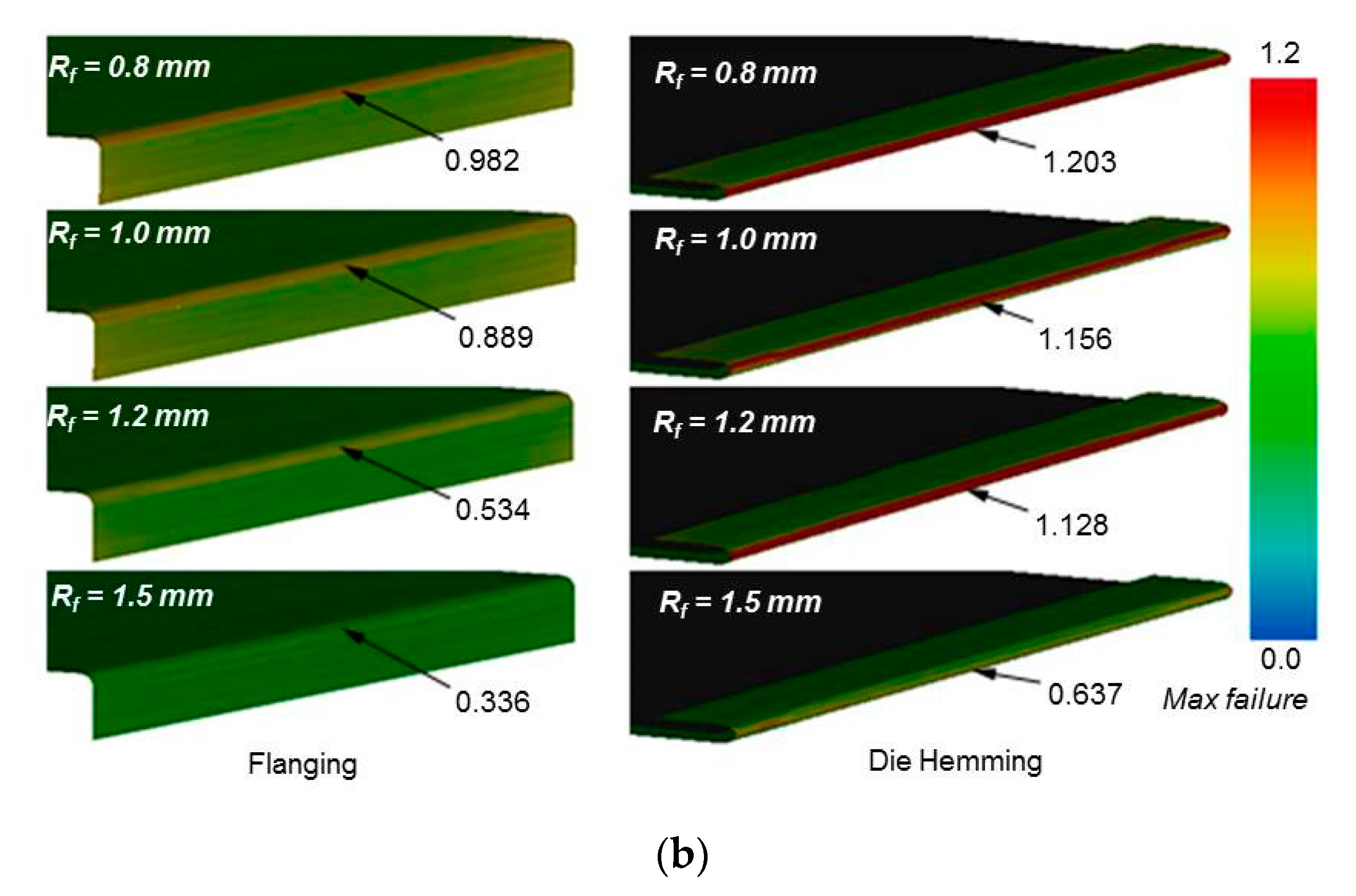
For a complete hemming process, the deformation of the outer panel started accumulating from the flanging operation. Figure 14 illustrates the influence of the Rf on the fracture in the flanging and die hemming process. When the Rf was less than or equal to 1 mm, fracture or potential fracture initially appeared on the convex surface after flanging, which worsened after hemming. When the Rf was equal to 1.2 mm, a flanged part without the fracture was obtained then the fracture occurred after the hemming process. Clearly, the hemmed part with the Rf of 1.5 mm showed a favorable formability in simulation and experiment.
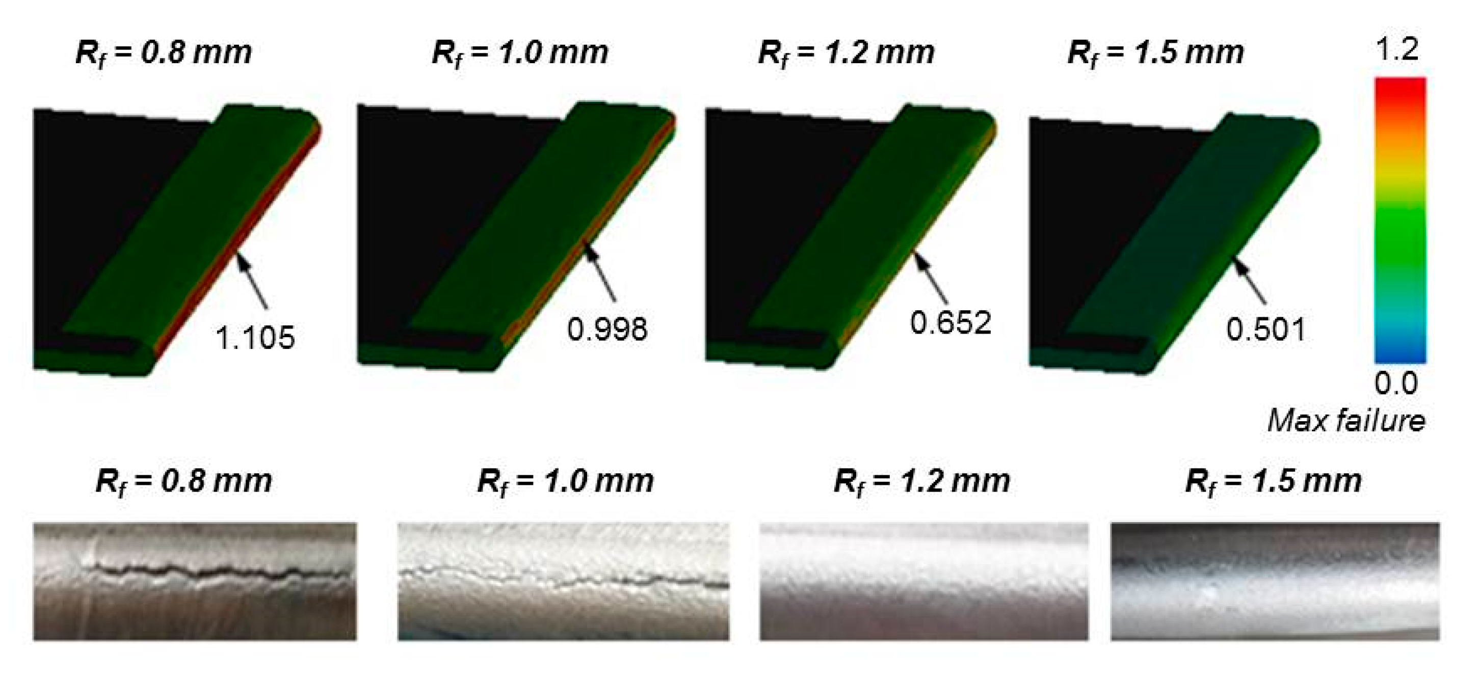
The effect of Rf on fracture in the roller hemming process is shown in Figure 15. Both experimental and simulation results demonstrate that serious fracture happened when the Rf was less than 1.2 mm. Table 3 shows the formability results in detail. Therefore, the Rf can be designed as 1.2 mm to fully produce well-formed hemming assembly in the roller hemming process. This finding is different from the result issued by Hu et al. [15], whose work showed a fracture based on Cockcroft–Latham criterion, the material was 6061-T6 with a thickness of 1 mm and the Rf was 2 mm. Perhaps this discrepancy in formability is related to the properties of the selected materials, which need further verification for the tooling die design of aluminum alloy sheet.
It should be noted that the no necking zone was captured in this study, so it is insufficient to verify the consistency between simulation and experiment under the critical strain state. On the other hand, all cracks along the hemming line or flanging line were discontinuous in the experiments, while the distribution of evaluation indicators was very uniform in the simulation. This difference indicates that the Max failure criteria derived from FLC needs further correction. A localization level forming limit diagram (LL-FLD) based on the fracture region micro-measurement method (thinning method) has been shown to be more suitable criteria for failure prediction on forming processes with small bending radii [16,17]. In addition, because shell element was used, the Max failure values in the simulation were calculated based on the strain state of the neutral layer of sheet metal. However, given the strain gradient over the thickness, the Max failure on the convex surface must be larger than that in the neutral layer, and it can be inferred that the strain state on the convex surface should also exceed the LL-FLD in the fracture regions. Hence, the comparison between simulation and experiment only indicated that the fracture occurred when the Max failure value was greater than 1, while more accurate evaluation criteria for 6014-T4 based on LL-FLD need to be further researched.

3.3. Hemming Process Comparison

When the Rf was 1.2 mm, the roller hemming process exhibited better formability as compared to the die hemming process.
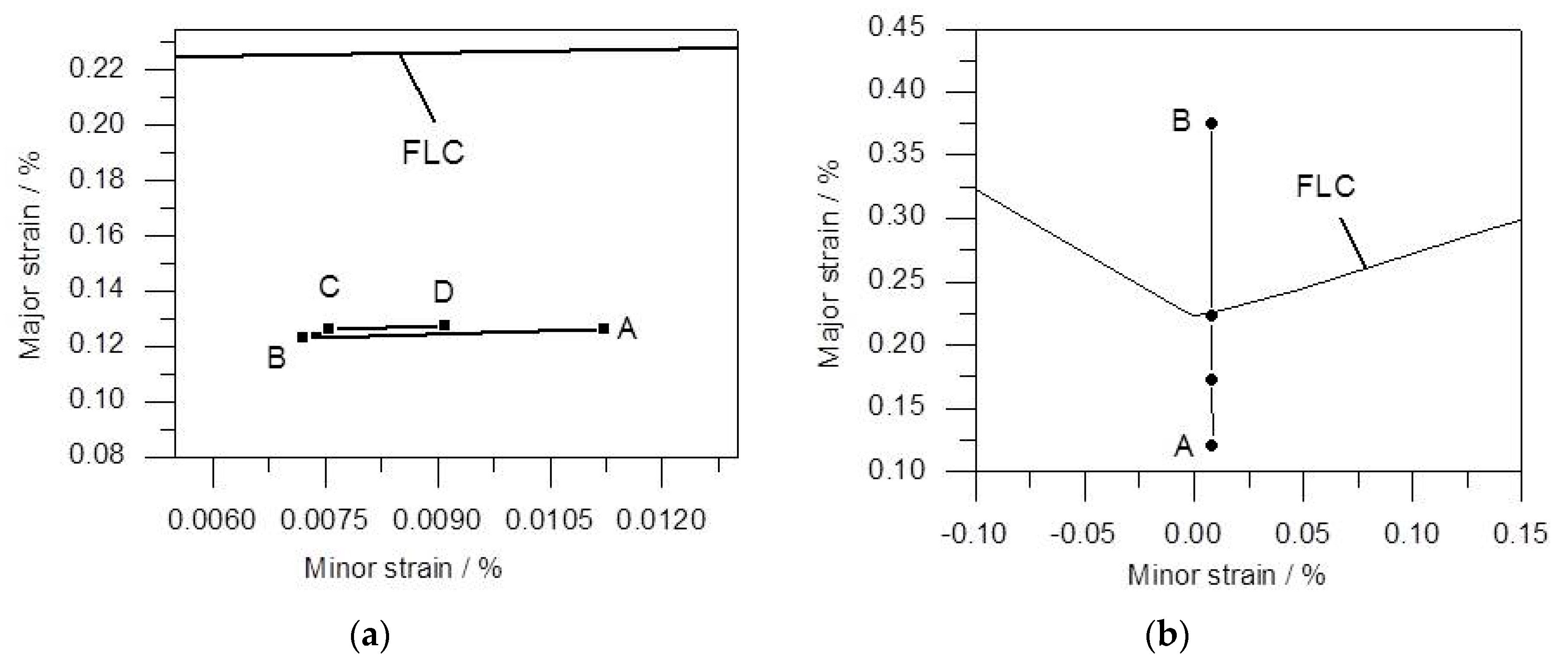
To compare the deformation process, an intermediate node was selected to establish the strain path curve to eliminate the effect of the free edge. In the roller hemming process, the flanged surface was folded orderly over the inner part along the hemline. As the pre-hem roller approached the selected node, the flanged surface as well as the adjacent convex surface on which the node was located became compressed in the hemline direction and the section perpendicular to the hemline. As a result, both the major strain and minor strain were reduced (Figure 16a) and the strain path moved from A to B. Thereafter, the pre-hem roller moved forward through the node and as the convex surface was under tension strain, the strain path went up from B to C. When the final-hem roller was passed, the tension strain increased further to D point. In the die hemming process, the flanged surface was hemmed simultaneously, which resulted in a linear increase in the major strain while the minor strain was almost constant (Figure 16b).

4. Conclusions

The yield stress and ultimate tensile strength of 6014-T4 sheet continuously increased while the Ag, n-value, and r-value decreased during the natural aging period. The largest change was in the first three months after the solution treatment and thereafter, there was a gradual stabilization. This variation tendency is adverse for formability. The mechanical parameters at the time point of the third month after solution treatment were recommended to simulate the formability of 6014-T4 sheet in the forming and hemming production.
In view of the hemming fracture, the Rf is recommended as a 1.5 mm design in the die hemming process, while this value is at least 1.2 mm in the roller hemming process. The proposed finite element model can be well used to evaluate fracture in the die design stage.
The roller hemming process tended to produce better formability as compared to the die hemming process.

5. Limitation

The age hardening of 6014-T4 aluminum sheet is closely related to the precipitation, which needs to be analyzed by precise methods, such as transmission electron microscopy, atom probe tomography, and differential scanning calorimetry. Considering the complexity of precipitation, only the mechanical properties of 6014-T4 were researched in this study, while the metallographic study of the structure is one of our future research directions. Moreover, in order to obtain a better correspondence between simulation and experiment, more accurate evaluation criteria need to be adopted, such as the LL-FLD criteria proposed by Gorji et al. [16,17], and the grain gradient over the thickness must be considered.

Author Contributions

Supervision, Z.G.; Software, experiment and writing, G.W.; Analysis, G.Y. All authors have read and agreed to the published version of the manuscript.

Funding

This study was funded by the National Nature Science Foundation of China (No. 51101072) and Technology Development Program of Jilin Province (No. 20160204058GX).

Acknowledgments

The authors are grateful to FAW Tooling Die Manufacturing Co., Ltd. for their valuable help in the experimental part.

Conflicts of Interest

The authors declare that they have no conflict of interest.

References

  1. Muderrisoglu, A.; Murata, M.; Ahmetoglu, M.A.; Kinzel, G.; Altan, T. Bending, flanging, and hemming of aluminum sheet—An experimental study. J. Mater. Process. Technol. 1996, 59, 10–17. [Google Scholar] [CrossRef]
  2. Tisza, M.; Czinege, I. Comparative study of the application of steels and aluminium in lightweight production of automotive parts. Int. J. Light. Mater. Manuf. 2018, 1, 229–238. [Google Scholar] [CrossRef]
  3. Carleer, B. Effective Stamping Simulations along the Sheet Metal Process Chain. J. Physics: Conf. Ser. 2018, 1063, 012001. [Google Scholar] [CrossRef]
  4. Thuillier, S.; Le Maoût, N.; Manach, P.Y. Bending Limit Prediction of an Aluminum Thin Sheet. Int. J. Mater. Form. 2010, 3, 223–226. [Google Scholar] [CrossRef]
  5. Pradeau, A.; Thuillier, S.; Yoon, J.W. Prediction of failure in bending of an aluminium sheet alloy. Int. J. Mech. Sci. 2016, 119, 23–35. [Google Scholar] [CrossRef]
  6. Li, S.; Hu, X.; Zhao, Y.; Lin, Z.; Xu, N. Cyclic hardening behavior of roller hemming in the case of aluminum alloy sheets. Mater. Des. 2011, 32, 2308–2316. [Google Scholar] [CrossRef]
  7. Liewald, M.; Hönle, S.; Sindel, M. Surface roughening of an aluminum 6016 alloy during bending and hemming. Int. J. Mater. Form. 2016, 9, 203–213. [Google Scholar] [CrossRef]
  8. Muhammad, W.; Kang, J.; Brahme, A.P.; Ali, U.; Hirsch, J.; Brinkman, H.-J.; Engler, O.; Mishra, R.K.; Inal, K. Bendability enhancement of an age-hardenable aluminum alloy: Part I—Relationship between microstructure, plastic deformation and fracture. Mater. Sci. Eng. A 2019, 753, 179–191. [Google Scholar] [CrossRef]
  9. Engler, O.; Schäfer, C.; Myhr, O.R. Effect of natural ageing and pre-straining on strength and anisotropy in aluminium alloy AA 6016. Mater. Sci. Eng. A 2015, 639, 65–74. [Google Scholar] [CrossRef]
  10. Engler, O.; Marioara, C.; Aruga, Y.; Kozuka, M.; Myhr, O. Effect of natural ageing or pre-ageing on the evolution of precipitate structure and strength during age hardening of Al–Mg–Si alloy AA 6016. Mater. Sci. Eng. A 2019, 759, 520–529. [Google Scholar] [CrossRef]
  11. Wang, G.; Gu, Z.; Xu, H.; Yu, G. Numerical analysis and experimental investigation of surface defects in die hemming process. Int. J. Mater. Form. 2019, 1–12. [Google Scholar] [CrossRef]
  12. Aruga, Y.; Kim, S.N.; Kozuka, M.; Kobayashi, E.; Sato, T. Effects of cluster characteristics on two-step aging behavior in Al-Mg-Si alloys with different Mg/Si ratios and natural aging periods. Mater. Sci. Eng. A Struct. 2019, 718, 371–376. [Google Scholar] [CrossRef]
  13. Zhu, S.; Li, Z.; Yan, L.; Li, X.; Huang, S.; Yan, H.; Zhang, Y.; Xiong, B. Natural aging behavior in pre-aged Al–Mg–Si–Cu alloys with and without Zn addition. J. Alloy. Compd. 2019, 773, 496–502. [Google Scholar] [CrossRef]
  14. Martinsen, F.; Ehlers, F.; Torsæter, M.; Holmestad, R. Reversal of the negative natural aging effect in Al–Mg–Si alloys. Acta Mater. 2012, 60, 6091–6101. [Google Scholar] [CrossRef] [Green Version]
  15. Hu, X.; Lin, Z.; Li, S.; Zhao, Y. Fracture limit prediction for roller hemming of aluminum alloy sheet. Mater. Des. 2010, 31, 1410–1416. [Google Scholar] [CrossRef]
  16. Gorji, M.; Berisha, B.; Hora, P.; Barlat, F. Modeling of localization and fracture phenomena in strain and stress space for sheet metal forming. Int. J. Mater. Form. 2016, 9, 573–584. [Google Scholar] [CrossRef]
  17. Gorji, M.; Berisha, B.; Manopulo, N.; Hora, P. Effect of through thickness strain distribution on shear fracture hazard and its mitigation by using multilayer aluminum sheets. J. Mater. Process. Technol. 2016, 232, 19–33. [Google Scholar] [CrossRef]
Figure 1. Steps in the hemming process: (a) flanging; (b) pre-hemming; and (c) final hemming.
Metals 10 00081 g001
Figure 2. The typical aluminum hemmed components in autobody, the dotted blue lines represent the hemmed edges. (a) Hood hemming assembly and (b) door hemming assembly.
Metals 10 00081 g002
Figure 3. Uniaxial tensile specimen.
Metals 10 00081 g003
Figure 4. Nakazima cup test specimens.
Metals 10 00081 g004
Figure 5. Cross stretching experiments.
Metals 10 00081 g005
Figure 6. Original blank size before biaxial stretching and trimming size after biaxial stretching.
Metals 10 00081 g006
Figure 7. Forming tools for tests: (a) flanging die; (b) hemming die; (c) roller hemming fixture; and (d) robot and rollers.
Metals 10 00081 g007aMetals 10 00081 g007b
Figure 8. Geometric model of biaxial stretching and trimming.
Metals 10 00081 g008
Figure 9. Geometric model of the forming operations: (a) flanging; (b) die hemming; and (c) roller hemming.
Metals 10 00081 g009
Figure 10. Trajectory parameters of the hemming tools.
Metals 10 00081 g010
Figure 11. The Max Failure evaluation criteria of 6014-T4 sheet.
Metals 10 00081 g011
Figure 12. Tensile test results for 6014-T4: (a) engineering stress–strain curve; (b) tendency graph of strength parameters; and (c) variation trend of n-value and r-value.
Metals 10 00081 g012
Figure 13. Experimental and numerical results for fracture in die hemming process with a Rf of 1.2 mm: (a) convex surface images of the outer panels and (b) Max failure indicator in simulation.
Metals 10 00081 g013
Figure 14. Experimental and simulation results based on different Rf in the flanging and die hemming process: (a) convex surface images of the outer panels and (b) Max failure indicator in simulation.
Metals 10 00081 g014aMetals 10 00081 g014b
Figure 15. Experimental and simulation results based on different Rf in the roller hemming process.
Metals 10 00081 g015
Figure 16. Strain path of the nodes located in the middle of convex surface: (a) roller hemming and (b) die hemming.
Metals 10 00081 g016
Table 1. Chemical composition of 6014-T4 aluminum alloy sheet (wt.%).
SiFeCuMnMgCrZnTiAl
0.590.220.120.080.650.010.010.03Bal.
Table 2. Mechanical properties of 6014-T4 in the third month after solution treatment.
E (GPa)νσ0 (MPa)Rm (MPa)nr0r45r90
700.3116225.40.2530.650.430.56
Table 3. Formability experimental results of 6014-T4.
ProcessFlanging Radius
0.8 mm1.0 mm1.2 mm1.5 mm
FlangingYYNN
Die hemmingYYYN
Roller hemmingYYNN
Y: fracture exist; N: no fracture.