Article

Establish Using FEM Method of Constitutive Model for Chip Formation in the Cutting Process of Gray Cast Iron

1
Modern textile equipment technology and Engineering research center of ministry of education, Zhejiang SCI-TECH University, Hangzhou 310018, China
2
College of Mechanical and Energy Engineering, Ningbo Institute of Technology, Zhejiang University, Ningbo 315100, China
*
Author to whom correspondence should be addressed.
Metals 2020, 10(1), 33; https://doi.org/10.3390/met10010033
Submission received: 21 November 2019 / Revised: 12 December 2019 / Accepted: 19 December 2019 / Published: 23 December 2019

Abstract

:
The constitutive equation of mechanics, namely the stress–strain model of the material, is used to describe the mathematical expression of the mechanical properties of the material (stress–strain–intensity–time relationship). In the cutting simulation of metals, the material constitutive model needs to be established. To study the cutting mechanism of gray cast iron using the finite element method (FEM), a series of split Hopkinson press bar (SHPB) tests are carried out to achieve the stress–strain curves of gray cast iron under different strain rates and temperatures. In the cutting simulation of gray cast iron, the Johnson–Cook (JC) constitutive equation is used to reflect the mechanical behavior during the cutting process. The calculation of JC constants is analyzed deeply and obtained from the SHPB test data. One orthogonal finite element model is developed with the JC material model to reveal the cutting mechanism of gray cast iron. The chip formation, stress distribution, temperature distribution, and cutting force are investigated through the cutting simulation. At the same time, cutting experiments of gray cast iron are carried out for validating the simulation results. The results of the cutting simulation and experiments show a good agreement.

1. Introduction

Cast iron is widely used in many industries due to its excellent properties, such as good casting performance, good vibration reduction, and good wear resistance [1,2]. Research concerning the cutting mechanism is helpful to the application of cast iron in industry. The cutting mechanism of metals is studied by considering the interaction between a workpiece and tool in the cutting process and various thermal-mechanical behaviors occurring in the cutting process, such as chip shape, cutting force, cutting temperature, residual stress, and tool wear. To investigate the cutting of cast iron, many scholars have worked to reveal the cutting mechanism of cast iron [3,4,5,6,7,8]. Yang and Li [3] investigated the formation mechanism of chips in the high-speed milling process of cast iron. Oliveira et al. [4] used the continuous and interrupted cutting with two grades of polycrystalline cubic boron nitride (PCBN) tools to analyze cutting performance during the turning process of white cast iron. Antônio et al. [5] adopted two surface milling tool systems in the high-speed milling process of gray cast iron. Martinez et al. [6] investigated the wear behavior of TiN and TiCN coated carbide tools during the face milling of pearlitic and ferritic ductile cast iron. Chen et al. [7] made an assessment of the abrasiveness of high chromium cast iron material on the wear performance of PCBN cutting tools during dry machining. Liu et al. [8] optimized the cutting parameters for reducing the power consumption in face milling of a cast iron alloy for environmental sustainability. All of the above studies used the experimental methods to study the cutting process of cast iron.
In recent years, the finite element method (FEM) has played a very important role in the investigation of the cutting process for metal materials. Many researchers have established finite element models to study the cutting process and these models include 2D and 3D models [9,10,11,12,13,14,15,16,17,18,19,20,21,22]. Xie et al. [9] used the finite element method to study the shear localization phenomena and chip formation in metal cutting process. Shih [10] established the orthogonal finite element model to reveal the formation of continuous chips in the cutting process of annealed low carbon steel. Wu and Zhang [11] investigated the effect of different cutting conditions on the milling of Ti6Al4V alloy by an orthogonal finite element model. Matsumura and Usui [12] established a finite element model based on the minimum cutting energy to predict the chip flow direction and milling force in the peripheral milling. Maurel-Pantel et al. [13] developed the 3D cutting model to perform the shoulder milling simulation of AISI 304L stainless steel by the software LS-Dynacopy. Ji et al. [14] simulated the helical milling hole process of Ti6Al4V alloy by a 3D finite element model with the damage initiation and evolution criterion. Mir et al. [15] presented a feasibility study of the potential application of the surface defect machining (SDM) method in the fabrication of silicon and similarly hard and brittle materials using a smooth particle hydrodynamics (SPH) simulation approach.
In the cutting simulation of metal materials, the constitutive model of materials is very critical for the production of accurate results [23,24,25,26]. The process of metal cutting is a thermal coupling process, including high strain and high temperature. Because the Johnson–Cook [JC] constitutive model [27] correlates the effect of temperature, stress, and strain rate on material properties, this model is widely employed in metal cutting simulation processes [28,29,30]. Daoud [28] investigated the influence of Johnson–Cook parameters on the chip morphology, cutting forces and contact length of tool-chip in simulation of Al2024-T3 alloy. Shrot and Bäker [29] used the Johnson–Cook constitutive model in cutting simulation of high-speed machining of AISI 52100. Wu and To [30] established the Johnson–Cook model of titanium alloy TC21 to analyze the adiabatic effect in the cutting process.
The Johnson–Cook constitutive model can be easily established from the experimental data achieved by the split Hopkinson press bar (SHPB) experiments with the different strain rate and temperature [31,32,33,34,35,36,37]. Wang et al. [31] used the SHPB test to investigate the dynamic mechanical behavior of alloy Inconel 718 under high temperature and strain rate in practical cutting process. Seo [32] investigated the influence of temperature on titanium alloy Ti6Al4V using high temperature SHPB experiment equipment. Zhong et al. [33] studied the ballistic properties and failure modes of the material based on the SHPB experiments. CJaspers and Dautzenberg [34] constructed a split Hopkinson pressure bar (SHPB) facility for obtaining the mechanical data at high temperatures and strain rate to determine the metal flow stress during cutting process.
The material constitutive model is the basis of finite element simulation of metal material cutting. The cutting process of metal materials includes high temperature, high strain rate. The constitutive experiments on metals need to be conducted over a wide range of temperature and strain rates so as to reflect accurately the thermal-mechanical behavior in cutting. In this paper, to investigate the mechanism in turning process of gray cast iron 200 using the finite element method, the JC constitutive model of gray cast iron for cutting simulation has been established by a high-temperature SHPB equipment. After establishing the JC material model, one orthogonal cutting model was presented to study the cutting process of gray cast iron using the software ABAQUS. The cutting phenomenon, including stress distribution, chip morphology, temperature distribution and cutting force have been obtained by simulation. Also, the cutting experiments of gray cast iron have been carried out to verify the results of cutting simulation. In addition, the cutting mechanism of gray cast iron has been revealed well through the research.

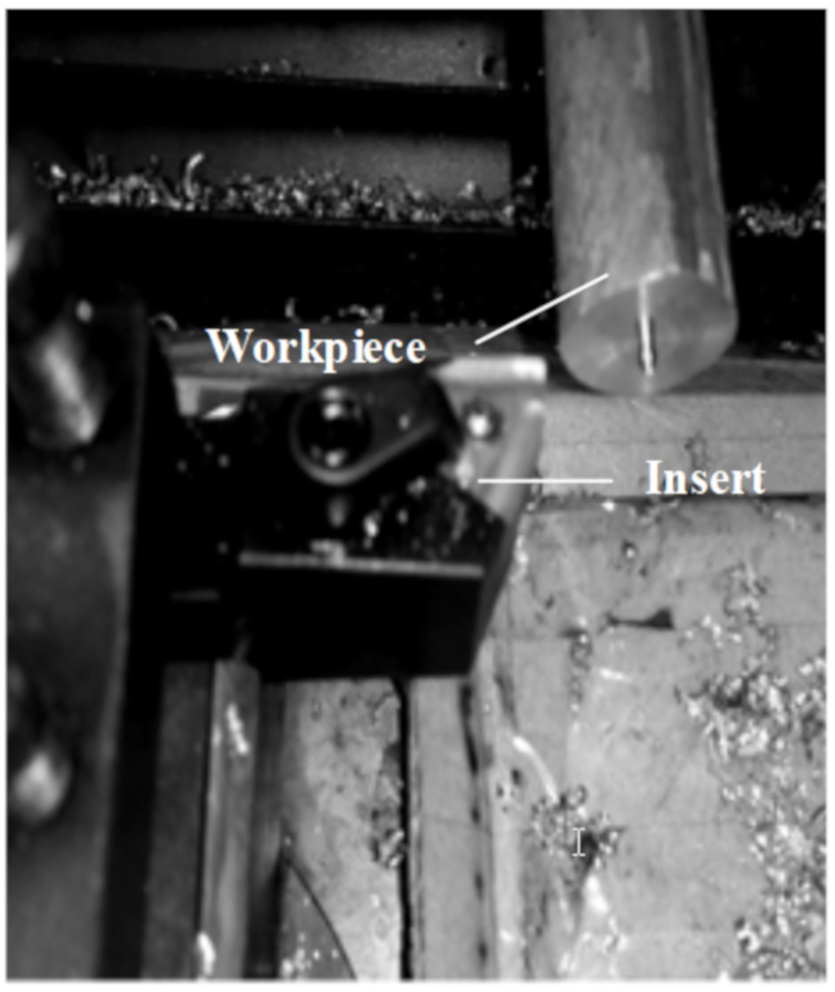
2. Experimental Setup

In this paper, the material type is the gray cast iron 200. As one of the most commonly used cast irons, the strength, plasticity and toughness of gray cast iron are lower than other cast irons. But gray cast iron has high wear resistance, low notch sensitivity and special vibration damping. The X-ray photoelectron spectroscopy system (Kratos Analytical Ltd, Manchester, England) is adopted to analyze the chemical composition and the mass percentages of the chemical elements are listed in Table 1. The mechanical properties of gray cast iron are listed in Table 2.
As one of the most important and reliable experimental methods, the split Hopkinson press bar is often used to study the dynamic mechanical behavior of various solid materials under high temperatures and strain rates. The schematic of the high temperature SHPB experiment is shown in Figure 1.
In the SHPB test process, the one-dimensional stress wave theory can be used to describe the loading process [38]. The loading process in SHPB can be described by the following equation.
ε s = 2 C 0 l s 0 t ε R d t
ε ˙ = d ε d t = 2 C 0 l S ε R
σ s = F 1 + F 2 2 A s = 1 2 E ( A A s ) ( ε I + ε R + ε T ) = E ( A A s ) ε T
where ε I , ε R and ε T are the signal of incidence, reflectance, and transmit bar obtained by the strain gages respectively, A s is the area of the sample cross section, L is the length of the sample, while A and E are the area of cross section and elastic modulus of the press bar.
To obtain the dynamic mechanical properties of gray cast iron, the SHPB experiments need to be performed under a series of temperatures and strain rates. In this paper, high-speed press experiments of gray cast iron are carried out by a modified SHPB system. In this modified SHPB system, one heated system was added to the SHPB apparatus, which can avoid the problem of overheating the incident bar and improve the experimental accuracy under high temperature conditions. During the SHPB test process, all samples of gray cast iron are fixed between the incident bar and transmit bar. Then, the samples will be heated to different temperatures by the heater furnace and pressed under the different speeds. The cylindrical rod of gray cast iron will be cut into many samples by electrical discharge wire cutting. The dimension of samples and the high temperature SHPB equipment used in this research are shown in Figure 2.
The detailed parameters of SHPB experiments for gray cast iron are temperature 20 °C, 200 °C, 400 °C and 600 °C, strain rate 500 S−1, 1000 S−1, 3000 S−1 and 5000 S−1. To investigate the cutting of gray cast iron a numerical control lathe machine ETC3650 (Shenyang Machine Tool Co Ltd, Shenyang, China) was used. The TiN-coated carbide inserts were used in the cutting tests. The rake angle and clearance angle of inserts are 0°, 13°. The tool edge radius is 0.015 mm. The diameter of cast iron rod is 20 mm. The cutting experiment setup is shown in Figure 3. The cutting parameters are listed in Table 3. The cutting experiment was carried out 5 times under the same cutting parameters. A Kistler 9255B dynamometer (Kistler Instrumente AG Co Ltd, Winterthur, Switzerland) was adopted to acquire the cutting force.

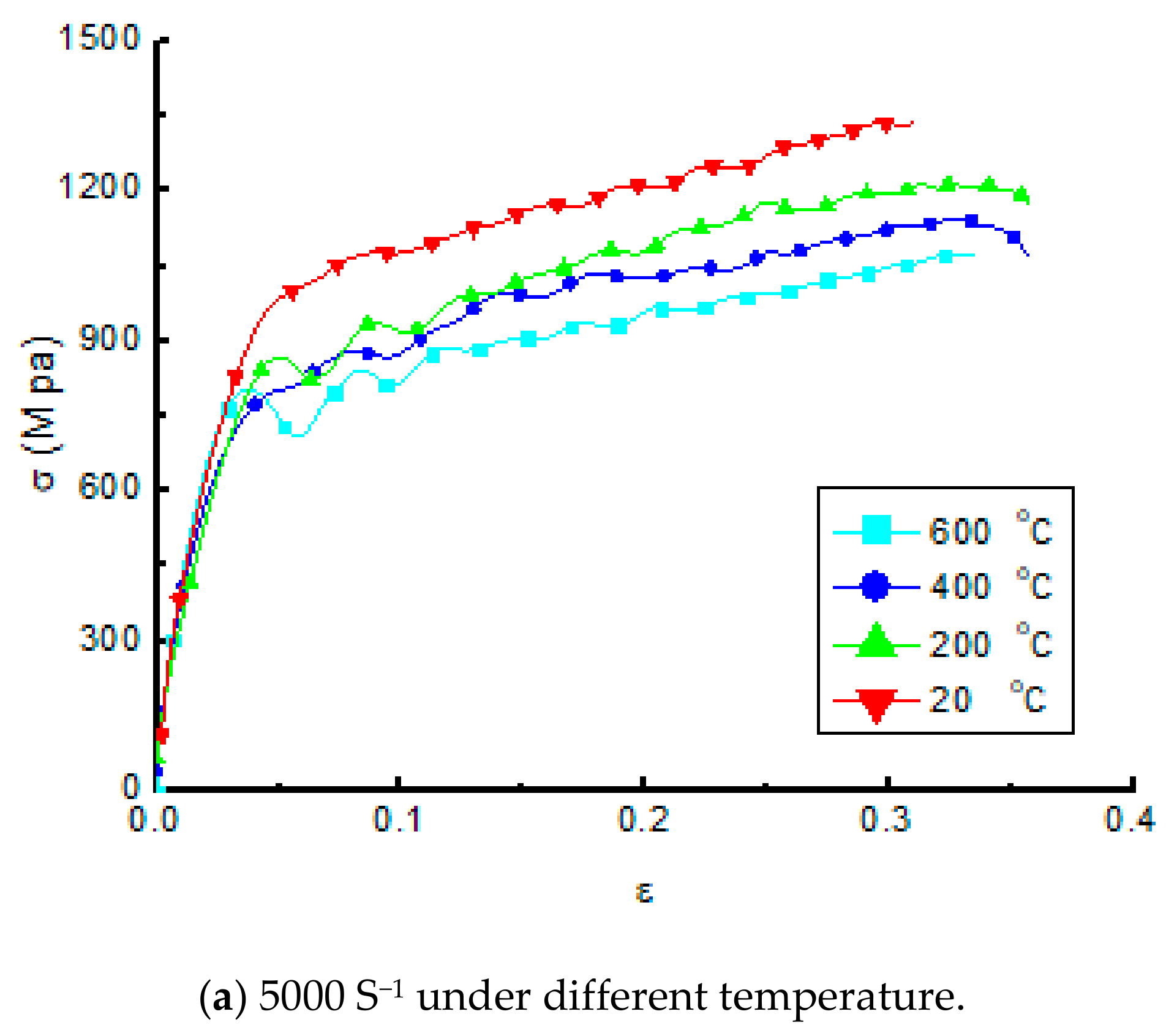
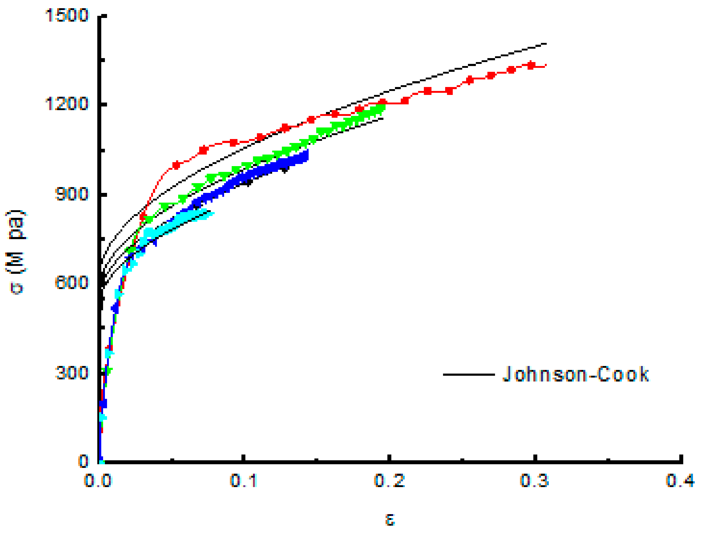
3. Establishment of Material Model

The stress–strain curves obtained by the SHPB tests are shown in Figure 4. Figure 4a shows the curves with strain rate 5000 S−1 under the different temperatures, and Figure 4b the curves at 600 °C under the different strain rates. Figure 4a confirms that the strength of gray cast iron decreased with the increasing of the temperature. Figure 4b shows that the strength of cast iron increased with the increasing of the temperature. So, the material cast iron is sensitive to the temperature and strain rate. In addition, these curves confirmed that cast iron is brittle material because the samples in the SHPB test have no yield phenomenon.
The Johnson–Cook equation will be used to express the constitutive model of gray cast iron needed in the cutting simulation, which can reflect the dynamic mechanical behavior of gray cast iron under the large deformation, high strain rate, and temperature in the cutting. The Johnson–Cook equation is:
σ = ( A + B ε n ) ( 1 + C ln ε ˙ ε ˙ 0 ) [ 1 ( T T r T m T r ) m ]
where ε is the equivalent plastic strain, ε ˙ and ε ˙ 0 are the equivalent and reference plastic strain rates. T, Tm and Tr are the temperature in cutting zone, melting and room temperature, respectively, A, B, n, C and m are the material constants of JC constitutive equation, representing the yield strength, strain and strain rate sensitivity, the strain hardening coefficient and the thermal softening coefficient.
The parameters of the Johnson–Cook equation for gray cast iron were calculated from the data of SHPB experiments. For the JC constants of gray cast iron, the calculation process is as follows:
σ = A + B γ n
A is equal to the initial yield stress of the material at ε ˙ = 1 / s and T = T r , which can be read directly from the true stress–strain curve. B γ n is the description of the strengthening section of the stress–strain curve, and so as long as the collection point of the strengthening section is drawn on double logarithmic coordinate paper, B and n can be determined by the following equation:
ln σ = ln B + n ln γ
The above equation is a line with intercept ln B and slope n on the double-log paper, So n can be expressed:
n = d ( ln σ ) d ( ln γ ) = Δ ln σ Δ ln γ
This equation, σ = 1 + C ln γ ˙ * , can be directly plotted on the semi-logarithmic coordinate paper to represent a line with intercept 1 and slope C, and the strain rate sensitivity coefficient C can be expressed:
C = Δ σ / Δ ln γ ˙ *
For σ = 1 T * m , when T * > > 1 , σ = T * m , so
ln σ = m ln T *
This represents a line on a piece of even coordinate paper, so
m = Δ ln σ Δ ln T *
These parameters of gray cast iron are listed in Table 4. Figure 5 is the comparison of the stress–strain curves obtained by the experiment and Johnson–Cook equation at 600 °C. The results confirm that the Johnson–Cook model agree well with the experimental data.

4. Finite Element Models

4.1. Cutting Model

One orthogonal finite element model of gray cast iron in the cutting process was developed by the finite element software ABAQUS 6.13 (Welize-villacubrai, France). The established cutting model is shown in Figure 6. To obtain the thermomechanical behavior of gray cast iron in the cutting process, the analysis step is “Dynamic Temperature-displacement, Explicit” in the cutting simulation. The dimension of workpiece is 3 × 1.5 mm2. To improve the computational efficiency, the workpiece meshes in cutting layer have been refined and the other meshes are sparse. The number of workpiece elements is 32,800 and the element type is CPE4RT. The minimal element size is 10 × 12 nm2. The cutting condition is set to be dry cutting. The tool has 6248 elements and the tool has a rigid body. The tool rake angle is 0°, the clearance angle is 13°, and the edge radius is 0.05 mm. The cutting parameters in the simulation are similar to the experiments. The initial environment temperature was set to 20 °C.

4.2. Friction Model

Friction between workpiece and tool has the significant effect on the cutting process. It is very important to establish the model that reflects the friction between tool and workpiece in cutting process. There exist two regions in the contact surface of the tool and workpiece, namely the sliding region and the sticking region [39]. The sliding region obeys the Coulomb friction law. The shear stress is equal to the critical frictional stress in sticking region. The frictional schematic of the contact surface between the chip and tool is shown in Figure 7. The frictional coefficient between the tool and chip is set to 0.25 in the cutting simulation of gray cast iron.

4.3. Damage Model

In this paper, the Johnson–Cook damage criterion [40] was employed. The criterion is as follows:
ε f = [ D 1 + D 2 exp ( D 3 p q ) ] [ 1 + D 4 ln ( ε ε 0 ) ] ( 1 + D 5 )
In Equation (11), D1-D5 are the failure parameters, p is the hydrostatic pressure, q is the Mises stress, ε 0 is the reference strain rate, and ε is the failure strain. The constants of Johnson–Cook fracture criterion D1–D5 are 0.62, 0.14, −0.25, 0.011, and 2.3, respectively.

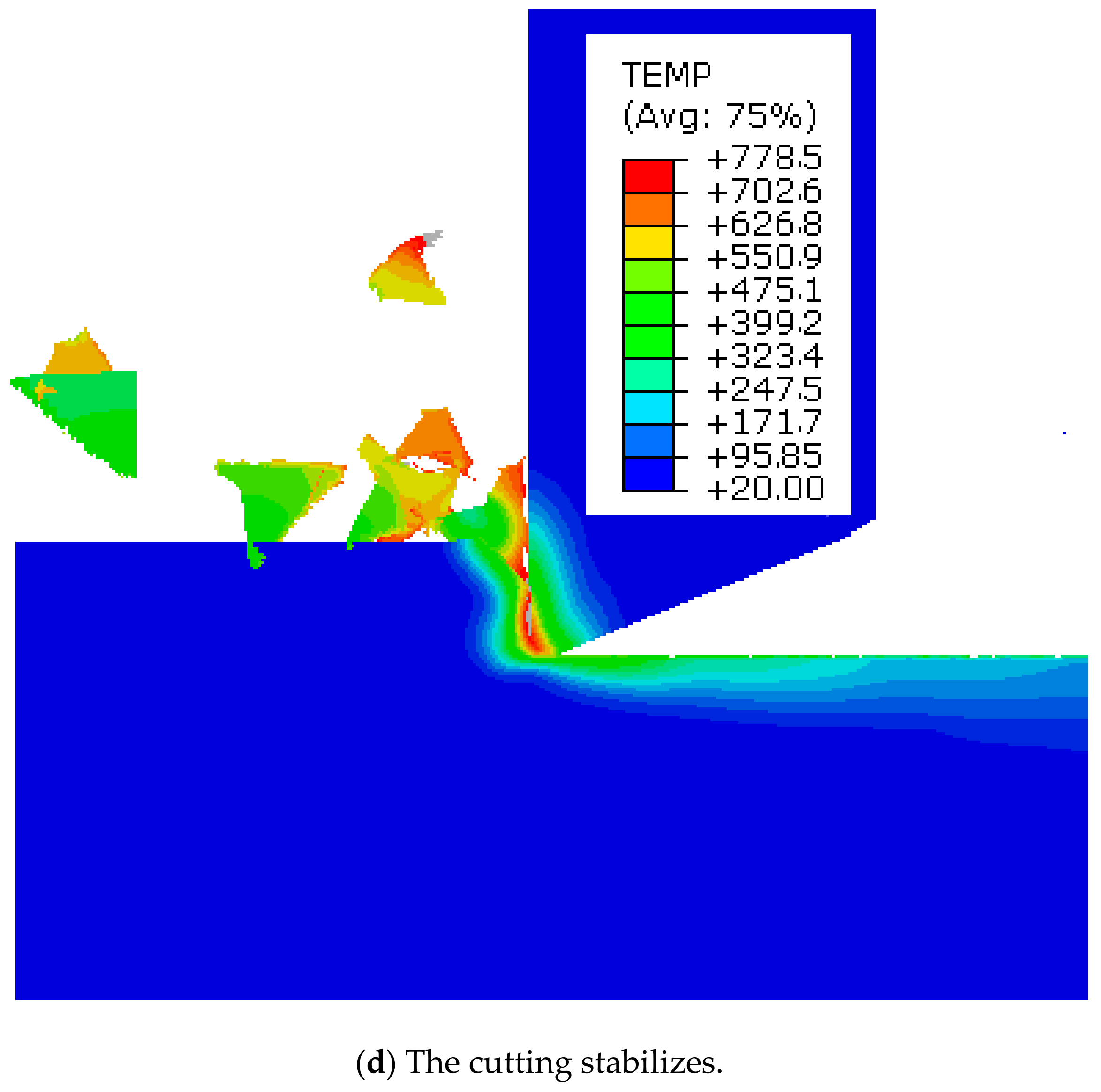
5. Results of Cutting Simulation

In metal cutting process, the chip will show a variety of different shapes due to the differences of workpiece material, tool geometry, cutting parameters, and other processing conditions. Figure 8 is the cutting process of gray cast iron obtained by the simulation. When the tool made contact with the workpiece, the stress of the shear band increased, and the crack occurred with the feeding of the tool, as shown in Figure 8a,b. As the crack grows rapidly, a block of chips is formed as shown in Figure 8c. When the cutting process is in a steady state, a lot of segmented chips formed and splashed out as shown in Figure 8d,e. The cutting simulation of cast iron confirmed that the chip is segmented because cast iron is a brittle material.
The energy consumed in the cutting process is mainly converted into cutting heat, which will cause the temperature of the tool and workpiece to rise. Cutting temperature has a direct impact on tool wear and life. Cutting heat can also change the mechanical properties and affect the generation and disappearance of chip nodules, which directly affects the cutting accuracy and cutting quality of the workpiece. Therefore, understanding the generation of cutting heat and the changing law of cutting temperature is important when studying the metal cutting process. Figure 9 shows the temperature distribution in the cutting process of gray cast iron under different states. The position of the highest temperature in the workpiece is located in the shear zone in contact with the tool tip, and the highest temperature area on the tool is also at the tool tip. Because the chip of gray cast iron is segmented, the contact length between the tool rake surface and chip is very short. The cutting force and cutting heat are concentrated near the cutting edge, which makes it easy to cause the tool to wear and damage.
Due to the difference of workpiece material, tool geometry and cutting parameters, and other processing conditions in the metal cutting, different deformation degree of materials will produce various forms of chips. The research of chip formation in the metal machining is very significant for the cutting mechanism of metals. Figure 10 is the photo of chip state obtained in the turning process of gray cast iron. The image demonstrates that the chip of cast iron is segmented.
Cutting force is the force that causes the material to deform and form chips when the cutter cuts into the workpiece. According to the main motion direction, cutting depth direction and feed direction, cutting force can be decomposed into three mutually perpendicular three components, the direction of cutting speed, the direction of cutting depth and the direction of feed speed. The primary cutting force is the component force in the direction of the cutting speed. Figure 11 is the comparison of the primary cutting force between cutting simulation and experiment of gray cast iron. It can be seen that the cutting force fluctuated wildly with the formation of the segmented chips. The fluctuation of the cutting force will decrease the surface quality and tool wear fast.

6. Conclusions

Metal cutting is a process that involves a high temperature, high strain, and high strain rate. The finite element method has been used to analyze the various cutting phenomena and the material constitutive model is needed in the cutting simulation. Aiming at the cutting of gray cast iron, to reflect the thermomechanical behavior in the cutting, a lot of SHPB compressive experiments at high temperature and strain rate were carried to investigate the dynamic mechanical properties of gray cast iron. The stress–strain relationship of gray cast iron under the different temperatures and strain rates were obtained through SHPB tests. At the same time, to reveal the cutting mechanism of gray cast iron, the Johnson–Cook constitutive model was established based on the SHPB tests. To ensure the accuracy of the simulation, the SHPB tests covered a series of strain rates and temperatures. An orthogonal cutting model with the JC material model was developed using the software ABAQUAS to simulate the cutting of gray cast iron. The chip formation, stress, cutting temperature, and cutting force have been achieved through the simulation. The results of the simulation and experiment show a good agreement with respect to chip formation and cutting force. The results of the simulation have been verified by the experiment.

Author Contributions

W.S. proposed the research method, and L.T. conducted the experiments and related research work. All authors have read and agreed to the published version of the manuscript.

Funding

This research received no external funding.

Conflicts of Interest

The authors declare no conflict of interest.

References

  1. Fallböhmer, P.; Rodríguez, C.A.; Özel, T.; Altan, T. High-speed machining of cast iron and alloy steels for die and mold manufacturing. J. Mater. Process. Technol. 2000, 98, 104–115. [Google Scholar] [CrossRef]
  2. Kato, H.; Shintani, K.; Sumiya, H. Cutting performance of a binder-less sintered cubic boron nitride tool in the high-speed milling of gray cast iron. J. Mater. Process. Technol. 2002, 127, 217–221. [Google Scholar] [CrossRef]
  3. Yang, Y.; Li, J.F. Study on mechanism of chip formation during high-speed milling of alloy cast iron. Int. J. Adv. Manuf. Technol. 2010, 46, 43–50. [Google Scholar] [CrossRef]
  4. Oliveira, A.J.D.; Boing, D.; Schroeter, R.B. Effect of PCBN tool grade and cutting type on hard turning of high-chromium white cast iron. Int. J. Adv. Manuf. Technol. 2016, 82, 797–807. [Google Scholar] [CrossRef]
  5. De Sales, A.M., Jr.; Sales, W.F.; Santos, S.C.; Machado, A.R. Performance of single Si3N4, and mixed Si3N4+PCBN wiper cutting tools applied to high speed face milling of cast iron. Int. J. Mach. Tools Manuf. 2005, 45, 335–344. [Google Scholar]
  6. Martinez, I.; Tanaka, R.; Yamane, Y.; Sekiya, K.; Yamada, K.; Ishihara, T.; Furuya, S. Wear characteristics of coated carbide tools in the face milling of ductile cast iron. Key Eng. Mater. 2017, 749, 178–184. [Google Scholar] [CrossRef]
  7. Chen, L.; Stahl, J.E.; Zhao, W.; Zhou, J. Assessment on abrasiveness of high chromium cast iron material on the wear performance of PCBN cutting tools in dry machining. J. Mater. Process. Technol. 2017, 255, 110–120. [Google Scholar] [CrossRef]
  8. Luan, X.; Zhang, S.; Cai, G. Optimal Cutting Parameters to Reduce Power Consumption in Face Milling of a Cast Iron Alloy for Environmental Sustainability. In Proceedings of the International Conference on Sustainable Design and Manufacturing, Heraklion, Greece, 4–6 April 2016; Volume 52, pp. 135–148. [Google Scholar]
  9. Xie, J.Q.; Bayoumi, A.E.; Zbib, H.M. FEA modeling and simulation of shear localized chip formation in metal cutting. Int. J. Mach. Tools Manuf. 1998, 38, 1067–1087. [Google Scholar] [CrossRef]
  10. Shih, A.J. Finite element analysis of the rake angle effects in orthogonal metal cutting. Int. J. Mech. Sci. 1995, 38, 1–17. [Google Scholar] [CrossRef]
  11. Wu, H.B.; Zhang, S.J. Effects of cutting conditions on the milling process of titanium alloy Ti6Al4V. Int. J. Adv. Manuf. Technol. 2015, 77, 2235–2240. [Google Scholar] [CrossRef]
  12. Matsumura, T.; Usui, E. Simulation of cutting process in peripheral milling by predictive cutting force model based on minimum cutting energy. Int. J. Mach. Tools Manuf. 2010, 50, 467–473. [Google Scholar] [CrossRef]
  13. Maurel-Pantel, A.; Fontaine, M.; Thibaud, S.; Gelin, J.C. 3D FEM simulations of shoulder milling operations on a 304L stainless steel. Simul. Model. Pract. Theory 2012, 22, 13–27. [Google Scholar] [CrossRef] [Green Version]
  14. Ji, C.; Li, Y.; Qin, X.; Zhao, Q.; Sun, D. 3D FEM simulation of helical milling hole process for titanium alloy Ti-6Al-4V. Int. J. Adv. Manuf. Technol. 2015, 81, 1733–1742. [Google Scholar] [CrossRef] [Green Version]
  15. Mir, A.; Luo, X.; Siddiq, A. Smooth particle hydrodynamics study of surface defect machining for diamond turning of silicon. Int. J. Adv. Manuf. Technol. 2017, 88, 2461–2476. [Google Scholar] [CrossRef] [Green Version]
  16. Wu, H.B.; Guo, L. Machinability of titanium alloy TC21 under orthogonal turning process. Mater. Manuf. Process. 2014, 29, 1441–1445. [Google Scholar] [CrossRef]
  17. Kilic, Z.M.; Altintas, Y. Generalized modelling of cutting tool geometries for unified process simulation. Int. J. Mach. Tools Manuf. 2016, 104, 14–25. [Google Scholar] [CrossRef]
  18. Jafarian, F.; Ciaran, M.I.; Umbrello, D.; Arrazola, P.L.; Filice, L. Finite element simulation of machining Inconel 718 alloy including microstructure changes. Int. J. Mech. Sci. 2014, 88, 110–121. [Google Scholar] [CrossRef]
  19. Komvopoulos, K.; Erpenbeck, S.A. Finite element modeling of orthogonal metal cutting. J. Eng. Ind. 1991, 113, 253. [Google Scholar] [CrossRef]
  20. Ceretti, E.; Lucchi, M.; Altan, T. FEM simulation of orthogonal cutting: Serrated chip formation. J. Mater. Process. Technol. 1999, 95, 17–26. [Google Scholar] [CrossRef]
  21. Özel, T.; Altan, T. Process simulation using finite element method—prediction of cutting forces, tool stresses and temperatures in high-speed flat end milling. Int. J. Mach. Tools Manuf. 2000, 40, 713–738. [Google Scholar] [CrossRef]
  22. Xiong, R.; Wu, H. Study on cutting mechanism of Ti6Al4V in ultra-precision machining. Int. J. Adv. Manuf. Technol. 2016, 86, 1–7. [Google Scholar]
  23. Paturi, U.M.R.; Narala, S.K.R.; Pundir, R.S. Constitutive flow stress formulation, model validation and FE cutting simulation for AA7075-T6 aluminum alloy. Mater. Sci. Eng. A 2014, 605, 176–185. [Google Scholar] [CrossRef]
  24. Boldyrev, I.S.; Shchurov, I.A.; Nikonov, A.V. Numerical simulation of the aluminum 6061-T6 cutting and the effect of the constitutive material model and failure criteria on cutting forces’ prediction. Procedia Eng. 2016, 150, 866–870. [Google Scholar] [CrossRef] [Green Version]
  25. Umbrello, D. Finite element simulation of conventional and high speed machining of Ti6Al4V alloy. J. Mater. Process. Technol. 2007, 196, 79–87. [Google Scholar] [CrossRef]
  26. Pantalé, O.; Bacaria, J.-L.; Dalverny, O.; Rakotomalala, R.; Caperaa, S. 2D and 3D numerical models of metal cutting with damage effects. Comput. Methods Appl. Mech. Eng. 2004, 193, 4383–4399. [Google Scholar] [CrossRef] [Green Version]
  27. Johnson, R.; Cook, W.K. A constitutive model and data for metals subjected to large strains high strain rates and high temperatures. In Proceedings of the 7th International Symposium on Balistics, The Hague, The Netherlands, 19–21 April 1983; pp. 541–547. [Google Scholar]
  28. Daoud, M.; Chatelain, J.F.; Bouzid, A. Effect of rake angle on Johnson-Cook material constants and their impact on cutting process parameters of Al2024-T3 alloy machining simulation. Int. J. Adv. Manuf. Technol. 2015, 81, 1987–1997. [Google Scholar] [CrossRef]
  29. Shrot, A.; Bäker, M. Is it possible to identify Johnson-Cook law parameters from machining simulations? Int. J. Mater. Form. 2010, 3, 443–446. [Google Scholar] [CrossRef]
  30. Wu, H.B.; To, S. Serrated chip formation and their adiabatic analysis by using the constitutive model of titanium alloy in high speed cutting. J. Alloy. Compd. 2015, 629, 368–373. [Google Scholar] [CrossRef]
  31. Wang, X.; Huang, C.; Zou, B.; Liu, H.; Zhu, H.; Wang, J. Dynamic behavior and a modified Johnson—Cook constitutive model of Inconel 718 at high strain rate and elevated temperature. Mater. Sci. Eng. A 2013, 580, 385–390. [Google Scholar] [CrossRef]
  32. Seo, S.; Min, O.; Yang, H. Constitutive equation for Ti–6Al–4V at high temperatures measured using the SHPB technique. Int. J. Impact Eng. 2005, 31, 735–754. [Google Scholar] [CrossRef]
  33. Zhong, W.Z.; Mbarek, I.A.; Rusinek, A.; Bernier, R.; Jankowiak, T. Development of an experimental set-up for dynamic force measurements during impact and perforation, coupling to numerical simulations. Int. J. Impact Eng. 2016, 91, 102–115. [Google Scholar] [CrossRef]
  34. Jaspers, S.P.F.C.; Dautzenberg, J.H. Material behaviour in conditions similar to metal cutting: flow stress in the primary shear zone. J. Mater. Process. Technol. 2002, 122, 322–330. [Google Scholar] [CrossRef]
  35. Dabboussi, W.; Nemes, J.A. Modeling of ductile fracture using the dynamic punch test. Int. J. Mech. Sci. 2005, 47, 1282–1299. [Google Scholar] [CrossRef]
  36. Zhou, T.; Wu, J.; Che, J.; Wang, Y.; Wang, X. Dynamic shear characteristics of titanium alloy Ti-6Al-4V at large strain rates by the split hopkinson pressure bar test. Int. J. Impact Eng. 2017, 109, 167–177. [Google Scholar] [CrossRef]
  37. Church, P.; Cornish, R.; Cullis, I.; Gould, P.; Lewtas, I. Using the split Hopkinson pressure bar to validate material models. Philos. Trans. R. Soc. A Math. Phys. Eng. Sci. 2014, 372, 20130294. [Google Scholar] [CrossRef] [PubMed]
  38. Fowles, R.; Williams, R.F. Plane stress wave propagation in solids. J. Appl. Phys. 1970, 41, 360–363. [Google Scholar] [CrossRef]
  39. Zorev, N.N. Inter-relationship between shear processes occurring along tool face and shear plane in metal cutting. Int. Res. Prod. Eng. 1963, 5, 42–49. [Google Scholar]
  40. Johnson, G.R.; Cook, W.H. Fracture characteristics of three metals subjected to various strains, strain rates, temperatures and pressures. Eng. Fract. Mech. 1985, 21, 31–48. [Google Scholar] [CrossRef]
Figure 1. Schematic of high temperature SHPB experiment.
Metals 10 00033 g001
Figure 2. Equipment of the SHPB test.
Metals 10 00033 g002
Figure 3. Turning experiments of gray cast iron.
Metals 10 00033 g003
Figure 4. Stress–strain curves of gray cast iron.
Metals 10 00033 g004aMetals 10 00033 g004b
Figure 5. Comparison of Johnson–Cook model and the experiment data at 600 °C.
Metals 10 00033 g005
Figure 6. Orthogonal finite element cutting model of gray cast iron.
Metals 10 00033 g006
Figure 7. Frictional schematic between tool and workpiece.
Metals 10 00033 g007
Figure 8. Stress and chip formation of cast iron.
Metals 10 00033 g008aMetals 10 00033 g008bMetals 10 00033 g008c
Figure 9. Temperature distribution in the cutting process of cast iron.
Metals 10 00033 g009aMetals 10 00033 g009bMetals 10 00033 g009c
Figure 10. Segmented chips of gray cast iron.
Metals 10 00033 g010
Figure 11. Comparison of primary cutting force between simulation and test.
Metals 10 00033 g011
Table 1. Mass percentages of various elements of gray cast iron.
CSiMnPSFe
3.52.10.80.010.095Others
Table 2. Mechanical properties of gray cast iron.
PropertiesValue
Hardness (HRC)43
Density (Kg/m3)7135
Elastic modulus (GPa)126
Heat conductivity (W/mk)39.2
Specific heat (J/kg·K)480
Table 3. Cutting parameters of cast iron.
ParametersValues
Depth of cut (mm)0.4
Spindle speed (r/min)3000
Feeding speed (mm/min)120
Cutting speed (m/min)188
Cutting environmentDry cutting
Table 4. Johnson–Cook parameters of gray cast iron.
A (Mpa)B (Mpa)nCm
4194050.20.0321.2

