Article

Experimental Investigation of the Influence of Wire Arc Additive Manufacturing on the Machinability of Titanium Parts

1
Department of Mechanical Engineering, University of the Basque Country (UPV/EHU), 48013 Bilbao, Spain
2
TECNALIA, Parque Científico y Tecnológico de Gipuzkoa, 20009 Donostia-San Sebastián, Spain
*
Author to whom correspondence should be addressed.
Metals 2020, 10(1), 24; https://doi.org/10.3390/met10010024
Submission received: 6 December 2019 / Revised: 19 December 2019 / Accepted: 20 December 2019 / Published: 22 December 2019
(This article belongs to the Special Issue Additive Manufacturing of Metals)

Abstract

:
The manufacturing of titanium airframe parts involves significant machining and low buy-to-fly ratios. Production costs could be greatly reduced by the combination of an additive manufacturing (AM) process followed by a finishing machining operation. Among the different AM alternatives, wire arc additive manufacturing (WAAM) offers deposition rates of kg/h and could be the key for the production of parts of several meters economically. In this study, the influence of the manufacturing process of Ti6Al4V alloy on both its material properties and machinability is investigated. First, the mechanical properties of a workpiece obtained by WAAM were compared to those in a conventional laminated plate. Then, drilling tests were carried out in both materials. The results showed that WAAM leads to a higher hardness than laminated Ti6Al4V and satisfies the requirements of the standard in terms of mechanical properties. As a consequence, higher cutting forces, shorter chips, and lower burr height were observed for the workpieces produced by AM. Furthermore, a metallographic analysis of the chip cross-sectional area also showed that a serrated chip formation is also present during drilling of Ti6Al4V produced by WAAM. The gathered information can be used to improve the competitiveness of the manufacturing of aircraft structures in terms of production time and cost.

1. Introduction

The additive manufacturing market (AM) applied to the aerospace sector has experienced a big increase in the last decade. According to the report carried out by Wohlers Associates, the worldwide revenue from AM related services reached 6 billion dollars in 2016 and the forecast is to get to 21 billion by 2020 [1]. In fact, the first titanium 3D-printed part of the Airbus A350 XWB entered serial production after the approval of the European Union Aviation Safety Agency (EASA) in late 2017.
The most extended AM technologies (such as laser melting deposition (LMD) and selective laser melting (SLM)) are based on the fusion a metallic powder using a laser or an electron beam as a heating source. These processes can reach good dimensional accuracy, but the part size is limited by the low deposition rate (0.12–0.6 kg/h) [2]. To produce airframe parts of several meters economically, deposition rates of kilograms per hour are needed and this can be obtained by wire arc additive manufacturing (WAAM) [3].
WAAM uses a solid wire as the feedstock material and an electric arc as the heat source. Several research works have dealt with the fundamental aspects of the process such as the final material microstructure and its mechanical properties [4,5,6,7]. In this regard, the review recently presented by Rodrigues et al. [8] provides an overview of the different process variants and the materials for WAAM. Moreover, it also deals with the effect of the post-processing treatments in the final mechanical properties as well as with non-destructive testing.
Among the different workpiece materials, titanium-based alloys are being increasingly tested in WAAM owing to their adoption by the aerospace industry for airframe manufacturing. For example, Ti alloys represent 15% of the weight of the Boeing 787 [9]. The microstructure and mechanical properties of Ti6Al4V alloy parts made by WAAM were investigated by Wang et al. [6]. Microstructural banding was observed, and it was related to the repeated thermal cycles that occur during the layer by layer growth of the workpiece. Regarding mechanical properties, the yield and ultimate tensile strengths were found to be lower in the WAAM part than in that produced by forging. However, similar ductility values were observed, and the mean fatigue life was significantly higher in the workpiece produced by WAAM. In a recent study, Ho et al. [4] investigated in great detail the microstructure banding found in this alloy using both multiscale compositional and automated image mapping tools. This approach provided evidence of weak micro-segregation during solidification and explained the origin of such microstructure.
The main disadvantages of WAAM, when compared with other AM processes, are the reduced dimensional accuracy and poor surface finish [10,11]. Therefore, a machining operation is mandatory to achieve the functional requirements. During the assembly of an airframe, for example, a large number of holes are machined, and the control of the drilling operation becomes crucial.
Drilling of titanium is one of the most complex processes in the production of aircraft structures. Ti alloys have been reported as difficult to cut materials owing to their particular physical properties [12,13,14]. On the one hand, their low thermal conductivity (about 15 W/m K versus 270 W/m K for the steel CRS1018 at 700 °C) [15] leads to high temperatures in the cutting zone. However, they maintain their high mechanical strength and abrasiveness at such temperatures, resulting in high forces and fast tool wear. On the other hand, the chemical affinity with tool materials leads to a fast titanium adhesion to the cutting tool. The resulting built up edge (BUE) or chipping of the cutting edges often lead to poor surface finish of the inner surface of the hole (and, in the worst scenario, to premature failure of the cutting tool) [13].
The selection of the most appropriate cutting parameters (feed and cutting speed) is of vital importance for the success of the process. Previous studies have thoroughly analysed the effect of cutting parameter variation in the cutting forces and the resulting hole quality. Sharif et al. [14], for example, evaluated the performance of both uncoated and coated tungsten carbide drills at various cutting speeds. They observed that the average surface roughness value (Ra) decreased by approximately 20% by doubling the cutting speed. They also reported that uncoated drills are not suitable for cutting speeds over 25 m/min owing to their fast wear. In another study, Le Coz et al. [12] carried out a comprehensive study to test the effect of the variation of both the feed and cutting speed in the cutting forces. They observed an increase of a 60% in the cutting torque when the feed per revolution was increased in the same extent. This rise of cutting forces can be explained by the direct relationship between the feed and the cross-sectional area of the undeformed chip. The evolution of cutting forces was also investigated in the work of [14]. In this case, lower torque values were observed when increasing the cutting speed; this result was attributed to the reduction of the material hardness as the temperature increased.
The overall quality of the machined hole is also of great importance for the correct behaviour of the mechanical joint. Burr formation and poor geometrical quality, for example, can result in a reduction of fatigue life. Additional deburring or reaming operations are needed for the correction of such defects, and they generally imply a high cost [16]. Burr formation is dependent on various aspects such as tool geometry and material, workpiece material properties, and the selected machining parameters (among others) [17]. Apart from this defect, geometrical imperfection (such as irregular hole diameter) is also of critical concern. When drilling Ti alloys, the machined holes may shrink or expand depending on the cutting environment. Oversized holes are often obtained in dry cutting owing to the thermal expansion resulting from the high cutting temperatures. The influences of feed and cutting speed variation on hole diameter are complicated to study owing to their interacting effects [18]. Elastic recovery of compressive strain produced by thrust force may decrease the hole size. However, material expansion at high temperatures can lead to a hole larger than expected.
Despite extensive research work in Ti drilling, there are few works that have studied the machining of parts produced by AM. Priarone et al. [19] investigated the machinability of a gamma titanium aluminide obtained via the electron beam melting (EBM) process. In this work, drilling performance was measured in terms of surface roughness, dimensional errors, and tool wear. The experimental results showed a decrease of surface roughness when feed was decreased, as well as when the cutting speed increased. Hole quality also showed a dependence on the cutting parameters and tool wear level.
Even if WAAM could be a viable alternative to manufacturing aerostructure components, there is a lack of an experimental investigation on the drilling of titanium parts produced by this AM process. This work aims to reveal the influence of material properties by comparing the machining of commercial laminated plates to those produced by WAAM. In particular, the resulting chip morphology, cutting forces, and overall hole quality are analysed. For a deeper understanding of the cutting process, workpiece microstructure and mechanical properties are also studied. The novelty of this paper lies in the study of WAAM additive technology for the production of Ti6Al4V aeronautical titanium alloy parts and in experimentally addressing the drilling operation, as it is one of the most recurring machining operations in this type of applications.

2. Materials and Methods

2.1. WAAM Deposition Process and Material Analysis

Linear wall parts were produced using an Addilan V0.1 wire arc additive manufacturing machine (Durango, Spain) and plasma arc welding (PAW) as addition technology with compressed argon as a pilot gas to prevent oxidation and porosity. This machine has a closed loop control system and an inert chamber to work under controlled Argon atmosphere to protect the melt pool when using reactive materials like titanium or aluminum, and can reach deposition rates up to 6 kg/h.
The experiments were carried out on a Ti6Al4V annealed base plate (AMS 4911 according to the AMS4928 standard), which had a dimensions of 220 mm × 70 mm × 12 mm. Prior to welding, the substrate surface was cleaned with acetone to remove any organic contaminants. A 1.14 mm diameter Ti6Al4V solid wire electrode (AWS A5.16-13 ERTI-5) was used for deposition and the chemical compositions of both the substrate and the wire are shown in Table 1.
The same deposition sequence was used for all the parts. First, the walls were obtained using a deposition rate of 2 kg/h and following the strategy shown Figure 1b. The pre-heating and inter-pass temperatures on the top layer were of 600 °C. Table 2 shows the welding parameters used for the sample processing. Finally, after the deposition was completed, the parts were stress relief treated by keeping them in a furnace at a temperature of 720 °C for 2.5 h.
The determination of mechanical properties of the additively manufactured parts was obtained by tensile testing according to EN ISO 6892-1 standards. More specifically, the end start sections of the thin-walled structures were discarded and the samples for the tensile tests were prepared as shown in Figure 2. The tests were carried out at room temperature and with a speed of 1 mm/min, according ISO 6892-2, less than 5 Mpa/s in the elastic region. The chemical composition of the walls was also evaluated after the deposition process by infrared spectroscopy (IR spectrometry) for carbon C, oxygen O, and hydrogen H; thermal conductivity analysis for nitrate N; and optical emission spectroscopy (OES) for iron Fe, vanadium V, and aluminum Al.
Moreover, metallographic preparation was performed on samples sectioned along the XZ, XY, and YZ planes of the workpiece (see Figure 4), which were hot-mounted in a phenolic resin powder. Afterwards, they were subsequently polished using a series of abrasive grinding papers with decreasing coarseness from 1200 grit, followed by a final diamond suspension polishing. Finally, the samples were etched in Kroll’s reagent and optical images of the microstructure were obtained. Micro-hardness tests were also conducted in two samples of the walls produced by the WAAM process and in the laminated material used as reference for the machining tests. In order to carry out the measurements, an EMCOTEST DuraScan G5 (Kuchl, Austria) microhardness tester with a 10-kgf (98 N) load was used according to ISO 6507 procedures.

2.2. Experimental Setup for Drilling Tests

The drilling trials were performed on a five-axis computer numerical control (CNC) machining center Ibarmia 5-axis ZV 65/U600 EXTREME (Azkoitia, Spain) and in collaboration with KENDU tools (Segura, Spain). WAAM specimens were rigidly clamped to the machine bed and the bottom and top faces were milled to produce a smooth surface for the final drilling operation. Figure 3 shows one of the parts after the WAAM process, during the milling operation and it final state before the drilling tests.
The drilling trials (Figure 4a) were performed using an uncoated ISO K30 KENDU tungsten carbide (WC) drill with diameter of 7.5 mm, a point angle of 140 mm, and a helix angle of 30°. An overall view of the tools is shown in Figure 4b. Two sets of experiments were carried out in order to investigate the influence of the feed and cutting speed, respectively. The levels of machining parameters selected were based on the recommendations of the tool supplier and are detailed in Table 3. A peck drilling strategy and minimum quantity lubrication (MQL) cooling were used to enhance chip evacuation and to reduce cutting temperature. In order to study the dispersion of the process, three repetitions were carried out with the same drilling parameters. Furthermore, the holes were arranged in a grid pattern and were randomly located to consider sample variability.
As previously mentioned, one objective of this work is to compare the performance of the drilling process of WAAM parts to those produced by conventional methods. Thus, these drilling tests were repeated in a conventional titanium plate.
During the drilling tests, thrust force and cutting torque were registered using a sensory SPIKE® toolholder (Pro-micron GmbH, Kaufbeuren, Germany) wirelessly connected to a PROMICRON READ acquisition system. Afterwards, cutting force signals were treated using the software MATLAB v2018a (Matworks, Massachusetts, Estados Unidos). As an example, Figure 5 shows the evolution of the thrust force for one peck drilling cycle in which three different stages can be identified. The first one (a–b) is related to the que tool entrance in the workpiece. In the second one (b–c), the cutting edge is fully engaged in titanium leading to a steady drilling process. Finally, the exit of the drill is produced at the last stage (c–d). The mean value of the steady drilling process stage (b–c) was considered for the comparison of the different drilling conditions and workpiece materials.
After the drilling tests, hole quality was investigated by evaluating the diameter of the holes, their surface roughness, and the burr height at the hole exit. Hole diameter was measured at 6 mm from the tool entrance (i.e., the center of the inner surface) using a three-point internal digital micrometer (Mitutoyo Borematic® (Kawasaki, Japan) accuracy = 0.001 mm). Surface roughness was evaluated at the same hole depth using a Taylor Hobson Surtronik S100-series tester (Leicester, England) and the following filter values: λs = 2.5 μm and λc = 0.8 mm. Assessment of burr height was performed using a Leica DCM 3D confocal microscope (Wetzlar, Germany) at four equally-spaced positions around the hole periphery with an average calculation of the obtained data for each hole. Moreover, the overall chip geometry was also evaluated following the procedure proposed by Zhu et al. [21].

3. Results and Discussion

3.1. Mechanical Properties and Workpiece Microstructure Characterization

In this section, the mechanical properties of the added material are analyzed in terms of the following: titanium alloy metallographic structure, mechanical results derived from the tensile test, hardness, and chemical composition of the material.
Figure 6 top left shows the titanium wall manufactured by means of WAAM technology from which the specimens were extracted, and grains’ structure was observed. Macrographic pictures clearly show the interleaves of the deposition process of the different beads as diffusion occurs between passes. The microstructure of the wall at different heights is shown, with the grain border and the dendritic structure derived from phases in which the temperature undergoes an abrupt decrease from the melting temperature necessary for the different welds production. Owing to the influences of thermal gradient and solidification rate, the acicular α interwoven with a basket-weave structure and martensite α’ the β matrix were generated.
The results of the tensile tests performed for the characterization of the walls are displayed in Table 4. The material was tested in the different directions of the wall: vertical, horizontal, and oblique. The results are consistent, and it can be observed that the ultimate tensile stress and yield strength are slightly higher in the horizontal direction than in the vertical direction, with the oblique direction being the one with the highest results. This behaviour is the opposite of that observed in the elongation before the fracture, being the most critical parameter compared with the standard required for these materials in their aeronautical application.
Table 5 shows the surface hardness at different depths of the WAAM titanium alloy wall. The mean values of microhardness are similar from top to bottom of the wall. An average value of 301 HV in the microhardness measured is measured at the wall. No differences are observed between the different depths. Regarding the values of chemical composition of the material, Table 6 contains the results obtained from the analysis of the wall. The values meet the requirements set by the standard that characterizes this titanium alloy (Ti6Al4V), which makes this technology very advantageous. The selection of the use of WAAM technology, plasma arc welding (PAW), under a controlled atmosphere of argon allows to ensure the stability of the material so that it does not vary its composition significantly with respect to the thread used as raw material in the process.

3.2. Chip Morphology Analysis

Figure 7 shows the effect of cutting variables on chip morphology for the drilling tests of the specimen produced by additive manufacturing. As it can be noticed, the greater the feed, the smaller the chip length, while there is no big difference with the variation of cutting speed. This effect can be explained by the increase in the chip cross sectional area with the feed rate. A bigger cross-sectional area leads to a higher stiffness and, therefore, chips break more easily into segments. It is important to note that smaller chips are desirable in titanium drilling because a good chip extraction leads to lower thrust forces and cutting temperatures.
Moreover, as shown in Figure 8, it was also observed that, the higher the feed, and the smaller the cutting speed, and the greater the distance between two adjacent cones of the chip (geometrical parameter known as “pitch”). This effect also enhances chip breakability [21]. Similar results were obtained for the laminated specimen.
To study in greater depth the chip formation process, a metallographic analysis of the chip cross section was carried out for some experiments. In particular, the part of the chip generated farther from the center of the tool was studied (see Figure 9). It should be noted that the cutting speed and rake angle are not the same in all the points of the cutting edge, leading to different material deformation and failure conditions.
Figure 9 shows the chip cross section for a workpiece produced by WAAM. A serrated chip formation process is noticeable with significant grain deformation in the primary shear zone. The appearance of such “shear bands” can be explained by a cycle of autocatalytic ruination [22]. During chip deformation, there is a local increase of the workpiece temperature produced by plastic work. During the short loading time, the temperature increases titanium’s flow stress decreases and leads to an adiabatic shearing of the chip.
To compare the different machining conditions, two geometrical parameters were measured on the micrographs: the shear angle and the segment degree (see Figure 10). The segment degree of serrated chips is defined as G = (h1−h2)/h1 (h1 is the maximum teeth height and h2 is the minimum teeth height). For the drilling tests carried out in the workpieces produces by WAAM, a decrease in the shear angle with feed was observed for the tests with the same cutting speed. The bigger the feed, the higher would be the chip cross-sectional area and the plastic deformation level. As a consequence, workpiece temperature increases in shear zone and it becomes easier to slip. The segment degree shows an increase if a higher feed is used. For the studied machining parameter combinations, the results also showed that feed variation seems to have a bigger influence in the segment degree evolution than the change of the cutting speed.

3.3. Cutting Force Magnitudes

The knowledge of the evolution of cutting forces magnitudes with machining parameters is necessary for the process assessment. On the one hand, the machine-tool spindle should be able to generate enough torque for the cutting process. On the other hand, thrust force control is also important to minimize the vibrations of the drill along its axis as well as to reduce the bur height at the hole exit.
Figure 11 shows the effect of feed per tooth and cutting speed variation on the cutting torque value. An increase of cutting torque was observed when the feed per tooth was augmented. This result can be explained by the direct relationship between the cut chip thickness and the feed per tooth. Moreover, cutting torque decreased in both materials when the cutting speed was increased. The reduction of titanium’s mechanical properties with temperature could explain this trend. These results are in accordance with the previous studies carried out in laminated titanium [13,15] and a trends was observed for thrust force (see Figure 12). Finally, it should be noted that higher force values were obtained for the tests carried out in the titanium produced by WAAM as compared with those in the laminated material. The higher hardness (and overall better mechanical resistance) of the titanium produced by WAAM could be the reason for such a difference.

3.4. Hole Quality Analysis

In this section, the quality of the hole drilled at different feed conditions per tooth and cutting speed will be analyzed, both in the laminated material and in the material manufactured by PAW-WAAM additive material in terms of the following: diameter, roughness, and burrs at the exit of the hole.
Regarding the diameter, the nominal values measured are slightly higher than the diameter of the drill, the difference being the one observed at low cutting speeds in the drilling of WAAM material, as can be seen in Figure 13.
The roughness is not affected by the set of material and conditions in the cases of rotting analyzed as can be seen in Figure 14. The observed variance is greater than the differences between the conditions, which does not allow to establish significant discrepancies between the values.
Figure 15 shows the average burr results measured at the exit of the hole for the drilling conditions tested, both in the case of the wall obtained by WAAM technology and in those obtained by conventional methods such as lamination. Cutting conditions, both cutting speed and feed per tooth, do not determine the size of the burr produced at the exit of the hole. The manufacturing process of the titanium alloy wall has a significant influence. Although the variance observed in the size of the burr is greater in the case of the WAAM wall, the hole quality in terms of average burr size is improved. The size of the burr is inversely correlated with the grain size and directly with the elongation before breakage.
The results show lower burr values in cases of drilling of material manufactured by WAAM technology owing to its higher hardness and mechanical resistance typical of the manufacturing process of the wall in which we find a heating–cooling cycle that increases the local hardness.

4. Conclusions

The titanium manufacturing process plays an important role in the mechanical properties and the workpiece machinability. An experimental study was performed to assess the influence of wire arc additive manufacturing on the material properties and on the resulting drilling performance. On the basis of the obtained results, the following conclusions can be drawn:
  • It was shown that WAAM additive technology is a valid alternative for manufacturing Ti6Al4V titanium parts based on the mechanical results obtained. No typical welding defects such as pores or lack of fusion were observed. The microstructure is typical of rapid cooling normally associated with welding processes. The slight variations in hardness are because of the thermal cycles of the additive manufacturing layer by layer.
  • The study also highlighted the influence of the workpiece manufacturing process on cutting forces. Higher cutting torque and thrust for values were obtained for the workpieces produced by WAAM.
  • An increase of cutting forces with feed per tooth was observed for both materials. This result is in accordance with previous studied and can be linked to the higher cross-sectional area of the chip. Conversely, cutting forces were reduced when cutting speed was augmented. This result can be linked to the poorer mechanical resistance of titanium at higher temperatures.
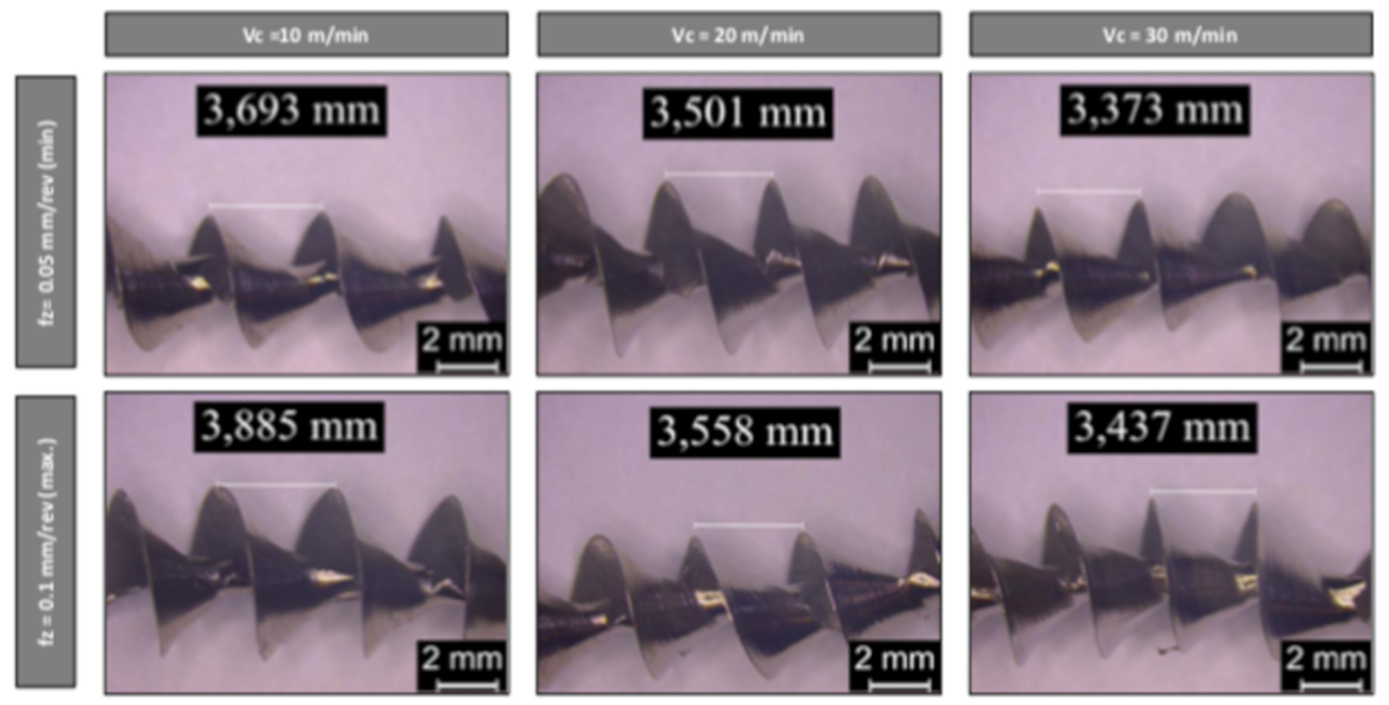
  • Regarding the chip geometry, a greater feed led to a smaller chip length, while no big differences were observed with the variation of cutting speed. Moreover, a metallographic analysis of the chip cross section showed that a serrated chip formation process was also present during drilling of titanium produced by WAAM.
  • Hole quality was also found to be affected by the materials’ manufacturing process. Burr height values were approximately 0.1 mm lower in the workpieces produced by WAAM. This can be explained by the higher hardness and mechanical properties of the additive-manufactured material. The hole diameter and surface roughness values were in the tolerance range required in the aeronautics industry for airframe parts.
Overall, from this study, it can be concluded that the workpieces produced by WAAM yield better performance in terms of mechanical properties and burr height, but higher cutting forces would be obtained under the same drilling conditions.
Future research works should consider the influence of the geometrical characteristics of the drill in the cutting process in order to obtain an optimized tool for this new workpiece material. Other lines of research to consider cover the study of different drilling parameters, considering the variance and repeatability with a large sample-size experiment analyzing the wear of the drill. Also of interest is the comparative study of the machinability of the material manufactured by this additive technology versus other material deposition technology such as selective laser melting (SLM) or laser metal deposition (LMD).

Author Contributions

Conceptualization, U.A., F.V., and A.S.; Data curation, U.A. and F.V.; Investigation, U.A. and F.V.; Methodology, U.A. and A.S.; Resources, A.S.; Supervision, A.S.; Validation, T.A.; Writing—original draft, U.A., F.V., and A.S.; Writing—review & editing, T.A. All authors have read and agreed to the published version of the manuscript.

Funding

This research was funded by the vice-counseling of technology, innovation, and competitiveness of the Basque Government grant agreement kk-2019/00004 (PROCODA project).

Acknowledgments

The authors thank the companies ADDILAN (Spain) and KENDU tools (Spain) for the technical and material support given to this study, as well as Paul Diego Martin for your collaboration.

Conflicts of Interest

The authors declare no conflict of interest.

Acronyms

AbbreviationDefinition
AMAdditive Manufacturing
WAAMWire Arc Additive Manufacturing
EASAEuropean Union Aviation Safety Agency
LMDLaser Melting Deposition
SLMSelective Laser Melting
EBMElectron Beam Melting
PAWPlasma Arc Welding
AMSAerospace Material Specification
IRInfrared Spectroscopy
CNCComputer Numerical Control
MQLMinimum Quantity Lubrication
UTSUltimate Tensile Stress
YSYield Strength
VcCutting Speed

References

  1. Wohlers, T. Additive Manufacturing and 3D Printing, State of the Industry; Annual Worldwide Progress Report; Wohlers Associations: Colorado, USA, 2012. [Google Scholar]
  2. Liberini, M.; Astarita, A.; Campatelli, G.; Scippa, A.; Montevecchi, F.; Venturini, G.; Durante, M.; Boccarusso, L.; Minutolo, F.M.C.; Squillace, A. Selection of optimal process parameters for wire arc additive manufacturing. Procedia CIRP 2017, 62, 470–474. [Google Scholar] [CrossRef]
  3. Venturini, G.; Montevecchi, F.; Scippa, A.; Campatelli, G. Optimization of WAAM deposition patterns for T-crossing features. Procedia CIRP 2016, 55, 95–100. [Google Scholar] [CrossRef] [Green Version]
  4. Ho, A.; Zhao, H.; Fellowes, J.W.; Martina, F.; Davis, A.E.; Prangnell, P.B. On the origin of microstructural banding in Ti-6Al4V wire-arc based high deposition rate additive manufacturing. Acta Mater. 2019, 166, 306–323. [Google Scholar] [CrossRef]
  5. Wu, B.; Pan, Z.; Ding, D.; Cuiuri, D.; Li, H.; Fei, Z. The effects of forced interpass cooling on the material properties of wire arc additively manufactured Ti6Al4V alloy. J. Mater. Process. Technol. 2018, 258, 97–105. [Google Scholar] [CrossRef] [Green Version]
  6. Wang, F.; Williams, S.; Colegrove, P.; Antonysamy, A.A. Microstructure and mechanical properties of wire and arc additive manufactured Ti-6Al-4V. Metall. Mater. Trans. A Phys. Metall. Mater. Sci. 2013, 44, 968–977. [Google Scholar] [CrossRef]
  7. Artaza, T.; Alberdi, A.; Murua, M.; Gorrotxategi, J.; Frías, J.; Puertas, G.; Melchor, M.A.; Mugica, D.; Suárez, A. Design and integration of WAAM technology and in situ monitoring system in a gantry machine. Procedia Manuf. 2017, 13, 778–785. [Google Scholar] [CrossRef]
  8. Rodrigues, T.A.; Duarte, V.; Miranda, R.M.; Santos, T.G.; Oliveira, J.P. Current Status and Perspectives on Wire and Arc Additive Manufacturing (WAAM). Materials 2019, 12, 1121. [Google Scholar] [CrossRef] [PubMed] [Green Version]
  9. Lütjering, G.; Williams, J.C. Titanium, 2nd ed.; Springer: Berlin/Heidelberg, Germany, 2007. [Google Scholar]
  10. Ding, D.; Pan, Z.; Cuiuri, D.; Li, H. Wire-feed additive manufacturing of metal components: Technologies, developments and future interests. Int. J. Adv. Manuf. Technol. 2015, 81, 465–481. [Google Scholar] [CrossRef]
  11. Tabernero, I.; Paskual, A.; Álvarez, P.; Suárez, A. Study on Arc Welding Processes for High Deposition Rate Additive Manufacturing. Procedia CIRP 2018, 68, 358–362. [Google Scholar]
  12. Le Coz, G.; Marinescu, M.; Devillez, A.; Dudzinski, D.; Velnom, L. Measuring temperature of rotating cutting tools: Application to MQL drilling and dry milling of aerospace alloys. Appl. Therm. Eng. 2012, 36, 434–441. [Google Scholar] [CrossRef]
  13. Xu, J.; Mkaddem, A.; El Mansori, M. Recent advances in drilling hybrid FRP/Ti composite: A state-of-the-art review. Compos. Struct. 2016, 135, 316–338. [Google Scholar] [CrossRef] [Green Version]
  14. Sharif, S.; Abd, E.; Sasahar, H. Machinability of Titanium Alloys in Drilling. In Titanium Alloys: Towards Achieving Enhanced Properties for Diversified Applications; Books on Demand: London, UK, 2012; pp. 117–138. [Google Scholar]
  15. Nouari, M.; Makich, H. On the Physics of Machining Titanium Alloys: Interactions between Cutting Parameters, Microstructure and Tool Wear. Metals 2014, 4, 335–358. [Google Scholar] [CrossRef] [Green Version]
  16. Abdelhafeez, A.M.; Soo, S.L.; Aspinwall, D.K.; Dowson, A.; Arnold, D. Burr formation and hole quality when drilling titanium and aluminium alloys. Procedia CIRP 2015, 37, 230–235. [Google Scholar] [CrossRef]
  17. Dornfeld, D.A.; Kim, J.S.; Dechow, H.; Hewson, J.; Chen, L.J. Drilling burr formation in titanium alloy. CIRP Ann. 1999, 48, 73–76. [Google Scholar] [CrossRef]
  18. Zhu, Z.; Sui, S.; Sun, J.; Li, J.; Li, Y. Investigation on performance characteristics in drilling of Ti6Al4V alloy. Int. J. Adv. Manuf. Technol. 2017, 93, 651–660. [Google Scholar] [CrossRef]
  19. Priarone, P.C.; Rizzuti, S.; Ruffa, S.; Settineri, L. Drilling experiments on a gamma titanium aluminide obtained via electron beam melting. Int. J. Adv. Manuf. Technol. 2013, 69, 483–490. [Google Scholar] [CrossRef]
  20. Available online: https://www.addilan.com/ (accessed on 29 November 2019).
  21. Zhu, Z.; Guo, K.; Sun, J.; Li, J.; Liu, Y.; Chen, L.; Zheng, Y. Evolution of 3D chip morphology and phase transformation in dry drilling Ti6Al4V alloys. J. Manuf. Process. 2018, 34, 531–539. [Google Scholar] [CrossRef]
  22. Daymi, A.; Boujelbene, M.; Salem, S.B.; Hadj Sassi, B.; Torbaty, S.; Sassi, B.H. Effect of the cutting speed on the chip morphology and the cutting forces. Manuf. Process. Eng. Mater. 2009, 78, 77–83. [Google Scholar]
Figure 1. (a) ADDILAN V0.1 wire arc additive manufacturing (WAAM) ([20]) and (b) schematic process sequence for wall manufacturing.
Metals 10 00024 g001
Figure 2. Dimensions of the samples for tensile tests in mm, Rz in μm, (a) and schematic representation of the location of the extracted samples (b).
Metals 10 00024 g002
Figure 3. Additively manufactured part sample after the deposition process (a). Milling operation (b), part sample after milling process (c).
Metals 10 00024 g003
Figure 4. (a) General arrangement of the equipment used for the drilling tests. (b) Front and side view of the used tools.
Metals 10 00024 g004
Figure 5. Thrust force evolution over time for a peck-drilling cycle.
Metals 10 00024 g005
Figure 6. Grain structure of the wall manufactured by plasma arc welding (PAW)-WAAM (a) at different heights and (b) from the top to bottom, as well as (c) micrographic pictures at different heights at 500X magnification.
Metals 10 00024 g006
Figure 7. Effect of cutting speed and feed rate on chip morphology in drilling of WAAM specimen.
Metals 10 00024 g007
Figure 8. Effect of cutting speed and feed rate on the chip “pitch” (workpieces produced by WAAM).
Metals 10 00024 g008
Figure 9. Metallographic analysis of the cross section of the chip for a workpiece produced by WAAM.
Metals 10 00024 g009
Figure 10. Effect of the cutting parameters on the (a) shear angle and (b)segment degree for a workpiece produced by WAAM.
Metals 10 00024 g010
Figure 11. Effect of the cutting parameters and material manufacturing process on the cutting torque.
Metals 10 00024 g011
Figure 12. Effect of the cutting parameters and material manufacturing process on the thrust force.
Metals 10 00024 g012
Figure 13. Effect of the cutting parameters and material manufacturing process on hole diameter.
Metals 10 00024 g013
Figure 14. Effect of the cutting parameters and material manufacturing process on the surface roughness of the hole.
Metals 10 00024 g014
Figure 15. Effect of the cutting parameters and material manufacturing process on the burr height.
Metals 10 00024 g015
Table 1. Nominal composition of welding wire and substrate.
MaterialChemical Composition (wt %)
AlVFeOCNHOtherTi
Wire5.5–6.753.5–4.50.220.12–0.2<0.05<0.03<0.015<0.4Bal.
Substrate5.5–6.753.5–4.5<0.3<0.2<0.08<0.05<0.015<0.4Bal.
Table 2. Welding parameters used for sample deposition with wire arc additive manufacturing (WAAM).
ParameterUnitValue
Torch Velocitymm/min400
Wire feedm/min6.7
Arc EnergyJ/mm1.125
Gas Pilotl/min1.2
Shielding Gasl/min12
Inter-bead Temperature°C600
Nominal wall dimension (LxWXH)mm210 × 15 × 105
Table 3. Cutting conditions for the drilling experiments.
ParameterLevel -1Level 0Level 1
Cutting speed (m/min)102030
Feed rate (mm/rev)0.050.0750.1
Table 4. Mechanical properties: ultimate tensile stress (UTS), yield strength (YS), and elongation at break (Elong). PAW-WAAM, plasma arc welding wire arc additive manufacturing.
SpecimenUTS (MPa)YS
(MPa)
Elong
(%)
Horizontal PAW-WAAM981 ± 36.3917 ± 19.311 ± 0.9
Vertical PAW-WAAM925 ± 18.2864 ± 22.815 ± 1.3
Oblique PAW-WAAM1094 ± 35.51020 ± 20.210 ± 0.5
Ti6Al4V>931>862>10
Table 5. Microhardness at different heights.
Hardness (HV 10)
PositionAverageSt. Dev.
Top294±4
Center304±7
Bottom304±5
Mean301±8
Table 6. Chemical composition of WAAM and laminated.
MaterialChemical Composition (wt %)
AlVFeOCNHOtherTi
PAW-WAAM6.340.170.160.020.0140.0030.00Bal.
Laminated5.5–6.753.5–4.5<0.3<0.2<0.08<0.05<0.015<0.4Bal.

