Review

Molten Metal Infiltration Methods to Process Metal Matrix Syntactic Foams

by
A. M. S-de-la-Muela
*,
L. E. G. Cambronero
and
J. M. Ruiz-Román
Department of Geological and Mining Engineering, Universidad Politécnica de Madrid, Rios Rosas 21, 28003 Madrid, Spain
*
Author to whom correspondence should be addressed.
Metals 2020, 10(1), 149; https://doi.org/10.3390/met10010149
Submission received: 22 December 2019 / Revised: 13 January 2020 / Accepted: 15 January 2020 / Published: 18 January 2020

Abstract

:
Metal matrix syntactic foams (MMSF) are foam composites obtained by filling hollow and/or porous particles into a metal matrix. MMSF are promising materials in defense, aerospace, automotive, marine and engineering applications. Mechanical and physical properties of MMSF can be tailored to reach better structural and/or functional behaviors by fitting processing and tailoring parameters. Some of these parameters are: reinforcement size, volume fraction, distribution of reinforcements and chemical composition. Three techniques are available to manufacture MMSF: Stir casting/vortex method (SC), powder metallurgy (P/M) and infiltration routes. Infiltration process is by far the main employed for making MMSF, it allows a large range of reinforcement (30 vol % to 78 vol %) and offers great advantages compared to other techniques. This paper reviews infiltration routes used to date, their advantages and drawbacks, the main processing parameters of each route, and a relation of representative studies developed to date on the synthesizing of MMSF by molten infiltration processes.

1. Introduction

Cellular metallic materials (foams, honeycombs and lattices) have great combinations of mechanical and physical properties [1]. The conversion of bulk metals into a cellular shape, i.e., the invention of foams, has been driven by the need to achieve lightweight engineering materials with increased specific strength, high damping, exceptional energy absorbing capabilities [2] and high thermal isolation [3]. Due to their good temperature resistance, metal foams offer exceptional potential to be applied in highly aggressive environments, such as cooling systems and heat shielding in power generation or transportation [4]. Nonetheless, the physical and mechanical properties of metal foams are mainly governed by its inner structure. This entails a great drawback because foam’s structure is elaborated during the manufacturing step. Unfortunately, the tailoring of metal foams’ properties requires monitoring the nucleation, the growth and the shape of the pores or cells. The thickness of walls of closed-cell or edges of opened-cell structures must be designed prior to use. In addition, industrial and engineering applications require expensive design modifications on manufacturing systems. For this reason, designing and manufacturing of metal foams is quite complex and expensive.
The desire to reduce production costs and tune the properties of metal foams promoted the development of metal matrix syntactic foams (MMSF) [2]. Metallic syntactic foams are mainly closed-cell porous solids where the porosity is introduced by hollow or porous heat resistant permanent particles (fillers or space holders) dispersed in a metallic matrix [4]. The porosity inside the fillers provides these materials with a closed-cell structure and makes them lightweight compared to the bulk matrix alloy [5]. Unusual characteristics of these materials can be sorted into two big families of materials. On the one hand, they can be considered as composite metal foams (CMFs), because they contain particles like hollow spheres. This term was firstly introduced by Rabiei et al. [6] to designate a specific type of MMSF. On the other hand, they can be classified as metal foams due to the porosity contained into filler particles [7]. Available studies on MMSF have shown that these composite foams have high heat insulation, damping of sound and vibration, great energy absorption and high specific stiffness [5]. The combination of properties for these materials are of high interest for the marine, defense, railway, automotive and aerospace industries [2,8,9]. Depending on the applications they have to meet, MMSF can be processed in several configurations such as foam filler tube (FFT) [10], foam core in sandwich panels [11] or without outer reinforcing.
Composite metal foams offer diverse advantages, the most critical are the enhanced mechanical properties (50 to 100% higher than metal foams) [12] and the tailoring of their density, mechanical, electrical and magnetic properties through the adequate selection of components (matrix and reinforcement particles), manufacturing processes [11] and final thermal/solution treatment. Typical stress-strain curves under uniaxial compression loads comprise three main regions: the first region corresponds to quasi-elastic behavior (from no load up to the yield stress), the second is known as the plateau region and usually exhibits a near flat and smooth stress and the third region corresponds to the densification of MMSF. An in-depth analysis of these issues is found in the study prepared by Duarte et al. [13]. Mechanical behavior can be characterized by means of international standards, e.g., the ISO-13314 (English) [14] and DIN-50134 (German) [15] are suitable for compressive testing while DIN-50099 (German) [16] is adequate for tensile testing. These guidelines establish a common framework for studying MMSF properties and comparing them with samples developed in other studies.
As it was mentioned above, components, manufacturing methods and heat/solution treatments govern the MMSF physical and mechanical properties. In the next section, components’ effects on properties will be briefly mentioned. Nevertheless, at the date of writing this paper and to the best of our knowledge, there is no other study which gathers and analyzes the latest liquid infiltration techniques to manufacture MMSF. Thus, this paper reviews infiltration routes used to date, their advantages and drawbacks, and the main processing parameters of each route. Moreover, it includes a comparison of representative studies developed to date on the synthesizing of MMSF by molten infiltration process.

2. Characteristics of MMSF

Usually, the melting point of the metal matrix determines the processing technique to be used. Bearing this in mind, metallic syntactic foams can be mainly processed by powder metallurgy (P/M) or liquid metallurgy (vortex or stir casting method (SC) and molten infiltration techniques (MIT)). P/M techniques are usually used for high processing temperatures (>1500 K) [17]. These methods can produce MMSF with a large range of metal volume fractions. The minimum range is that achieved by molten infiltration and the maximum is less than 100% due to sintering metal powders introducing residual porosity even without using fillers. The vortex method, or SC, entails relatively simple processing and can be scaled up for large production. Nevertheless, it also has limitations, like the potential fracture of fillers during mixing and low volume fraction of filler (around 50%) [18,19,20,21]. Molten infiltration techniques (MIT) are usually scaled up for low melting point alloys [22]. These hold high volume fraction of fillers [2,23] and found uniform dispersion of them [24]. MMSF can be made of a large variety of metal alloys. High melting point alloys, such as those based on Ti [25,26,27], Fe [28,29,30] or steel [17,31,32] are typically processed by P/M techniques. In contrast, low to medium melting point alloys (about from 505 K to 934 K), such as those based on Sn [33,34], Zn [2,5,19], Mg [20,35,36] or Al [37,38,39] are usually processed by liquid metallurgy.
Filler particles introduced as reinforcement in MMSF are lightweight aggregates with less density than water. They exhibit two main inner structures, hollow or porous [40,41,42]. The first type shows a mono-pore surrounded by a solid skeleton [43]. The second type shows a stochastic closed-cell pore distribution surrounded by a solid closed surface. The inner structure is not arbitrary; on the one hand, the empty space within the particles produce closed pores, which reduce critically the MMSF density and saving matrix metal, namely, saving costs. On the other hand, the monolithic shells create a continuous skeleton that results in enhanced strength and stiffness in comparison to unreinforced foams with same density [44]. Chemical composition of the available reinforcements varies greatly. Several studies have reported the utilization of natural-made fillers: Expanded vermiculite [45], pumice [40], lightweight expanded clay aggregate (LECA) [3,46], expanded perlite (EP) [47,48] and expanded glass (EG) [2,49]. In other cases, commercial or human-made lightweight aggregates have been successfully used: fly-ash cenospheres (FAC) [50,51,52], glass microballoons (GMB) [1,5], ceramic spheres (CMB) [11,53,54], carbon hollow spheres [55] and hollow metallic spheres [56]. Pores can contain traces of various gases like CO2, N2, H2O, CO and O2 [57] as a result of fillers manufacturing methods.
Apart from these two physical properties of reinforcements (chemical compositions and inner nature), there are several properties that must be controlled to optimize characteristics such as porosity (thickness-to-size ratio, shell porosity, compressive collapse strength, shrinkage and melting temperature) and wettability (surface roughness, coating properties and interface chemical reactions).
In terms of size, Puga et al. [3] observed that porous nature brittle fillers (such as LECA) tend to increase MMSF yield strength whilst fillers size and density increases and decreases respectively. This effect is due to higher filler sizes promoting thicker cell walls of the porous structure. However, the inverse effect of hollow nature particles was observed by Tao et al. [42] when fillers size was increased. Cell wall thickness is usually thinner than smaller size hollow fillers, so that less solid material bears load stresses. Orbulov et al. [58] and Taherishargh et al. [59] observed that hollow particles with high curvatures and small size (such as spherical shapes) show fewer buckling phenomena, high compression strength and mechanical stability.
Porosity determinates the density of the syntactic foams (SF), so that it is recommended to study it. In these terms, it is necessary establish the difference between true or intended porosity and residual or unintended porosity. True porosity is produced by filler particles’ inner voids. Hence it can be controlled by varying filler particles content or fitting the thickness-to-radius ratio of hollow particles [42]. The residual porosity concept refers to the unexpected porosity aided by processing defects. Palmer et al. [60] reported two main potential sources of residual porosity: gas entrapment released by cracked fillers and interstitial gases within preform bed that were not fully evacuated. Unintended porosity compromise MMSF properties so that it must be minimized.
Other physical properties are able to strongly affect mechanical behavior such as fillers wettability and chemical reactions between matrix-filler interface, which can consume prematurely the fillers shell thickness. Usually, the wetting capacity of a solid by a liquid depends on contact angle and it is related by the Young-Dupre’s equation referred to elsewhere [61]. When the contact angle (between solid/liquid) is obtuse, it results in poor wetting behavior. Fillers resist wetting by liquid and external forces are required to satisfy the MMSF manufacturing [62]. In order to achieve an acute contact angle, fillers can be conveniently coated with reactive alloys (those which improve the interfacial bonding between particles and matrix) [63]. Zhong et al. [64] and Li et al. [65] analyzed the interfacial reactions in composites of ceramic particles/Al–Mg. Schultz et al. [66], Li [67] and Bahrami et al. [68] reported that the introduction of reactive wetting agents as Mg can improve the interfacial bonding through reducing surface tension of certain molten metals (such as Al alloys). Nonetheless, chemical reactions can also be severe, to the extent that they are able to deteriorate solid shells and enable hollow particles to be infiltrated by liquid metal, according to observations of Santa Maria et al. [69], Braszczyńska-Malik et al. [57] and Myers et al. [39]. Fortunately, Lin et al. [70] and Al-Sahlani et al. [45] communicated that the severity of interfacial reactions can be limited reducing the exposure time at chemical reaction temperatures or varying filler and matrix content.

3. Molten Metal Infiltration Technique for Processing MMSF

Among the main applied manufacturing techniques (P/M, SC and MIT [3]) for processing MMSF, the most common is the so-called molten infiltration technique [71]. In general, infiltration methods can be described through three main steps: firstly, a bed of particles is prepared into a mold, subsequently a block of metal is melted and, then, liquid metal is infiltrated into the porous bed and, at the latter stage, the sample is cooled down at room temperature through natural or forced routes. Metal alloys commonly employed by this technique do not have high melting points, according to some studies [17,18,22,72]. Notwithstanding this, recent enhancements of liquid metal infiltration technology has enabled metal alloys with both low to medium (such as those based on tin [33,73], zinc [2,5], magnesium [57] and aluminum [39,56]) and high melting point (such as those based on iron [74,75], titanium [5] and bulk metallic glass or amorphous metals [55,76,77]) to be used to produce SF by this technique.
The filling step of molten infiltration methods presents a great drawback in contrast to SC and P/M techniques. For equal size spherical particles, the minimum and the maximum content of filler ranges from 52.36 vol % (in case of yielding the minimum packing density) to 63 vol % for the random close packing sphere (RCPS) or 74 vol % for the densest regular packing which follows a face-centered cubic cell (FCC), also called cubic close-packed (CCP) [42,71,74]. Hence, great barriers are found for processing MMSF with low volume fraction (<52.36 vol %) of fillers [18,78,79]. Since the amount of matrix material is determined by the interstitial space of the preform, this technique is not usually applied for synthesizing MMSF with large matrix volume fractions. Moreover, infiltration molds cannot support complex geometries thus MMSF processed by MIT have strong shape limitations [80]. However, it is possible to process MMSF with the highest volume fraction of fillers. This is by far one of the most significant advantages in comparison with the rest of the processing techniques [2,79].
The infiltration process can be understood as a combination of two molten flow routes. The first route describes the molten metal filling the interstices through the interparticle voids of the packed bed, and second route represents the molten metal through the surface of filler particles. The infiltration process is considered to be finished when the resistance of flow in the first route is higher than the flow resistance of the second route [81].
Melting infiltration techniques are able to produce MMSF based on both wetting and non-wetting matrix-filler systems. Those systems in which surface tension forces do not prevent the infiltration process takes place are known as wetting systems. Non-wetting systems are those in which a threshold infiltration pressure is needed to ensure molten metal fills porous bed of fillers [82]. In this case, if the imposed infiltration pressure surpasses the bearing strength of the microballoon particles, they could be crushed and be penetrated by the molten matrix alloy [1,57]. For this reason, some studies tend to associate MIT with high pressure methods that lead to reinforcement particles fracture [18,72,79]. Thus, and according to other studies [83,84,85], infiltration techniques are only able to infiltrate a thin bed of fillers, i.e., large components cannot be made in contrast to SC methods. In addition, the need to prepare special preforms of fillers can require additional costs [74,79] or complex production equipment [18]. Nonetheless, this route favors a uniform dispersion of fillers into the matrix without adding complementary processes (in contrast to SC routes) or promoting residual porosity (in contrast to P/M routes).
The structure and material of filler particles strongly depend on the molten metal temperature during the infiltration step. When the infiltration temperature is greater than shrinkage temperature of fillers, porosity tends to decrease due to the pressure applied. Thus, SF with this matrix-filler configuration cannot be processed through infiltration methods, in contrast to P/M techniques [30].
Synthesis of MMSF is a complex procedure, it usually requires a suitable combination of both tailoring and manufacturing parameters. On the one hand, tailoring parameters are considered to be those which are able to produce the larger fluctuations on MMSF mechanical properties. The most relevant of these parameters are sorted below: chemical composition of the metal matrix, heat treatment, porosity, hollow spheres properties [86,87], and aspect ratio H/D (height-to-diameter ratio) of samples [62]. On the other hand, manufacturing parameters are those that highly govern the successful of synthesis of this kind of composite foams. Furthermore, the extent of influence of each manufacture parameter strongly depends on the kind of liquid infiltration technique studied.
At the time of writing this paper, the available literature refers to six methods as the main ones employed to manufacture MMSF by liquid metal infiltration route. In spite of the reduced number of routes available, the decision to apply one instead of the other is not arbitrary. It depends on characteristics of components and processing parameters. Routes including non-wetting fillers require the assistance of external pressures to fill the interstitial voids of bed of fillers or preform. Through the Young-Laplace equation it is possible to estimate the minimum or threshold pressure needed to ensure the infiltration. If it is less than 0.1 MPa vacuum routes can be applied [88]. Preforms of wetting fillers can be spontaneously filled by molten metal due to its metallostatic weight [79]. The direction of infiltration (upward or downward) determines whether metallostatic weight acts as pressure agent.
These techniques can be sorted (as it is shown in Figure 1) depending on the manner the pressure is applied (directly or indirectly) and based on the infiltration direction (upward or downward).
In contrast with infiltration methods available for processing MMC, there are still routes which are not explored for manufacturing MMSF. These routes are known as Lorentz-force infiltration and Ultrasonic Infiltration, which are described in detail elsewhere [61] and are summarized briefly. Lorentz-force infiltration route is an indirect method in which external electromagnetic forces guide liquid metal flows through the open porosity of a preform of filler particles until interstitial voids are full filled. For that purpose, it is necessary that porous perform has been immersed into liquid metal to aid the subsequent infiltration. Through this novel approach, Mortensen et al. successfully synthesized an aluminum-alumina fiber composite [89]. In contrast, the Ultrasonic infiltration route is a direct method in which ultrasonic vibrations produce pressure waves into the liquid that promote the filling of reinforcement particles interstitial voids by liquid metal. In this context, diverse studies [90,91,92] supported this approach for Al alloys matrix composites manufacturing.

3.1. Counter-Gravity Pressure Infiltration Mechanically Assisted Method (CGIM)

This method consists of an upward infiltration in which a porous bed of filler particles is mechanically forced to be filled by liquid metal. In general, filler particles are firstly heat treated for removing any moisture and organic contaminants at low temperature (200–300 °C) for 20–30 min [41]. A mold is fulfilled with these particles; some studies apply a gently tapped over the mold in order to reach denser packing [2]. Alternatively, the mold can be filled in equally sized batches and vibration instigated between them [23]. Then, two meshes are placed at the top and at the bottom of the mold. A mesh is located over the ventilation hole to avoid exiting particles during the infiltration process [40,41]. A second mesh is placed at the other end of the mold to filter any film of metal oxide from the molten metal and to maintain the fillers fixed in place [45,93]. A block of metal alloy is placed in a crucible designed to ensure tight sealing with the mold whilst still allowing relative motion [10,40]. A metal block volume twice that of the fillers ensures full infiltration [41]. The mold is placed upside-down on the top of the block of metal alloy and the assembly is located into an isolating chamber [2]. To prevent any oxidation of metal matrix, assembling components and fillers, the chamber can be subjected to a vacuum (10−4 MPa) followed by purging with controlled atmosphere of inert gas (Argon [2,23,40]). The chamber with the assembly inside (depicted in Figure 2) is heating from room temperature until or above the melting point of matrix metal is reached and held at this temperature during a period for homogenization (usually 20–30 min) [4,45,94]. After this period, the assembly is removed from the chamber. The mold is pushed by means of a weight downwards in order to force the molten metal infiltring upwards via the natural porosity created by the filler particles. During the infiltration, ventilation holes allow the excitation of gases and excesses of molten metal [41]. When infiltration is complete, solidification can be supported artificially by means of a cooling down device until room temperature is achieved [23] or left cooling down under atmospheric conditions [93] and the MMSF is removed from the mold. Subsequently, MMSF can be subjected to a thermal treatment that stabilizes its mechanical properties through heat treatments, solution treatments or/and aging treatments [95]. Heat treatment applications are oriented to relax residual stresses effectively caused by infiltration and cooling steps. These treatments considerably enhance the foams’ mechanical properties [94].
Diverse authors worldwide have investigated this route and they reported various advantages and drawbacks. In these terms, Al-Sahlani et al. [49] and Taherishargh et al. [41] confirmed that most of the gases inside the natural porosity between filler particle packing are displaced successfully while the molten metal is infilling from bottom to top. The careful displacement of the residual porosity favors the obtaining of the expected mechanical and physical properties. Broxtermann et al. [2] and Borvinsek et al. [93] worked on this route and they reported that a gradient on density and strength properties is commonly developed in the infiltration direction. Although a gradient on properties may seem like a manufacturing defect, this opens the possibility to synthesize alternative foams called functionally graded syntactic foams (FGSF). Broxtermann et al. [23] reported that through double step compaction of filler materials, gradient effects can be avoided while the energy absorption efficiency of SF is increased. In addition, it was also determined that an adequate setting of steps and pressure of pre-compaction enables an increase in packaging of up to 78 vol % (overcoming the maximum packaging limit 74 vol % FCC) and MMSF density can be reduced by up to 0.72 g/cm3. Castro et al. [75] worked with this route and reported a new low-cost approach for applying this method. Broxtermann et al. [2] and Taherishargh et al. [95] found certain drawbacks studying this method: The infiltration pressure could decrease while liquid metal is filling the preform voids due to premature solidification effect. As a consequence, pressure of infiltration varies enough to reach incomplete infiltration or collapsing of reinforcement material.
The main manufacturing parameters for this technique are found to be: number of pre-compaction steps during filling [23], preheating of fillers [45], pressure of infiltration [93], temperature and time of infiltration [41]. The first one controls the packaging of fillers and, then, it affects the MMSF density and porosity. The fillers preheating minimizes the cooling down of the infiltration front of liquid metal and keeps the liquid viscosity stable. The pressure infiltration is limited by fillers cracking stress (Sc), it must be less than Sc and higher than the threshold pressure (pth) to fill the bed of fillers. The temperature and time of infiltration govern the liquid metal viscosity and the kinetics of chemical reaction.

3.2. Counter-Gravity Gas Pressure Infiltration (CGIG)

This process is based on the upward infiltration promoted by an injection of inert gas at high pressure. Authors such as Orbulov [82], Rohatgi et al. [96] and Luong et al. [97] have studied this route using CMB or FAC as filler particles and Al alloys as matrix. This procedure starts after fulfilling the infiltration mold with reinforcements. The mold can be rigorously tapped to achieve a denser packing than 57 vol % (max. 63 vol %), known as a randomly closed packed of equal spheres (RCPES) in case of a sphere of equal diameter. On both ends a mesh is located for maintaining particles fixed in place and avoiding chemical reaction between components during the matrix melting step. During the infiltration process, the oxide surface of molten metal is removed by the bottom mesh. Once the assembly is built, the packed tube of the filler is preheated at least 50 °C above the melting point of the metal matrix for preventing premature freezing during infiltration [82]. A block of metal matrix is situated in a crucible (into a pressure vessel) surrounded by a heating system, as shown in Figure 3. The heater system is turned on and the matrix is heated until a liquid state is reached. Then the pressure vessel is sealed and pressuring agent (Argon or Nitrogen gas) is introduced until reaching a setting value. At this value molten metal rises into the preform interstitial spaces. After an infiltration time ranging from 9 to 120 s, the process finalizes, and cooling step takes place until solidifies the sample of MMSF. Finally, before removing the sample from the assembly, the chamber is depressurized in order to prevent harmful leaks of contained gases [82,96].
A limitation of MIT is that the volume fraction of the filler is not easily reduced to small quantities. However, Rohatgi et al. [96] reported a variant route in which MMSF can be processed, including lower hollow microspheres volume fraction (<35%). For achieving this objective, a combination of two metallurgical techniques (P/M and Infiltration casting) took place. A mixture of metal matrix powder and hollow microspheres is prepared, and a mold is filled with this mixture. Then, the process follows as described previously.
This route has several advantages, which are discussed below: Orbulov [82] reported that this route saves a lot of processing time due to pre-heating, melting and infiltration steps that take place into the same vessel. Therefore, time is not wasted in removing the preform mold from the heating furnace and then forcing the infiltration. Rohatgi et al. [96] reported that upward infiltration leads an easy and natural manner to evacuate gases from interstitial voids. Furthermore, a modification was applied to reduce the minimum porosity limit to less than 35%. Pre-mixing of fillers and powder of metal matrix enables fewer fillers to be used than in conventional approaches. Nonetheless, during the infiltration, liquid trends to increase its viscosity and it can compromise the infiltration process.
The main manufacturing parameters that control this route are temperature, pressure and time of infiltration [82,97]. Analogous to CGIM, infiltration pressure is influenced by the tailoring parameters (reinforcement size, volume fraction and fillers fracture strength) [96] and must be higher than threshold pressure, which can be accurately estimated by means of Kaptay’s equation described elsewhere [82].
The infiltration temperature must be less than the shrinkage temperature, because the closing temperatures cause the gas in the filler to be released, and their porosity is less than the initial porosity [96]. For short infiltration times, it was found the infiltrated length can be estimated through the product between the applied pressure and the square root of time [82].

3.3. Downward Pressure Infiltration Mechanically Assisted Technique (DIM)

A good practice before beginning the synthesis of MMSF is sieving the as-received set of fillers and removing crushed and deteriorated particles [63]. It reduces the incorporation of heterogeneous particles and fragments that vary mechanical properties. It is common that fillers contain volatile substances accumulated that increase matrix porosity. By means of drying treatment at constant temperature during 20 to 30 min, this is minimized. Infiltration molds must be cleaned and adequately coated to prevent any chemical reaction and/or to facilitate the MMSF sample removal. The mold is sealed at its bottom end by an also coated solid metal disk (high melting point metal) [46,98]. Its role is avoiding molten metal exits prior to completing the infiltration. Furthermore, the inner diameter of the mold is slightly greater than the sealing disk and during infiltration the space between them ensures the evacuation of interstitial gases. Consecutively, a bed of loose fillers is prepared into the coated mold. Microballoons are filled and vertically pressed [1] to a set value ranging from 0.5 MPa [51,70] to 0.8 MPa [63,86] for a few minutes. The assembly (shown in Figure 4) is preheated until the melt point of the metal matrix is reached. Concurrently, the metal matrix is melted and held until thermal equilibrium is reached. Then, molten metal is poured into the preheated mold and a mechanical device pressurizes the top of liquid metal to promote downward infiltration into the porous bed [51,81,86]. Infiltration pressure is maintained until the block of MMSF is completely solidified [1,70].
This technique was slightly modified by Altenaiji et al. [81], Tao et al. [71] and Zhang et al. [46]. They do not apply a preheating or a pressing step on the fillers. The block of metal matrix is placed over the fillers. Then, another disk of (high melting point) metal is placed on the top of the matrix as thermal damping when the ram presses the assembly. The disk is slightly lower than mold and enables motion. The assembly is heated at 50 °C above the matrix melting point and is held for a period of time. Then, the ram is pressed for promoting the infiltration until a pressure around 3 to 4 MPa is reached [46,71] depending on fillers crack resistance. When the molten metal has fully solidified, the sample is removed of the mold.
This method has diverse advantages in comparison to other liquid infiltration techniques. Altenaiji et al. [81], Tao et al. [71] and Zhang et al. [46] indicated that this method saves time and costs due to processing steps that can be simplified following their manufacturing procedures. In addition, unlike other routes, this method does not require expensive gas pressure or vacuum systems. The heating step usually takes place without vacuum; therefore, it can be used as an inductive or resistance furnace. Therefore, this technique is highly versatile for producing MMSF. Tao et al. [71] also indicated that this process allows MMSF to synthesize, including up to 74 vol % of microballoons. They also successfully reduced the minimum content of microballoons from 57 vol % to 30 vol % premixing the fillers with metal powder. The study found that, for reaching best energy absorption capability, a 50% of metal matrix is the optimum volume fraction. Altenaiji et al. [81] reported in their study that this method promotes uniform distribution or reinforcements and favors excellent bonding between microballoons and the matrix. This method is also suitable for manufacturing bimodal MMSF (i.e., dual size fillers embedded into the metal matrix) according to Tao et al. [42]. These MMSF offer advantageous properties such as a smooth and near horizontal energy absorption regime during the filler crushing step (flat plateau regime), high plateau stress and good ductility. Zou et al. [50] manufactured an effective multilayer structure of MMSF core through this method as an armor panel.
The main manufacture parameters which govern this route are: the melt temperature, which is about 50 °C above the liquidus and ensures suitable viscosity, the filler preheating temperature, which is close to the matrix liquidus in order to avoid thermal shock during manufacturing [46], the infiltration pressure and the ratio reinforcement-matrix [75].

3.4. Downward or Gravity Inert Gas Assisted Pressure Infiltration Technique (DIG)

In this case, the method is based on a downward infiltration aided by a pressurized inert atmosphere which acts over liquid metal. This technique was successfully reported by Palmer et al. [60] and Balch et al.’s [99] investigations. As a preparation step, the infiltration mold is coated to avoid future chemical reactions [5] and to ensure easy MMSF removal [39]. It is recommended to clean reinforcements by ultrasonic devices in organic solvent and/or dried in vacuum for removing volatile substances [55]. The mold is filled up to half height with the hollow particles and it is gently taped in order to obtain a denser packing (around 65 vol %) [56,58]. An insulator layer is placed over the fillers; its role is to avoid any contact between MMSF components [88], filter any metal oxide layer during infiltration procedure [5,99] and keep the particles fixed in position [56]. An ingot of metal alloy is placed into the container as shown below in Figure 5. The assembly is then placed into a chamber (Figure 5b) and exposed to vacuum atmosphere [76]. Due to vacuum environment, the matrix melting is achieved with induction coils. When metal is completely liquid, a liquid cork surrounds the metal and seals the fillers at vacuum [69,99]. After that, the vessel is pressurized while a pressure difference is created above and under the sealing of liquid cork which induces the metal infiltration across the insulator mesh into the evacuated preform [39,88]. Finally, the assembly is cooled in different manners, as reported Lin et al. [76] by being submerged into a mixture of NaCl solution and ice cubes to quickly cool it down or through a controlled cooling rate, resulting in a minimal unintentional porosity according to Balch’s study [99].
Alternatively, Szlancsik et al. [56] reported a procedure (Figure 5a) in which reinforcements are preheated prior to use. Hereafter, liquid metal is poured into the mold over the insulator mesh. An inert atmosphere is injected into the vessel to promote the infiltration process. During the process, gases between particles are evacuated by means of a ventilation nozzle at the bottom of the vessel. This approach avoids the vacuum condition during the melting process. Therefore, processing steps are reduced in number and it turns into a cost-effective method to synthesize MMSF.
Many researcher groups have been working on this method and they reported the following key points: Sant Maria et al. [69], Szlancsik et al. [56], Lin et al. [76] successfully applied a great range of infiltration pressures, ranging from 0.04 to 6 MPa. The system selected by Palmer et al. [60] may aid the scale up of the process and extend to highly complex geometries. The simple set-up and the low pressure applied (475 KPa) promoted a precise monitoring of residual porosities nucleation mechanism. In addition, by varying crucible dimensions and infiltration temperature it was possible to limit the development of this mechanism. These results suggest that this approach can be scaled up. H. Lin et al. [76] and A.H. Brothers, D.C. Dunand [77] reported that this method can also be successfully scaled up to manufacture amorphous MMSF with a relative density of 50%. In addition, in those cases in which pressure infiltration is significantly higher than the threshold pressure of the bed of particles, the un-infiltrated voids can be neglected. Nonetheless, a reinforcement particle containing thin or deteriorated shell can be easily infiltrated by molten metal (the amount of them is usually less than 3 vol %) as it was indicated by Katone et al. [7]. L. Pan et al. [5] reported that infiltration pressure can be reduced to promote the wetting and the interfacial bonding with the matrix by coating reinforcement particles prior to use. Approaches including negative pressures have been applied and better results have been achieved in the evacuation of the interstitial gases as in case of Braszczynska-Malik et al.’s [57] study. R.A. Palmer et al. [60] observed that the mold material plays a critical role. Coatings applied on the inner surface of the mold to avoid the molten metal adherence can compromise the melt-crucible seal. Leakages can occur if the coating layer is too thick, thus it has to be applied carefully. Also, it was observed that the use of relatively low pressures of infiltration can promote unintended porosity.
The main manufacture parameters which govern this route are processing temperature [60], infiltration pressure and time of infiltration, which defines length of infiltration [58,88].

3.5. The Pressure-Less Infiltration Method (DPLI)

This method is based on the infiltration of a bed of fillers promoted just by metallostatic weight of the matrix. Due to the application of the gravity-fed system, it is vital to use an infiltration recipient with enough venting nozzles to evacuate whole gases during the process. It enables the use of hollow [11,36,52,74,100,101,102,103] or porous [3] particles. The mold filling step can be combined with gentle shaking after each batch filling for a denser packing, according to Licitra et al. [101]. Depending on the assembly (Figure 6a), a set of meshes are placed over the inlets and vents to avoid filler movement. These are made of high temperature material (alumina or fiberglass) [3,74,101]. The fulfilled mold is preheated close to the metal matrix melting point [11] to aid its infiltration and avoid the freeze of molten metal. To save costs it can be also preheated at half temperature. At the same time, the matrix is melted and held inside a crucible for homogenization [3]. The molten metal is poured over feed sprues and the gases are passively evacuated by means of vent nozzles [11,74,101].
Castro et al. [74] developed wire mesh inserts in the reinforcement arrangement to obtain a fixed and structured bed of particles (shown in Figure 6b). However, the as-fabricated MMSF still contains the mesh inserts, resulting in an anisotropic structure. Myers et al. [80] designed an innovative route to synthesize MMSF based on 3D printing. Microballoon samples were made by binder jet 3D printing, then they were cured through heat treatment. Cured samples were sintered at 1250 °C in order to get a bed of bonded fillers. Subsequently, sintering parts are submerged into a super-heated liquid metal (aluminum at 1250 °C) during a period from 4 to 16 h. The combination of superheating and a large period of exposing overcomes the surface tension forces which hinder the infiltration. This alternative route allows making MMSF of complex geometries without wasting material resources and investing in mold designing.
Alternatively, Rabiei et al. [6,104] introduced a new approach similar to Licitra’s set-up in which molten metal was poured into a parallel vertical sprue connected at the bottom of the preform mold, the top is open and acts as an evacuation device. Subsequently, the metallostatic weight of the melt forces us to initiate the infiltration process from the base to the top of the preform. During this step, the melt displaces interstitial gas which are evacuated through the top of the mold.
Pressure-less routes do not require a vacuum, gas pressure or centrifugal forces to reach a complete infiltration. Thus, it is considered as a simple and cost-effective manufacturing process, according to Castro et al. [74]. This route allows the synthesis of MMSF with low-cost matrixes such as low carbon steel [74] or aluminum alloys [103]. Diverse authors, among them Yaseer Omar et al. [11,102] and Lamanna et al. [100] successfully processed a sandwich core MMSF panel and they proved its versatility. Furthermore, this route enables modification, including 3D printing steps as in the work of Myers et al. [80]. The 3D printing, sintering and pressure-less infiltration promoted a less restricted synthesis technique. To facilitate the infiltration of non-wetting fillers, Puga et al. [3] vibrated the mold during liquid pouring. Friction forces over LECA fillers reduced their true porosity and increased entrapment of gases into the molten matrix.
According to the above authors, the manufacturing parameters which govern this route are the following: metallostatic weight of molten metal, filler preheating temperature (that minimizes front liquid metal premature freezing during infiltration process) and the melt temperature, which enable the infiltration of the matrix between filler voids. [6,74,104].

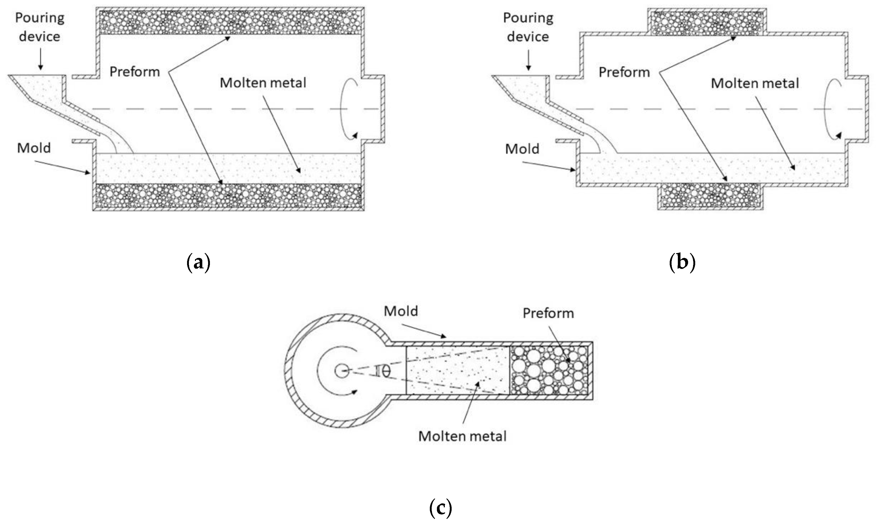
3.6. Centrifugal Infiltration Methods (CIM)

These kinds of routes are alternative methods in which liquid metal is forced to fill the voids between filler particles by centrifugal forces. According to the literature available to date, two main approaches can be distinguished to manufacture MMSF: conventional methods and modified methods, which are combinations of different processing routes [105,106].
Conventional methods employ a device constituted by a die casting modified with a rotation system (shown in Figure 7a). It was satisfactorily used by Sughisita et al. [33,73,107], Nishida et al. [108,109] and Wannasin et al. [34,110]. In this method, the infiltration mold is filled with certain quantity of filler to leave enough volume for the storage metal matrix over the bed. The arrangement is subjected to temperatures ranging from 50 °C to 100 °C above the melting temperature until reaching thermal equilibrium. At this point, the matrix is completely liquid, and the system rotates at a specific rotational speed in order to induce centrifugal forces inside the mold. The infiltration process begins when centrifugal forces over liquid metal front are greater than the filler threshold pressure. Infiltration finalizes when the porous preform is fulfilled by liquid metal. Then, the heating system is turned off and the mold is cooled to ambient temperature. Sugishita et al. [33,107] and Wannasin [34] worked on this approach. In the first case, a combined force of 1500 G (times gravity) at 100 °C above melting point was enough to ensure full infiltration for Al alloys-Carbon flakes components. For an Sn-Carbon flakes system, 380 G and a temperature of 50 °C above melting point was enough to reach the same results. Wannasin et al. [34,110] studied the effect of using metal in excess. The device worked at 2700 rpm, about 15 MPa, with 41–59 vol % fillers. They found that excessive mass increases inertial forces, which promote full infiltration.
Other authors such as Ferreira et al. [105,106] used modified methods. In these terms, samples of MMSF were previously processed by the vortex method. Hereafter, these samples were introduced into a die casting mold modified with a rotating system (Figure 7b) and were heated at matrix melting point. The liquid mixture was rotated at 750 rpm for a minute. Centrifugal forces segregated reinforcement particles by density. Samples exhibit a graded composition in the radial direction due to centrifugal forces acting dissimilarly on fillers and molten metal. Properties are governed by fillers and their distribution. Particles are concentrated in inner rings whilst the zone without fillers is mainly located in outer rings. Between these two zones, properties vary radially from an MMSF to a metal block. This kind of SFs are known as functionally graded MMSF (FGMMSF).
Diverse authors have found great advantages in using indirect processing routes such as centrifugal infiltration. In fact, Ferreira et al. [105,106] designed a modified approach for processing FGMMSF whose heterogeneous properties are able to increase the application range of the MMSF family. Previously, theoretical models were developed by Nishida et al. [108] to assess the effects of different preform shapes on manufacturing parameters. Three main approaches were investigated: a cylindrical preform shape (Figure 8a), a small bed of fillers in comparison to the volume of molten metal (Figure 8b) and a conventional mold which volume was fulfilled with a preform and molten metal (Figure 8c). Results demonstrated that pressure due to centrifugal forces in the latter case is higher than in the above two cases and this is due to the small angle (Figure 8c) at the rotation center with regard to the infiltration front.
Sughisita et al. [107] observed certain hinderances during infiltration process. Reinforcement particles subjected to centrifugal forces trend to release filler inner gases to the molten metal. If inertial rotational forces are high enough, then these gases are not able to leave the liquid metal. Thus, gases are incorporated into the matrix in the shape of residual porosity. MMSF properties change unpredictably as a function of this effect. Therefore, it is highly recommended to set angular velocity to centrifugal forces to allow the filling of interstitial voids by the matrix without entrapping gases into metal matrix, or coating fillers to avoid gases evacuation. In addition, they observed gravity segregation on reinforcement dispersion that trigged density heterogeneities into MMSF samples. Nevertheless, Wannasin et al. [34,110] placed a pair of meshes at the both ends of the infiltration mold. The mesh at the bottom allowed gases that exited the mold during the infiltration process whilst the mesh on the top hindered the reinforcement particles’ movement. This modification facilitates minimizing or avoiding the above undesirable effects (matrix porosity, high-density dispersion and gravity segregation).
The main manufacturing parameters which control this route according to the literature available to date are casting temperature that set the fluidity necessary to begin the process and pressure infiltration that ensures the infiltration takes place and is governed by rotational speed and bed shape [33,108].

4. Conclusions

Studies available to date about MMSF manufacturing routes refer to molten infiltration techniques (MIT) as quite limited routes. This is probably due to outdated knowledge which undermines the recent advantages of infiltration routes. In this context, the present research has tried to gather the enhancements and achievements reached to date by MMSF processing researchers to prevent future MIT distortion.
MIT reach a high-volume fraction of the filler, specifically up to 74 vol % for MMSF, which employs equally sized spherical particles. Recent attempts in the CGIM route have been able to overcome this maximum limit applying an adequate set of pre-compacting steps of fillers, reaching close to 78 vol % of fillers. Typical barriers found for reducing the minimum volume fraction of fillers (theoretically 52.36 vol %) have also been overcame. For this purpose, metal matrix was introduced in both powder and liquid state. Powder metal was introduced as space holder between filler particles, whilst liquid metal was infiltrated into interstitial voids (between powder and reinforcements). Through this approach, it was possible in DIM and CGIG routes to reduce the currently minimum limit of filler particles from 52.36 vol % to 30 vol %. These enhancements have allowed an increasingly large range of filler volume fractions.
Limitations such as the required high pressure infiltration for successfully processing MMSF are common for certain kinds of routes. Some of them are the so-called CIM, which can require 15 MPa, or DIG route, which might need 6 MPa to ensure the infiltration of an interstitial filler porosity by liquid metal. Nevertheless, methods are available that are more respectful with fillers such as DPLI, which do not require additional pressure assistance, or DIG, which can work with combinations of vacuum and low-pressure atmospheres. In any case, crushing of fillers (owing to excessive infiltration pressures) can be minimized by estimating the threshold pressure and fillers fracture strength, and their respective setting. Suitable setting of both latter parameters has allowed the infiltration of a large preform of fillers in diverse routes, such as DIG. Thus, the common limitation in which only a thin bed of space holders (particles) can be infiltrate by molten infiltration methods should be reconsidered. It is important to note that preparation of preforms can require additional costs, such as filler particles coating with wetting agents. Fortunately, these extra costs can be offset using low-cost routes such as DIG, DPLI or using low-cost fillers like pumice, lightweight expanded clay aggregate (LECA), expanded perlite (EP), expanded glass (EG) and fly ash cenospheres (FAC).
High temperature conditions for holding the liquid metal state may favor corrosive effects on production equipment that deteriorate it prematurely. Thus, these routes were not usually associated with high melting point alloys. Nevertheless, diverse studies gathered in this research have demonstrated that high melting SF alloys can be also synthesized by MIT, such as CGIM or DPLI in case of Fe alloys matrices and DIG in case of matrices of Ti alloys or BMG (monocrystalline metallic alloys). For this purpose, graphite molds can be a great solution to safely manage high temperature processing. In other cases, complex production equipment is required to reach vacuum, inert gas atmospheres, high pressures or inductive heat sources which subtract versatility to processing techniques, such as DIG or CGIG. Nonetheless, DPLI (without pressure assisted) routes only need enough metallostatic weight to promote infiltration and, owing to that, these ease the manufacturing procedure. Moreover, through DPLI and DIG routes, MMSF holding complex shape geometries can be manufactured. Thus, MIT can be applied for processing MMSF with complex shapes as well as P/M techniques.
In terms of future lines, this research has discovered some MMSF processing gaps. Despite the demonstrated great versatility of infiltration methods, SF made up of high melting matrix and reinforcements with low-to-medium shrinkage temperature continue to be difficult to process, in contrast to P/M routes. Thus, achieving the processing of this special kind of MMSF by means of any MIT would increase the applicability of this family of processing routes. In the same vein, it is interesting to note that there are still two routes of MIT commonly applied for MMC, which have not been explored yet for processing MMSF. These are the so-called Lorentz-force infiltration and Ultrasonic infiltration routes. Both methods were effectively applied for synthesizing Al alloy composites; therefore, these could be also used for producing MMSF.

Author Contributions

Conceptualization, A.M.S.-d.-l.-M. and L.E.G.C.; validation, A.M.S.-d.-l.-M., L.E.G.C. and J.M.R.-R.; investigation, A.M.S.-d.-l.-M.; writing—original draft preparation, A.M.S.-d.-l.-M. and L.E.G.C.; writing—review and editing, A.M.S.-d.-l.-M., L.E.G.C. and J.M.R.-R.; supervision, L.E.G.C. and J.M.R.-R. All authors have read and agreed to the published version of the manuscript.

Funding

This research received no external funding.

Conflicts of Interest

The authors declare no conflict of interest.

References

  1. Zhang, Q.; Lin, Y.; Chi, H.; Chang, J.; Wu, G. Quasi-static and dynamic compression behavior of glass cenospheres/5A03 syntactic foam and its sandwich structure. Compos. Struct. 2017, 183, 499–509. [Google Scholar] [CrossRef]
  2. Broxtermann, S.; Vesenjak, M.; Krstulović-Opara, L.; Fiedler, T. Quasi static and dynamic compression of zinc syntactic foams. J. Alloys Compd. 2018, 768, 962–969. [Google Scholar] [CrossRef]
  3. Puga, H.; Carneiro, V.H.; Jesus, C.; Pereira, J.; Lopes, V. Influence of particle diameter in mechanical performance of Al expanded clay syntactic foams. Compos. Struct. 2018, 184, 698–703. [Google Scholar] [CrossRef]
  4. Taherishargh, M.; Linul, E.; Broxtermann, S.; Fiedler, T. The mechanical properties of expanded perlite-aluminium syntactic foam at elevated temperatures. J. Alloys Compd. 2018, 737, 590–596. [Google Scholar] [CrossRef]
  5. Pan, L.; Yang, Y.; Ahsan, M.U.; Luong, D.D.; Gupta, N.; Kumar, A.; Rohatgi, P.K. Zn-matrix syntactic foams: Effect of heat treatment on microstructure and compressive properties. Mater. Sci. Eng. A 2018, 731, 413–422. [Google Scholar] [CrossRef]
  6. Rabiei, A.; O’Neill, A.T.; Neville, B.P. Processing and development of a new high strength metal foam. MRS Proc. 2004, 851, 517–526. [Google Scholar] [CrossRef]
  7. Katona, B.; Szebényi, G.; Orbulov, I.N. Fatigue properties of ceramic hollow sphere filled aluminium matrix syntactic foams. Mater. Sci. Eng. A 2017, 679, 350–357. [Google Scholar] [CrossRef] [Green Version]
  8. Zhang, B.; Lin, Y.; Li, S.; Zhai, D.; Wu, G. Quasi-static and high strain rates compressive behavior of aluminum matrix syntactic foams. Compos. Part B Eng. 2016, 98, 288–296. [Google Scholar] [CrossRef]
  9. Gupta, N.; Rohatgi, P.K. Metal Matrix Syntactic Foams: Processing, Microstructure, Properties and Applications; Gupta, N., Rohatgi, P.K., Eds.; DEStech Publications Inc.: Lancaster, PA, USA, 2014; ISBN 9781932078831. [Google Scholar]
  10. Taherishargh, M.; Vesenjak, M.; Belova, I.V.; Krstulović-Opara, L.; Murch, G.E.; Fiedler, T. In situ manufacturing and mechanical properties of syntactic foam filled tubes. Mater. Des. 2016, 99, 356–368. [Google Scholar] [CrossRef]
  11. Yaseer Omar, M.; Xiang, C.; Gupta, N.; Strbik, O.M.; Cho, K. Syntactic foam core metal matrix sandwich composite: Compressive properties and strain rate effects. Mater. Sci. Eng. A 2015, 643, 156–168. [Google Scholar] [CrossRef]
  12. Orbulov, I.N.; Májlinger, K. Description of the compressive response of metal matrix syntactic foams. Mater. Des. 2013, 49, 1–9. [Google Scholar] [CrossRef]
  13. Duarte, I.; Ferreira, J. Composite and Nanocomposite Metal Foams. Materials 2016, 9, 79. [Google Scholar] [CrossRef] [PubMed] [Green Version]
  14. International Organization for Standardization ISO 13314:2011. Mechanical Testing Of Metals—Ductility Testing—Compression Test For Porous And Cellular Metals; International Organization for Standardization: Geneva, Switzerland, 2011; pp. 1–7. [Google Scholar]
  15. German Institute for Standardisation (Deutsches Institut für Normung) DIN 50134. Testing of Metallic Materials—Compression Test of Metallic Cellular Materials; German Institute for Standardisation (Deutsches Institut für Normung): Berlin, Germany, 2008; p. 13. [Google Scholar]
  16. German Institute for Standardisation (Deutsches Institut für Normung) DIN 50099. Tensile Testing Of Metallic Cellular Materials; German Institute for Standardisation (Deutsches Institut für Normung): Berlin, Germany, 2015; p. 11. [Google Scholar]
  17. Weise, J.; Lehmhus, D.; Baumeister, J.; Kun, R.; Bayoumi, M.; Busse, M. Production and properties of 316l stainless steel cellular materials and syntactic foams. Steel Res. Int. 2014, 85, 486–497. [Google Scholar] [CrossRef]
  18. Vogiatzis, C.A.; Skolianos, S.M. On the sintering mechanisms and microstructure of aluminium-ceramic cenospheres syntactic foams produced by powder metallurgy route. Compos. Part A Appl. Sci. Manuf. 2016, 82, 8–19. [Google Scholar] [CrossRef]
  19. Daoud, A. Synthesis and characterization of novel ZnAl22 syntactic foam composites via casting. Mater. Sci. Eng. A 2008, 488, 281–295. [Google Scholar] [CrossRef]
  20. Daoud, A.; Abou El-khair, M.T.; Abdel-Aziz, M.; Rohatgi, P. Fabrication, microstructure and compressive behavior of ZC63 Mg-microballoon foam composites. Compos. Sci. Technol. 2007, 67, 1842–1853. [Google Scholar] [CrossRef]
  21. Rajan, T.P.D.; Pillai, R.M.; Pai, B.C.; Satyanarayana, K.G.; Rohatgi, P.K. Fabrication and characterisation of Al-7Si-0.35Mg/fly ash metal matrix composites processed by different stir casting routes. Compos. Sci. Technol. 2007, 67, 3369–3377. [Google Scholar] [CrossRef]
  22. Weise, J.; Salk, N.; Jehring, U.; Baumeister, J.; Lehmhus, D.; Bayoumi, M. Influence of powder size on production parameters and properties of syntactic invar foams produced by means of metal powder injection moulding. Adv. Eng. Mater. 2013, 15, 118–122. [Google Scholar] [CrossRef]
  23. Broxtermann, S.; Taherishargh, M.; Belova, I.V.; Murch, G.E.; Fiedler, T. On the compressive behaviour of high porosity expanded Perlite-Metal Syntactic Foam (P-MSF). J. Alloys Compd. 2017, 691, 690–697. [Google Scholar] [CrossRef]
  24. Kumar, V.R.; Rao, C.R.P.; Poornachandra; Suresh, R. Corrosion and Wear Studies on LM6 Grade Aluminum-Cenosphere Composite-An Experimental Approach. Mater. Today Proc. 2018, 5, 11667–11677. [Google Scholar] [CrossRef]
  25. Xue, X.B.; Zhao, Y.Y.; Kearns, V.; Williams, R.L. Mechanical and biological properties of titanium syntactic foams. In Proceedings of the TMS Annual Meeting, Seattle, WA, USA, 14–18 February 2010; TMS (The Minerals, Metals & Materials Society): Warrendale, PA, USA, 2010; Volume 2, pp. 129–135. [Google Scholar]
  26. Mondal, D.P.; Datta Majumder, J.; Jha, N.; Badkul, A.; Das, S.; Patel, A.; Gupta, G. Titanium-cenosphere syntactic foam made through powder metallurgy route. Mater. Des. 2012, 34, 82–89. [Google Scholar] [CrossRef]
  27. Xue, X.B.; Wang, L.Q.; Wang, M.M.; Lü, W.J.; Zhang, D. Manufacturing, compressive behaviour and elastic modulus of Ti matrix syntactic foam fabricated by powder metallurgy. Trans. Nonferrous Met. Soc. China English Ed. 2012, 22, 188–192. [Google Scholar] [CrossRef]
  28. Weise, J.; Baumeister, J.; Yezerska, O.; Salk, N.; Silva, G.B.D. Syntactic Iron Foams with Integrated Microglass Bubbles Produced by Means of Metal Powder Injection Moulding. Adv. Eng. Mater. 2010, 12, 604–608. [Google Scholar] [CrossRef]
  29. Lehmhus, D.; Weise, J.; Baumeister, J.; Peroni, L.; Scapin, M.; Fichera, C.; Avalle, M.; Busse, M. Quasi-static and Dynamic Mechanical Performance of Glass Microsphere- and Cenosphere-based 316L Syntactic Foams. Procedia Mater. Sci. 2014, 4, 383–387. [Google Scholar] [CrossRef]
  30. Luong, D.D.; Shunmugasamy, V.C.; Gupta, N.; Lehmhus, D.; Weise, J.; Baumeister, J. Quasi-static and high strain rates compressive response of iron and Invar matrix syntactic foams. Mater. Des. 2015, 66, 516–531. [Google Scholar] [CrossRef]
  31. Peroni, L.; Scapin, M.; Fichera, C.; Lehmhus, D.; Weise, J.; Baumeister, J.; Avalle, M. Investigation of the mechanical behaviour of AISI 316L stainless steel syntactic foams at different strain-rates. Compos. Part B Eng. 2014, 66, 430–442. [Google Scholar] [CrossRef]
  32. Weise, J.; Baumeister, J.; Ehinger, D.; Krüger, L.; Martin, U.; Junior, J.B.P. Investigation of Processing, Microstructure and Mechanical Behaviour of 304L TRIP Steel Foams Produced by Injection Moulding. Procedia Mater. Sci. 2014, 4, 63–67. [Google Scholar] [CrossRef] [Green Version]
  33. Sugishita, J.; Fujiyoshi, S.; Imura, T.; Ishii, M. A study of cast alloys with partially dispersed graphite II: The process of partial dispersion with uncoated flake graphites. Wear 1982, 82, 167–178. [Google Scholar] [CrossRef]
  34. Wannasin, J.; Flemings, M.C. Fabrication of metal matrix composites by a high-pressure centrifugal infiltration process. J. Mater. Process. Technol. 2005, 169, 143–149. [Google Scholar] [CrossRef]
  35. Huang, Z.; Yu, S.; Liu, J.; Zhu, X. Microstructure and mechanical properties of in situ Mg2Si/AZ91D composites through incorporating fly ash cenospheres. Mater. Des. 2011, 32, 4714–4719. [Google Scholar] [CrossRef]
  36. Anantharaman, H.; Shunmugasamy, V.C.; Strbik, O.M.; Gupta, N.; Cho, K. Dynamic properties of silicon carbide hollow particle filled magnesium alloy (AZ91D) matrix syntactic foams. Int. J. Impact Eng. 2015, 82, 14–24. [Google Scholar] [CrossRef]
  37. Vishwakarma, A.; Mondal, D.P.; Birla, S.; Das, S.; Prasanth, P. Effect of cenosphere size on the dry sliding wear behaviour LM13-cenosphere syntactic foam. Tribol. Int. 2017, 110, 8–22. [Google Scholar] [CrossRef]
  38. Sudarshan; Surappa, M.K. Synthesis of fly ash particle reinforced A356 Al composites and their characterization. Mater. Sci. Eng. A 2008, 480, 117–124. [Google Scholar] [CrossRef]
  39. Myers, K.; Katona, B.; Cortes, P.; Orbulov, I.N. Quasi-static and high strain rate response of aluminum matrix syntactic foams under compression. Compos. Part A Appl. Sci. Manuf. 2015, 79, 82–91. [Google Scholar] [CrossRef] [Green Version]
  40. Taherishargh, M.; Belova, I.V.; Murch, G.E.; Fiedler, T. Pumice/aluminium syntactic foam. Mater. Sci. Eng. A 2015, 635, 102–108. [Google Scholar] [CrossRef]
  41. Taherishargh, M.; Belova, I.V.; Murch, G.E.; Fiedler, T. Low-density expanded perlite–aluminium syntactic foam. Mater. Sci. Eng. A 2014, 604, 127–134. [Google Scholar] [CrossRef]
  42. Tao, X.F.; Zhang, L.P.; Zhao, Y.Y. Al matrix syntactic foam fabricated with bimodal ceramic microspheres. Mater. Des. 2009, 30, 2732–2736. [Google Scholar] [CrossRef]
  43. Balch, D.K.; Dunand, D.C. Load partitioning in aluminum syntactic foams containing ceramic microspheres. Acta Mater. 2006, 54, 1501–1511. [Google Scholar] [CrossRef]
  44. Couteau, O.; Dunand, D.C. Creep of aluminum syntactic foams. Mater. Sci. Eng. A 2008, 488, 573–579. [Google Scholar] [CrossRef]
  45. Al-Sahlani, K.; Taherishargh, M.; Kisi, E.; Fiedler, T. Controlled shrinkage of expanded glass particles in metal syntactic foams. Materials 2017, 10, 1073. [Google Scholar] [CrossRef] [Green Version]
  46. Zhang, L.P.; Zhao, Y.Y. Mechanical Response of Al Matrix Syntactic Foams Produced by Pressure Infiltration Casting. J. Compos. Mater. 2007, 41, 2105–2117. [Google Scholar] [CrossRef]
  47. Fiedler, T.; Belova, I.V.; Murch, G.E. On the thermal properties of expanded perlite—Metallic syntactic foam. Int. J. Heat Mass Transf. 2015, 90, 1009–1014. [Google Scholar] [CrossRef]
  48. Fiedler, T.; Taherishargh, M.; Krstulović-Opara, L.; Vesenjak, M. Dynamic compressive loading of expanded perlite/aluminum syntactic foam. Mater. Sci. Eng. A 2015, 626, 296–304. [Google Scholar] [CrossRef]
  49. Al-Sahlani, K.; Broxtermann, S.; Lell, D.; Fiedler, T. Effects of particle size on the microstructure and mechanical properties of expanded glass-metal syntactic foams. Mater. Sci. Eng. A 2018, 728, 80–87. [Google Scholar] [CrossRef]
  50. Zou, L.C.; Zhang, Q.; Pang, B.J.; Wu, G.H.; Jiang, L.T.; Su, H. Dynamic compressive behavior of aluminum matrix syntactic foam and its multilayer structure. Mater. Des. 2013, 45, 555–560. [Google Scholar] [CrossRef]
  51. Zhang, Q.; Lee, P.D.; Singh, R.; Wu, G.; Lindley, T.C. Micro-CT characterization of structural features and deformation behavior of fly ash/aluminum syntactic foam. Acta Mater. 2009, 57, 3003–3011. [Google Scholar] [CrossRef]
  52. Rohatgi, P.K.; Daoud, A.; Schultz, B.F.; Puri, T. Microstructure and mechanical behavior of die casting AZ91D-Fly ash cenosphere composites. Compos. Part A Appl. Sci. Manuf. 2009, 40, 883–896. [Google Scholar] [CrossRef]
  53. Wu, G.H.; Dou, Z.Y.; Sun, D.L.; Jiang, L.T.; Ding, B.S.; He, B.F. Compression behaviors of cenosphere-pure aluminum syntactic foams. Scr. Mater. 2007, 56, 221–224. [Google Scholar] [CrossRef]
  54. Dou, Z.Y.; Jiang, L.T.; Wu, G.H.; Zhang, Q.; Xiu, Z.Y.; Chen, G.Q. High strain rate compression of cenosphere-pure aluminum syntactic foams. Scr. Mater. 2007, 57, 945–948. [Google Scholar] [CrossRef]
  55. Brothers, A.H.; Dunand, D.C. Syntactic bulk metallic glass foam. Appl. Phys. Lett. 2004, 84, 1108–1110. [Google Scholar] [CrossRef] [Green Version]
  56. Szlancsik, A.; Katona, B.; Bobor, K.; Májlinger, K.; Orbulov, I.N. Compressive behaviour of aluminium matrix syntactic foams reinforced by iron hollow spheres. Mater. Des. 2015, 83, 230–237. [Google Scholar] [CrossRef] [Green Version]
  57. Braszczyńska-Malik, K.N.; Kamieniak, J. AZ91 magnesium matrix foam composites with fly ash cenospheres fabricated by negative pressure infiltration technique. Mater. Charact. 2017, 128, 209–216. [Google Scholar] [CrossRef]
  58. Orbulov, I.N.; Ginsztler, J. Compressive characteristics of metal matrix syntactic foams. Compos. Part A Appl. Sci. Manuf. 2012, 43, 553–561. [Google Scholar] [CrossRef] [Green Version]
  59. Taherishargh, M.; Belova, I.V.; Murch, G.E.; Fiedler, T. The effect of particle shape on mechanical properties of perlite/metal syntactic foam. J. Alloys Compd. 2017, 693, 55–60. [Google Scholar] [CrossRef]
  60. Palmer, R.A.; Gao, K.; Doan, T.M.; Green, L.; Cavallaro, G. Pressure infiltrated syntactic foams-Process development and mechanical properties. Mater. Sci. Eng. A 2007, 464, 85–92. [Google Scholar] [CrossRef]
  61. Sree Manu, K.M.; Ajay Raag, L.; Rajan, T.P.D.; Gupta, M.; Pai, B.C. Liquid Metal Infiltration Processing of Metallic Composites: A Critical Review. Metall. Mater. Trans. B 2016, 47, 2799–2819. [Google Scholar] [CrossRef]
  62. Orbulov, I.N. Compressive properties of aluminium matrix syntactic foams. Mater. Sci. Eng. A 2012, 555, 52–56. [Google Scholar] [CrossRef]
  63. Lin, Y.; Zhang, Q.; Ma, X.; Wu, G. Mechanical behavior of pure Al and Al-Mg syntactic foam composites containing glass cenospheres. Compos. Part A Appl. Sci. Manuf. 2016, 87, 194–202. [Google Scholar] [CrossRef]
  64. Zhong, W.M.; L’Esperance, G.; Suéry, M. Effect of current Mg concentration on interfacial reactions during remelting of Al–Mg(5083)/Al2O3p composites. Mater. Charact. 2002, 49, 113–119. [Google Scholar] [CrossRef]
  65. Guobin, L.; Jibing, S.; Quanmei, G.; Yuhui, W. Interfacial reactions in glass/Al-Mg composite fabricated by powder metallurgy process. J. Mater. Process. Technol. 2005, 161, 445–448. [Google Scholar] [CrossRef]
  66. Basu, J.; Ranganathan, S. Bulk metallic glasses: A new class of engineering materials. Sadhana Acad. Proc. Eng. Sci. 2003, 28, 783–798. [Google Scholar] [CrossRef]
  67. Li, B.; Luo, B.; He, K.; Zeng, L.; Fan, W.; Bai, Z. Effect of aging on interface characteristics of Al-Mg-Si/SiC composites. J. Alloys Compd. 2015, 649, 495–499. [Google Scholar] [CrossRef]
  68. Bahrami, A.; Pech-Canul, M.I.; Gutiérrez, C.A.; Soltani, N. Wetting and reaction characteristics of crystalline and amorphous SiO2 derived rice-husk ash and SiO2/SiC substrates with Al-Si-Mg alloys. Appl. Surf. Sci. 2015. [Google Scholar] [CrossRef]
  69. Santa Maria, J.A.; Schultz, B.F.; Ferguson, J.B.; Rohatgi, P.K. Al-Al2O3 syntactic foams—Part I: Effect of matrix strength and hollow sphere size on the quasi-static properties of Al-A206/Al2O3 syntactic foams. Mater. Sci. Eng. A 2013, 582, 415–422. [Google Scholar] [CrossRef]
  70. Lin, Y.; Zhang, Q.; Wu, G. Interfacial microstructure and compressive properties of Al-Mg syntactic foam reinforced with glass cenospheres. J. Alloys Compd. 2016, 655, 301–308. [Google Scholar] [CrossRef]
  71. Tao, X.F.; Zhao, Y.Y. Compressive behavior of Al matrix syntactic foams toughened with Al particles. Scr. Mater. 2009, 61, 461–464. [Google Scholar] [CrossRef]
  72. Peroni, L.; Scapin, M.; Avalle, M.; Weise, J.; Lehmhus, D. Dynamic mechanical behavior of syntactic iron foams with glass microspheres. Mater. Sci. Eng. A 2012, 552, 364–375. [Google Scholar] [CrossRef]
  73. Sugishita, J.; Imura, T.; Fujiyoshi, S. A study of cast alloys with partially dispersed graphite III: Characterization of high density dispersed surfaces. Wear 1983, 87, 181–190. [Google Scholar] [CrossRef]
  74. Castro, G.; Nutt, S.R. Synthesis of syntactic steel foam using gravity-fed infiltration. Mater. Sci. Eng. A 2012, 553, 89–95. [Google Scholar] [CrossRef]
  75. Castro, G.; Nutt, S.R. Synthesis of syntactic steel foam using mechanical pressure infiltration. Mater. Sci. Eng. A 2012, 535, 274–280. [Google Scholar] [CrossRef]
  76. Lin, H.; Wang, H.Y.; Lu, C.; Dai, L.H. A metallic glass syntactic foam with enhanced energy absorption performance. Scr. Mater. 2016, 119, 47–50. [Google Scholar] [CrossRef] [Green Version]
  77. Brothers, A.H.; Dunand, D.C. Amorphous metal foams. Scr. Mater. 2006, 54, 513–520. [Google Scholar] [CrossRef]
  78. Zhao, Y.; Tao, X.; Xue, X. Manufacture and mechanical properties of metal matrix syntactic foams. In Proceedings of the Materials Science and Technology Conference and Exhibition, MS and T’08, Pittsburgh, PA, USA, 5–9 October 2008; Volume 4, pp. 2607–2615. [Google Scholar]
  79. Rohatgi, P.K.; Gupta, N.; Schultz, B.F.; Luong, D.D. The synthesis, compressive properties, and applications of metal matrix syntactic foams. JOM 2011, 63, 36–42. [Google Scholar] [CrossRef]
  80. Myers, K.; Cortes, P.; Conner, B.; Wagner, T.; Hetzel, B.; Peters, K.M. Structure property relationship of metal matrix syntactic foams manufactured by a binder jet printing process. Addit. Manuf. 2015, 5, 54–59. [Google Scholar] [CrossRef]
  81. Altenaiji, M.; Guan, Z.W.; Cantwell, W.J.; Zhao, Y.; Schleyer, G.K. Characterisation of aluminium matrix syntactic foams under drop weight impact. Mater. Des. 2014, 59, 296–302. [Google Scholar] [CrossRef]
  82. Orbulov, I.N. Metal matrix syntactic foams produced by pressure infiltration-The effect of infiltration parameters. Mater. Sci. Eng. A 2013, 583, 11–19. [Google Scholar] [CrossRef] [Green Version]
  83. Mondal, D.P.; Jha, N.; Badkul, A.; Das, S.; Khedle, R. High temperature compressive deformation behaviour of aluminum syntactic foam. Mater. Sci. Eng. A 2012, 534, 521–529. [Google Scholar] [CrossRef]
  84. Mondal, D.P.; Das, S.; Jha, N. Dry sliding wear behaviour of aluminum syntactic foam. Mater. Des. 2009, 30, 2563–2568. [Google Scholar] [CrossRef]
  85. Mondal, D.P.; Das, S.; Ramakrishnan, N.; Uday Bhasker, K. Cenosphere filled aluminum syntactic foam made through stir-casting technique. Compos. Part A Appl. Sci. Manuf. 2009, 40, 279–288. [Google Scholar] [CrossRef]
  86. Lin, Y.; Zhang, Q.; Zhang, F.; Chang, J.; Wu, G. Microstructure and strength correlation of pure Al and Al-Mg syntactic foam composites subject to uniaxial compression. Mater. Sci. Eng. A 2017, 696, 236–247. [Google Scholar] [CrossRef]
  87. Sulong, M.A.; Taherishargh, M.; Belova, I.V.; Murch, G.E.; Fiedler, T. On the mechanical anisotropy of the compressive properties of aluminium perlite syntactic foam. Comput. Mater. Sci. 2015, 109, 258–265. [Google Scholar] [CrossRef]
  88. Orbulov, I.N.; Dobránszky, J. Producing metal matrix syntactic foams by pressure infiltration. Period. Polytech. Mech. Eng. 2008, 52, 35–42. [Google Scholar] [CrossRef] [Green Version]
  89. Andrews, R.M.; Mortensen, A. Lorentz-force-driven infiltration by aluminum. Mater. Sci. Eng. A 1991, 144, 165–168. [Google Scholar] [CrossRef]
  90. Matsunaga, T.; Matsuda, K.; Hatayama, T.; Shinozaki, K.; Yoshida, M. Fabrication of continuous carbon fiber-reinforced aluminum-magnesium alloy composite wires using ultrasonic infiltration method. Compos. Part A Appl. Sci. Manuf. 2007, 38, 1902–1911. [Google Scholar] [CrossRef]
  91. Matsunaga, T.; Ogata, K.; Hatayama, T.; Shinozaki, K.; Yoshida, M. Effect of acoustic cavitation on ease of infiltration of molten aluminum alloys into carbon fiber bundles using ultrasonic infiltration method. Compos. Part A Appl. Sci. Manuf. 2007, 38, 771–778. [Google Scholar] [CrossRef]
  92. Sasaki, G.; Adachi, J.; Choi, Y.B.; Pan, J.; Fujii, T.; Matsugi, K.; Yanagisawa, O. Fabrication of the aluminum matrix composite by ultrasonic infiltration technique. Mater. Sci. Forum 2005, 475–479, 921–924. [Google Scholar] [CrossRef]
  93. Borovinšek, M.; Taherishargh, M.; Vesenjak, M.; Ren, Z.; Fiedler, T. Geometrical characterization of perlite-metal syntactic foam. Mater. Charact. 2016, 119, 209–215. [Google Scholar] [CrossRef]
  94. Taherishargh, M.; Belova, I.V.; Murch, G.E.; Fiedler, T. On the mechanical properties of heat-treated expanded perlite-aluminium syntactic foam. Mater. Des. 2014, 63, 375–383. [Google Scholar] [CrossRef]
  95. Taherishargh, M.; Sulong, M.A.; Belova, I.V.; Murch, G.E.; Fiedler, T. On the particle size effect in expanded perlite aluminium syntactic foam. Mater. Des. 2015, 66, 294–303. [Google Scholar] [CrossRef]
  96. Rohatgi, P.K.; Kim, J.K.; Gupta, N.; Alaraj, S.; Daoud, A. Compressive characteristics of A356/fly ash cenosphere composites synthesized by pressure infiltration technique. Compos. Part A Appl. Sci. Manuf. 2006, 37, 430–437. [Google Scholar] [CrossRef]
  97. Luong, D.D.; Strbik, O.M.; Hammond, V.H.; Gupta, N.; Cho, K. Development of high performance lightweight aluminum alloy/SiC hollow sphere syntactic foams and compressive characterization at quasi-static and high strain rates. J. Alloys Compd. 2013, 550, 412–422. [Google Scholar] [CrossRef]
  98. Tao, X.F.; Zhao, Y.Y. Compressive failure of Al alloy matrix syntactic foams manufactured by melt infiltration. Mater. Sci. Eng. A 2012, 549, 228–232. [Google Scholar] [CrossRef]
  99. Balch, D.K.; O’Dwyer, J.G.; Davis, G.R.; Cady, C.M.; Gray, G.T.; Dunand, D.C. Plasticity and damage in aluminum syntactic foams deformed under dynamic and quasi-static conditions. Mater. Sci. Eng. A 2005, 391, 408–417. [Google Scholar] [CrossRef]
  100. Lamanna, E.; Gupta, N.; Cappa, P.; Strbik, O.M.; Cho, K. Evaluation of the dynamic properties of an aluminum syntactic foam core sandwich. J. Alloys Compd. 2017, 695, 2987–2994. [Google Scholar] [CrossRef]
  101. Licitra, L.; Luong, D.D.; Strbik, O.M.; Gupta, N. Dynamic properties of alumina hollow particle filled aluminum alloy A356 matrix syntactic foams. Mater. Des. 2015, 66, 504–515. [Google Scholar] [CrossRef]
  102. Omar, M.Y.; Xiang, C.; Gupta, N.; Strbik, O.M.; Cho, K. Syntactic foam core metal matrix sandwich composite under bending conditions. Mater. Des. 2015, 86, 536–544. [Google Scholar] [CrossRef] [Green Version]
  103. Castro, G.; Nutt, S.R.; Wenchen, X. Compression and low-velocity impact behavior of aluminum syntactic foam. Mater. Sci. Eng. A 2013, 578, 222–229. [Google Scholar] [CrossRef]
  104. Rabiei, A.; O’Neill, A.T. A study on processing of a composite metal foam via casting. Mater. Sci. Eng. A 2005, 404, 159–164. [Google Scholar] [CrossRef]
  105. Ferreira, S.C.; Velhinho, A.; Silva, R.J.C.; Rocha, L.A. Corrosion behaviour of aluminium syntactic functionally graded composites. Int. J. Mater. Prod. Technol. 2010, 39, 122–135. [Google Scholar] [CrossRef]
  106. Ferreira, S.C.; Velhinho, A.; Rocha, L.A.; Fernandes, F.M.B. Microstructure characterization of aluminium syntactic functionally graded composites containing hollow ceramic microspheres: Manufactured by radial centrifugal casting. Mater. Sci. Forum 2008, 587–588, 207–211. [Google Scholar] [CrossRef]
  107. Sugishita, J.; Fujiyoshi, S.; Imura, T.; Ishii, M. A study of cast alloys with partially dispersed graphite. Wear 1982, 81, 209–220. [Google Scholar] [CrossRef]
  108. Nishida, Y.; Ohira, G. Modelling of infiltration of molten metal in fibrous preform by centrifugal force. Acta Mater. 1999, 47, 841–852. [Google Scholar] [CrossRef]
  109. Nishida, Y.; Shirayanagi, I.; Sakai, Y. Infiltration of fibrous preform by molten aluminum in a centrifugal force field. Metall. Mater. Trans. A Phys. Metall. Mater. Sci. 1996, 27, 4163–4169. [Google Scholar] [CrossRef]
  110. Wannasin, J.; Flemings, M.C. Threshold pressure for infiltration of ceramic compacts containing fine powders. Scr. Mater. 2005, 53, 657–661. [Google Scholar] [CrossRef]
Figure 1. Classification of molten infiltration process for the fabrication of metal matrix syntactic foams (MMSF) adapted from [61].
Metals 10 00149 g001
Figure 2. Schematic view of a Counter-Gravity Pressure Infiltration Mechanically Assisted Method (CGIM) equipment, adapted from [41].
Metals 10 00149 g002
Figure 3. (a) Schematic view of the CGIG equipment adapted from Orbulov [82]; (b) CGIG set-up adapted from Rohatgi et al. [96].
Metals 10 00149 g003
Figure 4. Schematic view of Downward Pressure Infiltration Mechanically Assisted Technique (DIM) set-up adapted from Brothers et al. [63].
Metals 10 00149 g004
Figure 5. (a) Schematic of experimental DIG set-up adapted from Szlancsik et al. [56]; (b) DIG set-up adapted from Palmer et al. [60].
Metals 10 00149 g005
Figure 6. (a) Schematic representation of the DPLI set-up adapted from Licitra et al. [101]; (b) DPLI set-up adapted from Castro et al. [74].
Metals 10 00149 g006
Figure 7. (a) Schematic representation of the centrifugal infiltration set-up adapted from Sugishita et al. [107]; (b) Centrifugal infiltration set-up adapted from Ferreira et al. [106].
Metals 10 00149 g007
Figure 8. (a) Schematic representation of the centrifugal infiltration set-up with pipe preform shape adapted from Nishida et al. [108]; (b) Centrifugal infiltration set-up with preform volume, which is very small in comparison to molten metal volume, adapted from Nishida et al. [108]; (c) Conventional centrifugal infiltration set-up adapted from Nishida et al. [108].
Metals 10 00149 g008

