Article

Investigations of Graphite Particle Interaction with Metallic Surfaces

Chair of Hydrogen and Nuclear Energy, Institute of Power Engineering, Technical University of Dresden, 01062 Dresden, Germany
*
Author to whom correspondence should be addressed.
Metals 2020, 10(1), 140; https://doi.org/10.3390/met10010140
Submission received: 2 December 2019 / Revised: 2 January 2020 / Accepted: 10 January 2020 / Published: 16 January 2020

Abstract

:
Previous studies on the safety of gas-cooled high-temperature reactors (HTR) have analyzed the corrosion and oxidation behavior of the primary circuit components under normal and accident conditions. Through the use of graphite components, graphite particles can be formed by mechanical and chemical means whose influence on the structural change of metal surfaces must be analyzed in a comprehensive manner. The dust resuspension and deposition in tank geometry (DRESDEN-TANK) test facility was set up to thermally anneal metallic samples (Alloy 800H, Inconel 617) loaded with graphite particles under typical HTR conditions (helium, 750 °C, 6 MPa) for the investigation of interactions over a long-term range. In addition to the carrying out of a description of the processes occurring on the material surface, the gaseous reaction products have been analyzed. The results show that the presence of graphite particles in the near-surface layer has a significant impact on corrosion processes due to thermally-induced interactions. In this case iron and chromium are degraded in the metallic alloys, which leads to a structural change in the near-surface layer. Furthermore, the graphite particles significantly influence the formation of the oxide layers on the alloys; for example, they influence the formation speed of the layer and the layer height. The originally deposited particles thus exhibit a chemically-altered composition and a different geometric shape.

Graphical Abstract

1. Introduction

In the last few years, low CO2 generation of electrical energy has garnered much public attention. Electricity generation in nuclear power plants is an alternative to carbon-based electricity generation by combustion. The concept of a gas-cooled high-temperature reactor (HTR) is being actively discussed and further developed with an emphasis on achieving the highest possible level of safety compared with classic light-water reactor systems. The HTR is a future nuclear technology that can realistically replace classical reactor systems in the coming decades. The reason for this is its outstanding features such as scalability in the form of modular design and passive safety through the selection of suitable mechanisms. Due to the high coolant output temperatures, process heat up to 950 °C can also be provided for industrial applications.
In the event of an accident, the maximum fuel-element temperature is below the designed temperature of the overall system because of the suitable choice of reactor geometry [1]. This prevents the reactor core from melting.
Because of the potential of using process heat for, e.g., large-scale hydrogen production and synfuel production or downstream ammonia synthesis, strong efforts are currently being made in several countries to introduce such a system.
Two experimental reactors are currently in operation: the HTR-10 in China, which has spherical fuel elements, and the HTTR in Japan, which has prismatic fuel elements. Both are used to investigate the operating behavior of the entire plant and to test new materials. The results obtained here will be used to design high-performance plants. The near completion of a prototype, the HTR-PM in China, which has two blocks of 250 MWth each, suggests that the introduction of the technology will be intensified in other countries. Plans are currently underway to build HTRs in Poland [2], Saudi Arabia, and Jordan. In Indonesia, first a 50 MWth experimental reactor [3] and later a reactor with 200 MWth [4] will be built.
Because of the use of graphite as a cladding material for the fuel elements and for the lining and reflector structures in the reactor pressure vessel, larger quantities of graphite dust can be generated by mechanical or chemical processes and can be distributed in the primary circuit. Dust has been found in considerable quantities during the decommissioning of previous plants [5] and can negatively affect the reactor’s operation, with dust acting as a contaminant in the coolant [6,7]. One reason for the formation of graphite dust is the use of helium as a coolant, which significantly reduces the abrasion resistance of the graphite [8]. Decken et al. [5] note that graphite has a significantly higher coefficient of friction under reactor conditions than in an air atmosphere. In addition to mechanical dust formation, chemical abrasion also occurs on the surfaces of graphite components such as the reflector and fuel elements. This is caused by unavoidable impurities in the helium atmosphere. Radiation-induced structural changes in graphite also increase the formation rate of graphite particles. Quantitative and generalizable statements on the generated dust quantities have only been able to be obtained, to a limited extent, from the previous operating experiences of the various HTR plants, since each plant has a very specific operating history. The dust quantities estimated by elaborate investigations into the Arbeitsgemeinschaft Versuchs Reaktor (AVR) Power Plant must also be evaluated in this way [5].
Different sources thus indicate different quantities for the entire operating period: 46 kg [9], 60 kg [5], and 100–200 kg [10]. In the interpretation of these quantities it must also be considered that the measurements were carried out locally in different pipe segments by means of a wipe test and then scaled up to the overall plant. Furthermore, the applicability of these quantities to large industrial plants is questionable, since the dust production in these cases was influenced by contamination from oil, water, and air intrusion, as well as by the use of different test fuel elements with different composition and abrasion behavior.
In modern plants, such as the Chinese HTR-10, dust production rates of ~3 kg/a [11] have been measured during operation. Here, it must be noted that these were local extractions, and that upscaling to the entire primary circuit occurred.
However, sufficiently detailed models are missing for an exact description of dust transport and deposition behavior under different thermo-fluid dynamic conditions [12]. This requires the use and further development of experimentally confirmed models. However, there is a lack of sufficiently validated experimental data for this purpose [13]. A large number of the theoretical models used to describe the processes, so far, are considered to be faulty [14]. For an exact description of the mobilization behavior, it is therefore necessary to underlie the time-dependent change of the adhesive force as well as the chemical bond between graphite particles and the surfaces with experimental data.
Previous calculations have shown that 86% of the graphite dust produced in the primary circuit is deposited on the graphite surfaces. Two-thirds of the remaining quantity is deposited on the various steam generator tubes in the low-temperature intermediate heat exchanger, or on the high-temperature heat exchanger, as well as on the connecting pipes of the primary circuit [15]. Firstly, experimental investigations under ambient air have shown that particles in the flow area primarily collect in flow dead spaces and lead to increased deposits there [16]. This dust can grow into multi-layered systems over time. It cannot be ruled out that the dust will be remobilized again because of its brittle structure and because of the flowing cooling gas. So far, insufficient data are available on the long-term and corrosion behavior of these layers under HTR conditions [9].
Until now, only metallic alloys have been exposed to the hot cooling gas. Taking into account the strong helium flow, chemical interactions, such as decarburization or the change in creep strength, have been investigated [17].
Further investigations have shown that the mobile dust present in the primary circuit binds a considerable amount of gaseous fission products [1]. This sorption process of radioactive fission products takes place continuously during normal operation [15]. The most important fission products are cesium (Cs-134 and Cs-137), iodine (I-131), and silver (Ag-110 m) [18]. The graphitic dust acts as a transport medium for non-gaseous radionuclides. In the AVR and HTR-10, values of 106–108 Bq/g Cs-137 [5] and 100–150 Bq/g Cs-137 [11], respectively, have been measured.
In addition to considering the loading of the graphite particles with radionuclides, the structure of the mobile particles present in the primary circuit is altered in the event of a release accident. This is due to the strong physical and chemical processes that take place when the released materials leave the primary system and the containment [19]. The particles, which are reduced in size, among other things can have a far-reaching negative influence on the environment of a reactor plant, because of their improved ability to float. The fact that smaller particles are respirable should not be neglected.

2. Previews

In a typical HTR hot gas atmosphere, thermochemically-induced interactions can have an influence on the composition, binding, or adhesive force of individual or different particles; this can have a significant effect on the remobilization and release of separated particles in the event of an accident.
To describe the potential chemical processes, the small amounts of impurities inevitably contained in the cooling gas, helium (quality helium 4.6), in an HTR during typical reactor operation must be considered. The most important impurities are H2, H2O, CH4, CO, CO2, N2, and O2 [20].
These impurities can be introduced into the cooling gas from the cooling gas filling, which maintains the operating pressure, in the form of contamination by maintenance or by other chemical processes [9]. The following are some possible reactions that can occur in the reactor core at high temperatures (with a maximum fuel temperature in the core of 900 °C) [21].
1/2O2 + C = CO      ΔH1 = −1.11 × 10⁵ J/mol
O2 + C = CO2       ΔH2 = −3.94 × 10⁵ J/mol
1/2O2 + CO = CO2     ΔH3 = −2.83 × 10⁵ J/mol
C + CO2 = 2CO      ΔH4 = −1.73 × 10⁵ J/mol
C + H2O = CO + H2    ΔH5 = −1.31 × 10⁵ J/mol
C + 2H2O = CO2 + 2H2   ΔH6 = −8.24 × 10⁴ J/mol
C + 2H2 = CH4      ΔH7 = −7.48 × 10⁴ J/mol
CO + H2O = CO2 + H2   ΔH8 = −2.14 × 10⁵ J/mol
Taking into account the temperature and pressure conditions present in the HTR, the following altered equilibrium states apply to the evaluation of the reactions taking place with priority [1].
2CO + O2 → 2CO2    ΔH9 = −5.64 × 10⁵ J/mol
CO2 + C → 2CO       ΔH10 = 1.71 × 10⁵ J/mol
O2 + C → CO2     ΔH11 = −3.94 × 10⁵ J/mol
Previous investigations by Meng et al. [
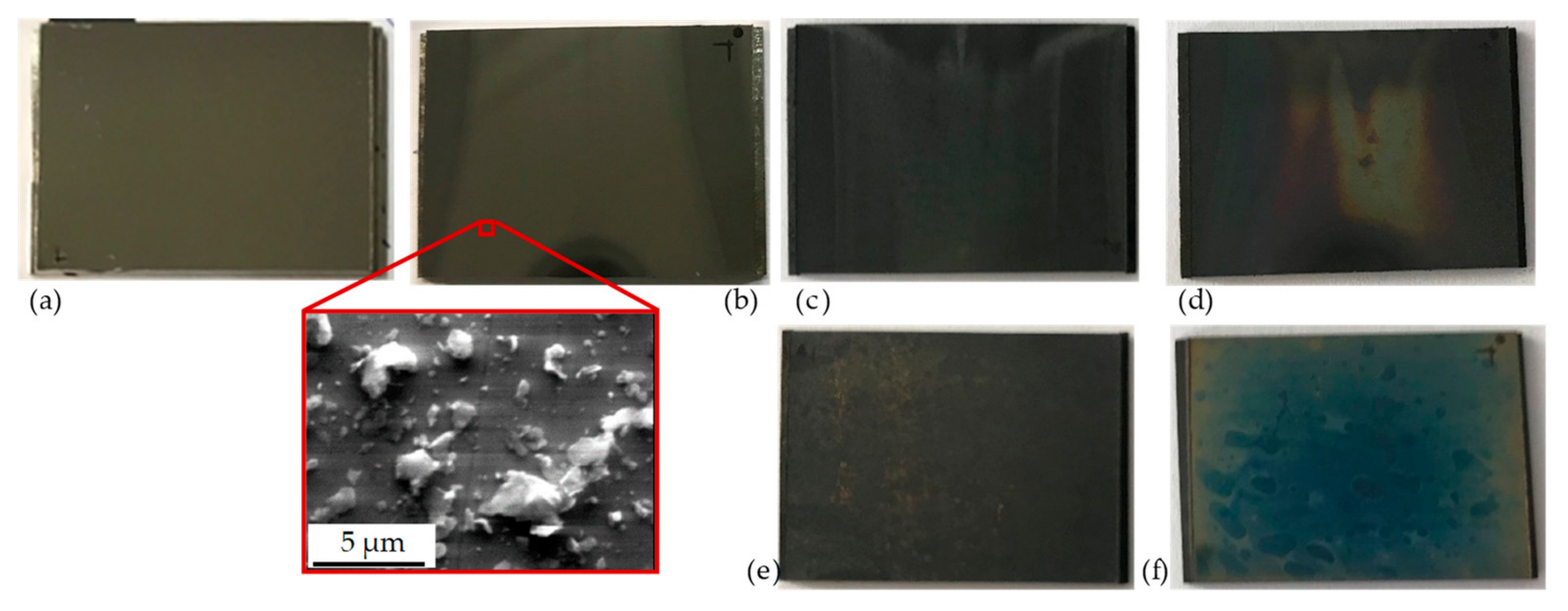
14] have shown that in addition to mechanical processes, the chemical production of graphite particles takes place; hydrogen has a notable influence on the production of graphite particles. The existing carbon dioxide reacts with hydrogen to form graphite and water vapor (i.e., chemical vapor deposition occurs). For example, graphite has been found to form and to be deposited on Inconel 617 as large particle agglomerates and as individual particles with a diameter of 0.2–1 µm [14].
Further investigations have been carried out on the formation of reaction products from the fission products that diffuse from the fuel elements. The influence of the O2 impurity is the main reason for the phase transformation from cesium to Cs2O2, which is present in solid form up to a temperature of 610 °C and also as a gas. Strontium first forms SrO2 and SrO with increasing temperature. Silver in the form of AgO remains stable at all temperature ranges. With a further increase in temperature, a turning point is reached where cesium and iodine bind [22].
With regard to the evaluation of the structural material, investigations into the influence of thermal annealing on the internal complex transformation processes have been carried out. A negative influence on the structural integrity has been confirmed by time- and temperature-dependent phase changes [23].
Taking these aspects into account, chemical and thermally-induced reactions of the base material have an indirect influence on the adhesive force, Fadh, of particles deposited on surfaces. The main influencing factor is the alteration of the material-dependent Hamaker constant, Cadh, which is necessary for the description of the force between two particles specifically in which Van der Waals forces act. It is influenced over time by the change in or interaction between particles (particle size dP), the medium between the particles and the substrate, and the substrate itself (surface condition and chemical composition). Because of chemical influence (e.g., the formation of an oxide layer), the boundary layer thickness, δ, between the particle and surface changes, i.e.,
F adh =   C adh   d P 12   δ 2
Extensive investigations on material resistance carried out over past decades have shown that oxidation phenomena occur on the corrosion-resistant alloys used in the HTR. These phenomena are achieved by the formation of layers (passivation) that are only a few micrometers thick [9].
In addition, extensive investigations have been carried out on the resistance to the reactions caused by impurities in the cooling gas helium. By varying the oxygen concentration and simulating water contamination in the cooling gas, the formation of corrosion layers on chromium-nickel-based alloys has been confirmed [20].
To date, the presence of graphite particles has been insufficiently accounted for such research. Hence, the work presented herein aims to clarify the influence of graphite particles on structural design in order to consider countermeasures within plant design, if necessary. Thus, the determination of possible reaction products and their reaction speed is essential. This forms the basis for determining the residual amounts of radionuclides that could be released in the event of mobilization of particles.

3. Methods

3.1. Materials

HTR plants that are in the approval or construction phase are estimated to be able to run for at least 60 years. Considering the high operating temperatures and the operating pressure of the coolant helium, only metallic building materials are considered for the construction of the primary circuit. As these materials come into direct contact with the hot cooling gas, corrosion- and oxidation-resistant alloys with high chromium contents are used. Alloy 800H is primarily used in the reactor and in the flow-conducting area, as well as in the graphite components. An iron-nickel-chromium-based (Fe-Ni-Cr) alloy is used in the hot gas range for some components of the core support structure as a protective sheath or guiding tube for the control rods, as an upper plenum cover for the cooling gas supply, as a thermal barrier for the lower cooling gas design, and as a hot runner lining. It is also used as a guiding tube for the superheated steam in the steam generator [24]. Alloy 800H was developed for use in the high temperature range and has a high creep and fracture strength. The alloy has already been licensed in the German HTR program for a temperature of 750 °C and a service life of up to 300,000 h [23,25].
As the second metallic material to be investigated, the chromium-nickel-based alloy, Inconel 617, was also selected. It has a higher strength than Alloy 800H at temperatures above 800 °C. It is primarily used when stable mechanical properties are required, e.g., in aircraft or classic gas turbines. Its areas of application in an HTR would be as a hot runner lining in areas with mechanical stress and as a heat exchanger tube in the medium- and high-temperature heat exchanger in the steam generator [24]. The permissible operating temperature has been determined to be 982 °C for a service life of 100,000 h in the middle heat exchanger [23]. The following table, Table 1, shows the components of the alloys.
Test samples with a wall thickness of 2 mm and an area of 30 × 22.5 mm2 (geometry was determined by the autoclave design) were exposed to a 950 °C hot particle-laden helium flow over a period of 60 s in the DRESDEN-TUBE test facility [26]. The samples were cooled from the underside. Because of the temperature gradient, graphite particles were deposited directly on the sample. A time of 60 s was sufficient to create a single particle deposition layer where individual particles were visible to determine the morphological change. Afterwards, the samples were transferred to DRESDEN-TANK for thermal annealing (Section 3.2). By selecting a suitable graphite particle distribution of the initial bed, a mean particle size distribution could be thermophoretically separated on the samples which approximately corresponds to previously published data (Figure 1). The size distributions of graphite particles were determined after decommissioning or dismantling in the AVR [5] and in the thorium high-temperature reactor (THTR) [27] in the pipe segments of the primary circuit.
The mean diameter (dP) of the particles deposited for the investigations described was found to be in the range of 2.6 and 3.2 µm, depending on the location. The test samples were provided with a single particle layer. The particle density was between 1800 and 2200 n/mm2. With this surface concentration, it is possible to investigate the geometry of individual graphite particles and to analyze the influence of thermal annealing.
Figure 2 shows the surfaces of the samples before and after coating in DRESDEN-TUBE and after thermal annealing. The thermal treatment carried out in the DRESDEN-TANK test facility is discussed in the next section.

3.2. Test Plant DRESDEN-TANK

The dust resuspension and deposition in tank geometry (DRESDEN-TANK) test plant was set up at the Technische Universität Dresden in order to investigate these processes and deepen an understanding of graphite dust behavior under HTR conditions (Figure 3).
The experiments in the test plant have focused on the investigation of the safety-relevant, long-term interactions of graphite particles on the various surfaces of the HTR (primarily the circuit components).
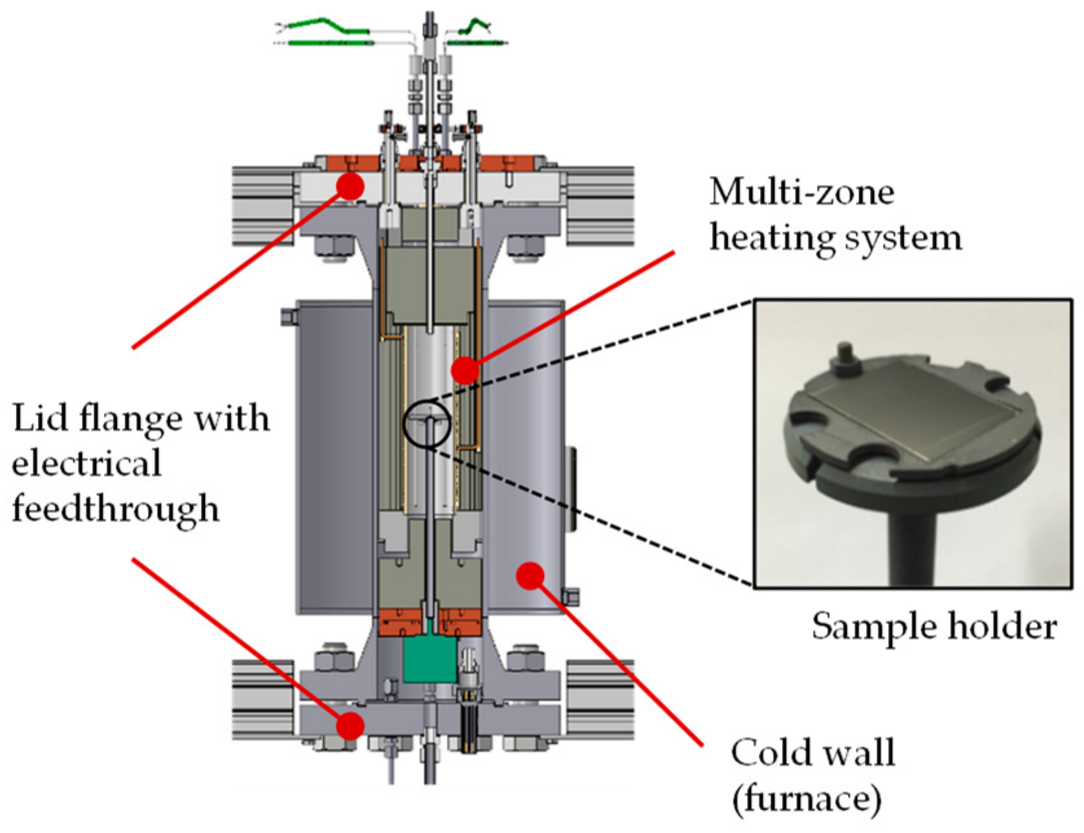
The DRESDEN-TANK test plant enables long-term tests to be carried out under representative HTR temperatures and pressures. It was designed for test durations longer than 1000 h at up to 1000 °C and 6 MPa. The overall structure and the inner specimen chamber, as well as one of the specimen grips, are shown schematically in Figure 4.
The main component of the test plant is the high-pressure temperature autoclave, which was actualized as a cold-wall furnace that can be filled with gaseous fluids. In the pressure-tight sealable sample chamber (Ø = 55 mm and height = 200 mm), substrates loaded in various states (graphitic or metallic) can be introduced and thermally annealed in various atmospheres, and can include helium, argon, nitrogen, air, or mixtures of these. The temperature can be varied within a range of 25 to 1000 °C. Controllable multi-zone heating (3 × 1 kW) ensures a stable and homogeneous temperature distribution in the area of the particle-laden sample during stationary operation. The axial temperature field is monitored by 20 thermocouples that are mounted radially between the sample holder and the inner wall over the entire height. At the same time, up to eight samples can be positioned in the center of the chamber with the help of a corresponding sample holder. In addition, axial rotation of the samples is possible in order to allow centrifugal forces to act on the particles.
The rest of the internal structure is filled with dense insulation material on the outside, which leads to savings in gas consumption during the long-term tests thanks to the reduced space requirement. The cover flanges on the top and bottom are equipped with electrical feedthroughs for heating and measuring technology.
In order to minimize any external influences during thermal treatment, accurate and contamination-free sample handling is essential. The samples are stored separately in antistatic containers and allowed to dry between each step.
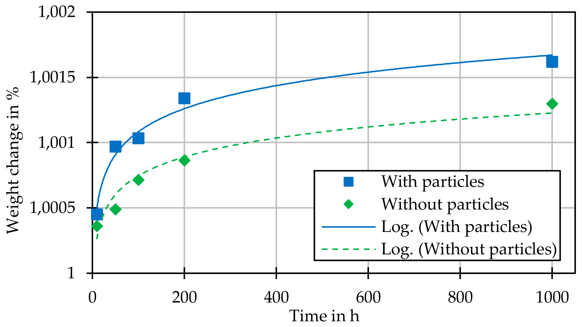
In each individual test, the change in weight of the sample and the change in the geometry of the individual particles (diameter and height) are determined.
After loading and insertion of the sample holder, the inner volume is evacuated three times to 19 Pa and rinsed with helium 5.0. At the beginning of the heating phase, the internal pressure is increased to 1 MPa. The particle-laden substrates are heated to the target temperatures at a rate of 8 k/min. After reaching the target temperature, the internal pressure is finally increased to 6 MPa. This prevents any pressure increases during heating because of gas expansions above the filling pressure limit of the system.
The experiments presented were carried out in a stable helium atmosphere (750 °C, 6 MPa) over periods of 10, 20, 50, 100, 200, 500, and 1000 h. A three-fold test repetition per test time and sample material was chosen in order to statistically confirm the statements.
With the help of the experimental data obtained here, thermally driven annealing processes such as surface carbonization or nitriding, oxidation, and changes in adhesive force can be demonstrated. Thus, the influence of a given process on the change in single particles, up to agglomerated particle accumulations, can be described in detail. In addition to the determination of the induced reaction mechanisms and speeds, the generated data have been made available for the development of scalable HTR-CFD codes and their validation.

3.3. Measurement Techniques

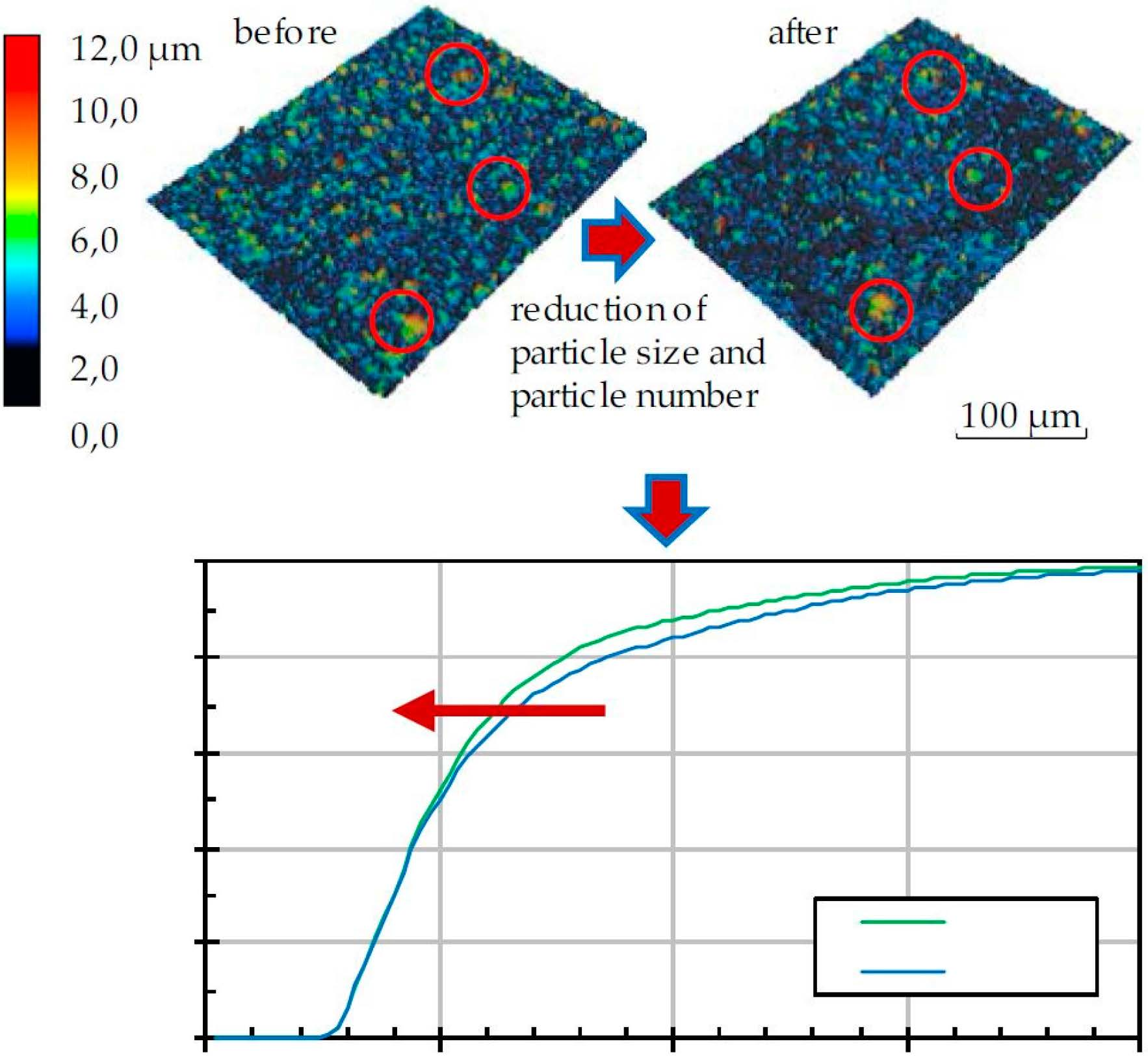
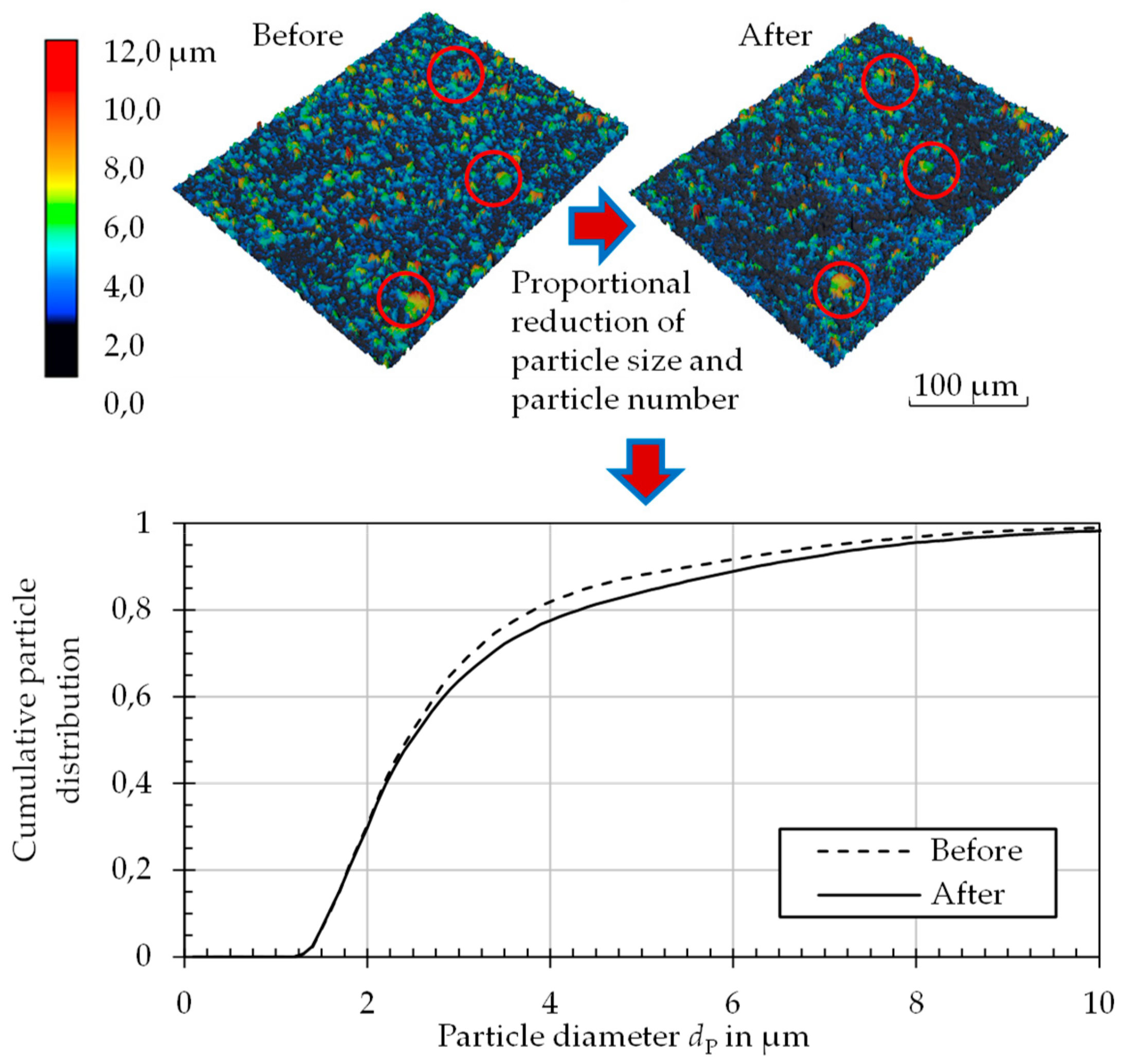
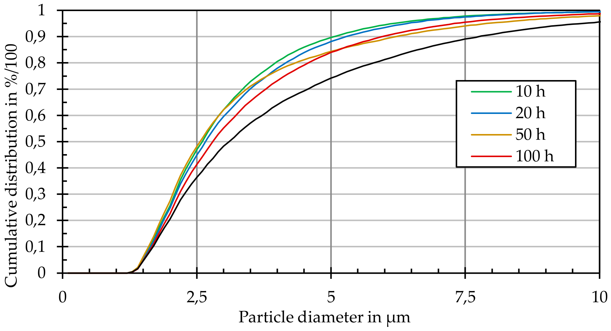
The geometric change in the particle morphology was determined by laser scanning microscopy (Keyence VK9300, Osaka, Japan). For this purpose, a height profile of each particle-laden surface was created before and after thermal annealing, and both were compared with one another; exact sample positioning makes it possible to find and measure the same particle before and after thermal annealing. Figure 5 shows this process. For each sample, 400 individual profiles with dimensions of 283 × 213 µm2 were recorded. By extrapolating these results over the entire sample area, statements could be made about the entire particle distribution within a given sample. With a maximum of 400 detected particles per profile, the geometric data of up to 100,000 particles were available for the generation of the cumulative frequency distribution of particle size. Thus, very detailed conclusions on particle size changes could be made.
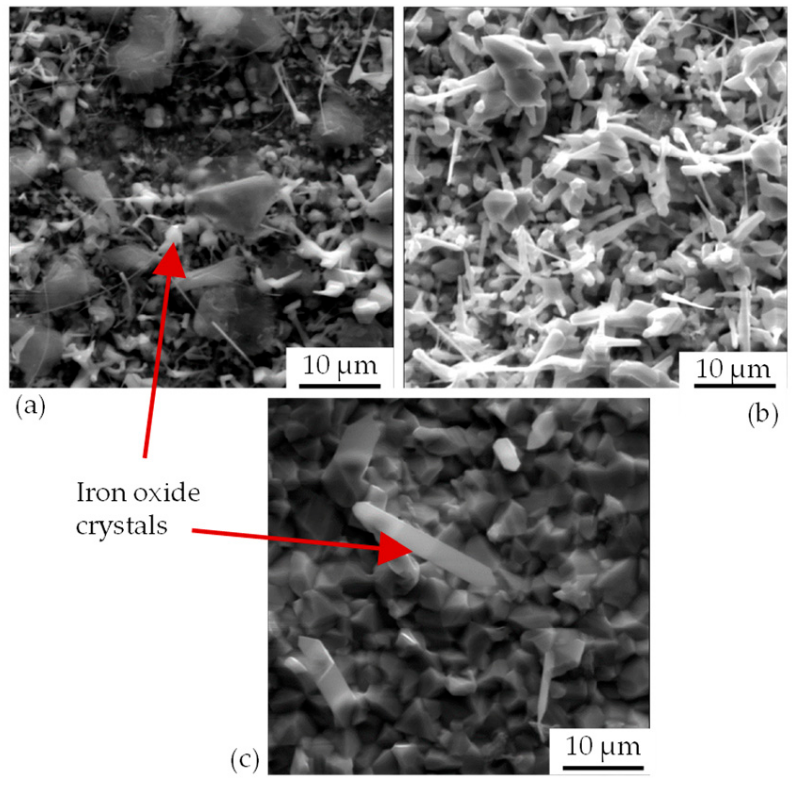
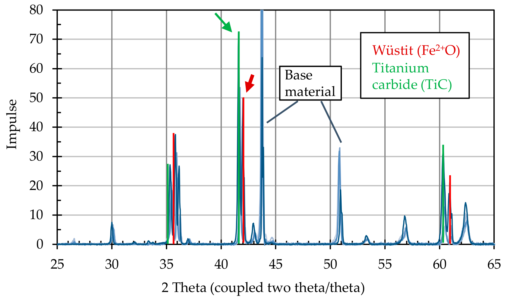
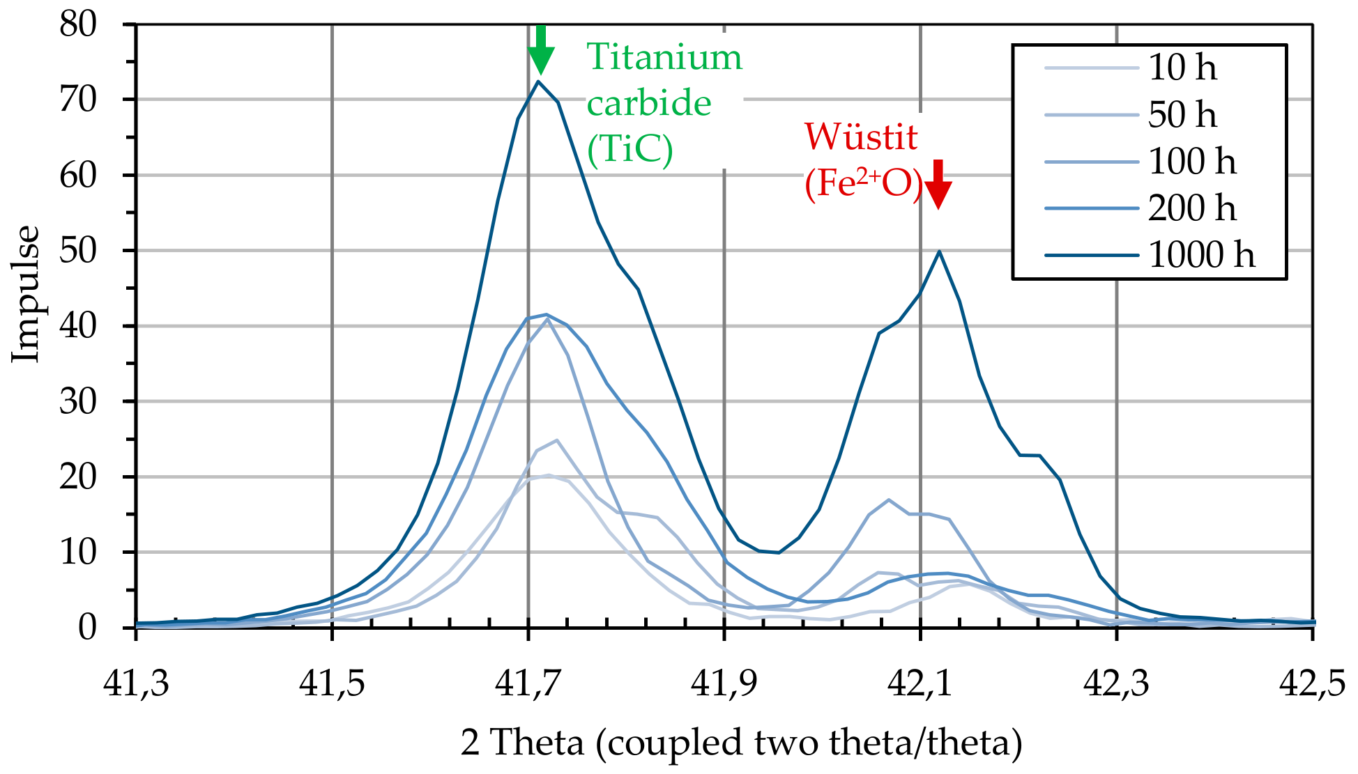
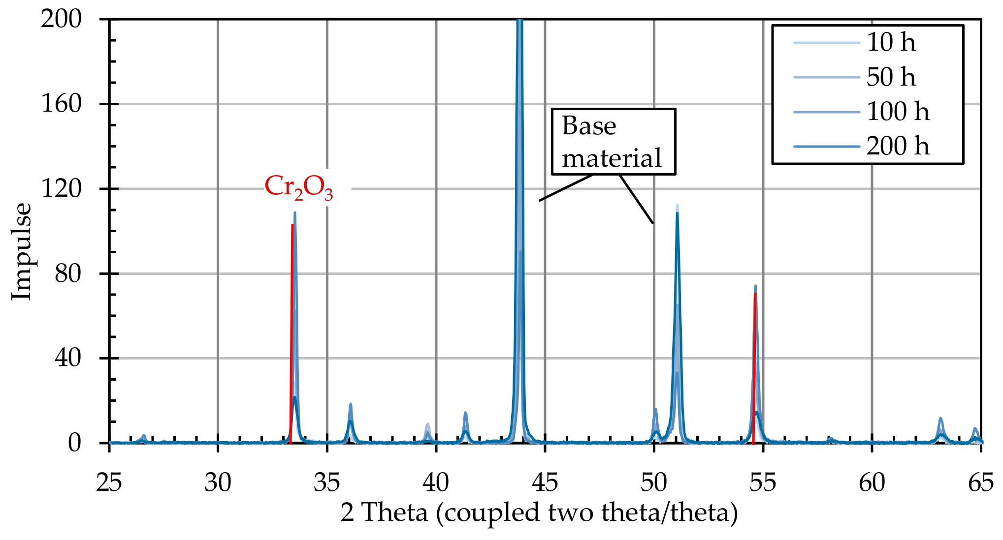
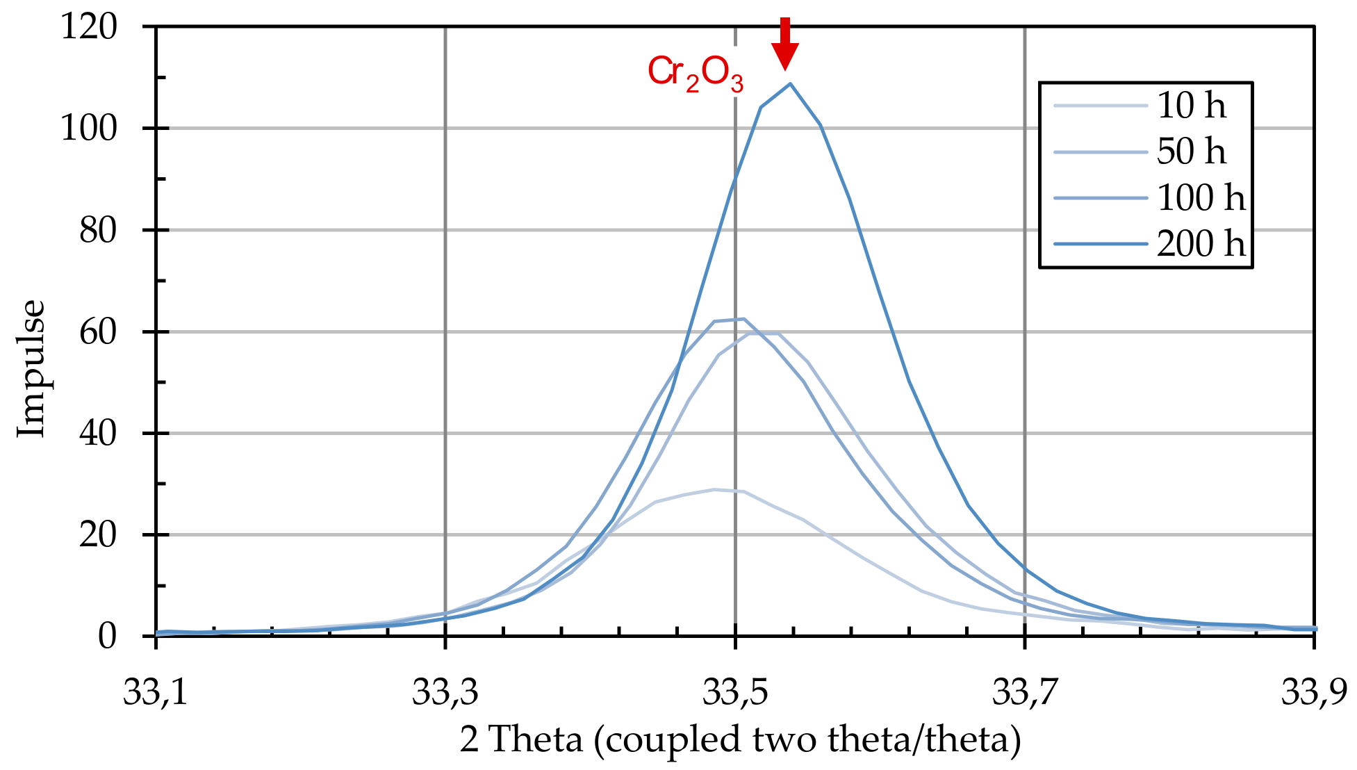
After the annealing process, the particle-laden substrates were examined for the formation of crystalline structures using X-ray diffractometric phase analysis (XRD, D8 Advance A25 Eco System, Bruker Corporation, Billerica, MA, USA). The changes induced by the presence of graphite particles were detected by comparing particle-loaded and non-loaded substrates.
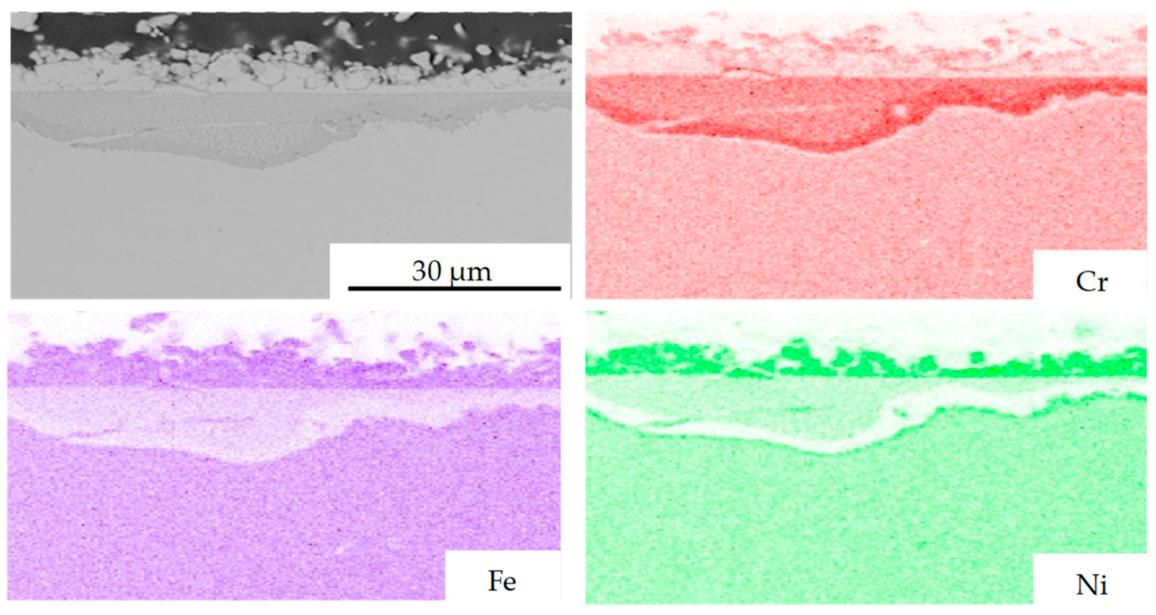
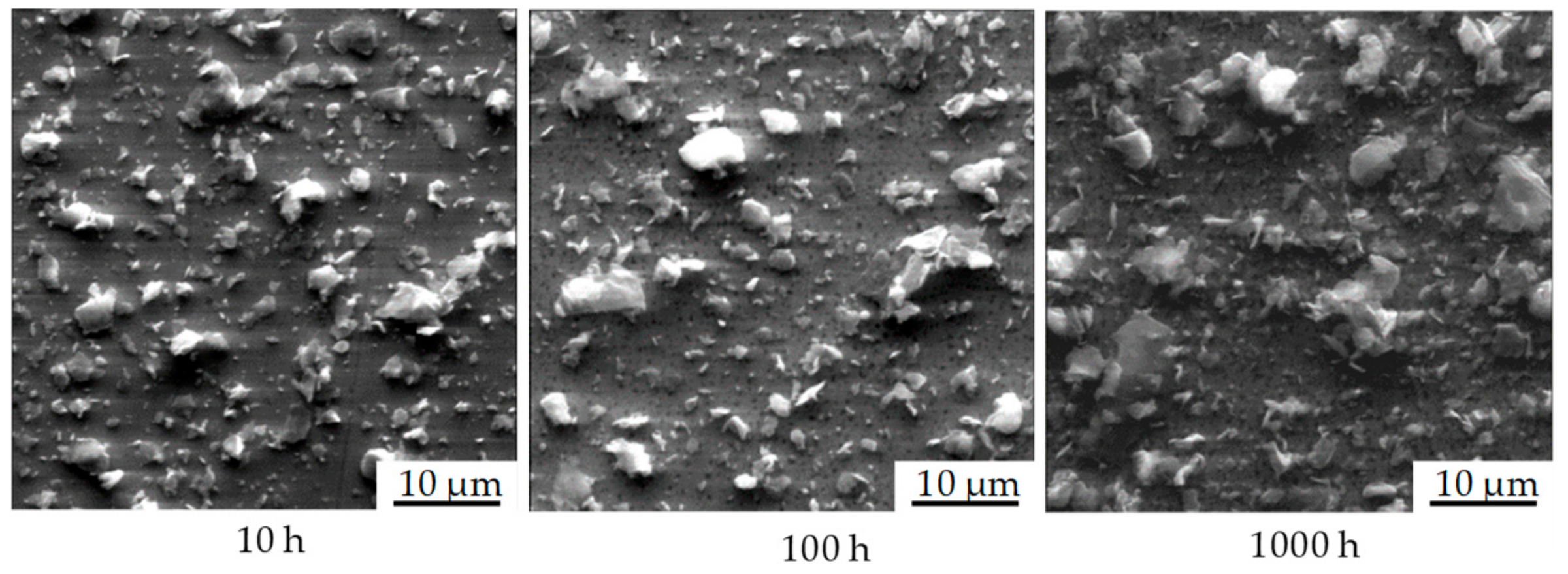
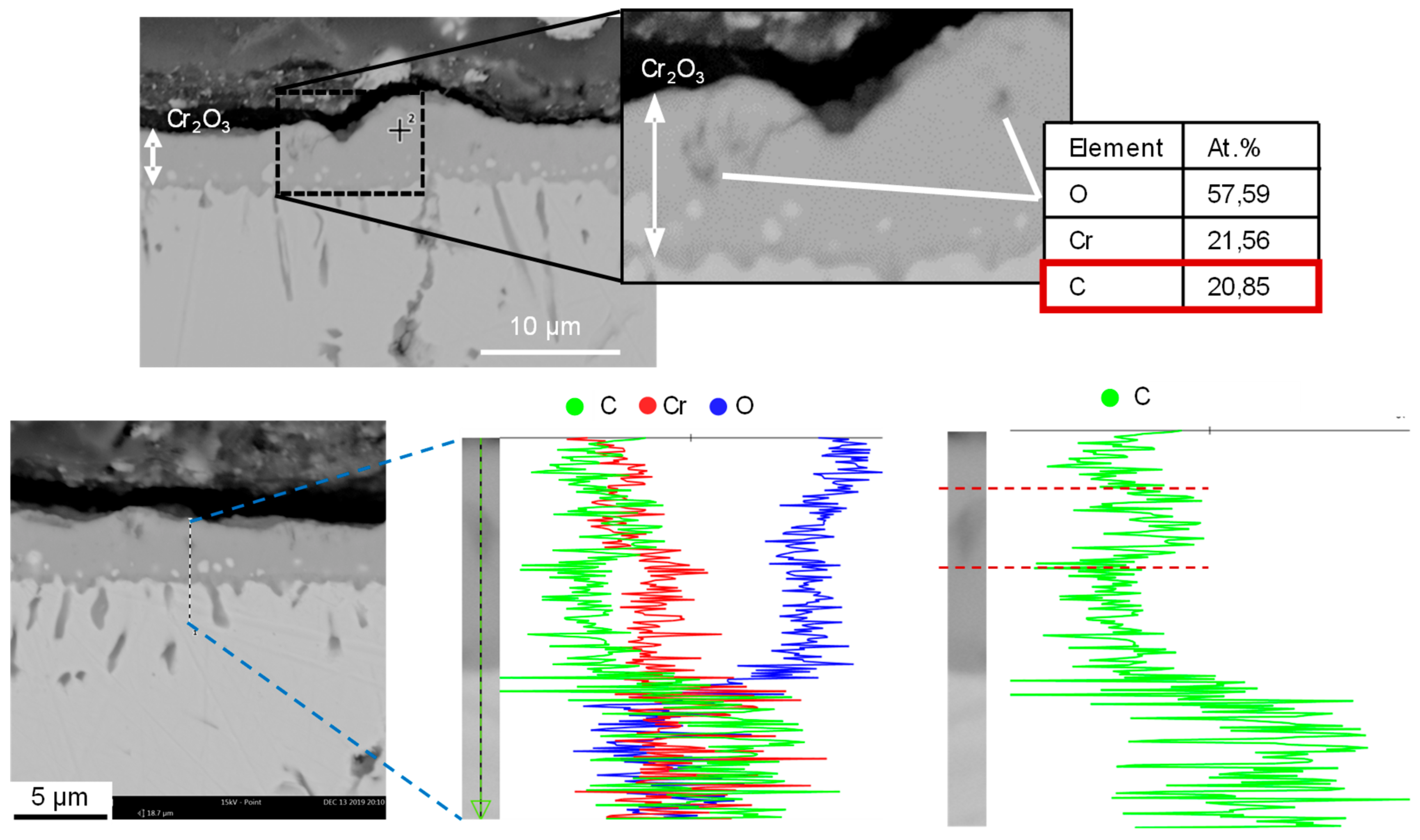
In order to describe the chemical processes on the substrate surface during thermal treatment, substrates were analyzed by means of scanning electron microscopy (SEM) and energy-dispersive element analysis (EDX). The SEM-EDX system used was Phenom Pro (LOT-QuantumDesign, Les Ulis, France). In addition, segments of substrates were embedded in epoxy resin to produce the specimens. Subsequent SEM and EDX analyses were used to investigate the surface-related material changes in cross section.
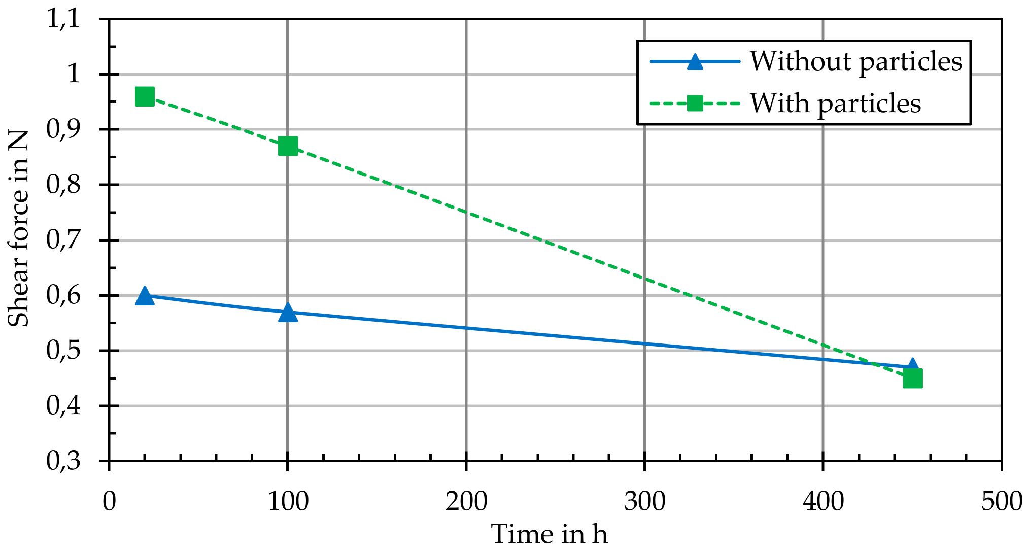
In addition, the adhesive strength of the grown layers or structures on the thermally annealed samples (with and without particle loading) was determined by means of a scratch test (performed according to DIN EN ISO 1071-3). With one measuring or scribing tip (tip radius 200 µm), five scribe marks with an increasing load were introduced to each sample and the critical force at which the grown layer detached from the substrate was determined.
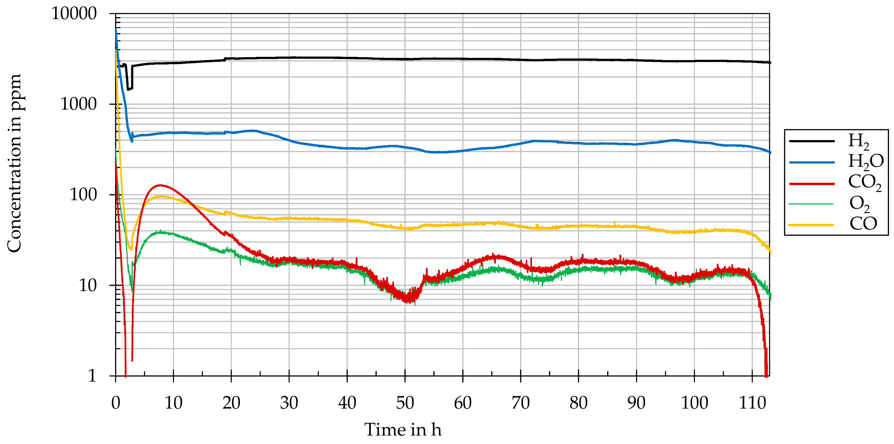
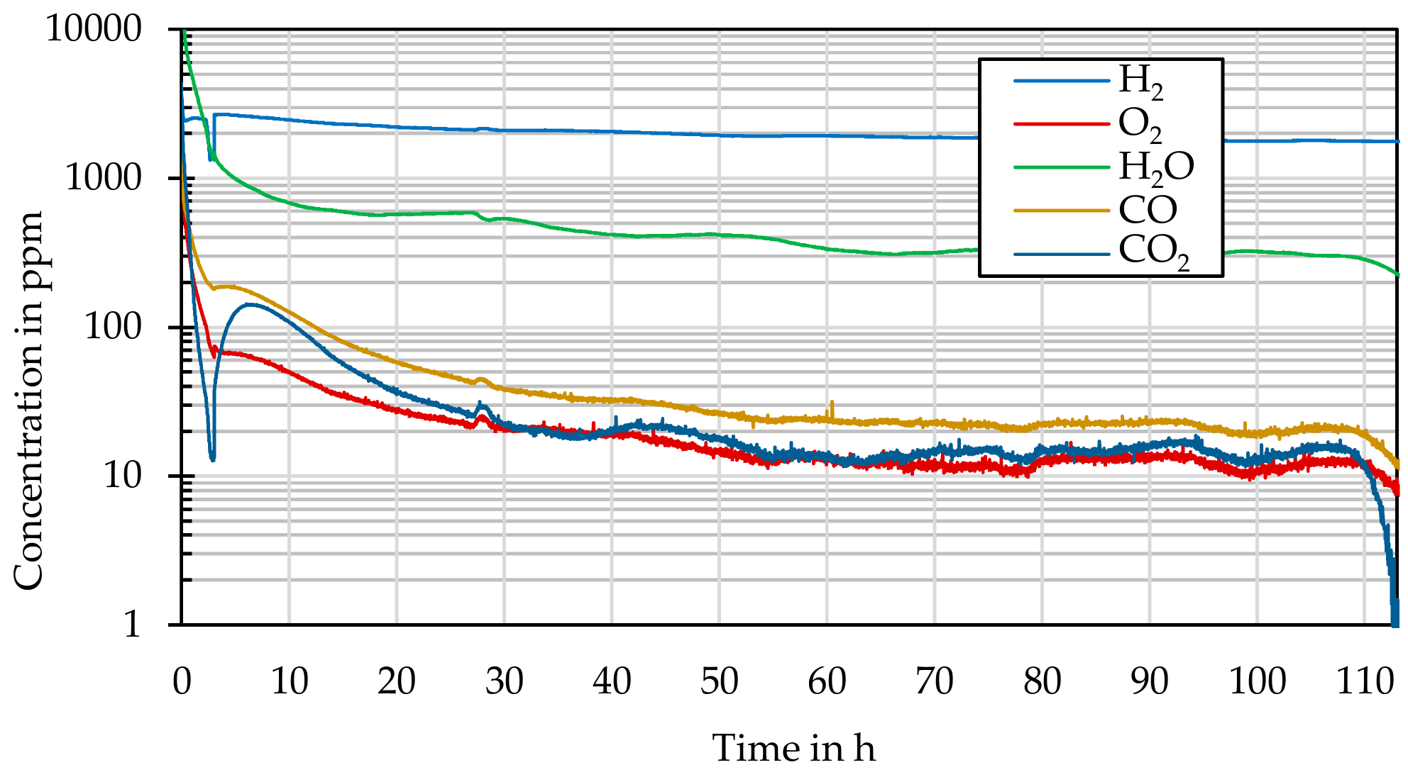
A mass spectrometer (GSD 301 O2 C, Pfeiffer Vacuum, Asslar, Germany) was used to characterize the gaseous reaction products or compounds that formed during thermal annealing as a function of time, temperature, and concentration. The concentrations of H, H2O, CO, CO2, and O2 were determined with a resolution in the single-digit part per million (ppm) range.

4. Results

The investigations revealed that the presence of graphite particles leads to changes in the metallic substrate near the surface. The results for the respective alloys are as follows.

4.1. Alloy 800H

The SEM/EDX analyses after various thermal treatments show that the surface of the iron-nickel-base alloy is subject to increased formation of needle-shaped iron oxide crystals (Figure 6). After 10 h, individual polycrystalline structures are already visible. With increasing test time, these newly formed structures grow beyond the size of the particles and the FeO layer becomes more compact. At 1000 h, individual graphite particles are no longer visible, even when using EDX element analysis, because of the height and compactness of the layer.
Diffusion processes from the structural subsoil can be seen as the reason for this. Iron diffuses from the volume of the alloy to the surface and reacts with the oxygen, which is present as an impurity in the process gas, which is helium. The length expansion of the iron oxide crystals increases parabolically up to a limit value of ~40 µm at ~200 h. It is assumed that the growth of the crystals ends because no free oxygen is available for further reactions.
In order to represent the process in the material, microsections of the samples were produced and analyzed using SEM-EDX mapping (Figure 7). A top layer can be observed to have formed on the substrate, and, at the same time, alloy constituents have become depleted in the substrate layer close to the surface, depending on the time and zone. The grown-on-top layer contains, in particular, the elements Fe and Ni, which diffuse from the substrate volume to the surface and whose concentration decreases in the near-surface layers, weakening the substrate. At the same time, chromium accumulates in this area, leading to an increase in the brittleness of the near-surface layers.
In order to describe the newly formed crystalline structure, samples with and without particle loading were analyzed simultaneously. After deduction of the ground state, iron oxide (FeO) in the phase wüstite (Fe2+O) and titanium carbide (TiC) could be detected (Figure 8). FeO is formed by the reaction of the iron with the oxygen present as an impurity, whereas TiC is formed by the reaction of the graphite particles with the titanium present in the structural material. In order to show the time-dependent growth of both compounds, two adjacent peaks are shown in Figure 9. However, several compound typical peaks are used for identification which are distributed over the entire spectrum.
Since the growth of the layer makes it impossible to purely consider the particle change, the weight change was determined for the description of the time-dependent process (Figure 10). For both substrates (with and without particle loading), a change in weight can be observed which can be described by logarithmic behavior. Figure 10 also shows that the presence of graphite particles leads to a higher weight change in the Alloy 800H substrate. The thermochemically-induced increase in the oxide layer by the previously present graphite particles can be seen as the reason for this.
The influence of the graphite particles on the layer growth, as well as on the structural change in the base material, was determined by means of the scratch test method. The adhesive force between the grown surface layer and Alloy 800H was measured (Figure 11). For particle-laden samples, the adhesive strength was reduced by 20% in the first 100 h of annealing. The structures grown on the surface, which consist of FeO, TiC, and Ni, led to a lower adhesion of the grown layer with increasing tempering time. By contrast, oxide layers on substrates without particle loading exhibited almost the same adhesive strength after 100 h of thermal annealing, but this also decreased during further annealing. This indicates intensive interactions between the graphite particles and the surrounding layer during thermal annealing. This process was confirmed by the time-dependent analysis of the gaseous reaction products.
Because of the complex chemical reactions between the substrate and the layers formed on the surface, no negligible gaseous reaction products are released. The main reaction partners are impurities in the coolant helium. The change in concentration was recorded in the ppm range and is shown in Figure 12.
Here it can be seen that at the beginning of the tempering process, when iron from the Alloy 800H substrate reacts to form iron oxide, which is deposited onto the surface, the oxygen required for this is removed from the cooling gas atmosphere. Since pure O2 is not sufficiently available for this purpose, the proportion of H2O and CO2 is also reduced (see equation in Section 2). This is confirmed by the simultaneous increase in hydrogen. After the top layer has grown accordingly and no more Fe diffuses from the structural material, saturation occurs after ~50 h. Only then is the remaining carbon degraded and do the concentrations of CO2 and H2O increase. This in turn lowers the concentration of hydrogen. It turns out that under the chosen conditions, the oxygen reacts more with Fe than with carbon or hydrogen.
According to the Boudouard equilibrium, it can be confirmed that under the existing atmospheric conditions, there is an increased CO content (in the order of ppm) compared with CO2.
On the basis of the results presented here, it is possible that during a pressure relief incident, graphite particles, and also particles of iron oxide and nickel that have formed on the metal surfaces as a result of the processes described, can become detached (Fe and Ni depletion in the subsurface, brittle chromium only still present).

4.2. Inconel 617

In comparison with the alloy Alloy 800H considered so far, individual graphite particles could still be detected on the substrate surfaces after analogous tests with the nickel-chromium-based alloy, Inconel 617. Figure 13 shows the surfaces captured by SEM. Already after 10 h, the formation of a Cr2O3 passivation layer is visible. This self-protection process of Inconel 617 under HTR conditions has already been described in detail [9,23].
With increasing test time, a reduction in the graphite particles on the surfaces can be observed. This reduced both the number and size of the individual deposited particles. Furthermore, an increased Ni concentration was detected on the surfaces by means of EDX element analysis. These Ni concentration areas correspond with the positions of the exposed particles. Accordingly, Ni enrichment took place in the graphite particles, suggesting that Ni reacts with carbon to form nickel carbides. This structural change would have an effect on the chemical composition and the adhesive strength of the particles.
An examination of the micrograph shows that no formation of intermetallic phases took place for this purpose (Figure 14). However, a time-dependent increase in the geometric dimensions of grain boundaries can be observed, as described in the literature [24]. According to EDX mapping, the Cr required for the formation of the Cr2O3 passivation layer was depleted in the near-surface structural area. It can be observed that the graphite particles formed a solid bond with the substrate. The reason for this could be the affinity of diffusion of the carbon into the material along the newly formed grain boundaries. This was confirmed by EDX point measurements. In addition, it can be observed that Ti was depleted in the near-surface grain boundaries, which again indicates the formation of TiC. It can also be observed that graphite particles were embedded in the Cr2O3 passive layer.
With increasing duration of the thermal treatment, the formation of Cr2O3 increases, growing as a brittle layer on the substrate surface. This increases the possibility of mobilization of brittle Cr2O3 surface segments.
The measurements using XRD show that the formation of the crystalline structure in the form of Cr2O3 clearly outweighs the formation of other structures (Figure 15). Figure 16 also shows the time-dependent growth of chromium oxide.
By detecting the particles present, it could be observed that the number of particles on the sample decreased by up to 10% with increasing time. This mainly concerned small particles below 2 µm. It was also shown that the geometric diameter of larger particles (>dP50) was reduced (Figure 17). In addition to embedding in the passivation layer and diffusion into the boundary layer, the conversion of graphite to CO or CO2 can be seen as the reason for particle reduction.
When determining the adhesive force, the influence of the growing Cr2O3 layer on the hardness of the layer described above was demonstrated (Figure 18). In samples with particle loading, a clear and continuous reduction of the adhesive strength can be observed, as the grown Cr2O3 layer became more porous and cracked with increasing annealing time. Conversely, the adhesive strength of samples without particle loading hardly decreased. The reason for this can be considered to be the influence of graphite particles on the diffusion process of the components of the Cr2O3 layer from the base material.
A comparison of particle-laden tempered substrates shows that the surface layer formed on Alloy 800 H has a higher scratch hardness than that on Inconel 617.
As already shown in the evaluation of the XRD images, the formation of chromium oxide superimposes all other processes. The oxygen required for this formation is extracted almost continuously from all existing compounds under the existing pressure and temperature conditions (Figure 19).
An approximate saturation of the layer formation can also be seen here in the reduced supply of Cr with increasing height of the passivation layer. The reduced oxygen supply slows down the vertical spread of the Cr2O3 layer.
The investigation of the interactions of graphite particles with Inconel 617 showed that the growth of a porous Cr2O3 layer (self-protection function of the alloy) was almost completed in the first 50–100 h, since hardly any oxygen is available for further formation. The graphite particles grew into the crystalline structure and were fixed there. Pores and cracks were present in the forming layer which increased the probability that segments of the Cr2O3 layer would detach.

5. Conclusions

The investigations presented here have shown that chemical interactions have a main impact on the changes in particle size and composition. Thermally-induced processes have a significant negative influence on the near-surface area of metallic components (several µm into the material) in the primary circuit of a helium-cooled high-temperature reactor.
The investigations into Alloy 800H showed that the presence of graphite particles causes the formation of a crystalline iron oxide layer along with the formation of inner-metallic phases in the substrate as a function of time. It was observed that on the surface of thermally treated samples (up to 1000 h) some crystals grew up to 40 µm in length. These were identified as iron oxide (mineral form wüstite). These cause stratification with different concentrations of alloy constituents in the layer near the surface. Thermal diffusion leads to the depletion of iron (Fe) and nickel (Ni). The associated local increase in the concentration of brittle Cr leads to a weakening of the surface structure and can result in the mobilization of metallic segments. Furthermore, the Fe diffused to the surface is seen as a source for the formation of Fe2+O crystals on the particle-laden substrate surfaces. A comparison of the thermally annealed substrates with samples without graphite particle loading confirmed the driving influence of the graphite particles on the thermochemical formation of a new polycrystalline surface structure. It was shown that the adhesion of the surface was reduced by 20% in the first 100 h of annealing due to layer growth in particle-loaded samples.
The oxygen present in the helium coolant was the main cause of the formation of a Cr2O3 passivation layer on Inconel 617. Furthermore, it became clear that thermal annealing caused the remaining particles to react with the metallic surface, in addition to particle reduction. During the evaluation of the remaining particles it could be observed that the number of particles on the sample decreased by up to 10% with increasing time. This led to a strong bond between both components. At the investigated temperature and pressure range, the diffusion of carbon into the base material can be seen as the reason for this bonding effect. The evaluation of the gaseous reaction products confirmed that the reaction of carbon to CO also contributes to the observed particle reduction. Mass spectrometry confirmed the time-dependent formation of CO and CO2 in the helium atmosphere during thermal annealing. Furthermore, the investigations of the particle-laden substrate surfaces show nickels affinity to diffuse from the substrate volume into the near-surface layer, as well as into the graphite particles. It was observed that with increasing time the adhesion between the new layer and the base material decreased significantly. This increased the possibility of mobilizing Cr2O3 surface segments on flow-guiding components consisting of Inconel 617.
In summary, it can be stated that the chemical reactions of graphite particles with metallic alloys used during thermal annealing lead to a reduction in adhesive strength. It should be investigated whether a thermally stable protective layer can be used for flow-carrying areas. This could be used to prevent the mobilization of metallic segments. Flaking, as well as the mobilization of sections of the boundary layer that likely absorb radioactive fission products (because the cooling gas flow is radioactively contaminated), can no longer be excluded in long-term operations or during load changes (change of the primary flow velocities). It is recommended to investigate how the segments could flake off in an event of a pressure relief accident.
Our investigations will be completed with further experiments where the pressure of the helium atmosphere is varied in order to investigate the influence of particle–wall interaction in areas of the HTR with high flow velocities.

Author Contributions

Conceptualization, A.A. and M.H.; methodology, A.A.; formal analysis and investigation, A.A.; resources, F.F.; writing—original draft preparation, A.A.; writing—review and editing, A.A., M.H., and W.L.; supervision, M.H.; project administration, M.H. and W.L.; funding acquisition, A.H. All authors have read and agreed to the published version of the manuscript.

Funding

This work was funded by the German Federal Ministry for Economic Affairs and Energy (BMWi) with the grant number 1501526 on the basis of a decision by the German Bundestag. We acknowledge the support of the Open Access Publication Funds of the SLUB/TU Dresden.

Acknowledgments

The authors acknowledge Erik Findeisen for assistance with sample preparation.

Conflicts of Interest

The authors declare no conflict of interest. The funders had no role in the design of the study; in the collection, analyses, or interpretation of data; in the writing of the manuscript, or in the decision to publish the results.

References

  1. Wei, X.; Jun, S.; Yanhua, Z.; Lei, S. The influence of nuclear graphite oxidation on air ingress accident of HTR-PM. Ann. Nucl. Energy 2017, 110, 1242–1248. [Google Scholar] [CrossRef]
  2. Wrochna, G.; Sobolewski, J. Possibilities for Deployment of High-Temperature Nuclear Reactors in Poland: Report of the Committee for Analysis and Preparation of Conditions for Deployment of High-Temperature Nuclear Reactors; Ministry of Energy: Warsaw, Poland, 2017.
  3. Irwanto, D.; Permana, S.; Pramutadi, A.; Pramuditya, S. Preliminary Design Study of Small Power 30-50 MWt Experiment Power Reactor based on High Temperature Pebble Bed Gas Cooled Reactor Technology. J. Phys. Conf. Ser. 2019, 1127, 012024. [Google Scholar] [CrossRef] [Green Version]
  4. Po, L.C.C. A PC-based high temperature gas reactor simulator for Indonesian conceptual HTR reactor basic training. J. Phys. Conf. Ser. 2018, 1013, 012183. [Google Scholar]
  5. Von der Decken, C.-B.; Wawrzik, U. AVR—20 Jahre Betrieb: Ein Deutscher Beitrag zu Einer Zukunftsweisenden Energietechnik. In Proceedings of the Tagung Aachen, Aachen, Germany, 17–18 May 1989; VDI: Düsseldorf, Germany, 1989. [Google Scholar]
  6. Peng, W.; Chen, T.; Sun, Q.; Wang, J.; Yu, S. Preliminary experiment design of graphite dust emission measurement under accident conditions for HTGR. Nucl. Eng. Des. 2017, 316, 218–227. [Google Scholar] [CrossRef]
  7. Humrickhouse, P.W. HTGR Dust Safety Issues and Needs for Research and Development: Next Generation Nuclear Plant Project; INL/EXT-11-21097; Idaho National Laboratory: Idaho Falls, ID, USA, 2011.
  8. Xiaowei, L.; Sheng, X.-Y.; Yu, S.-Y.; He, S.-Y. Wear behavior of graphite IG-11 in different gas environments. Mocaxue Xuebao/Tribol. 2005, 25, 173–177. [Google Scholar]
  9. Kissane, M. A review of radionuclide behaviour in the primary system of a very-high-temperature reactor. Nucl. Eng. Des. 2009, 239, 3076–3091. [Google Scholar] [CrossRef]
  10. Moormann, R. Fission Product Transport and Source Terms in HTRs: Experience from AVR Pebble Bed Reactor. Sci. Technol. Nucl. Install. 2008, 2008, 1–14. [Google Scholar] [CrossRef] [Green Version]
  11. Xie, F.; Cao, J.; Feng, X.; Liu, X.; Tong, J.; Wang, H.; Dong, Y.; Zhang, Z.; Loyalka, S. Experimental research on the radioactive dust in the primary loop of HTR-10. Nucl. Eng. Des. 2017, 324, 372–378. [Google Scholar] [CrossRef]
  12. Stempniewicz, M.M.; Winters, L.; Caspersson, S.A. Analysis of Dust and Fission Proucts in a Pebble Bed NGNP. In Proceedings of the 5th International Topical Meeting on High Temperatur Reactor Technology (HTR2010), Prague, Czech Republic, 18–20 October 2010. [Google Scholar]
  13. Herranz, L.E.; del Prá, C.L.; Dehbi, A. Major Challenges to Modeling Aerosol Retention Near a Tube Breach During Steam Generator Tube Rupture Sequences. Nucl. Technol. 2017, 1, 83–93. [Google Scholar] [CrossRef]
  14. Meng, Y.; Yin, H.; Liu, M.; Ma, T.; Jiang, S. Experimental study on the generation of carbonaceous dust formed by chemical vapor deposition in HTGR. Nucl. Eng. Des. 2018, 335, 172–177. [Google Scholar] [CrossRef]
  15. Stempniewicz, M.; Winters, L.; Caspersson, S. Analysis of dust and fission products in a pebble bed NGNP. Nucl. Eng. Des. 2012, 251, 433–442. [Google Scholar] [CrossRef]
  16. Lustfeld, M.; Qu, T.; Lippmann, W.; Hurtado, A.; Göhler, D. Experimental study of graphite particle deposition upstream of a forward-facing step. Nucl. Eng. Des. 2014, 271, 552–559. [Google Scholar] [CrossRef]
  17. Beck, J.M.; Pincock, L.F. High Temperature Gas-Cooled Reactors Lessons Learned Applicable to the Next Generation Nuclear Plant: Next Generation Nuclear Plant Project; INL/EXT-10-19329; Idaho National Laboratory: Idaho Falls, ID, USA, 2011.
  18. Sandell, L. A Review of Radionuclide Release from HTGR Cores During Normal Operation: Final Report; General Atomics: Palo Alto, CA, USA, 2004; p. 1009382. [Google Scholar]
  19. Housiadas, C.; Kissane, M.; Sehgal, R. Fission Product Release and Transport. Nuclear Saf. Light Water Reactors 2012, 425–517. [Google Scholar] [CrossRef]
  20. Tsai, C.J.; Yeh, T.K.; Wang, M.Y. High Temperature Behavior of Candidate Alloys in Helium Environments. In Proceedings of the EUROCORR 2015, European Corrosion Congress, Graz, Austria, 6–10 September 2015. [Google Scholar]
  21. Kelly, B.T.; Marsden, B.J.; Hall, K.; Martin, D.G.; Harper, A.; Blanchard, A. Irradiation Damage in Graphite Due to Fast Neutrons in Fission and Fusion Systems: Appendix 2. IAEA Tecdoc. 2000, 1154, 207–213. [Google Scholar]
  22. Li, C.; Zhang, J.; Fang, C. Chemical Forms of Important Fission Products in the Primary Circuit of HTR-PM Under the Condition of Equilibrium Core: From Methodology to Preliminary Results. Nucl. Technol. 2017, 200, 45–53. [Google Scholar] [CrossRef]
  23. Wright, R.; Wright, J.; Cabet, C. Material Performance in Helium-Cooled Systems. In Comprehensive Nuclear Materials; Elsevier: Amsterdam, The Netherlands, 2012; pp. 251–277. ISBN 978-0-08-056033-5. [Google Scholar]
  24. High Temperature Materials White Paper: Next Generation Nuclear Plant Project; INL/EXT-09-17187; NGNP, Idaho National Laboratory: Idaho Falls, ID, USA, 2012.
  25. Bodmann, E. High Temperature Metallic Materials for Gas-cooled Reactors. In Proceedings of the Specialists Meeting, Cracow, Poland, 20–23 June 1988. [Google Scholar]
  26. Fischer, F.; Andris, A.; Lippmann, W.; Hurtado, A. Particle Deposition by Thermophoresis Under High-Temperature Conditions in a Helium Flow. J. Nucl. Eng. Radiat. Sci. 2018, 4, 041020. [Google Scholar] [CrossRef]
  27. Rott, H.P.; Wahsweiler, H.G. Abschlussbericht zum Vorhaben Auswertung von Inbetriebnahmeergebnissen am THTR-300 für HTR Nachfolgeanlagen: Teilvorhaben 6.1: Verteilung und Auswirkung von Graphitstaub im Primärkreis; Report No. RA 5898; Hochtemperaturbau GmbH: Mannheim, Germany, 1990. [Google Scholar]
Figure 1. Cumulative particle size distribution of dust.
Metals 10 00140 g001
Figure 2. Substrate before coating in DRESDEN-TUBE (a), before (b) and after thermal annealing in the DRESDEN-TANK for 100 h at 750 °C, 6 MPa helium; with particles: (c) Alloy 800H, (d) Inconel 617; without particles: (e) Alloy 800H, (f) Inconel 617.
Metals 10 00140 g002
Figure 3. Current setup of the test plant DRESDEN-TANK.
Metals 10 00140 g003
Figure 4. Structural design of the high-pressure autoclaves and design of the sample holder.
Metals 10 00140 g004
Figure 5. Inconel 617 loaded with graphite dust and thermally annealed for 200 h at 750 °C (6 MPa helium).
Metals 10 00140 g005
Figure 6. SEM plan-view micrographs of particle-loaded sample Alloy 800H at 750 °C and 6 MPa helium, annealed thermally: (a) 10, (b) 100, and (c) 1000 h.
Metals 10 00140 g006
Figure 7. SEM cross section of Alloy 800H (100 h, 750 °C, 6 MPa helium) formation of layers in the substrate by diffusion of elements (Cr, Fe, and Ni).
Metals 10 00140 g007
Figure 8. XRD measurement of Alloy 800H with the identification of the decisive compounds (Fe2+O and TiC).
Metals 10 00140 g008
Figure 9. XRD measurement of Alloy 800H with enlarged representation of the decisive connections.
Metals 10 00140 g009
Figure 10. Influence of the graphite particles on the weight of the sample.
Metals 10 00140 g010
Figure 11. Determination of the bond hardness between substrate and layer.
Metals 10 00140 g011
Figure 12. Representation of gaseous reaction products and impurities in the cooling gas helium during thermal annealing of Alloy 800H.
Metals 10 00140 g012
Figure 13. SEM plan-view micrographs of particle-loaded sample Inconel 617 at 750 °C, 6 MPa helium, and up to 1000 h annealed thermally.
Metals 10 00140 g013
Figure 14. SEM cross section for Inconel 617 thermal annealing in DRESDEN-TANK: 100 h, 750 °C, 6 MPa helium.
Metals 10 00140 g014
Figure 15. XRD measurement of Inconel 617 with identification of the decisive compounds (Cr2O3, base material).
Metals 10 00140 g015
Figure 16. XRD measurement of Inconel 617 with enlarged representation of the decisive connections.
Metals 10 00140 g016
Figure 17. Change in the visible particle diameter in the period up to 1000 h.
Metals 10 00140 g017
Figure 18. Determination of the bond hardness between the substrate and layer.
Metals 10 00140 g018
Figure 19. Representation of gaseous reaction products and impurities (H2, O2, H2O, CO, and CO2) in the cooling gas helium during thermal annealing of Inconel 617.
Metals 10 00140 g019
Table 1. Chemical composition of the alloys investigated, in percentages (%) [23].
NiFeCrMoAlTiCSiCu
Alloy 800H30–3243.719–22-0.2–0.40.2–0.50.080.2–0.70.5
Inconel 61748220–2311–148.5–100.2–0.60.05–0.10.20.5

