Review

Corrosion Behaviors of Selective Laser Melted Aluminum Alloys: A Review

1
School of Mechanical Engineering, Shanghai Jiao Tong University, Shanghai 200240, China
2
School of Materials Science and Engineering, Central South University, Changsha 410083, China
3
School of Materials, University of Manchester, Manchester M13 9PL, UK
4
Department of Engineering, University of Cambridge, Cambridge CB3 0FS, UK
*
Author to whom correspondence should be addressed.
Hongwei Chen and Chaoqun Zhang contribute equally to this paper.
Metals 2020, 10(1), 102; https://doi.org/10.3390/met10010102
Submission received: 27 November 2019 / Revised: 21 December 2019 / Accepted: 4 January 2020 / Published: 9 January 2020
(This article belongs to the Special Issue Additive Manufacturing of Metals with Lasers)

Abstract

:
Selective laser melting (SLM) is an ideal method to directly fabricate products with high geometrical complexity. With low density and good corrosion resistance, aluminum alloys are widely used as important structural materials. Microstructures and mechanical properties of SLMed aluminum alloys have been recently widely studied. Corrosion behavior as a vital concern during the service of SLMed aluminum alloy parts has also drawn many attentions. Previous studies have found that SLM-processed aluminum alloys exhibit better corrosion resistance compared to the casted and wrought counterparts for both Al-Si alloys and high strength 2xxx Al alloys, which is mainly due to the unique microstructure features of SLMed Al alloys. For Al-Si alloys, with different shapes of Si networks, the different building planes show discrepant corrosion behaviors. Owing to the rougher surface with relatively larger numbers of defects, the as-printed surface is vulnerable to corrosion than the polished. Heat treatment has a negative effect on corrosion resistance due to the breakup of Si networks. The microstructure features correlated with the corrosion behaviors were also reviewed in this paper. Some suggestions on the future study of corrosion behaviors of SLMed Al alloys were put forward.

1. Introduction

Growing attention has been paid to 3D printing due to the significant advantages it offers in manufacturing products with complex structures without extra machining processes [1,2,3]. As 3D printing can produce components with complex geometries, which are needed in many industries, it is widely used to produce various metallic parts, made from different metals, including aluminum alloys [4], titanium alloys [5,6], steels [7,8,9], nickel alloys [10,11] and shape memory alloys, [10,12]. Mehrpouya et al. summarized in their review that 3D printing exhibits enormous market potential in industry 4.0 due to its significant advantages, such as time and materials saving and high design freedom [13]. Selective laser melting (SLM) is one of the most promising 3D printing methods mainly used to manufacture metal products by selectively melting the layers composed of metal powders [14,15,16]. SLM process is widely used to produce aluminum parts [4], titanium parts [5,6], biomedical parts [17], steels parts [7,8,9] and so on [18].
SLM is developed from the selective laser sintering (SLS) process. According to the schematic diagram presented in Figure 1, it is clear that SLM employs a laser beam with high power (200 W) to thoroughly melt the selected area in each powders layer that is designed by the matching software [19,20,21,22]. The protective atmosphere, including nitrogen, is utilized to avoid the oxide of molten metal [23,24,25]. After the metal powders are melt and solidify, the building cylinder moves down the pre-set distance, then the recoating device prepares a new powders layer on the lower layer and the laser beam starts to work again [26,27]. This building process will continue until the components are entirely built [28].
Due to the outstanding advantages of SLM products such as building flexibility and raw materials saving compared to the traditional casting process, it is promising to produce metal components regardless of geometrical complexity through SLM process [1,2,29]. As the metal powders in the selected area are entirely melted and solidify rapidly during processing [30,31], corresponding components produced by SLM have high density, good surface quality and ideal dimensional accuracy compared to other 3D printing methods such as SLS [32]. Furthermore, the refined microstructure resulted from the rapid solidification rate can significantly improve the mechanical properties [33,34].
However, supporting structure requirement and low building rate during manufacturing restrict the application of the SLM process. The quality of the SLM prepared alloys depend on the process parameters, such as the power of the laser, hatch distance and powder layer thickness, scanning speed and especially the composition of the powders [16,35,36,37]. It is reported that addition of 4 wt. % Si can significantly refined grains and produced SLM AA7075 alloys without crack [38]. Kairy et al. found icosahedral quasicrystal that unreported previously in SLM prepared AA7075 aluminum alloy [39]. Besides, the surface treatment and the machining process are demanded to meet the industrial requirement [40]. The high-temperature gradient (3500 K/s)also causes different shrinkage and introduces residual stress into the structure [41]. The existence of residual stress is detrimental to the mechanical properties and leads to thermal distortion, especially in the thin-walled parts [16,42,43]. Hence, it is inevitable to use proper heat treatment method to relieve the residual stress. However, the microstructure is also changed after post heat treatment as well as the mechanical properties and the corrosion resistance [44,45].
With the small melting pool and relatively shallow melting depth, the rapid cooling and solidification rates (103–106 K/s) of SLM lead to the formation of ultrafine microstructure compared to the conventional casting process [32,46,47,48]. For the Al-Si series alloys produced by SLM, microstructure presents the typical morphology that α-Al matrix is implanted into the continuous Si networks, while the casted alloy is the coarser microstructure with acicular Si phase [49,50]. Because of the large temperature gradient, the sizes of cellular structures gradually grow with the increasing distance away from the center of the melt pool [51,52,53]. Due to the non-equilibrium state after SLM process, an post heat treatment that is applied to the adjustment of mechanical properties has a significant influence on the microstructure evolution of the SLM-produced alloy, for example, the Si networks of the SLM Al-Si series alloys turn into the Si particles after heat treatment [52,54,55,56,57]. The processing parameters also have an important effect on the formation of structures; improper parameters result in cracking, pores or other defects in the products during SLM [23,25,36,58].
Corrosion resistance in various working environments is an important property for metallic material components. The poor corrosion resistance severely restricts the application ranges and causes enormous economic costs and even results in the life-threatening accidents in some cases [59,60,61]. With the low density, high specific strength and good corrosion resistance compared to steels, aluminum alloys have been widely applied in aerospace engineering and automobile industry [48,62]. The study on SLM prepared aluminum alloys has been growingly reported in recent years. Meanwhile, the corrosion behaviors of SLM-produced aluminum alloys gained growing attentions [63,64,65]. With distinctly different microstructure and alloying elements distribution in the matrix, SLM aluminum alloys show different corrosion behaviors compared to the casted Al alloy [63,64,65]. The corrosion behaviors vary with the sizes of cellular morphology, such as the melt pool borders, having the largest cellular structure among the printed surface [66,67,68]. The working places, such as in the wet environment or corrosive seawater environment that facilitate corrosion reaction, have a significantly negative impact on the corrosion resistance of SLM alloys [69]. So, it is vital to research the corrosion behaviors of SLM-produced aluminum alloys components. On the other hand, appropriate post heat treatment is used to relieve the residual stress in SLM prepared products through microstructure adjustment [16,42,54,70]. It is essential to study the evolution of corrosion resistance which is closely related to the microstructure. Before the adoption of appropriate additional surface treatment or other corrosion protection methods to improve the corrosion resistance aluminum alloys after SLM process, the corrosion mechanism should be detected.
The microstructure characteristics, mechanical properties and the effect of post heat treatment on microstructure andproperties of SLM prepared Al-Si alloys were summarized in detail by Song et al. [71]. Sander et al. and Kong et al. summarized the influence of commmon issues (pores, surface roughness and anisotropy) on the corrosion of SLM prepared alloys and made a brief investigation about SLM produced aluminum alloys, they also summarized the studies related to the corrosion behaviors of aluminum alloys produced by additive manufacturing process [72,73]. The corrosion behaviors of several types of SLM prepared Al-Si alloys are already investigated by researchers. In order to further understand the research progress of SLM produced aluminum alloys in corrosion resistance, this paper mainly describes the influence of post heat treatment on microstructure evolution and corrosion resistance of SLM-produced Al-Si alloys. Part two summarizes the microstructure evolution, while the corrosion behaviors are presented in the third part. The summary and outlook of SLM aluminum alloys on corrosion resistance study is described in the last part.

2. Microstructure of Al Alloys after SLM

2.1. In as-Built State

Due to the near eutectic composition and relatively lower thermal expansion coefficient (19.4 × 10⁻⁶ °C−1, compared to other non Al-Si alloys, such as 2xxx and 7xxx Al alloys), Al-Si alloys are the most frequently used aluminum alloys for SLM [2,26]. Existing literatures on corrosion behaviors of SLM prepared aluminum alloys mainly focus on Si-containing aluminum alloys, such as AlSi10Mg and Al-12Si. A few studies have been devoted to 2xxx high strength Al alloys [74].
The microstructure of SLM-prepared AlSi10Mg alloys has been studied by Gu et al. [65]. Gu et al. found that the average size of the Si particles in the scanning electron microscope micrograph is 0.192 μm that is measured by the linear intercept method according to ASTM E11296. Interwoven Si particles with nano sizes form an interconnected Si network in building layers [65]. The prominently high-temperature gradient and rapid solidification of the melted powders layer result in the typical structures of SLM prepared alloy as displayed in the Figure 2a,b. The printing parameters, including the laser power, scanning rate, rotated angle, and so on lead to the different structures of the SLM aluminum alloy [75,76]. Microstructures also exhibit different morphology on the superficial and sectional plane. As can be seen in Figure 2a, the laser tracks are apparent enough to be noticed on the surface at low magnification, the angle between the tracks is related to the rotated mode of the laser. Cellular morphology composed by irregular circles are revealed on the surface, this microstructure different from the cast samples is made up of the oversaturated Al crystals that are surrounded by the Si networks [30,34]. Meanwhile, the cross section is the regularly stacked semi-circular structure that is stacked along the direction of construction, due to the layered solidification from Figure 2b, semicircles are the contour of the melt pool in the cross section, which is similar to those in typical aluminum laser welds. The opening direction of the semicircles is parallel to the stack direction. It is indicated that the microstructure of the XZ-plane contains the elongated columnar morphology, the Si networks are accordingly elongated. As shown in Figure 2c,d, the cellular structure with a dark color is the Al matrix, while the light phase is the interconnected Si networks formed during the terminal stages due to the cooperative growth mechanism [68]. The solidification process is accelerated by the high cooling rates that can reach 108 K/s [77], resulting in the formation of nanoscale structure [78].
It is found that there are three distinct regions on both side of the SLM produced samples (XY-plane and XZ-plane); each region is composed of the cell-like structure with comparable size and number density. For the SLM AlSi10Mg alloy, the center of the melt pool consists of the fine cellular structure; the Al matrix is surrounded by the eutectic Si networks, which are woven by the nano-sized Si particles [34,46,79]. The area between the center and boundary of the melt pool is composed of coarser cells compared to the central structure, the density of which is decreased due to the larger size, and the orientation of the elongated cells are in the direction away from the center, which is also in accordance with the direction of heat diffusion. The last region is located at the boundaries of the melt pool, including the most apparent honeycomb structure and the most continuous Si networks which is resulted by the diffusion and precipitate of Si element due to the lower cooling rate than other regions [66,80,81]. The distribution of Mg in the center of the melt pools is more uniform than that in the boundary from the surface scanning of EDS, which also indicates the cell volume of the melt boundary is significantly larger than the cells in the pool’s center [66].
For SLMed 2xxx high strength Al alloys, it is reported that the AA2024 aluminum alloy prepared by SLM also shows a similar cellular morphology in different regions [74]. Gharbi et al. [74] reported that for SLMed AA2024 alloy the composition of tiny particles are identical in the different regions, while the density of particles is different. The high magnification TEM-EDXS maps indicate that Cu is mainly distributed in most of the particles, and the related phase is identified as Al2Cu. However, the primary second phase in wrought AA2024-T3 is Al2CuMg. Si is found to be enriched in the detected particles together with the Al2Cu phase, indicating various phases are clustered in the nanosized particles. The element line scanning also suggests different phases cluster in different particles, indicating the uneven elements distribution between different particles. The electron diffraction pattern indicates that there is no apparent orientation relationship between Al2Cu and the α-Al. It is considered that the high cooling rate leads to the occurrence of the non-equilibrium solidification process [80]. The unique new microstructure features of SLMed AA2024 alloy compared with wrought AA2024-T3 lead to quite different corrosion behaviors [74], which will be discussed in later sections.

2.2. In Heat Treated State

The residual stress, resulted by the non-uniform shrinkage in the matrix during the SLM process, is detrimental to the mechanical performance. Therefore, proper post heat treatment should be adopted to relieve the residual stress, and the elongation of SLM aluminum can also be improved after post heat treatment [16,54,68]. Meanwhile, heat treatments lead to significant change of corrosion behaviors of SLMed Al alloys (AlSi10Mg, Al-12Si).
The microstructure of SLM produced aluminum alloy has changed remarkably with the increasing temperature during the heat treatment process [44,45,55]. Due to the rapid solidification process, Si is supersaturated in the Al matrix. With the energy provided by heating, the non-equilibrium state is broken, diffusion and precipitate start to reveal in the substrate with the change in microstructure [52,57,82].
The microstructure evolution process of SLM AlSi10Mg after low temperature post heat treatment is shown in Figure 3. As mentioned in Figure 3a the continuous Si network is well interconnected before the additional heat treatment. As shown in Figure 3b, after 300 °C post heat treatment for 2 h, the networks are gradually replaced by isolated Si particles that are distributed along the contours of the networks. The larger Si particles depend on the precipitate of Si contained in the matrix and the consumption of small Si on the networks. It is revealed in the Figure 3c that Si shells are entirely disappeared from the studied surface after 400 °C heat treatment for 2 h. The Si particles with larger sizes compared to the 300 °C heat treated samples, are distributed uniformly on the substrate. It is indicated that the difference between sizes in Si particles are more pronounced. The statistical analysis suggests that the density of Si particles gradually decreased, while the average sizes of Si particles increased clearly with the increasing temperature [65]. The decreased density of Si particles is explained by the Ostwald ripening mechanism that small Si particles are consumed to support the formation of large Si particles. Further increase in temperature of post heat treatment above 550 °C, the size of Si particles can be increased to 5 μm, while the density value continuously decreased, which is associated with the consumption of the small Si particles. Moreover, the volume fractions of Si particles are growing with the increasing temperature of post heat treatment, indicating post heat treatment promote the precipitation of Si from the matrix [65,66]. Zakay et al. also reported the similar change of Si particles after post heat treatment at 400 °C for 2 h [83].
It is noted that the heated temperature has an obvious effect on the microstructure evolution of SLMed alloy [65,66,84]. The influence on microstructure with the post heat-treated temperature lower than 300 °C has also been studied. Gu et al. pointed out that the microstructure of AlSi10Mg remains nearly unchanged after post heat treatment at 170 °C for 6 h. The Si networks at the melt pool borders turn into isolated Si particles with various sizes after 250 °C for 2 h, indicating the intermediately broken process of the Si networks. When the post heat treatment adjusts to 300 °C for 2 h, the Si networks disappear absolutely, remaining equally distributed Si particles with different sizes. The EDS results that element of Mg is concentrated in several Si particles due to the post heat treatment [66].

3. Corrosion Behavior in as-SLMed State

The investigations on corrosion behaviors of SLM aluminum alloy are summarized in Table 1, and detailed analysis is presented below.

3.1. Corrosion Rate (Weight Loss Tests)

The weight loss test for different immersion time has been carried out to study the corrosion rate of SLM aluminum alloys by measuring the weight loss after soaking for different times. Two kinds of SLM aluminum alloys (AiSi10Mg and Al-12Si) have been studied in the weight loss tests, the 3.5 wt. % NaCl solution exposed to the atmosphere is the frequently used immersion solution, while HNO3 solution with three kinds of different concentration is also accepted [64].
As presented in Figure 4, Zhang et al. have reported that the corrosion rates of Al-12Si after SLM are high at the initial stage and decrease gradually with the growing immersion time. When the immersion time elongated from 7 days to 14 days, the sharp decrease of weight loss rates is present, followed by the tendency of small fluctuations of the drop during the range from 14 days to 49 days. The same change tendency is also presented in the weight loss tests of as-cast Al-12Si, the measured value of which is much higher than the SLM-produced Al-12Si alloy during the total measurement, indicating the better corrosion resistance of SLM-prepared Al-12Si aluminum alloy [87]. Aghion et al. also studied the corrosion rates of the printed and casted AlSi10Mg in 3.5 wt. % NaCl solution, the results manifest that the corrosion rates markedly decreased after 30-days immersion for both two kinds of alloy and the printed alloy shows a slightly lower weight loss rate than the cast [87]. Leon et al. concluded that the weight loss rates presented the similar change when the SLM-prepared Al-12Si soaked in 0.1 M HNO3, but the turning point is present after three days immersion, indicating the much faster corrosion rate compared to the NaCl solution. Moreover, the weight loss test in 1 M HNO3 shows a slight increase in the later stage, and the weight loss curve of SLM sample is almost overlap with the casted sample, indicating the concentration of HNO3 strongly influences the corrosion behavior of SLM Al-12Si alloy [49]. The further weight loss test for different immersion solution with different concentration should be studied to verify the relationship between the SLMed alloy and the casted counterparts.
The weight-loss rates of different building planes have also been studied. The results suggest that XY-plane and XZ-plane present similar corrosion behaviors during immersion though there are differences in the weight loss rates. The weight-loss rate of XY-plane is higher than the XZ-plane as for the distinctions in microstructures [85]. The influence of the roughness of SLM AiSi10Mg on the corrosion rates is studied by Aghion et al., the results manifest the decreased weight-loss rates with the growing immersion time, and the weight-loss rates of the unpolished sample are higher than the polished one, indicating the printed surface is detrimental to the corrosion resistance [86].
The weight-loss rate differs from the different study, but the SLM Al-12Si alloy has a lower value than AiSi10Mg alloy after SLM in the relevant literature. Gu et al. presented the similar weight-loss rates of SLM AiSi10Mg that produced by the same parameters in two articles, and we infer that the difference of corrosion rates may be caused by the variety of printing parameters that influence the formation of microstuctures. Researchers explained that the electrolyte could penetrate the substrate through the thin primary oxide membrane with poor protection performance and induce severe corrosion in the initial immersion stage, the high concentration of chloride ions lead to severe corrosion. Then a relatively stable and compact oxide film forms on the matrix and lower the rate of corrosion, so the chemical reaction restricted by oxide layer results in the decrease of weight loss rates [64,68].

3.2. Corrosion Morphology

The corrosion morphology of SLM-produced aluminum alloys (AiSi10Mg and Al-12Si) after immersion or polarization test can be used to describe the corrosion degree of SLMed aluminum alloys, and the corrosion mechanism can also be detected through the corrosion products, dissolved constituents and the residual microstructure. Through alaysis of the corrosion products, the corrosion morphology is gradually changed with the increasing immersion time. The microscopic corrosion morphologies have been described in detail.
At present, the study on corrosion morphology of SLMed Al-12Si aluminum alloy after 14 days immersion (using two types of solutions, 3.5 wt. % NaCl solution and different concentrations of nitric acid) has been reported. Zhang et al. [64] explored the corrosion morphologies of SLM Al-12Si and the casted counterpart after 14 days immersion in 3.5 wt. % NaCl solution. As revealed in Figure 5, the SEM images of magnified corrosion morphologies without the remove of corrosion products, manifest that only small pitting corrosion is presented on the surface of printed Al-12Si attributed to the protection of a compact oxide layer, while the severe corrosion can be seen on the surface of the casted samples with abundant corrosion products appear around the eutectic Si particles. It is estimated that the oxide film transformed by corrosion products of dehydrated Al(OH)3 cannot prevent the chloride ion from penetration. After removing the corrosion products, it is presented for the cast samples that the Al matrix surrounding the eutectic Si underwent severe corrosion. For the SLMed samples, several corrosion pits regularly distributed in the square areas, while slight corrosion pits revealed between the square areas. It is explained that the difference in active interface leads to the formation of an oxide layer with different thickness [64].
Prashanth et al. studied the microstructure of SLMed Al-12Si after 14-days immersion in 0.01 M, 0.1 M and 1 M HNO3 [81]. More severe dissolution of Al can be seen from the SEM pictures than the NaCl solution, and the loss of Al is increasing with the higher concentration of HNO3, leaving the undissolved Si networks on the surface. Prashanth et al. thought that the reaction of Al with the electrolyte results in the dissolution of Al between the Si networks, while the Si atoms are oxidized into the phase of SiO2 [81]. Zhang et al. studied the morphologies of SLMed Al-12Si aluminum alloy in different building planes after 14-days immersion in aerated 3.5 wt. % NaCl solution. The severe pitting corrosion and delamination are showed on the XY-plane, the vertical and horizontal Si networks that are same with the Si shells shown in Figure 2e,f, are revealed on the bottom and the side of the pitting holes. However, the corrosion morphology of XZ-plane differs from the XY-plane, presented that only the damage of oxide layer and slight pitting corrosion on the surface, indicating the better corrosion resistance of XZ-plane compared to the XY-plane due to the different structure of Si networks [68].
The corrosion morphologies of SLMed AlSi10Mg are studied through optical and SEM pictures after different immersion days. Rubben et al. [66] researched the morphology of SLM AlSi10Mg alloy after open circuit potential (OCP) test in 0.1 M NaCl solution, and the optical image indicated that many dark points with different sizes presented on the surface. The 15-days and 30-days immersion test of SLM-prepared AlSi10Mg alloy in 3.5 wt. % NaCl solution has been studied by Aghion et al., and the optical corrosion morphologies revealed that the unpolished sample underwent relatively more severe corrosion than the polished sample, the corroded area of the unpolished sample became larger compared to the polished sample after 30 days immersion. It is concluded that the pitting factor and pitting density of the unpolished sample are more than two times than the polished one. The cross-section morphology of pits after 30-days immersion indicated that the unpolished sample has much deeper and more irregular shape than the polished one. From the corrosion morphology, it is suggested that the corrosion resistance of SLM-produced surface with the larger superficial area is obviously lower than the polished surface [86]. Leon et al. [87] also studied the corrosion resistance through the macro crossion morphology after 30 and 45 days immersion in 3.5 wt. % NaCl solution, the results indicated that the pitting corrosion density of the casted alloy is far more higher than the printed AlSi10Mg alloy due to the refined microstructure. It is believed that the penetration of electrolyte solution is increased by the deeper pits in the as-printed sample and the rough surface promote the corrosion reaction [87].
With higher magnification, the SEM pictures revealed more details of the corrosion morphologies. The microscopic corrosion morphology of SLM AlSi10Mg after immersion has been studied in three relevant papers. After immersion in 0.1 M NaCl solution for unconfirmed time, the Al surrounding the Si networks that remains visible is absolutely dissolved in the corroded area, and an apparent crack in the Si networks occurred adjacent to the melt pools boundary for the AlSi10Mg after SLM, the presence of crack is related to the residual stress formed during the solidification [66]. In the paper of Gu and Zhang et al., the AlSi10Mg aluminum alloy after SLM exhibited a similar corrosion morphology after 45 days immersion in 3.5 wt. % NaCl solution. The localized corrosion morphology can be seen from the surface corroded pictures, which is more preferentially occurred in the borders of the melt pools where more defects are presented on the surface. The corrosion areas showed that the Al matrix is almost completely dissolved while the interconnected Si network remains unchanged [65,67]. However, there is no crack in the Si networks, that may be due to the less severe corrosion than Rubben’s study. The corrosion morphology after polarization is partially studied, and the result is accord with the immersion tests. The corrosion morphology of SLM produced AlSi10Mg shows the shallow corrosion attack, and several visible cracks are positioned in the heat affected zone [66].

3.3. Electrochemical Properties

3.3.1. Polarization Curves

The corrosion resistance of AlSi10Mg, Al-12Si and AA2024 after SLM is also studied by the electrochemical tests including the polarization curve and the electrochemical impedance spectrum. During the immersion process, micro galvanic corrosion is one of the most critical corrosion types, so it is necessary to study the potential difference between the Al and other phases such as Si and Mg + Si. However, the much lower content of other secondary phases concerning Si have less effect on corrosion resistance than Si, the amount and the distribution of Si is vital to corrosion measurements [65]. The atomic force microscopy (AFM) revealed that the largest potential difference that indicates the significant driving force of galvanic corrosion between the Al and Si is at the melt pool boundary [66]. It is reported that the initiation of corrosion is preferentially at the melt pool borders and the micro-cracks occur on the surface that is adjacent to the melt pool boundary. From the results of Scanning Kelvin probe force microscopy (SKPFM) measurements, the higher potential difference between the Si and Al in the boundary leads to severe corrosion attack than the center of the melt pools. It is presented in the potential map, that the potential of Si is higher than that of Al. The potential of Al in the center of melt pool is higher than that in the borders, while the potential of Si in the melt pool center is lower than that in the borders. Hence the potential difference in melt pool center is less than that in the melt pool borders, so melt pool borders are susceptible to the corrosion [66].
The polarization curve of three kinds of aluminum alloys after SLM has been compared with the casted counterparts. The corrosion potential and corrosion current density that can be obtained from the potentiodynamic curves by Tafel extrapolation method were used to analyze the corrosion resistance in a short test time. Corrosion potential indicates the corrosion sensitivity of samples in a particular electrolyte, while the corrosion current density means the current density value of polarization reaction at the corresponding corrosion potential [65]. Leon et al. found that the corrosion potential of SLM-produced AlSi10Mg is slightly lower than the casted sample; the value difference is 0.01 V. Meanwhile, the corrosion current density is much lower than the cast, indicating the corrosion resistance of AlSi10Mg after SLM is better than the casted alloy [87]. As can be seen in Figure 6, it is also indicated that the printed alloys show higher corrosion potential and significantly lower corrosion current density compared to the casted alloys. From the study of Zhang et al., the SLM Al-12Si samples show higher corrosion potential and lower corrosion current concerning the casted samples after the polarization tests in 3.5 wt. % NaCl solution. Moreover, the pitting potential that acts as a crucial electrochemical parameter in the anodic branch, where the current increase rapidly is used to measure the susceptibility of pitting corrosion. The higher pitting potential means the pitting corrosion is more difficult to initiate on the surface. From the polarization curve, the SLMed samples show a slightly higher pitting potential than the casted [64]. It is discovered that the corrosion potential of SLM prepared AA2024 is lower than that of the AA2024-T3. The corrosion potential is also decreased gradually with the increasing concentration of NaCl solution (from 0.01 M to 0.6 M ), this significant variation of corrosion potential is explained that the growing Cl activates the higher dissolution of Al. The anodic polarization curves of the SLMed samples show an evident passive region that is absent in the curves of AA2024-T3 [80]. During the anodic polarization, a passive film might form on the electrode surface in a small potential range at which the current density remains constant with the growing potential, so the occurrence of the passive film can improve the corrosion resistance of matrix [80]. The investigation of Revilla et al. suggests that the corrosion potential is increasing with higher content of Si [89].
Zhang et al. studied the polarization curves of SLM Al-12Si aluminum alloy. The XZ-planes shows the higher corrosion potential, while the corrosion current density is more than two times lower than the XY-plane. Furthermore, the pitting corrosion of XZ-plane is also higher than that of the XY-plane, demonstrating the better corrosion resistance of XZ-plane [68]. However, Cabrini et al. and Pellegrini et al. reported that XY-plane shows beeter passive region in anodic polarization curves than that of XZ-plane, the XY-plane exhibits better passive region than the XZ-plane [88,91].
The polarization curves of the as-printed surface and the polished surface are also tested by Aghion et al. The curves revealed that the corrosion potential of the unpolished sample was higher than the polished sample. However, the corrosion current density is three times higher than the polished sample, and the protection potential of the unpolished sample was decreased compared to the polished sample, indicating the polished samples have better corrosion resistance [86]. As shown in Figure 7 and Figure 8, it is also suggested that the rougher surface conditions decrease the corrosion resistance of SLM-produced Al10SiMg [91].

3.3.2. Electrochemical Impedance Spectrum

Electrochemical impedance spectroscopy (EIS) is also one of the most used methods to study the electrochemical behavior of SLMed samples. The three-electrode system in 3.5 wt. % NaCl solution at room temperature is adopted, the tested samples with 1 cm2 bare area act as the working electrode, platinum is counter electrode which is used to measure the current density in the circuit. The reference electrode described in the literature is the saturated calomel electrode (SCE) to measure the potential of the working electrode. The frequency range of EIS is from 10−2 to 105 Hz, while the amplitude of EIS perturbation voltage is 10 mV. As the perturbation of EIS tests has less effect on samples, EIS can also be used to analyses the electrochemical behaviors for different immersion time [64].To better understand the EIS results, the fitting circuit diagrams with several components, including resistance and capacitance, are used to simulate the corrosion behavior of samples. According to the features of the fitting circuit results, different models can be used to fit the EIS results [65,67,68].
Zhang et al. researched the EIS results of Al-12Si after SLM process. Figure 9 is the EIS plots and fitting circuit diagrams of SLM and casted Al-12Si. As shown in the Figure 9a, two distinct capacitive loops are presented in the Nyquist plots of SLM Al-12Si, while there is only a small capacitive loop for the casted Al-12Si. The capacitive loop can also be characterized by the peak of the phase angle that is presented in the Figure 9c. The first peak in the middle frequency corresponds to the formation of the superficial oxide layer. The second peak that is not clear at the frequency about 159 mHz is explained by the occurrence of corrosion products. Figure 9d is the fitting equivalent circuit diagrams of two kinds of aluminum alloys, in which the Rs represents the electrolyte solution resistance, Rf is the resistance of oxide film on the surface, Rct expresses the change transfer resistance, CPE is the constant phase element represents the capacitive resistance of electric double layer that is affected by the defects and roughness of electrode surface. The element of O presented in the equivalent circuit diagram of SLM-produced Al-12Si is represent the finite length diffusion impedance that results from the corrosion products layer of Al(OH)3. The frequency-impedance diagram manifests that the impedance at low frequency (100–10−2 Hz) of SLM-produced Al-12Si alloy is significantly higher than the as-cast Al-12Si alloy, the fitting results from the equivalent circuit diagrams also show the higher Rct value of SLM Al-12Si than the as-casted Al-12Si, demonstrating a lower rate of corrosion reaction during the immersion [64].
Zhang et al. also studied the electrochemical behaviors of the different building planes of SLM prepared Al-12Si aluminum alloy through EIS in another paper. The results are consistent with the corrosion morphology and polarization curves. Two capacitive arcs are present in the EIS plots of two planes. Zhang et al. also uses the same equivalent circuit diagram to fit EIS plots. The results show that the XZ-plane samples have two times higher value of Rf than the XY-plane, indicating the oxide film with better protection from the electrolyte is formed on the surface of XZ-plane. Moreover, the higher average value of Rct for the SLM samples show higher resistance of charge transfer, which also represent the better corrosion resistance [68].
Electrochemical impedance spectrum is also used by Aghion et al. to study SLM-prepared AlSi10Mg aluminum alloy after different time immersion. Two capacitive loops are present in the EIS plots. The adopted equivalent circuit diagram is similar to Zhang’s. No diffusion element is used in the fitted diagram of the unpolished samples, while the Warburg diffusion component is shown in the diagram of polished samples that indicates the re-passivation processes in the pits. Noticeably, the explained meaning of the W component is significantly different from the O element. The fitting results indicate the polished samples have better corrosion resistance by comparing the value of Rct, but the value of Rf for the unpolished samples are larger than the polished samples, it can be inferred that the rougher surface leads to the larger area of the actual surface [86]. The EIS results in the study of Revilla et al. revealed that the corrosion resistance is improved with the increasing content of Si [89].

4. Corrosion Behavior after Post Heat Treatments

4.1. Corrosion Rate

Due to the microstructure evolution of SLM aluminum alloys after heat treatment, it is necessary to study the change of corrosion rate. The weight loss tests are also adopted to research the corrosion rates of SLM produced aluminum alloy (AlSi10Mg and Al-12Si) after post heat treatment at different temperature. The results indicate that the corrosion rate is increased after post heat treatment.
The corrosion rate of SLM-produced AlSi10Mg aluminum alloy after two hours of post heat treatment at a temperature ranging from 300 °C to 550 °C has been studied [65,67]. As the processing parameter and test methods almost keep the same, we have comprehensively analyzed the contents of the two papers that are concerned with the weight loss tests. After 45-days immersion, the results show that the corrosion rate of 300 °C heat treated sample is higher than the sample heat-treated at 400 °C. Zhang et al. explained the difference of corrosion rates from the protection of corrosion products layer. Zhang et al. found that, after seven days immersion for the 300 °C heat-treated sample, the broken Si networks can be seen in the corrosion products layer through the cross-section SEM micrographs, the existence of broken Si networks resulting in weak protection of corrosion products layer. The corrosion products layer for the 400 °C heat-treated sample is divided into two-part; the upper layer without Si particles can effectively protect the matrix from the electrolyte [65].
When the treated temperature is increased from 450 °C to 550 °C, as shown in Figure 10, the weight loss is increasing with the growing temperature, but the weight loss rate is decreased after post heat treatment at 500 °C. The value of weight loss for the 450 °C heat-treated sample is higher than the 300 °C heat-treated sample [65,67]. Gu et al. also explained the mechanism of corrosion rate from the cross-section morphologies. The randomly distributed Si particles after post heat treatment accelerate the micro-galvanic reaction, and the Al matrix around the Si particles is dissolved, leaving the Si particles on the surface that restrict the formation of compact oxide layer. The higher heating temperature leads to larger Si particles, resulting in higher corrosion rates [65]. Prashanth et al. studied the corrosion rate of SLM prepared Al-12Si after post heat treatment at different temperature. The immersion solution is the 1 M HNO3 solution. Different from the corrosion behavior of SLM AlSi10Mg in 3.5 wt. % NaCl solution, the weight loss is increasing with the heating temperature from 200 °C to 450 °C, the rates of weight loss seem to increase with the growing immersion time [81]. It is also explained that the dissolution of the continuous Si networks and the coarsen Si particles result in the weaker corrosion resistance.

4.2. Corrosion Morphology

The corrosion morphology of the heat-treated aluminum alloys (AlSi10Mg and Al-12Si) is detected to study the effect of microstructure evolution on corrosion behavior. The results show that the corrosion morphology is more severe after post heat treatment.
The corrosion morphologies of the SLM-produced AlSi10Mg alloy after post heat treatment at low temperature were revealed by Rubben. The corrosion morphology shows an apparent crack in the Si networks occurred adjacent to the melt pools boundary for the 170 °C heat-treated samples after unspecified immersion time in 0.1 M NaCl solution, and expanding of the corrosion seems to go through the surface for the samples with continuous Si networks. The deep corrosion pits presented around the melt pool borders for the 250 °C and 300 °C heat-treated samples. The corrosion behaviors appear to be limited in the melt pool borders [66].
Zhang and Gu et al. studied the corrosion morphologies of SLM AlSi10Mg after 45-days immersion in 3.5 wt. % NaCl solution. After 300 °C post heat treatment for 2 h, the corrosion area became dramatically larger than the untreated samples, leaving the broken Si network on the surface. Pitting corrosion is present on the surface of 400 °C treated sample, the Si networks are disappeared, only Si particles with different sizes can be found on the surface. As can be seen in Figure 11, the corrosion morphology of SLM AlSi10Mg alloy after post heat treatment more than 400 °C revealed that more large Si particles that are transformed from the Si network remained in the substrate while the Al matrix around the Si particles is selectively corroded. The sizes of Si particles are increasing observably with the increasing temperature. The accumulated corrosion product layer can be seen from the cross-section morphologies. After seven days of immersion, the corrosion products layer became thicker with the growing heat-treated temperature from 450 °C to 550 °C [67].
There is little study on the corrosion morphology of SLM-produced Al-12Si aluminum alloy. Prashanth et al. studied the microstructure of SLM heat-treated Al-12Si alloy at 500 °C after 14-days immersion in 1 M nitric acid solution. The corrosion morphology is similar with that of the heat-treated SLM AlSi10Mg aluminum alloy, and the results showed that local dissolution of Al surrounding isolated Si particles results in the pits on the surface, and the adhesion strength between Si particles and matrix is weak [81].

4.3. Electrochemical Properties

4.3.1. Polarization Curves

The corrosion behaviors of SLM aluminum alloy after post heat treatments can also be studied by polarization curves. At present, heat treated SLM AlSi10Mg aluminum alloy has been studied by polarization curves. Gu and Zhang et al. found that the results are in accordance with weight loss tests and corrosion morphology, the untreated sample has the highest corrosion potential and the lowest corrosion current density, while the 300 °C heat treated sample has the worst polarization results [81]. Gu et al. found that the fitting polarization results become worse with the increasing heat-treated temperature. By comparing the polarization curves of Zhang and Gu et al., the results show that the 400 °C heat-treated sample exhibits the best corrosion resistance, while the results of 450 °C treated sample are similar with the 400 °C heat-treated [67]. Though the anodic polarization curves of heat treated SLM AlSi10Mg is tested in 0.1 M NaCl solution, Rubben et al. thought that the similar anodic polarization curves of tested samples are not obvious enough to confirm the difference of corrosion resistance. [66]. Zakay et al. reported that the corrosion rate was decreased after post heat treatment at 200 °C and 300 °C, but the corrosion rate significantly increased after post heat treatment at 400 °C [83].

4.3.2. Electrochemical Impedance Spectrum

Zhang et al. [74] reported the EIS plots of heat treated SLM AlSi10Mg aluminum alloy, the results indicate the untreated SLM sample has the best corrosion resistance. In the study of Zhang et al. [74], the broad peak in the bode plots is due to the overlapping peaks of phase. Except for the O component, the equivalent circuit diagram is the same with the diagram of SLM Al-12Si that displayed in the Figure 9d, two CPEs are present in the equivalent circuit diagram; the sample treated at 300 °C shows the lowest value of Rf and Rct. Gu et al. reported that the increasing heat temperature decreases the corrosion resistance; the equivalent circuit diagram is the same with the SLM Al-12Si that represented in Figure 9d [67]. However, fron the Nyquist diagram presented in Figure 12, Aghion et al. reported improved corrosion resistance of samples that experienced post heat treatment at 200 °C and 300 °C, respectively [83].

5. Summary and Outlook

To summary, the corrosion behaviors of SLM-produced aluminum alloys (including Al-Si alloys, Al-Si-Mg alloys and Al-Cu high strength alloys) in different states (as-built, heat treated) have been investigated by previous studies from the aspects of microstructure features, corrosion rates, corrosion morphology and electrochemical performances.
(1)
Previous studies showed that SLM aluminum alloys exhibit better corrosion resistance than casted counterparts [64,80,87].
(2)
It also has been found that post heat treatments lead to the decline of corrosion resistance for Al-Si alloys and Al-Si-Mg alloys due to the evolution of Si networks that formed during the SLM process [63,65,66,67,85].
(3)
With the protection of eutectic Si network and the reduced precipitates due to the rapid cooling and solidification, the microgalvanic cell effects are limited, and the fine Si facilitates the formation of the oxide film during the immersion [65,66].
(4)
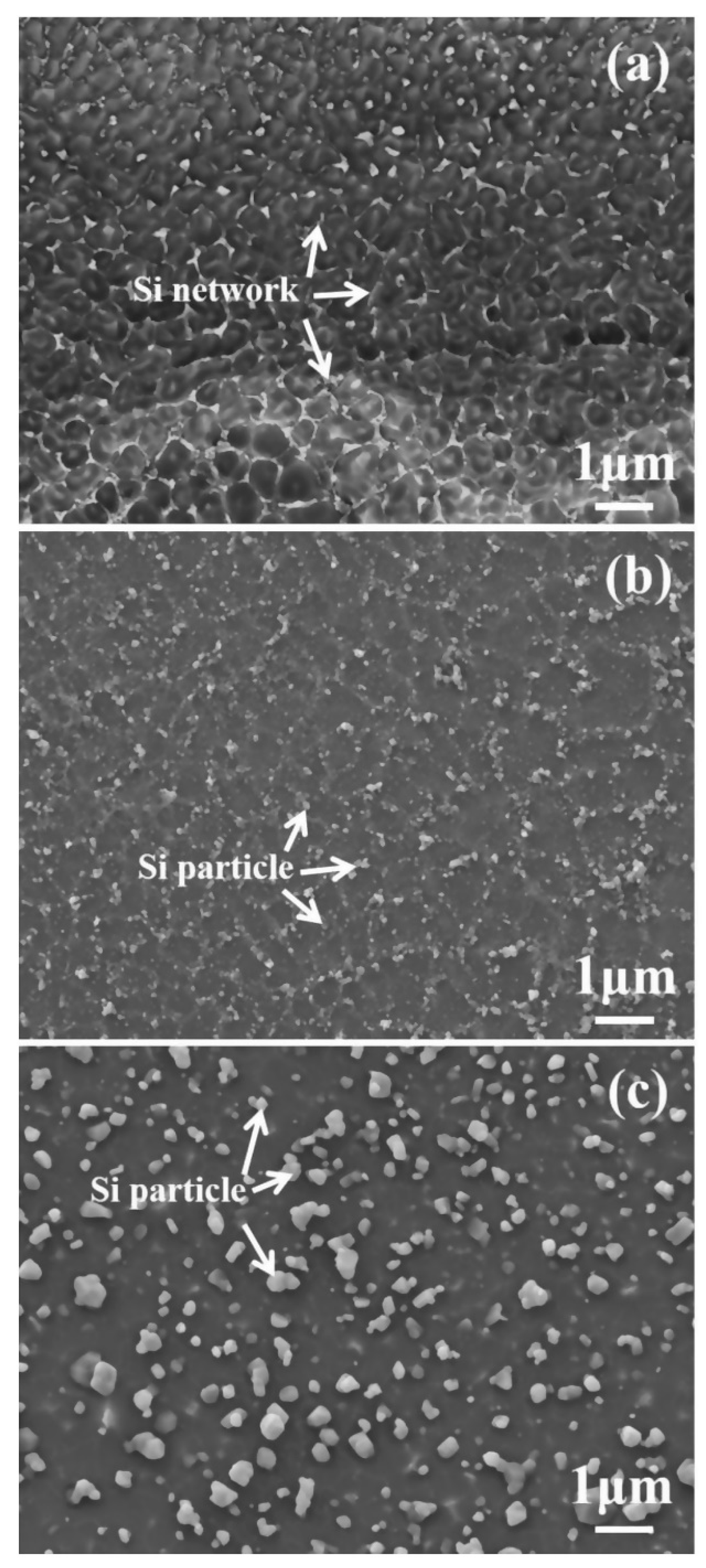
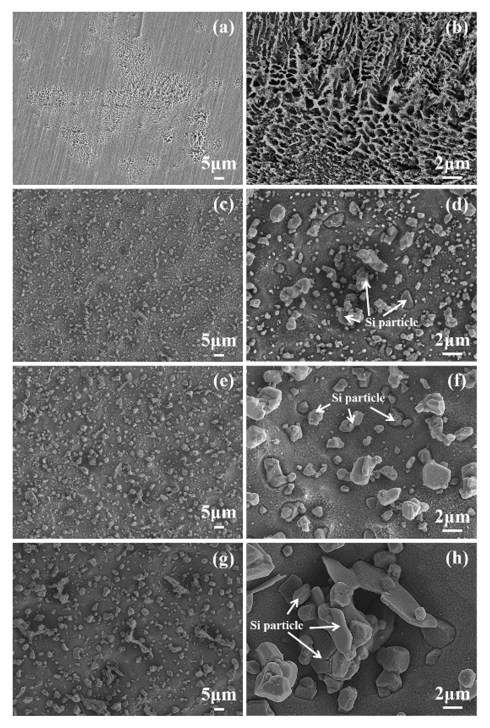
Post heat treatment parameters (temperature and time) affect the microstructure (grain size, Si distribution, etc.) of SLMed Al alloys, consequently affect the corrosion behaviors. Larger Al grains and broken Si shells results in the acceleration of the corrosion reaction, and the isolated Si particles hinder the compact oxide film formation on aluminum surfaces [63,65,66].
(5)
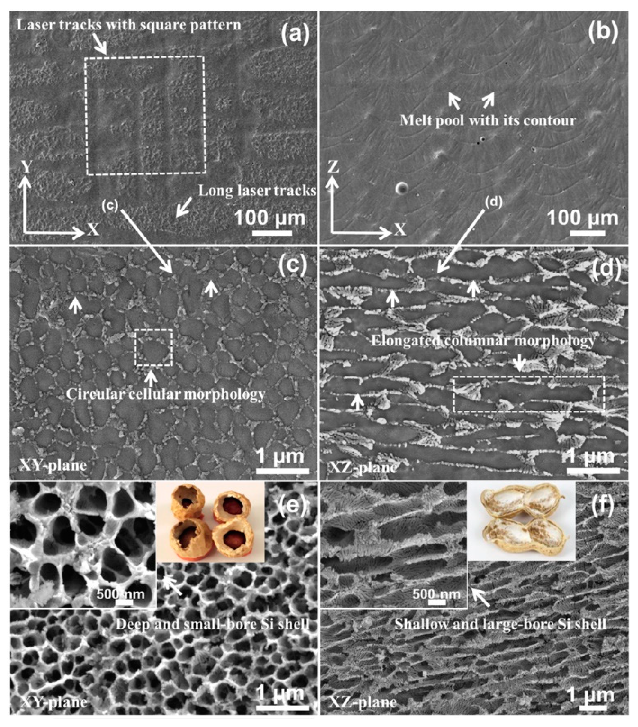
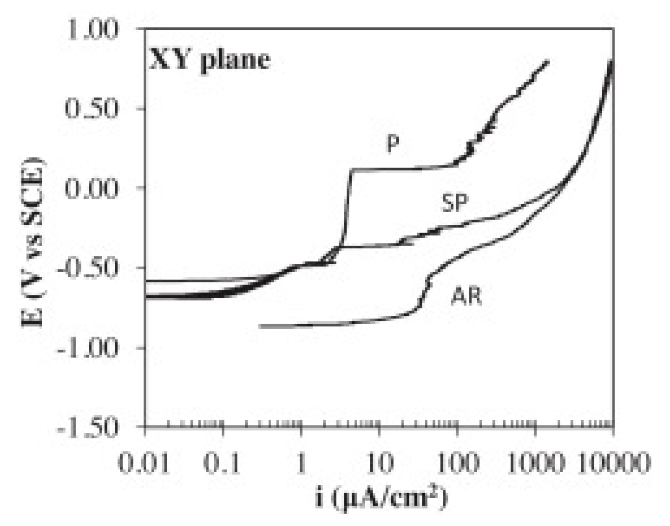
Due to the distinctly different microstructures in the two directions, the XZ-plane (parallel to the building direction) exhibits better corrosion resistance than the XY-plane [74]. Samples with as-printed surface show the worse corrosion resistance and the lower corrosion fatigue cycles, and this is owing to the rougher surface obtained from the direct print compared to the polished surface [64].
(6)
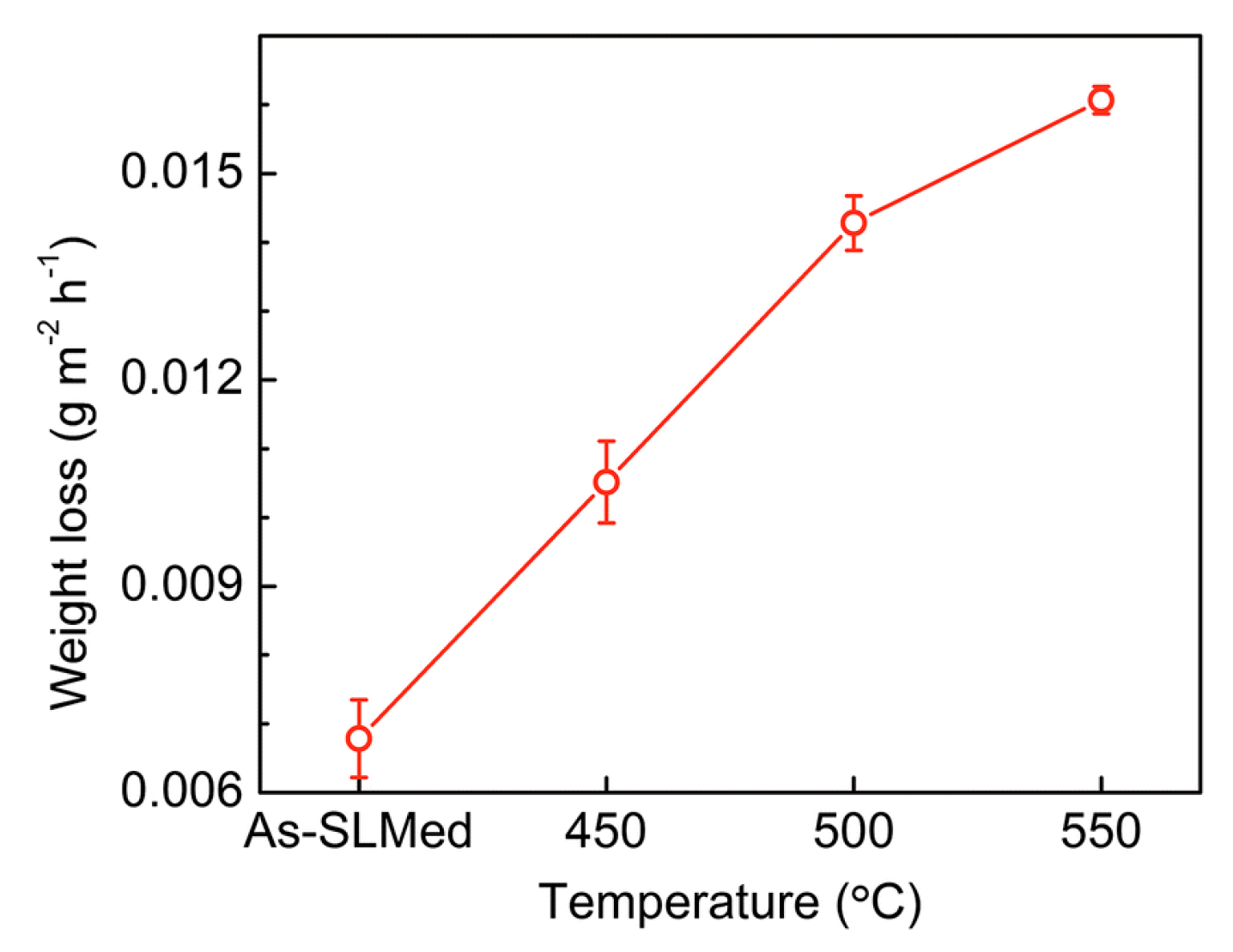
It is reported that proper post heat treatments could eliminate the residual stress existed in the SLM aluminum alloys, but the corrosion resistance decreases with increasing temperature of post heat treatment. Therefore, further studies on post heat treatments of SLMed Al alloys and other stress-relief techniques are needed to reduce the residual stress and meanwhile keep the corrosion resistance in a high level [67].
(7)
To further study the corrosion behaviors of SLMed alloy in corrosive atmosphere, it is inevitable to conduct the salt spray test in the future.
(8)
Other corrosion behavior aspects, which have been studied for conventional aluminum alloys, such as, intergranular corrosion and exfoliation corrosion, also need to be studied for SLMed aluminum alloys to gain more insights into the corrosion mechanism of SLMed Al alloys.
(9)
The corrosion behaviors of more types of Al alloys, including conventional Al alloys (1xxx-8xxx) and new Al alloys specially developed for SLM (for example, Scalmalloy), also need to be investigated for their potential future industrial applications.

Author Contributions

Writing—original draft preparation, H.C.; Writing—outline of the paper, review and editing, supervision, funding acquisition, C.Z., H.C. and C.Z. contribute equally to this paper; review and editing—D.J.; review and editing—D.W.; review and editing—W.L. All authors have read and agreed to the published version of the manuscript.

Funding

This work was supported by National Natural Science Foundation of China, grant number 51605287, and Natural Science Foundation of Shanghai, grant number 16ZR1417100. This work was also supported by the fund of State Key Laboratory of Long-life High Temperature Materials.

Acknowledgments

We appreciate Yanlong Ma (Professor in corrosion science at CQUT) for useful discussion.

Conflicts of Interest

The authors declare no conflict of interest.

References

  1. Zhang, L.; Zhang, S.S.; Zhu, H.H.; Wang, G.Q.; Zeng, X.Y. Investigation on the angular accuracy of selective laser melting. Int. J. Adv. Manuf. Techcol. 2019, 104, 3147–3153. [Google Scholar] [CrossRef]
  2. Rakesh, C.S.; Raja, A.; Nadig, P.; Jayaganthan, R.; Vasa, N.J. Influence of working environment and built orientation on the tensile properties of selective laser melted AlSi10Mg alloy. Mater. Sci. Eng. A 2019, 750, 141–151. [Google Scholar] [CrossRef]
  3. Mueller, M.; Riede, M.; Eberle, S.; Reutlinger, A.; Brandao, A.D.; Pambaguian, L.; Seidel, A.; Lopez, E.; Brueckner, F.; Beyer, E.; et al. Microstructural, mechanical, and thermo-physical characterization of hypereutectic AlSi40 fabricated by selective laser melting. J. Laser Appl. 2019, 31, 022321. [Google Scholar] [CrossRef]
  4. Li, Z.; Kuai, Z.; Bai, P.; Nie, Y.; Fu, G.; Liu, W.; Yang, S. Microstructure and Tensile Properties of AlSi10Mg Alloy Manufactured by Multi-Laser Beam Selective Laser Melting (SLM). Metals 2019, 9, 1337. [Google Scholar] [CrossRef] [Green Version]
  5. Zaharin, A.H.; Abdul Rani, M.A.; Azam, I.F.; Ginta, L.T.; Sallih, N.; Ahmad, A.; Yunus, A.N.; Zulkifli, Z.T. Effect of Unit Cell Type and Pore Size on Porosity and Mechanical Behavior of Additively Manufactured Ti6Al4V Scaffolds. Materials 2018, 11, 2402. [Google Scholar] [CrossRef] [Green Version]
  6. Wysocki, B.; Maj, P.; Sitek, R.; Buhagiar, J.; Kurzydłowski, J.K.; Święszkowski, W. Laser and Electron Beam Additive Manufacturing Methods of Fabricating Titanium Bone Implants. Appl. Sci. 2017, 7, 657. [Google Scholar] [CrossRef]
  7. Strakosova, A.; Kubásek, J.; Michalcová, A.; Průša, F.; Vojtěch, D.; Dvorský, D. High Strength X3NiCoMoTi 18-9-5 Maraging Steel Prepared by Selective Laser Melting from Atomized Powder. Materials 2019, 12, 4174. [Google Scholar] [CrossRef] [Green Version]
  8. Mugwagwa, L.; Yadroitsev, I.; Matope, S. Effect of Process Parameters on Residual Stresses, Distortions, and Porosity in Selective Laser Melting of Maraging Steel 300. Metals 2019, 9, 1042. [Google Scholar] [CrossRef] [Green Version]
  9. Narvan, M.; Al-Rubaie, S.K.; Elbestawi, M. Process-Structure-Property Relationships of AISI H13 Tool Steel Processed with Selective Laser Melting. Materials 2019, 12, 2284. [Google Scholar] [CrossRef] [Green Version]
  10. Tian, Z.; Zhang, C.; Wang, D.; Liu, W.; Fang, X.; Wellmann, D.; Zhao, Y.; Tian, Y. A Review on Laser Powder Bed Fusion of Inconel 625 Nickel-Based Alloy. Appl. Sci. 2019, 10, 81. [Google Scholar] [CrossRef] [Green Version]
  11. Calandri, M.; Yin, S.; Aldwell, B.; Calignano, F.; Lupoi, R.; Ugues, D. Texture and Microstructural Features at Different Length Scales in Inconel 718 Produced by Selective Laser Melting. Materials 2019, 12, 1293. [Google Scholar] [CrossRef] [PubMed] [Green Version]
  12. Dehghanghadikolaei, A.; Ibrahim, H.; Amerinatanzi, A.; Hashemi, M.; Moghaddam, N.S.; Elahinia, M. Improving corrosion resistance of additively manufactured nickel–titanium biomedical devices by micro-arc oxidation process. J. Mater. Sci. 2019, 54, 7333–7355. [Google Scholar] [CrossRef]
  13. Mehrpouya, M.; Dehghanghadikolaei, A.; Fotovvati, B.; Vosooghnia, A.; Emamian, S.S.; Gisario, A. The Potential of Additive Manufacturing in the Smart Factory Industrial 4.0: A Review. Appl. Sci. 2019, 9, 3865. [Google Scholar] [CrossRef] [Green Version]
  14. Manca, D.R.; Churyumov, A.Y.; Pozdniakov, A.V.; Prosviryakov, A.S.; Ryabov, D.K.; Krokhin, A.Y.; Korolev, V.A.; Daubarayte, D.K. Microstructure and Properties of Novel Heat Resistant Al-Ce-Cu Alloy for Additive Manufacturing. Met. Mater. Int. 2019, 25, 633–640. [Google Scholar] [CrossRef]
  15. Kimura, T.; Nakamoto, T.; Ozaki, T.; Sugita, K.; Mizuno, M.; Araki, H. Microstructural formation and characterization mechanisms of selective laser melted Al-Si-Mg alloys with increasing magnesium content. Mater. Sci. Eng. A 2019, 754, 786–798. [Google Scholar] [CrossRef]
  16. Karolus, M.; Maszybrocka, J.; Stwora, A.; Skrabalak, G. Residual stresses of alsi10mg fabricated by selective laser melting (SLM). Arch. Metall. Mater. 2019, 64, 1011–1016. [Google Scholar] [CrossRef]
  17. Rahmani, R.; Rosenberg, M.; Ivask, A.; Kollo, L. Comparison of Mechanical and Antibacterial Properties of TiO2/Ag Ceramics and Ti6Al4V-TiO2/Ag Composite Materials Using Combined SLM-SPS Techniques. Metals 2019, 9, 874. [Google Scholar] [CrossRef] [Green Version]
  18. DebRoy, T.; Wei, H.L.; Zuback, J.S.; Mukherjee, T.; Elmer, J.W.; Milewski, J.O.; Beese, A.M.; Wilson-Heid, A.; De, A.; Zhang, W. Additive manufacturing of metallic components—Process, structure and properties. Prog. Mater. Sci. 2018, 92, 112–224. [Google Scholar] [CrossRef]
  19. Hu, Z.H.; Zhang, H.; Zhu, H.H.; Xiao, Z.X.; Nie, X.J.; Zeng, X.Y. Microstructure, mechanical properties and strengthening mechanisms of AlCu5MnCdVA aluminum alloy fabricated by selective laser melting. Mater. Sci. Eng. A 2019, 759, 154–166. [Google Scholar] [CrossRef]
  20. Gu, H.Y.; Li, S.; Pavier, M.; Attallah, M.M.; Paraskevoulakos, C.; Shterenlikht, A. Fracture of three-dimensional lattices manufactured by selective laser melting. Int. J. Solids Struct. 2019, 180, 147–159. [Google Scholar] [CrossRef]
  21. Delahaye, J.; Tchuindjang, J.T.; Lecomte-Beckers, J.; Rigo, O.; Habraken, A.M.; Mertens, A. Influence of Si precipitates on fracture mechanisms of AlSi10Mg parts processed by Selective Laser Melting. Acta Mater. 2019, 175, 160–170. [Google Scholar] [CrossRef]
  22. Zhou, Y.; Duan, L.C.; Wen, S.F.; Wei, Q.S.; Shi, Y.S. Enhanced micro-hardness and wear resistance of Al-15Si/TiC fabricated by selective laser melting. Compos. Commun. 2018, 10, 64–67. [Google Scholar] [CrossRef]
  23. Zhao, J.W.; Easton, M.; Qian, M.; Leary, M.; Brandt, M. Effect of building direction on porosity and fatigue life of selective laser melted AlSi12Mg alloy. Mater. Sci. Eng. A 2018, 729, 76–85. [Google Scholar] [CrossRef]
  24. Zhang, H.; Gu, D.D.; Yang, J.K.; Dai, D.H.; Zhao, T.; Hong, C.; Gasser, A.; Poprawe, R. Selective laser melting of rare earth element Sc modified aluminum alloy: Thermodynamics of precipitation behavior and its influence on mechanical properties. Addit. Manuf. 2018, 23, 1–12. [Google Scholar] [CrossRef]
  25. Wang, Y.C.; Shi, J.; Lu, S.Q.; Xiao, W.H. Investigation of Porosity and Mechanical Properties of Graphene Nanoplatelets-Reinforced AlSi10 Mg by Selective Laser Melting. J. Micro Nano-Manuf. 2018, 6, 010902. [Google Scholar] [CrossRef] [Green Version]
  26. Uzan, N.E.; Shneck, R.; Yeheskel, O.; Frage, N. High-temperature mechanical properties of AlSi10Mg specimens fabricated by additive manufacturing using selective laser melting technologies (AM-SLM). Addit. Manuf. 2018, 24, 257–263. [Google Scholar] [CrossRef]
  27. Takata, N.; Kodaira, H.; Suzuki, A.; Kobashi, M. Size dependence of microstructure of AlSi10Mg alloy fabricated by selective laser melting. Mater. Charact. 2018, 143, 18–26. [Google Scholar] [CrossRef]
  28. Liu, Y.; Yang, Y.; Mai, S.; Wang, D.; Song, C. Investigation into spatter behavior during selective laser melting of AISI 316L stainless steel powder. Mater. Des. 2015, 87, 797–806. [Google Scholar] [CrossRef]
  29. Spierings, A.B.; Dawson, K.; Dumitraschkewitz, P.; Pogatscher, S.; Wegener, K. Microstructure characterization of SLM-processed Al-Mg-Sc-Zr alloy in the heat treated and HIPed condition. Addit. Manuf. 2018, 20, 173–181. [Google Scholar] [CrossRef]
  30. Liu, M.L.; Takata, N.; Suzuki, A.; Kobashi, M. Microstructural characterization of cellular AlSi10Mg alloy fabricated by selective laser melting. Mater. Des. 2018, 157, 478–491. [Google Scholar] [CrossRef]
  31. Liu, J.; Gu, D.D.; Chen, H.Y.; Dai, D.H.; Zhang, H. Influence of substrate surface morphology on wetting behavior of tracks during selective laser melting of aluminum-based alloys. J. Zhejiang Univ. Sci. A 2018, 19, 111–121. [Google Scholar] [CrossRef]
  32. Fousova, M.; Dvorsky, D.; Vronka, M.; Vojtech, D.; Lejcek, P. The Use of Selective Laser Melting to Increase the Performance of AlSi9Cu3Fe Alloy. Materials 2018, 11, 1918. [Google Scholar] [CrossRef] [PubMed] [Green Version]
  33. Zou, J.; Zhu, Y.; Pan, M.; Xie, T.; Chen, X.; Yang, H. A study on cavitation erosion behavior of AlSi10Mg fabricated by selective laser melting (SLM). Wear 2017, 376, 496–506. [Google Scholar] [CrossRef] [Green Version]
  34. Zhang, W.Q.; Zhu, H.H.; Hu, Z.H.; Zeng, X.Y. Study on the Selective Laser Melting of AlSi10Mg. Acta Metall. Sin. 2017, 53, 918–926. [Google Scholar] [CrossRef]
  35. Yang, T.; Liu, T.T.; Liao, W.H.; MacDonald, E.; Wei, H.L.; Chen, X.Y.; Jiang, L.Y. The influence of process parameters on vertical surface roughness of the AlSi10Mg parts fabricated by selective laser melting. J. Mater. Process. Technol. 2019, 266, 26–36. [Google Scholar] [CrossRef]
  36. Majeed, A.; Lv, J.X.; Zhang, Y.F.; Muzamil, M.; Waqas, A.; Shamim, K.; Qureshi, M.E.; Zafar, F. An investigation into the influence of processing parameters on the surface quality of AlSi10Mg parts by SLM process. In Proceedings of the 2019 16th International Bhurban Conference on Applied Sciences and Technology (IBCAST), Islamabad, Pakistan, 8–12 January 2019; pp. 143–147. [Google Scholar]
  37. Maamoun, A.H.; Xue, Y.F.; Elbestawi, M.A.; Veldhuis, S.C. The Effect of Selective Laser Melting Process Parameters on the Microstructure and Mechanical Properties of A16061 and AlSi10Mg Alloys. Materials 2019, 12, 12. [Google Scholar] [CrossRef] [Green Version]
  38. Montero-Sistiaga, M.L.; Mertens, R.; Vrancken, B.; Wang, X.; Van Hooreweder, B.; Kruth, J.-P.; Van Humbeeck, J. Changing the alloy composition of Al7075 for better processability by selective laser melting. J. Mater. Process. Technol. 2016, 238, 437–445. [Google Scholar] [CrossRef]
  39. Kairy, S.K.; Gharbi, O.; Nicklaus, J.; Jiang, D.; Hutchinson, C.R.; Birbilis, N. On the Characterization of a Hitherto Unreported Icosahedral Quasicrystal Phase in Additively Manufactured Aluminum Alloy AA7075. Metall. Mater. Trans. A 2018, 50, 529–533. [Google Scholar] [CrossRef] [Green Version]
  40. Bagherifard, S.; Beretta, N.; Monti, S.; Riccio, M.; Bandini, M.; Guagliano, M. On the fatigue strength enhancement of additive manufactured AlSi10Mg parts by mechanical and thermal post-processing. Mater. Des. 2018, 145, 28–41. [Google Scholar] [CrossRef]
  41. Strößner, J.; Terock, M.; Glatzel, U. Mechanical and Microstructural Investigation of Nickel-Based Superalloy IN718 Manufactured by Selective Laser Melting (SLM). Adv. Eng. Mater. 2015, 17, 1099–1105. [Google Scholar] [CrossRef]
  42. Wang, L.F.; Sun, J.; Zhu, X.G.; Cheng, L.Y.; Shi, Y.; Guo, L.; Yan, B. Effects of T2 Heat Treatment on Microstructure and Properties of the Selective Laser Melted Aluminum Alloy Samples. Materials 2018, 11, 66. [Google Scholar] [CrossRef] [PubMed] [Green Version]
  43. Takata, N.; Kodaira, H.; Sekizawa, K.; Suzuki, A.; Kobashi, M. Change in microstructure of selectively laser melted AlSi10Mg alloy with heat treatments. Mater. Sci. Eng. A 2017, 704, 218–228. [Google Scholar] [CrossRef]
  44. Casati, R.; Lemke, J.; Alarcon, A.; Vedani, M. Aging Behavior of High-Strength Al Alloy 2618 Produced by Selective Laser Melting. Metall. Mater. Trans. A 2017, 48, 575–579. [Google Scholar] [CrossRef]
  45. Tradowsky, U.; White, J.; Ward, R.M.; Read, N.; Reimers, W.; Attallah, M.M. Selective laser melting of AlSi10Mg: Influence of post-processing on the microstructural and tensile properties development. Mater. Des. 2016, 105, 212–222. [Google Scholar] [CrossRef] [Green Version]
  46. Chen, B.; Moon, S.K.; Yao, X.; Bi, G.; Shen, J.; Umeda, J.; Kondoh, K. Strength and strain hardening of a selective laser melted AlSi10Mg alloy. Scr. Mater. 2017, 141, 45–49. [Google Scholar] [CrossRef]
  47. Aversa, A.; Lorusso, M.; Cattano, G.; Manfredi, D.; Calignano, F.; Ambrosio, E.P.; Biamino, S.; Fino, P.; Lombardi, M.; Pavese, M. A study of the microstructure and the mechanical properties of an Al-Si-Ni alloy produced via selective laser melting. J. Alloys Compd. 2017, 695, 1470–1478. [Google Scholar] [CrossRef]
  48. Ma, P.; Jia, Y.D.; Prashanth, K.G.; Scudino, S.; Yu, Z.S.; Eckert, J. Microstructure and phase formation in Al-20Si-5Fe-3Cu-1Mg synthesized by selective laser melting. J. Alloys Compd. 2016, 657, 430–435. [Google Scholar] [CrossRef]
  49. Aboulkhair, N.T.; Everitt, N.M.; Maskery, I.; Ashcroft, I.; Tuck, C. Selective laser melting of aluminum alloys. MRS Bull. 2017, 42, 311–319. [Google Scholar] [CrossRef]
  50. Kimura, T.; Nakamoto, T. Microstructures and mechanical properties of A356 (AlSi7Mg0.3) aluminum alloy fabricated by selective laser melting. Mater. Des. 2016, 89, 1294–1301. [Google Scholar] [CrossRef]
  51. Biffi, C.A.; Fiocchi, J.; Tuissi, A. Selective laser melting of AlSi10 Mg: Influence of process parameters on Mg2Si precipitation and Si spheroidization. J. Alloys Compd. 2018, 755, 100–107. [Google Scholar] [CrossRef]
  52. Fiocchi, J.; Tuissi, A.; Bassani, P.; Biffi, C.A. Low temperature annealing dedicated to AlSi10Mg selective laser melting products. J. Alloys Compd. 2017, 695, 3402–3409. [Google Scholar] [CrossRef]
  53. Roberts, C.E.; Bourell, D.; Watt, T.; Cohen, J. A novel processing approach for additive manufacturing of commercial aluminum alloys. Phys. Procedia 2016, 83, 909–917. [Google Scholar] [CrossRef] [Green Version]
  54. Wang, L.F.; Sun, J.; Yu, X.L.; Shi, Y.; Zhu, X.G.; Cheng, L.Y.; Liang, H.H.; Yan, B.; Guo, L.J. Enhancement in mechanical properties of selectively laser-melted AlSi10Mg aluminum alloys by T6-like heat treatment. Mater. Sci. Eng. A 2018, 734, 299–310. [Google Scholar] [CrossRef]
  55. Fousova, M.; Dvorsky, D.; Michalcova, A.; Vojtech, D. Changes in the microstructure and mechanical properties of additively manufactured AlSi10Mg alloy after exposure to elevated temperatures. Mater. Charact. 2018, 137, 119–126. [Google Scholar] [CrossRef]
  56. Chen, T.; Wang, L.Z.; Tan, S. Effects of vacuum annealing treatment on microstructures and residual stress of AlSi10Mg parts produced by selective laser melting process. Mod. Phys. Lett. B 2016, 30, 1650255. [Google Scholar] [CrossRef]
  57. Prashanth, K.G.; Scudino, S.; Klauss, H.J.; Surreddi, K.B.; Lober, L.; Wang, Z.; Chaubey, A.K.; Kuhn, U.; Eckert, J. Microstructure and mechanical properties of Al-12Si produced by selective laser melting: Effect of heat treatment. Mater. Sci. Eng. A 2014, 590, 153–160. [Google Scholar] [CrossRef]
  58. Wang, X.J.; Zhang, L.C.; Fang, M.H.; Sercombe, T.B. The effect of atmosphere on the structure and properties of a selective laser melted Al-12Si alloy. Mater. Sci. Eng. A 2014, 597, 370–375. [Google Scholar] [CrossRef] [Green Version]
  59. Shuai, C.J.; He, C.X.; Xu, L.; Li, Q.; Chen, T.; Yang, Y.W.; Peng, S.P. Wrapping effect of secondary phases on the grains: Increased corrosion resistance of Mg-Al alloys. Virtual Phys. Prototyp. 2018, 13, 292–300. [Google Scholar] [CrossRef]
  60. Cabrini, M.; Lorenzi, S.; Pastore, T.; Pellegrini, S.; Testa, C.; Manfredi, D.; Ambrosio, E.P.; Calignano, F.; Lorusso, M.; Fino, P. Analisys of corrosion resistance of the aismomg alloy obtained by additive manufacturing in chloride solution. Metall. Ital. 2016, 108, 137–146. [Google Scholar]
  61. Cottam, R.; Brandt, M. Laser Surface Treatment to Improve the Surface Corrosion Properties of Nickel-Aluminum Bronze. In Laser Surface Engineering; Woodhead Publishing: Cambridge, UK, 2015; pp. 469–481. [Google Scholar] [CrossRef]
  62. Fefelov, A.S.; Merkushev, A.G.; Chikova, O.A.; Finkel’shtein, A.B. Microstructure and Mechanical Properties of Objects Prepared by Selective Laser Melting of AKD12 Powder. Metallurgist 2018, 62, 470–475. [Google Scholar] [CrossRef]
  63. Rafieazad, M.; Mohammadi, M.; Nasiri, A.M. On microstructure and early stage corrosion performance of heat treated direct metal laser sintered AlSi10Mg. Addit. Manuf. 2019, 28, 107–119. [Google Scholar] [CrossRef]
  64. Yang, Y.; Chen, Y.; Zhang, J.X.; Gu, X.H.; Qin, P.; Dai, N.W.; Li, X.P.; Kruth, J.P.; Zhang, L.C. Improved corrosion behavior of ultrafine-grained eutectic Al-12Si alloy produced by selective laser melting. Mater. Des. 2018, 146, 239–248. [Google Scholar] [CrossRef]
  65. Gu, X.; Zhang, J.; Fan, X.; Dai, N.; Xiao, Y.; Zhang, L.-C. Abnormal corrosion behavior of selective laser melted AlSi10Mg alloy induced by heat treatment at 300 °C. J. Alloys Compd. 2019, 803, 314–324. [Google Scholar] [CrossRef]
  66. Rubben, T.; Revilla, R.I.; De Graeve, I. Influence of heat treatments on the corrosion mechanism of additive manufactured AlSi10Mg. Corros. Sci. 2019, 147, 406–415. [Google Scholar] [CrossRef]
  67. Gu, X.-H.; Zhang, J.-X.; Fan, X.-L.; Zhang, L.-C. Corrosion Behavior of Selective Laser Melted AlSi10Mg Alloy in NaCl Solution and Its Dependence on Heat Treatment. Acta Metall. Sin. (Engl. Lett.) 2019. [Google Scholar] [CrossRef] [Green Version]
  68. Chen, Y.; Zhang, J.; Gu, X.; Dai, N.; Qin, P.; Zhang, L.-C. Distinction of corrosion resistance of selective laser melted Al-12Si alloy on different planes. J. Alloys Compd. 2018, 747, 648–658. [Google Scholar] [CrossRef]
  69. Bian, P.Y.; Shao, X.D.; Du, J.L. Wear and Corrosion Resistance of AlSi10Mg by Selective Laser Melting and Micro-arc Oxidation. China Surf. Eng. 2018, 31, 88–95. [Google Scholar] [CrossRef]
  70. Spierings, A.B.; Dawson, K.; Kern, K.; Palm, F.; Wegener, K. SLM-processed Sc- and Zr- modified Al-Mg alloy: Mechanical properties and microstructural effects of heat treatment. Mater. Sci. Eng. A 2017, 701, 264–273. [Google Scholar] [CrossRef]
  71. Zhang, J.; Song, B.; Wei, Q.; Bourell, D.; Shi, Y. A review of selective laser melting of aluminum alloys: Processing, microstructure, property and developing trends. J. Mater. Sci. Technol. 2019, 35, 270–284. [Google Scholar] [CrossRef]
  72. Sander, G.; Tan, J.; Balan, P.; Gharbi, O.; Feenstra, D.R.; Singer, L.; Thomas, S.; Kelly, R.G.; Scully, J.R.; Birbilis, N. Corrosion of Additively Manufactured Alloys: A Review. Corrosion 2018, 74, 1318–1350. [Google Scholar] [CrossRef] [Green Version]
  73. Kong, D.; Dong, C.; Ni, X.; Li, X. Corrosion of metallic materials fabricated by selective laser melting. npj Mater. Degrad. 2019, 3, 24. [Google Scholar] [CrossRef]
  74. Aboulkhair, N.T.; Maskery, I.; Tuck, C.; Ashcroft, I.; Everitt, N.M. The microstructure and mechanical properties of selectively laser melted AlSi10Mg: The effect of a conventional T6-like heat treatment. Mater. Sci. Eng. A 2016, 667, 139–146. [Google Scholar] [CrossRef]
  75. Manfredi, D.; Calignano, F.; Krishnan, M.; Canali, R.; Ambrosio, E.P.; Atzeni, E. From Powders to Dense Metal Parts: Characterization of a Commercial AlSiMg Alloy Processed through Direct Metal Laser Sintering. Materials 2013, 6, 856–869. [Google Scholar] [CrossRef] [PubMed] [Green Version]
  76. Rao, H.; Giet, S.; Yang, K.; Wu, X.; Davies, C.H.J. The influence of processing parameters on aluminium alloy A357 manufactured by Selective Laser Melting. Mater. Des. 2016, 109, 334–346. [Google Scholar] [CrossRef]
  77. Liu, Y.; Yang, Y.; Wang, D. A study on the residual stress during selective laser melting (SLM) of metallic powder. Int. J. Adv. Manuf. Technol. 2016, 87, 647–656. [Google Scholar] [CrossRef]
  78. Ponnusamy, P.; Masood, S.H.; Ruan, D.; Palanisamy, S.; Rashid, R. High strain rate dynamic behaviour of AlSi12 alloy processed by selective laser melting. Int. J. Adv. Manuf. Technol. 2018, 97, 1023–1035. [Google Scholar] [CrossRef]
  79. Uzan, N.; Rosenthal, I.; Stern, A. Macro- and Microstructural Characterization of Cup-Shaped AlSi10Mg Components Fabricated by Selective Laser Melting (SLM). Metallogr. Microstruct. Anal. 2016, 5, 512–519. [Google Scholar] [CrossRef]
  80. Gharbi, O.; Jiang, D.; Feenstra, D.R.; Kairy, S.K.; Wu, Y.; Hutchinson, C.R.; Birbilis, N. On the corrosion of additively manufactured aluminium alloy AA2024 prepared by selective laser melting. Corros. Sci. 2018, 143, 93–106. [Google Scholar] [CrossRef]
  81. Prashanth, K.G.; Debalina, B.; Wang, Z.; Gostin, P.F.; Gebert, A.; Calin, M.; Kuhn, U.; Kamaraj, M.; Scudino, S.; Eckert, J. Tribological and corrosion properties of Al-12Si produced by selective laser melting. J. Mater. Res. 2014, 29, 2044–2054. [Google Scholar] [CrossRef]
  82. Ma, P.; Prashanth, K.G.; Scudino, S.; Jia, Y.D.; Wang, H.W.; Zou, C.M.; Wei, Z.J.; Eckert, J. Influence of Annealing on Mechanical Properties of Al-20Si Processed by Selective Laser Melting. Metals 2014, 4, 28–36. [Google Scholar] [CrossRef]
  83. Zakay, A.; Aghion, E. Effect of Post-heat Treatment on the Corrosion Behavior of AlSi10Mg Alloy Produced by Additive Manufacturing. JOM 2019, 71, 1150–1157. [Google Scholar] [CrossRef]
  84. Zhang, H.; Zhu, H.H.; Nie, X.J.; Qi, T.; Hu, Z.H.; Zeng, X.Y. Fabrication and Heat Treatment of High Strength Al-Cu-Mg alloy Processed Using Selective Laser Melting. Laser 3D Manufacturing III; International Society for Optics and Photonics: San Francisco, CA, USA, 2016. [Google Scholar] [CrossRef]
  85. Cabrini, M.; Lorenzi, S.; Pastore, T.; Pellegrini, S.; Ambrosio, E.P.; Calignano, F.; Manfredi, D.; Pavese, M.; Fino, P. Effect of heat treatment on corrosion resistance of DMLS AlSi10Mg alloy. Electrochim. Acta 2016, 206, 346–355. [Google Scholar] [CrossRef]
  86. Leon, A.; Aghion, E. Effect of surface roughness on corrosion fatigue performance of AlSi10Mg alloy produced by Selective Laser Melting (SLM). Mater. Charact. 2017, 131, 188–194. [Google Scholar] [CrossRef]
  87. Leon, A.; Shirizly, A.; Aghion, E. Corrosion Behavior of AlSi10Mg Alloy Produced by Additive Manufacturing (AM) vs. Its Counterpart Gravity Cast Alloy. Metals 2016, 6, 148. [Google Scholar] [CrossRef]
  88. Cabrini, M.; Lorenzi, S.; Pastore, T.; Pellegrini, S.; Pavese, M.; Fino, P.; Ambrosio, E.P.; Calignano, F.; Manfredi, D. Corrosion resistance of direct metal laser sintering AlSiMg alloy. Surf. Interface Anal. 2016, 48, 818–826. [Google Scholar] [CrossRef]
  89. Revilla, R.I.; De Graeve, I. Influence of Si Content on the Microstructure and Corrosion Behavior of Additive Manufactured Al-Si Alloys. J. Electrochem. Soc. 2018, 165, C926–C932. [Google Scholar] [CrossRef]
  90. Fathi, P.; Mohammadi, M.; Duan, X.; Nasiri, A.M. A comparative study on corrosion and microstructure of direct metal laser sintered AlSi10Mg_200C and die cast A360.1 aluminum. J. Mater. Process. Technol. 2018, 259, 1–14. [Google Scholar] [CrossRef]
  91. Cabrini, M.; Lorenzi, S.; Pastore, T.; Pellegrini, S.; Manfredi, D.; Fino, P.; Biamino, S.; Badini, C. Evaluation of corrosion resistance of Al–10Si–Mg alloy obtained by means of Direct Metal Laser Sintering. J. Mater. Process. Technol. 2016, 231, 326–335. [Google Scholar] [CrossRef]
Figure 1. The schematic diagram of SLM [28].
Metals 10 00102 g001
Figure 2. The microstructure of two different planes of SLM Al-12Si alloy: (a) polished XY plane; (b) polished XZ plane; (c) eutectic Si networks of XY plane; (d) eutectic Si networks of XZ plane; (e) the eutectic Si shells of XY plane; (f) the eutectic Si shells of XZ plane [68].
Metals 10 00102 g002
Figure 3. SEM of the SLM AlSi10Mg: (a) the untreated; (b) heat treated at 300 °C for 2 h; (c) heat treated at 400°C for 2 h [65].
Metals 10 00102 g003
Figure 4. Weight loss rate of the SLM produced Al-12Si and casted Al-12Si after immersion in the aerated 3.5 wt. % NaCl solution [64].
Metals 10 00102 g004
Figure 5. Corrosion morphologies of Al-12Si after 14 days immersion in 3.5 wt. % NaCl solution: (a,b) as-casted Al-12Si alloy; (c,d) SLM produced Al-12Si alloy [64].
Metals 10 00102 g005
Figure 6. The polarization curves of printed, ground and casted aluminum alloy produced by DMLS [90].
Metals 10 00102 g006
Figure 7. Polarization curves of printed AlSi10Mg alloy in diluted Harrison’s solution on XY specimens with different surface treatment [91].
Metals 10 00102 g007
Figure 8. Polarization curves of printed AlSi10Mg alloy in diluted Harrison’s solution on XY specimens with different surface treatment [91].
Metals 10 00102 g008
Figure 9. The EIS plots of SLM and casted Al-12Si aluminum alloy: (a) Nyquist plots; (b,c) Bode plots; (d) fitting equivalent circuit diagram [65].
Metals 10 00102 g009
Figure 10. Weight loss of untreated and additionally heat-treated SLM AlSi10Mg alloy [67].
Metals 10 00102 g010
Figure 11. SEM micrographs of SLM produced AlSi10Mg alloys after 45 days immersion in 3.5 wt. % NaCl solution: (a,b) untreated; (c,d) post heat treatment at 450 °C; (e,f) post heat treatment at 500 °C; (g,h) post heat treatment at 550 °C [67].
Metals 10 00102 g011
Figure 12. EIS spectra of the samples tested in Harrison solution: (a) Nyquist plot; (b) the fitting equivalent circuit [83].
Metals 10 00102 g012
Table 1. Summary of the reported study on corrosion behaviors of SLM prepared aluminum alloys.
AlloysElectrolyte SolutionCorrosion MeasurementInfluence FactorsReference
AlSi10Mg3.5 wt. % NaClPolarization curve, EIS, corrosion morphology, weight lossTemperature of post heat treatment[65]
AlSi10Mg3.5 wt. % NaClOCP, Polarization curve, EIS, corrosion morphologyTemperature of post heat treatment[63]
AlSi10MgHarrison’s solutionOCP, Polarization curve, EIS, corrosion morphologyTemperature of post heat treatment, surface roughness[85]
AlSi10Mg0.1 M NaCl solutionOCP, Polarization curve, corrosion morphology, SKPFMTemperature of post heat treatment[66]
AlSi10Mg3.5 wt. % NaClPolarization curve, EIS, corrosion morphology, weight lossTemperature of post heat treatment[67]
AlSi10Mg3.5 wt. % NaClPolarization curve, EIS, corrosion morphology, weight loss, low cycle fatigueSurface roughness[86]
AlSi10Mg3.5 wt. % NaClPolarization curve, weight loss, corrosion morphology, low cycle corrosion fatigueSLM and cast[87]
AlSi10MgHarrison’s solutionPolarization curve, corrosion morphologyDifferent surface treatment[88]
Al-12Si0.01 M, 0.1 M, 1 M HNO3 solutionweight loss, corrosion morphologyTemperature of post heat treatment[81]
Al-12Si3.5 wt. % NaClPolarization curve, EIS, corrosion morphology, weight lossSLM and cast[64]
Al-12Si3.5 wt. % NaClOCP, Polarization curve, EIS, corrosion morphologyPrinting plane[68]
AA20240.01 M, 0.1 M, 0.6 M NaClPolarization curve, elemental dissolution profilesSLM and cast[80]
OCP: open circuit potential; EIS: electrochemical impedance spectrum.

