1. Introduction
Mosquito-transmitted diseases are a major, global human health problem [
1]. Pathogens transmitted by mosquito bites cause illnesses that kill an estimated 700,000 people each year [
2]. Personal protection from mosquito-borne diseases has largely involved the use of chemical repellents applied to clothing and skin or insecticides either sprayed on garments before use or bound to textiles or garments to survive multiple uses and washes. Insecticide-treated textiles in the form of long-lasting insecticidal bed nets (LLINs) are also used for mosquito control in malaria-endemic areas. According to the World Health Organization, pyrethroid-treated bed nets have played a vital role in reducing malaria in Africa (World Health Organization (2019), World Malaria Report, WHO, Geneva, Switzerland [
3]). Between 2000 and 2015, an estimated 663 million clinical cases of malaria were averted, of which 68% were attributed to the wide-area deployment of LLINs [
4]. The use of insecticide-treated curtains [
5,
6], long-lasting insecticidal bed nets, and insecticide-treated clothing [
7] have substantially reduced the transmission of vector-borne pathogens. Unfortunately, the widespread use of insecticides has also led to the development of insecticide-resistant mosquitoes, and the insecticides are now ineffective in many places [
8].
Furthermore, in spite of the benefits from insecticide-treated textiles, there are potential deleterious health effects [
7]. Since the garments are in continuous contact with the skin, the potential for insecticide exposure is increased. Permethrin is the principal insecticide used to treat clothing [
9]. Development of safe, alternative insecticides for textiles is costly and requires regulatory approvals for new chemistry. Because of the potential health risks from the use of pesticides, people today given a choice prefer to avoid insecticide exposure. Development of mosquito-bite-resistant garments without insecticides that are comfortable and as effective (or more effective) than insecticide-treated garments would be a “game changer” and provide to the public, for the first time, a choice. We have achieved this objective.
Fabrics inherently are favorable structures for producing physical barriers against insects. Textiles have a three-dimensional structure assembled with interlacements or intermeshing fibers and yarns in organized patterns [
10]. The design of fibers and yarns produce textile structures with a diverse range of properties, some of which could provide insect protection [
11]. Fabrics have been specifically designed as physical barriers against environmental factors such as water [
12], airflow [
13], or heat and cold [
14]. The existence of open spaces between fibers and yarns ensures fabric breathability and thermal comfort [
15]; however, these spaces produce pores through a fabric allowing penetration of human olfactory (smell) and thermal (temperature) cues that attract mosquitoes [
16]. The fabric pores serve as channels for the mosquito to take a blood meal. The objective of our research is to develop a mathematical model to predict blood feeding across textiles that could be used to develop a practical, non-insecticidal, bite-resistant garment.
2. Materials and Methods
2.1. Mosquitoes
Adult, female yellow fever mosquitoes,
Aedes aegypti (Diptera: Culicidae), are a major vector of pathogens that cause animal and human diseases worldwide [
17,
18,
19] and were used as a model insect for the studies that follow.
Ae. aegypti females (
Figure 1A and
Figure S1) were obtained from a colony maintained in the Dearstyne Entomology Laboratory at North Carolina State University, Raleigh, NC, USA. The mosquito colony has been continuously reared for approximately 5 years and is free of pathogens. Adults were kept at 27 °C and 80% relative humidity with a 14:10 h light: dark photoperiod. Adults were provisioned with a 10% sucrose solution (in distilled water)
ad libitum. To obtain eggs for colony maintenance, female mosquitoes were fed porcine blood (obtained from a local abattoir) using an
in vitro blood-feeding device (described later). Larvae were kept under the same environmental conditions as adults and fed a porcine liver powder: brewer’s yeast mixture (2:1, wt:wt). Larval rearing water was dechlorinated using a standard aquarium dechlorinating agent.
2.2. In Vitro Feeding/Bioassay System
An
in vitro bioassay system was developed (shown in
Figure S2A) to blood feed mosquitoes for routine colony maintenance and to bioassay the barrier materials for bite resistance. The major components of the system are a blood-feeding reservoir, Plexiglas
® cage, and a circulating water bath for regulating the temperature of the blood. The blood-feeding reservoir is designed to contain the blood, fix a feeding membrane over the blood, and fix barrier materials on top of the feeding membrane for bioassays [
20]. Briefly, the blood reservoir (16.5 cm length × 3.5 cm width × 0.5 cm depth) was produced with a hand-held router from a rectangular block of Plexiglas
® (28 cm length × 5.5 cm width × l cm thickness). A hole (4 mm diameter) was drilled at the center of the top and bottom edge through the plastic into the blood reservoir. A tap was used to cut threads into the plastic so that a valve could be screwed into the top and bottom holes. Two holes (each 4 mm diameter) were drilled from the bottom edge of the device through the plastic to the blood reservoir. A loop of stainless-steel tubing (3 mm diameter) was placed into the blood reservoir, and the tubing was inserted through the holes so that the cut ends protruded out of the plastic. Epoxy cement was used to seal the tubing in place inside the blood reservoir of the device. The ends of the tubing were connected to a circulating water bath to heat the blood.
For blood feeding, a transparent collagen film (product code 894010.95; Devro, Inc., Columbia, SC, USA) was hydrated in distilled water and stretched over the top of the device. A gasket, cut from a sheet of cork-rubber composite (Fel-Pro, part no. 3019; AutoZone, Raleigh, NC, USA) was placed on top of the collagen film. A rectangular piece of plastic (3 mm thick) the size of the blood-feeding device was then placed on top of the gasket. The central area of both the rubber gasket and plastic frame was removed so that the collagen film is fully exposed to the mosquitoes. Metal binder clips hold the gasket and frame in place on top of the blood-feeding device, preventing leakage of blood. A 30 mL syringe filled with blood was then attached to the valve that was screwed into the top hole of the blood-feeding device. With the device tilted at a slight downward angle, the blood was slowly transferred into the reservoir. The valve attached to the bottom of the device was opened to allow air displacement as the blood is added. When the device was filled with blood, both valves were closed, and the circulating water bath was started to warm the blood to 35 °C.
The barrier materials (for example, the plastic blocks shown in
Figure S2C; the barrier materials tested are in toto listed in
Table 1) to be evaluated for bite resistance were cut exactly to fit over the collagen film within the plastic frame. The test area for the in vitro bioassay was the same as that for the arm-in-cage studies discussed later. Masking tape, placed around the inner edges of the plastic frame, slightly overlaps the barrier. In this way, mosquitoes are prevented from gaining access to the collagen film by probing around the edges of the barrier. The blood-feeding device was inserted into a Plexiglas
® bioassay cage (30 cm square on each side;
Figure S2A) which contains mosquitoes for feeding (with the barrier material absent) or bioassay (when the barrier material is in place). For routine colony maintenance, the feeding membrane was not covered with barrier materials.
Prior to testing the barrier materials and inserting the blood-feeding device into the cage, 100
Ae. aegypti females were transferred to the bioassay cage (Plexiglas
®, 30 cm on each side). Mosquitoes were starved overnight (sugar water removed from their rearing cage; females not blood fed) prior to testing. Female mosquitoes were 6–7 days of age (post emergence). Porcine blood obtained from a local abattoir was used in our bioassays. At the time of blood collection, sodium citrate was added as an anticoagulant. Just prior to initiating the bioassay, ATP (Sigma) was added to the blood (2.5 mg/mL) as a phagostimulant [
20]. Each bioassay was conducted for 10 min., during which the number of times females landed and probed the barrier material was counted. A single event was recorded if a female landed and then inserted or attempted to insert her proboscis into the barrier material, regardless of whether the female probed multiple times after landing. A video recording was made of each bioassay so that the mosquitoes’ responses to the surface of each barrier and probing behavior could be studied. At the end of the exposure period, mosquitoes were removed and killed in a freezer. Subsequently, each mosquito was crushed on a sheet of white paper to determine if she was able to probe through the barrier and obtain a blood meal. Blood spots on the paper were counted, and the percentage of mosquitoes that were blood fed was calculated based on the total number of mosquitoes released into the cage. The
in vitro bioassays were repeated for each barrier material a minimum of 3 times. For routine blood feeding for colony maintenance, the number of mosquitoes in the cage was variable (50 to 200), and the feeding time extended until all of the mosquitoes that want to feed have time to feed to repletion. All bioassays and mosquito adult feeding, including the
in vitro and
in vivo (described later) tests, were conducted in the mosquito insectary laboratory at the Dearstyne Entomology Building of NC State University, at a temperature of 27–29 °C and 75–80% humidity. All tests were conducted during the photophase under florescent lighting.
2.3. In Vivo Bioassay for Bite Resistance
Measurement of the in vitro mosquito-bite resistance of the barrier materials was standardized in terms of the apparatus architecture (dimensions and exposed area of the feeding membrane) and blood-feeding conditions. Similarly, for the in vivo studies, the dimensions of the bioassay cage and cloth area exposed for mosquito probing were the same. Our IRB for the in vivo, arm-in-cage studies required us to demonstrate in vitro bite resistance of greater than 80% for the barrier materials before conducting an in vivo test on the same barrier material. This restriction was to limit the potential number of mosquito bites received by the human subject. In vivo tests using human subjects is a more rigorous test of a fabric’s bite resistance because of the volatile attractants emitted from the skin. In vivo testing is critical to understanding whether a textile will prevent mosquito bites. Therefore, validation of our predictive model and development of textiles for garment construction (discussed later) required in vivo, arm-in-cage studies.
Arm-in-cage studies (apparatus used shown in
Figure S3A) were conducted with informed consent using a protocol for use of human subjects in research approved by the NC State University Institutional Review Board (IRB #2925) [
21]. The assay methodology was designed to mimic a textile worn on the forearm with the fabric in close contact with the skin. Odorants and heat from the skin can diffuse through the fabric attracting mosquitoes seeking a blood meal.
The sleeve device (
Figure S3A), constructed from bioassay textiles, exposed the cloth surface through an opening that was identical in size as was used in the
in vitro assays. The sleeve was constructed from a polyvinyl-coated roofing membrane, Samafil
® (Sika Corp., Canton, MA, USA). The sleeve was cut into a trapezoidal shape to fit a human arm and with a 16.5 cm × 3.5 cm opening in the center that corresponds to the size and shape of the opening in the
in vitro blood-feeding device described earlier. A plastic frame was riveted to the sleeve to keep the exposure area of the textile from deforming when the sleeve was attached to the forearm of the study participant.
In total, 100 unfed, nectar-starved Ae. aegypti adult females were transferred to a bioassay cage 10–30 min before being assayed, as described earlier for the in vitro assay. The textile to be assayed was laid over the underside of the forearm of the study participant. The sleeve was laid on top of the cloth and attached to the participant’s forearm with Velcro® straps. The hand of the participant was then covered with a nitrile glove to prevent mosquito bites on the hand. The bioassay was started when the participant inserted his/her arm through a cloth sleeve into the bioassay cage. An observer counted the numbers of mosquitoes landing on the cloth and probing during a 10 min exposure period, and in some cases video recordings were made of the inserted arm only as needed for further documentation. After the bioassay was terminated, mosquitoes were examined for blood feeding by crushing them on white paper as previously described for the in vitro assay. Blood spots on the paper were counted, and the percentage of mosquitoes that were blood fed was calculated based on the total number of mosquitoes released into the cage. The mosquitoes used, mosquito conditioning, the number of mosquitoes, and level of replication were the same as that described for the in vitro assay.
2.4. Walk-in-Cage Studies of Whole Garments
A garment is composed of integrated fabrics and seams that have various rectilinear and curvilinear pattern pieces needed to conform to differing human body shapes. The gap distance between the garment and the skin varies throughout the body and can change with posture along with textile stretching, all of which can affect bite resistance. These factors affect the fabric performance regarding mechanical bite resistance and comfort, which can only be evaluated through whole-garment testing. Walk-in-cage studies provide a method for testing garments under quasi-field conditions with higher mosquito-bite pressures. We also avoided disease risks to human subjects that might occur using wild mosquito populations in a field test.
Garments (
Figure S6A,B, described later in detail, and all the garments tested are listed in
Table 1) were tested in a walk-in enclosure (2 m height × 4 m length × 4 m width) constructed from polypropylene screens (mesh size 1.8 mm; Lumite Company, Alto, GA, USA) that were sewn together to form a cage. The test cage had a zippered opening and was supported with a 2 inch × 4 inch wooden frame. The bottom edges of the panels were taped to the cement floor to prevent mosquitoes from escaping. The cage was covered with white bed sheets and then an outer layer of black plastic to block external light. Light inside the cage was provided by a single 35 W fluorescent tube placed at each corner suspended from the ceiling. Prototype garments were worn by a human subject with informed consent with an approved research protocol (IRB# 9075) from the NC State University Institutional Review Board. For the prototype base layer garment, the subject’s head and neck were protected by a bee veil, the hands were covered by nitrile gloves and the feet covered with shoes. Each pant’s leg was taped to the shoe to prevent biting at the margin between the pants and shoe. For the prototype NCSU shirt, the subject wore three pairs of pants that combined were 100% bite proof; otherwise everything was the same as for the base layer.
At the beginning of the trial in the bioassay cage, 200, 6–7-day-old, unfed adult female Ae. aegypti were released by the test subject. The condition of the mosquitoes was described earlier. In the bioassay cage, the subject stood motionless with arms at her/his sides for 10 min and then sat with arms crossed for an additional 10 min on a waist-high stool (no back support). In a sitting position, the fabric was stretched at the knees, elbows, and shoulders. These two postures mimicked how a garment would be worn for mosquito protection. The postures caused the garment to deform, changing the gap distance between the fabric and skin on different parts of the body, thus potentially affecting bite-resistance performance. Assays were conducted during the photophase at 25–28 °C and a relative humidity of approximately 30–40%. At the end of each trial, the subject exited the bioassay cage, and all mosquitoes were collected with a mechanical aspirator and killed in a freezer. After removing the garment, the test subject’s skin was examined for mosquito bites with the assistance of another researcher. Areas of the body where bites occurred were recorded so that the corresponding areas of the garment could be reinforced to prevent bites in subsequent prototypes. Mosquitoes were collected, frozen, and examined for blood feeding by crushing them on white paper, as described earlier. Each garment was evaluated in a minimum of three separate trials conducted on different days.
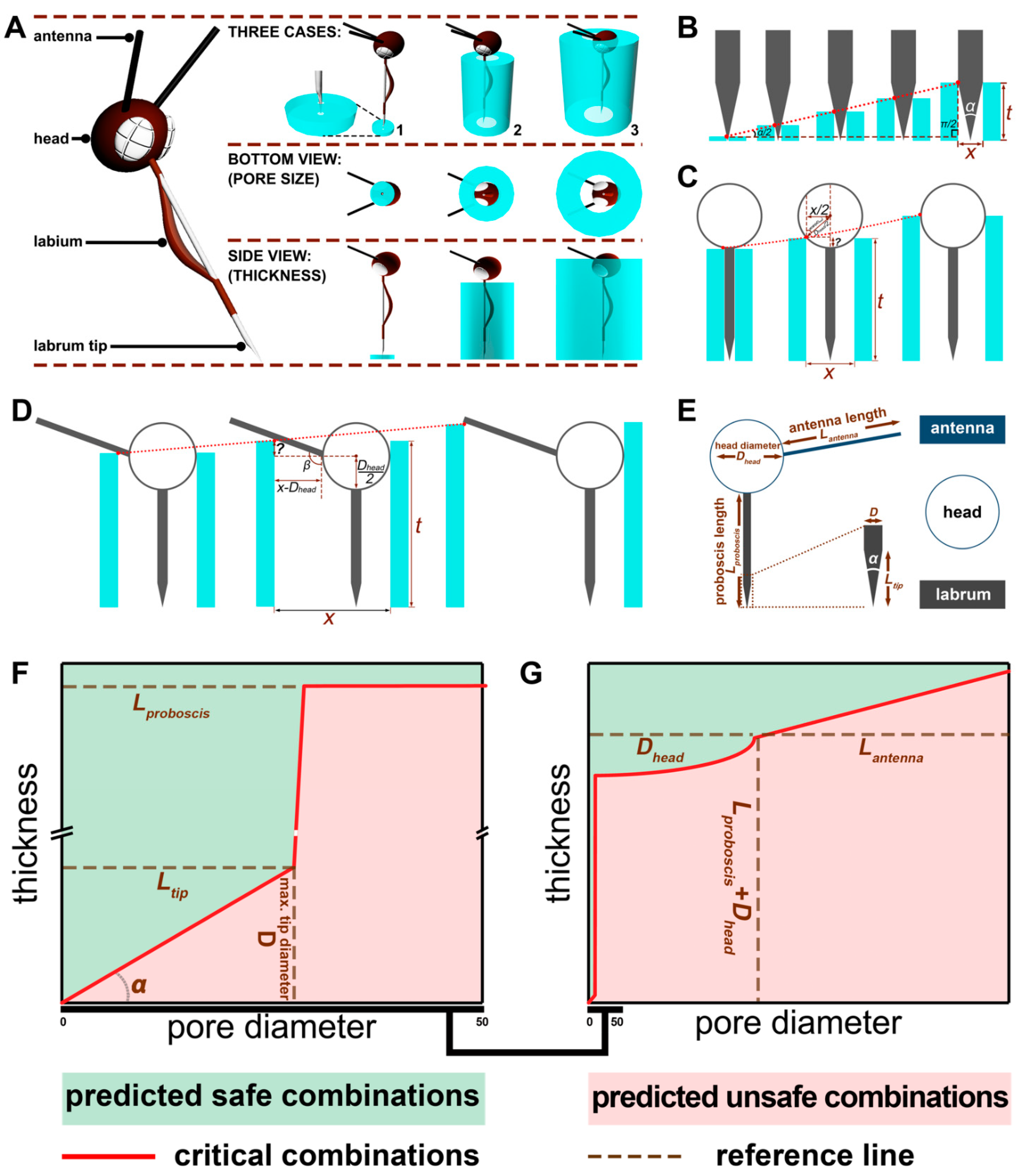
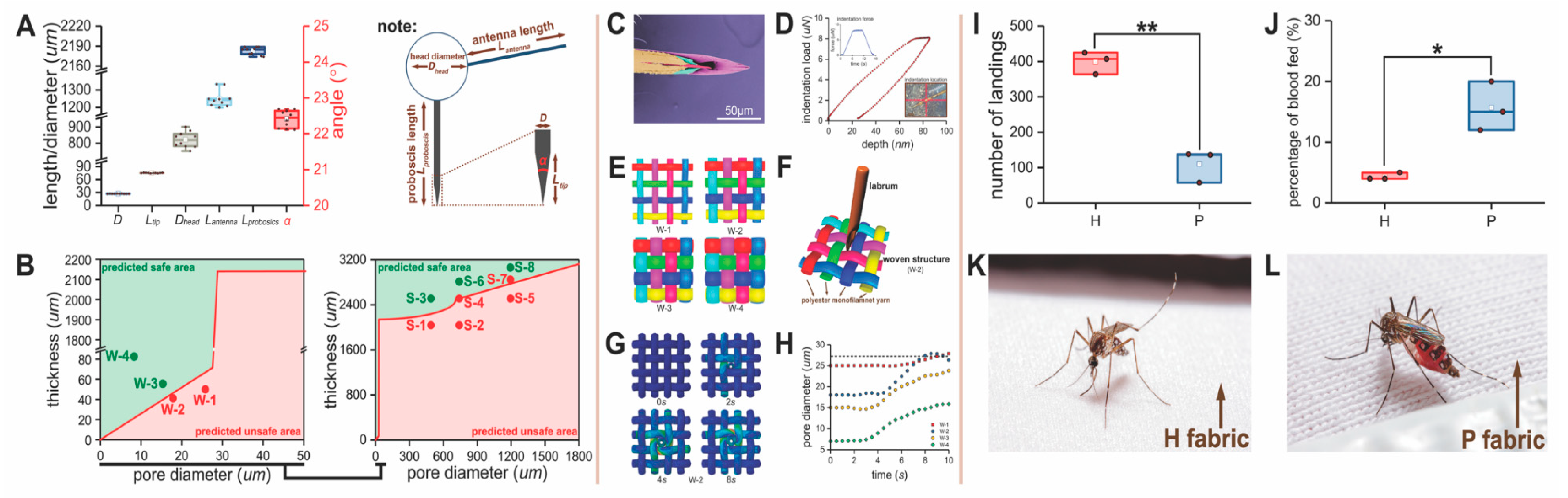
2.5. Model Rationale and Mosquito Morphometrics
Blood feeding of mosquitoes on humans involves physical interactions between the mosquito’s external morphology associated with the head and exposed skin, requiring a combination of insect behaviors allowing the mouthparts to penetrate the cornified, squamous epithelium and insert into the host blood vessels near the skin surface. When a textile is placed over the skin, the fabric restricts access to the skin and affects mosquito landing and probing behaviors. This creates another compliment of physical interactions between the textile and the mosquito that affects differently how the mosquito also interacts with the skin below. These physical parameters of the mosquito’s head and mouth parts impose three-dimensional limits, defined by their shape and size, on a mosquito’s ability to penetrate the textile and the skin. Understanding these limits and the mechanics of biting affected by the physical structure of cloth and the morphometrics of the mosquito’s feeding structures can be used to develop textiles to optimally resist blood feeding, as well as providing optimal comfort without the need for insecticides or repellents.
The mosquito proboscis (
Figure S1A,B) is a collection of interlocking needle-like mouthparts (stylet in shape) covered by a sheath, the labium. The stylets consist of the labrum (
Figure S1C,D), a pair of mandibles, a pair of maxillae, and a hypopharynx extending from the floor of the mouth between the mandibles and maxillae. The rigid, pointed labrum tip is shown in
Figure S1D and is the first part of the proboscis that makes contact with skin to initiate biting. The other mouth parts are used to advance the insertion into the skin and for channeling blood to the mouth. Preventing labrum penetration and/or contact with the skin prevents blood feeding.
Our model to describe the physical interactions between a mosquito and a barrier material is divided into three Cases that represent the process of fabric penetration to obtain a blood meal and how the mosquito interacts with different textile surfaces. For our Case 1 model (
Figure 1E), the dimension of the labrum (the largest mouthpart needed for penetration of the skin and blood feeding) is a critical attribute of the mosquito’s mouthparts. To measure its dimensions, the labrum from 20 adult female mosquitoes (described before) was dissected using needle-point forceps, then gold coated using a SC7620 Mini Sputter Coater (Quantum Design GmbH, Darmstadt, Germany), visualized using a Phenom G1 desktop scanning electron microscope (SEM; Thermo Fisher Scientific Inc., Waltham, MA, USA) in the Phenom SEM and Forensic Textile Microscopy Laboratory at NC State University, and the measurements of maximum labrum diameter (D), labrum tip angle (
), and tip length (
Ltip) taken from these images. To avoid body shrinkage from dehydration, the mosquitoes were killed by freezing, and the mouth parts were quickly dissected and gold coated.
For the model for Case 2 and Case 3 (
Figure 1E), 20 adult females were used for measurements of the head diameter (
Dhead) and antenna length (
Lantenna), not including the flagella branches and proboscis length (
Lproboscis), using a Nikon SMZ-1000 Zoom Stereo Microscope fitted with an ocular micrometer (Nikon Metrology, Inc., Brighton, MI, USA) in the Phenom SEM and Forensic Textile Microscopy Laboratory at NC State University. To avoid body shrinkage from dehydration, the mosquitoes were killed by freezing and then morphometric measurements were immediately taken. The mosquito anatomy that was measured is shown in (
Figure S1B,C).
2.6. Model Development
Based on observations of mosquito probing and biting behavior, we hypothesized that the morphometrics critical for blood feeding were associated with the head size and length, the relationship of the antennae to the head, and the length and diameter of the labrum. Based on these assumptions, there were three rationales on how a textile might be used to prevent penetration of the skin: (i) a barrier that is thick enough to prevent the labrum from reaching and penetrating the skin; (ii) a barrier with small enough pores that prevented the labrum and/or the head from penetrating the surface of the textile; and (iii) combinations of (i) and (ii). The boundaries for thickness based on our morphometrics were set from 0 to 2.95 mm (the sum of the head diameter and proboscis length) and the boundaries for pore diameter were from 0 µm to 1.8 mm (the sum of the antenna length and head diameter). Due to the complex geometry between the head and proboscis, we specified three cases to achieve a bite-resistant structure: pore diameter smaller than the diameter of the labrum, pore diameter smaller than the head diameter, and pore diameter smaller than the sum of the head diameter and antenna length. In those cases, each pore diameter has a specific thickness determined by the geometry of the mosquito mouthparts, head, and antenna that would impact biting.
The bite-resistance model describing the relationship between the pore diameter and thickness of a textile barrier is shown in
Figure 2B–D. In Case 1, the critical trajectory of the combination of pore diameter and thickness is the hypotenuse of a right-angled triangle (the longest side) of the labrum. In Case 2, the critical factor is the arc determined by the head shape. In Case 3, the critical factor is a straight line governed by the antenna. Based on this geometry, we defined the mathematical relationships for each case.
2.7. Materials for Model Validation
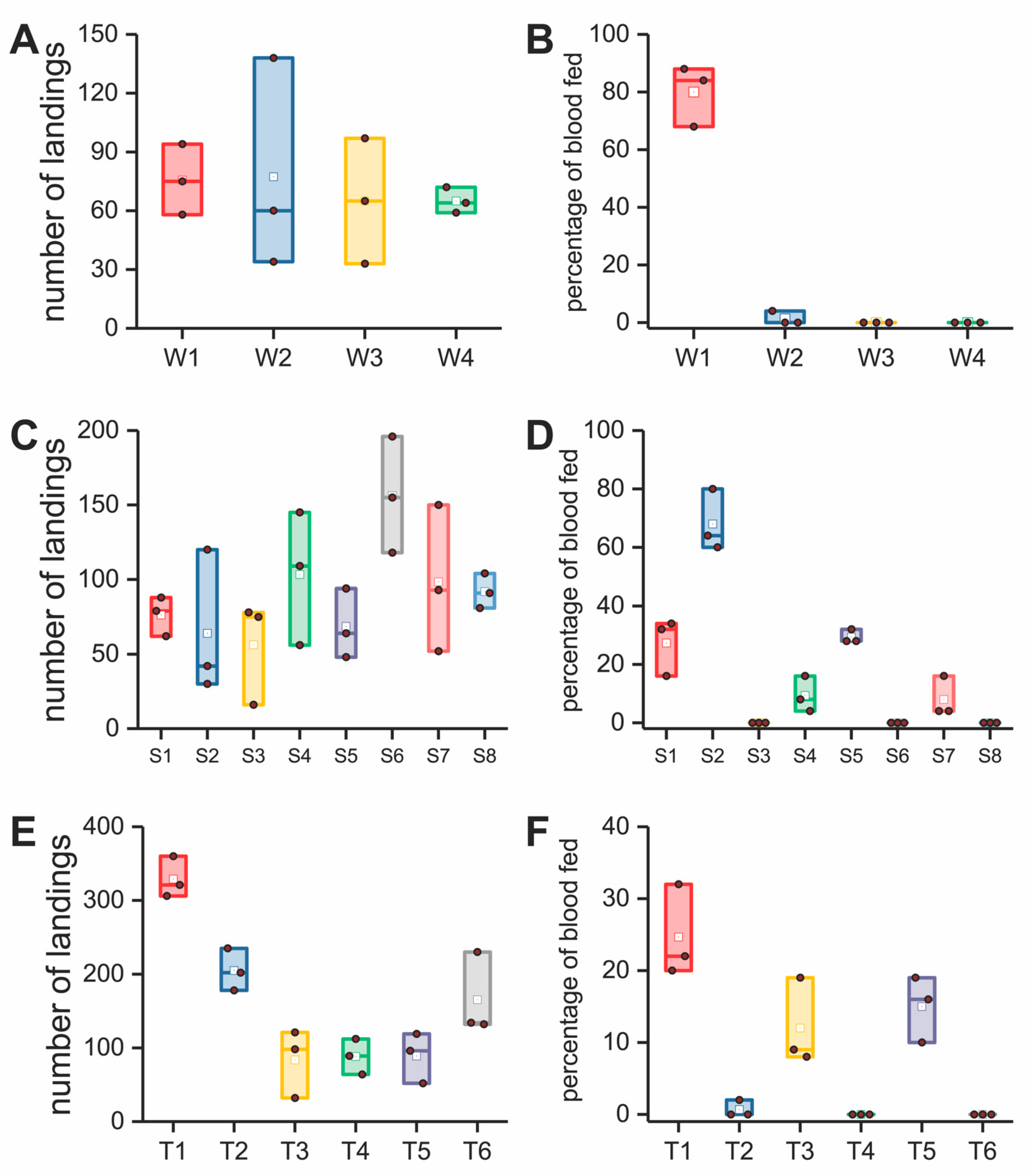
2.7.1. Stable Structures
Due to the sophisticated interlacement and entanglement of the fibers [
22], most textiles have irregularly distributed pores of different shapes and area and an uneven thickness. In terms of the latter, a textile never has an absolute planer surface. Because of this variability, relating textile structure to bite resistance is not precise. This is further complicated by the large variety of possible textile structural parameters that can be selected, including yarn denier, covering rate, surface roughness, weave or knitting density, etc. Therefore, the use of a textile with a single pore shape and size and a single, fixed thickness is challenging and requires testing a vast number of iterations using different textile production methods. Instead, our first step in model validation was the use of stable structures.
For Case 2 and Case 3 conditions, we simulated a porous fabric with rigid polypropylene plates (
Figure S2C) with bored holes of varying diameters that were distributed in uniform patterns on each plate where we could simulate precise pore shapes (circular), pore areas, and textile thicknesses. The size of each polypropylene plate was fixed at 14.5 cm × 3.4 cm to fit into the
in vitro bioassay device described earlier. Based on mosquito morphometrics, we focused on 3 different pore diameters which (i) included the head (1.25 mm); (ii) partially excluded the head (0.8 mm); and (iii) completely excluded the head (0.5 mm). Those plates were produced by a combination of 3D printing to obtain the correct thickness and computer numerical controlled (CNC) machining to obtain a specific pore size and number of holes. First, a plain mold was printed on a 3D printer (Objet Connex350, Edward P. Fitts Department of Industrial and Systems Engineering, NC State University, Raleigh, NC, USA) to the desired thickness. Then the pre-designed pattern was processed on a CNC machine to obtain holes with precise diameters that would mimic a porous textile. A series of prototype spacers (S = plastic spacer; S1, S2…, S8, listed in
Table 1) were made at different combinations of pore sizes and thickness, which spans Case 2 and Case 3’s safe and unsafe combinations. As shown in
Figure S5C,D, S1 is 2.1 mm thick, with a 0.5 mm pore diameter; S2 2.1 mm thick, with a 0.8 mm diameter; S3 2.5 mm thick, with a 0.5 mm diameter; S4 2.5 mm thick, with a 0.8 mm diameter; S5 2.5 mm thick, with a 1.25 mm diameter; S6 2.72 mm thick, with a 0.8 mm diameter; S7 2.75 mm thick, with a 1.25 mm pore diameter; and S8 3 mm thick, with a 1.25 mm diameter.
The holes in each plate were of uniform diameter. The ratio of open space (from the pores) to closed space (from the solid surface) was held constant in these studies. If the number of pores per plate was held constant but pore diameter increased, there would be an increasing probability that the probing mosquitoes would encounter a pore by chance alone. Furthermore, differences in the open area across a plate affects the amount of mosquito attractants (heat and odor [
23]) penetrating through the holes in the plate. These attractants can affect landing and biting rates. Accordingly, as pore diameter was increased, a smaller number of pores were needed per plate. If the number of pores is designated as
N and the diameter of a pore is designated as d with a unit of cm, the percentage of open area in a spacer should be a constant
C, as shown in Equation (1):
To keep the probability of a mosquito encountering a pore constant, the equation shows that the number of pores N in a spacer is inversely proportional to the square of the diameter of a pore, d. From the equation, the value of N was 572, 1396, and 3574 for pore diameters at 1.25, 0.8, and 0.5 mm, respectively.
For the Case 1 barriers, constructing thin plastic plates of ~75 µm or less by 3D printing was not possible. The thickness was too variable across the area of the plate. Furthermore, drilling small pores of ~28 µm or less by drilling across a thin plastic plate was not possible. To achieve the operational parameters needed to test the Case 1 model, commercially available Saatifil
® polyester woven filtration fabrics were used (W = woven; W1, W2, W3, and W4, listed in
Table 1) (shown in
Figure S2B). In
Figure S5A,B, W1 is 52 µm thick with a 25 µm pore dimeter, W2 is 60 µm thick with an 18 µm diameter, W3 is 58 µm thick with 14 µm pores, and W4 is 86 µm thick with 8 µm pores. These fabrics had square pores produced when the polypropylene monofilaments were woven in a plain weave pattern. The size of each woven fabric was 14.5 cm × 3.4 cm to fit into the
in vitro bioassay device already described. We evaluated the bite resistance of four monofilament woven fabrics and the plastic blocks using the
in vitro bioassay described earlier.
2.7.2. Knitted Textile Structures
To further validate our model for flexible textiles (T = textile materials;
Table 1), we constructed fabrics including one predicted unsafe and one predicted safe according the model for each Case.
Case 1: The Case 1 fabric (T1;
Figure S2D) was an ultra-fine synthetic knit of 80 percent polyamide of 20 denier count (a unit of measure for the linear mass density of fibers, the mass in grams per 9000 m of the fiber) and 20 percent elastane of 15 denier count and has a weight of 82 g/m
2. Its pattern was a jersey plated knit structure of 78 wales and 104 courses per inch and with a pore size between 32 and 42 µm. The pore diameter of T1 in
Figure S5F was larger than the diameter of the mosquito labrum. To reduce the pore diameter based on our Case 1 model, we used a 1 m-wide, laboratory oil-heated Stork laminator (Stork GmbH, Bavaria, Germany) to heat set the fabric in the Dyeing and Finishing Pilot Plant at NC State University. The temperature was 190 °C (lower than
Tg of the polyamide) with a 120 s duration. It was found that the pore diameters of the fabric (T2) was reduced by this treatment to 10 µm from 16 µm and the thickness reduced to 0.26 mm, as shown in
Figure S5E,F (predicted to be safe by the Case 1 model).
Case 2: 3D spacer fabrics (T3, T4: satin weave + pillar stitch;
Figure S2E) were produced on a double-needle bed, Raschel warp knitting machine with six guide bars (Rius Mini-tronic Raschel Warp Knitting Machine, RIUS-COMATEX, Barcelona, Spain) in the Knitting Laboratory at the Wilson College of Textiles at NC State University. The material consisted of 100% polyester (Huizhou City Meilin Textile Co., Ltd., Huizhou, China). For the pile yarn, a 33 dtex (a unit of direct measure of yarn linear density, grams per 10 km of yarn) monofilament was used. The outside surface was made with 55 dtex multi-filaments. Both multi-filaments contained 36 filaments, respectively. To make variations in the design, the take-up speed was changed. Hence, the stitches per cm and the thickness would change. The T3 fabric was made by a 700% take-up speed, and the T4 one made by a 900% take-up speed. The combination of thickness and pore diameter of the T3 (
Figure S5E,F) was predicted unsafe while that of T4 was predicted safe.
Case 3: The 3D spacer (warp) knit fabric for Case 3 had the same pattern and materials as the Case 2 fabrics, which were produced on the same Raschel warp knitting machine. Case 3 fabrics T5 and T6 (
Figure S2E) were produced at 1500% and 1200% take-up speeds. The T5 thickness was 2 mm with a pore diameter of 940 µm. T6 was 3 mm and 770 µm, respectively (
Figure S5E,F). Based on the model prediction, T6 is a safe material that should resist mosquito bites.
We evaluated the bite resistance of the Case 1, Case 2, and Case 3 fabrics using the
in vitro bioassay system described earlier. All the materials used in the model validation, as listed in
Table 1, including the woven textiles, plastic plates, and knits, were white in color to avoid potential mosquito preferences in landing and biting based on color differences.
2.8. Finite Element Model for Proboscis Penetration
In addition to our Case 1–3 conditions, we needed to investigate the point of contact of the proboscis to a textile surface and how this specific interaction might impact our prediction of penetration (especially relative to the Case 1 model). The finite analysis model was necessary because for Case 1, predictions based on labrum diameter alone were not 100% correct in predicting blood feeding when approaching the boundary between safe and unsafe textiles (
Figure 3B). This result suggested additional physical interactions might be in play that were important in preventing biting. Finite Element Analysis was conducted for a woven versus a knitted structure to examine two possible scenarios for micro-deformation. The woven model was used for investigating the interaction of the woven structures and the knit to understand the role of stretching.
Structural parameters of woven and knit structures were obtained by the calculation of fabric thickness, weave density and spatial axial distribution [
11,
24], which were then imported into SolidWorks
®, a computer-aided design program, for establishment of a geometrical model. The boundary conditions of both the woven and knit model were set to periodical boundary conditions [
25] for approximating a large (infinite) fabric piece by using a small fraction of the piece. Since only a small force is applied in both scenarios, the mechanical property for the knit and woven model can be treated as linear elastic materials.
To simulate the pore deformation of the woven structure, a virtual labrum with the same mechanical properties and shape of a real mosquito labrum was used to penetrate the woven fabric. This virtual labrum will be discussed more later. The test was analyzed using the software suite SIMULIA Abaqus/Explicit 6.14. The elastic modulus and Poisson’s ratio of the polyester monofilament used in this model were 2.16 GPa and 0.3, respectively.
For modelling the virtual labrum, we needed the fundamental mechanical properties of the proboscis. Because of its small size, traditional methods to measure tensile and compression [
26] were not possible. Alternatively, the elastic properties of the proboscis were determined with a Bruker Hysitron TI980 Triboindenter (in the NC State University Analytical Instrumentation Facility). The measured location and load–depth curves are shown in
Figure S7C. The elastic modulus of the proboscis can be achieved by the initial part of the recovery curve [
27].
To simulate the pore deformation of the knit structure, virtual tensile forces were applied to the model in the course and wale directions (
Figure S7B), and the simulated deformations compared with the real fabric deformation (
Figure S7D,E). The elastic modulus and Poisson’s ratio of the blended yarn used in this model were 1.08 GPa and 0.21, respectively. The knit model was validated using the experimental tensile data (
Figure S7C) to ensure they have an equivalent mechanical property as the real knit fabrics.
2.9. Prototype Bite-Resistant Fabrics Tested for Garment Construction
Three knitted fabrics (H, B, S;
Table 1 and
Figure S3B–D) were developed as component textiles for garment construction. They were selected from a dataset of candidate bite resistant fabrics that were predicted safe by our bite-resistance model. These textiles were assayed using arm-in-cage bioassays since the goal later was to test them in garments on human subjects in walk-in-cage studies.
Case 1 H. The Case 1 fabric H (the high-density fabric, H;
Figure S3B) was an ultra-fine synthetic knit of 80 percent polyamide of 20 denier count and 20 percent elastane of 20 denier count and had a weight of 96 g/m
2. Its pattern is a jersey plated knit structure of 84 wales and 112 courses per inch and with a pore size between 20 µm and 28 µm, allowing air passage but preventing mosquito biting. It had a high elasticity of 400% stretch in the course direction and 160% stretch in the wale direction (
Figure S7C). The H fabric has a more elastane content and smaller pore size compared with T1, which came from the same knitting technology. It was made into a base layer in the following section “construction of protective garments”. Although the H fabric was not a 100% bite-resistant material due to an irregular pore distribution in the knit pattern, when combined as a base layer with military issued garments, a 100% bite resistance was possible in whole-garment testing.
Case 1 B. Fabric B (a bonded fabric;
Figure S3C) is the combination of two layers of H fabric that was made by applying a small dot pattern of dry low-melt adhesive (CG-1698 polyurethane adhesive, Chemix Guru Ltd., Taichung, Taiwan) to one surface and then feeding the two fabrics back-to-back together applying pressure using heated drums (temperature 120 °C, duration 20 s). The two fabrics are fused together at regular intervals, and then the adhesive dots subjected to cool circulating air for 24 h to eliminate volatiles that might affect mosquito biting. The paste dot application procedure is particularly gentle to the substrate, and the wide range of options for formulating the paste provides the user flexibility in the application procedure. The relative nature, drape, porosity, and flexibility of the fabric is maintained, and this method only adds approximately 5% to the total weight. The B fabric is highly stretchable and demonstrated high mosquito bite resistance, which makes it suitable to being used as an outer protective garment.
Case 2 S. The S fabric (3D spacer fabric;
Figure S3D) was a commercially available 3D warp knit spacer fabric (Production ID: 34836, Springs Creative Products Group, LLC, Rock Hill, SC, USA) that was predicted safe for bite protection using our Case 2 model. The surface (top and bottom) yarns are PA filament tows, and the pile yarns used in the middle layer were PA monofilaments. The surface patterns are shown in
Figure S3D. The S fabric had a stable structure with large openings outside that allowed air flow into and under the garment, thereby transporting of heat and sweat out.
Case 3. Case 3 fabrics were translucent due to their large pores and not practical when used alone for typical garments where human body parts need to be covered and not seen by others. Therefore, we did not use the Case 3 fabrics to assemble a garment. This is not to say this fabric does not have uses for mosquito protection in parts of the body where it is ok to show the skin or as a cover at the beach or in the tropics where there are mosquitoes and also high thermal challenges to the body. The materials could also have uses for garment ventilation in specific areas of a garment.
Base on the color requirement for military garments, the H fabric was dyed to a light brown color before assembly into the base layer. B and S were dyed to a camo color before assembly into the military-style shirt (NCSU shirt).
2.10. Textile Structural Analysis
As mentioned before, fabric pore size and thickness are two critical factors in our model that determined bite resistance. Hence, it was important to measure these variables accurately. Pore areas in textile materials, especially in knitted fabrics, have irregular shapes due to complex fiber configurations. Pores with an elliptical shape often failed to resist mosquito bites even though the pore openings were narrower than the proboscis in one direction. We also found irregular pore openings were difficult to measure accurately and were not informative to our model. Therefore, we assumed pores to be circular, and we measured pore diameter across the widest area of fabric pores so that the model would reflect a worst-case scenario.
Pore diameter was measured (
Figure S4) with a digital microscope (Bausch & Lomb, Monozoom-7 Zoom Microscope), and images analyzed using ImageJ software, an open-source image-processing program designed for analyzing multidimensional images [
28]. Based on Feret’s diameter, the width of the pore along its longest direction, a frequency distribution of the pore diameters, and a fitting curve were obtained. From the peak of the fitting frequency distribution, we picked three maximum diameters for each fabric to calculate the average maximum pore diameter (4 images were captured for each fabric, a total of 12 measured values). Fabric thickness, measured with a Thwing-Albert ProGage Thickness Tester (Thwing-Albert ProGage instrument company, West Berlin, NJ, USA) was averaged over 10 tests, using standard methods for assessing textile thickness, as described in the ASTM D1777 guidelines [
29]. The procedure of measuring pore diameter is shown in
Figure S4, and the values of the measured pore diameters and fabric thicknesses are shown in
Figure S5.
2.11. Comparison of the Non-Insecticide and Insecticide-Treated Textiles
Before garment construction, it was prudent to understand how our bite-resistant, non-insecticidal textiles performed relative to a leading brand of insecticide-treated cloth. We compared the bite resistance of the H fabric with a commercially available permethrin-treated T-shirt fabric (P = permethrin, listed in
Table 1), which was cut from an InsectShield
® T-shirt (RN149846, Insect Shield, LLC, Greensboro, NC, USA) purchased from a local retail store. The fabric was 70% cotton and 30% polyester and cut into 14.5 cm × 3.4 cm for the arm-in-cage (in vivo) bioassays.
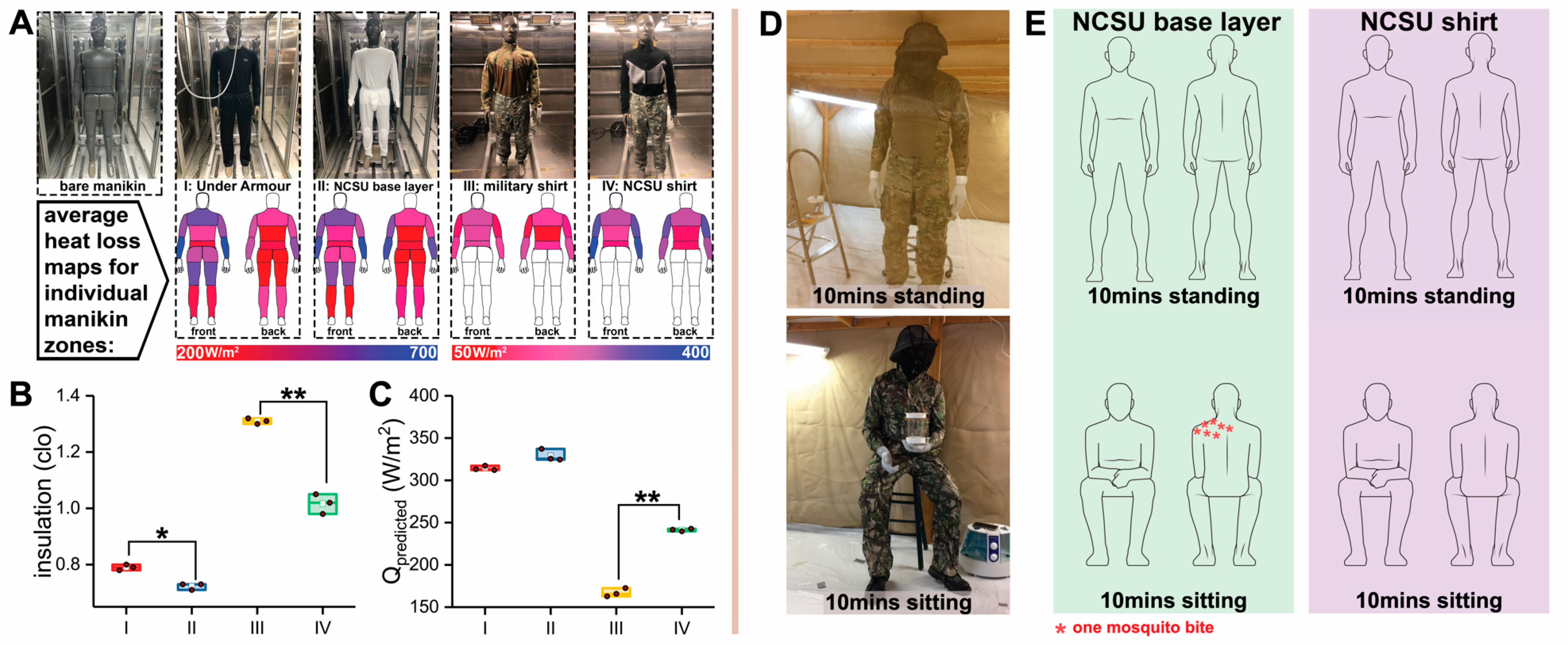
2.12. Construction of Protective Garments
Based on the predictions of our model, three types of fabrics were used as bite resistant materials: a superfine knit fabric (H), a double-layer bonded knit fabric (B), and a knitted 3D spacer fabric (S), as shown in
Figure S3B–D. Two types of garments were produced: a base layer and a military-style combat shirt, as shown in
Figure S6A,B.
Base layer (
Figure S6A). A form-fitting undergarment was constructed consisting of an upper body, form-fitting garment having a torso section and arm sections made from the Case 1 fabric H. The garment was fitted with an elastic neck cuff secured to define a neck opening for the torso section; an elastic waist cuff secured to define a waistband around the torso section; and a pair of elastic wrist cuffs disposed at an outer terminus of each of the arm sections. The ensemble also included a lower-body, form-fitting garment having a waist section and left- and right-leg sections made from the same textiles as previously described for the shirt. The pants were fitted with an elastic waist cuff secured to define the waistband around the waist section and a pair of elastic ankle cuffs disposed at the terminus of each of the left and right leg sections. The cut and sewing of this garment were conducted in the Fashion Studio at the Wilson College of Textiles at NC State University. The garment was unwashed and tested in walk-in-cage studies (described earlier).
NCSU shirt (
Figure S6B). A long sleeve shirt was constructed as an upper-body, form-fitting garment. The shirt consisted of Case 1 B and Case 2 S fabrics. The incorporation of the B fabric provides extensionality and bite resistance, while the use of the S fabric brings breathability, pressure release, and bite resistance to the shirt. The S fabric was designed into the sections of the shoulders, chest, back, and elbow of the garment, and the remainder of the shirt was the B fabric. The cut and sewing for this garment were conducted in the Fashion Studio at the Wilson College of Textiles at NC State University. The garment was unwashed and tested in walk-in-cage studies (described earlier).
Both garments were sewed on an MF 7924 cover stitch sewing machine (JUKI, Singapore) and locked on a DDL-8700-7 lockstitch machine (JUKI, Singapore). The sewing thread was 100% polyester (RCL, model: RCLJ-ST-W, Wuxi, China). The seams were bite resistant in the walk-in-cage bioassay, since there was a two-layer overlap of the textile at the connections between the two pieces of cloth.
2.13. Sweat Manikin Test for Comfort Evaluation of Garments
In the Textile Protection and Comfort Center of NC State University, a sweating manikin was used to evaluate the thermal insulation and breathability of the garments [
30] (
Figure S6D). The test instrument is composed of a manikin, an environmental chamber, an ambient detector, a power supplier, a water reservoir, and a pump.
Comparisons were made with a commercially available base layer garment (Under Armour® men’s base 1.0 crew, model: 1281079, Under Armour Inc., Baltimore, MD, USA) and a military-issued combat shirt (Winter Army Combat Shirt Test, made in the USA by NIB/NCW, Figure 5A). The comparison garments had similar material characteristics and knit patterns to our garments. Each comfort evaluation was replicated three times, after which average values were calculated.
Manikin zones (a group of thermal-sweat elements on the manikin) were measured for thermal resistance and evaporative resistance. The standard method for measuring thermal resistance is described in ASTM F1291 and was followed. Test conditions for thermal resistance were 20 °C, 50% relative humidity, and a 0.4 m/s air speed with a 35 °C skin temperature. The measurement standard of evaporative resistance was ASTM F2370. Test conditions for evaporative resistance were 35 °C, 40% relative humidity, and a 0.4 m/s air speed with a 35 °C skin temperature. The following parameters were obtained from the manikin test:
Rt (°C·m
2/W), the total thermal resistance provided by the manikin, garment ensembles, and air layer;
Ret (kPa·m
2/W), the total evaporative resistance provided by the manikin, garment ensembles, and air layer;
Rcl (°C·m
2/W), the instinct thermal resistance provided by the garment ensembles only;
Recl (kPa·m
2/W), the instinct evaporative resistance provided by the garment ensembles only;
It (clo), the total insulation provided by the manikin, garment ensembles, and air layer (higher
It values mean the garment has a higher thermal insulation property that would not be desirable in warm weather for a bite-resistant fabric);
im, the moisture-heat permeability through the fabric on a scale of 0 (total impermeable) to 1 (total permeable) normalized by the permeability of still air on the naked skin; and
Qpredicted (W/m
2), the predicted heat loss potential, which gives a predicted level of the total amount of heat that could be transferred from the manikin to the ambient environment for a specified condition. The
Qpredicted incorporates thermal and evaporative resistance values to calculate the predicted levels of evaporative and dry heat transfer components for a specific environmental condition. In this case, the specified environment was 25 °C and a 65% relative humidity. The overall
Qpredicted under these conditions was calculated by adding the predicted dry component of heat loss to the predicted evaporative component of heat loss and reflected the predicted total amount of heat loss possible. The test results of all parameters are shown in
Table S1.
2.14. Data Analysis
All the replicated data for the assays and comfort analyses (
Figure 3,
Figure 4 and
Figure 5 and
Figure S5) were plotted in ORIGINPRO
® 2018 using a box plot format, a graphical format that summarizes the key statistical values. The solid brown dot in the box plot was the raw data. The height of the box represents the 25th and 75th percentiles. The whispers represent the 5th and 95th percentiles. Additional values included the median (line inside of the box) and mean (white dot) presented in the box plot. We used the mean value of each data set for our analyses.
We used one-sample Student’s
t-tests to investigate the significance between two data sets in
Figure 3I,J and
Figure 5B,C The mean value of the first data set was used as the theoretical expectation. The second data set was set as the true mean. Differences in mean values were found to be statistically significant when the
p values were greater than 0.05 (*) or 0.01 (**).
All tested materials and garments are listed in
Table 1, including information on the material type, name, abbreviation, thickness, pore diameter, model prediction, and bioassay validation. Values of thicknesses and pore diameters are the mean values calculated from the multiple measurements discussed in the section “Textile structure analysis”. Model prediction is the predicted bite resistance. “Safe” represents a fabric that is predicted to have 100% bite protection predicted by the bite-resistance model and “unsafe” means the fabric is predicted to allow at least 1 mosquito bite. Bioassay results are actual measurements of bite resistance. “Pass” indicates the fabric was at least 95% bite resistant by the in vitro or in vivo bioassay. “Fail” indicates a fabric provided less than 95% bite protection.