Abstract
The oil film generation of a U-cup rod seal and the oil film thickness on the rod after outstroke were analyzed analytically, numerically, and experimentally. The analyzed sealing system consists of an unmodified, commercially available U-cup, a polished rod, and mineral oil. The inverse theory of hydrodynamic lubrication (IHL) and an elastohydrodynamic lubrication (EHL) model—both based on the Reynolds equation for thin lubricating films—were utilized to simulate the oil film generation. In the EHL analysis, physical parameters and numerical EHL parameters were varied. Both the analytical and numerical results for the varied parameters show that the film thickness follows a square-root function (i.e., with a function exponent of 0.5) with respect to the product of dynamic viscosity and rod speed, also referred to as the duty parameter. In comparison to the analytical and numerical results, the film thickness obtained via ellipsometry measurements is a function of the duty parameter with an exponent of approximately 0.85. Possible causes for the discrepancy between theory and experiments are discussed. A potential remedy for the modeling gap is proposed.
1. Introduction
The lubrication conditions in the sealing gaps of rod seals have a significant influence on friction, wear, and leakage. A thicker oil film reduces friction and wear but can result in leakage if it is wiped off at instroke. The oil film generation must be considered in the development process of rod seals to achieve optimum lubrication conditions as well as leak-tight operation [,,].
The oil film generation depends on operating conditions [,] and seal geometry [], as well as seal material properties []. Using a method based on ellipsometry, it was found that the oil film thickness in the sealing gap of typical polyurethane U-cups is only in the sub-micrometer to nanometer scale [,].
Empirical studies on rod seals and film thickness measurements require substantial experimental effort and thus great financial expense. With hundreds of different possible seal designs, materials, and operating conditions in various applications, predicting the lubrication conditions of rod seals using models greatly reduces empirical expense.
State-of-the-art simulation models for analyzing reciprocating seals are based on the two main approaches: the theory of elastohydrodynamic lubrication (EHL) [,,] and the inverse theory of hydrodynamic lubrication (IHL) [,,,]. In an EHL problem, both the hydrodynamic pressure and the film thickness are determined simultaneously. In contrast, the IHL assumes a hydrodynamic pressure distribution and uses it to determine the film thickness. The IHL theory was developed by Blok [].
Both analysis approaches are based on the Reynolds equation for the combined pressure and shear flow in thin lubricating films:
Equation (1) involves the length coordinate , the hydrodynamic pressure , the film thickness , the fluid density , the dynamic viscosity , and the sliding speed , which corresponds to the rod speed. Equation (1) is valid for a constant density and a constant dynamic viscosity of the fluid. The Reynolds equation is derived from the Navier–Stokes equations with certain assumptions. The equation is valid for hydrodynamic flows governed by friction and pressure forces in which inertia effects can be neglected. A useful control parameter to assess the validity of Equation (1) for a certain problem is the dimensionless Reynolds number
and the reduced Reynolds number
Equation (2) relates the inertia to the friction forces in the fluid. The reduced Reynolds number (Equation (3)) combines the Reynolds number with the gap ratio (gap height/gap length) and can serve as an advanced parameter to assess the validity of the Reynolds equation []. Inertia effects need to be considered when the reduced Reynolds number is of the order of 1 [,,].
Various empirical and theoretical approaches for analyzing the lubrication conditions of reciprocating rod seals are the result of decades of research [,,]. However, a standardized and widely used technique for film thickness measurements on reciprocating seals has not become established yet. Therein lies one of the most challenging tasks in the development process of advanced simulation models for practical relevant reciprocating rod seals: proper and reliable validation for typical operating conditions.
In this paper, three methods for analyzing the lubrication conditions of rod seals are presented. The film thickness on the rod after outstroke was measured empirically using ellipsometry as described in a previous paper []. Those film thickness measurement results for different rod speed values and viscosity classes are adopted for discussion and validation of two simulation models based on IHL and EHL. The oil film generation values were calculated using both simulation models for similar operating conditions and were used in the empirical study. The results reveal weaknesses of both frequently used simulation approaches. Furthermore, challenges in modelling the oil film generation of reciprocating rod seals are outlined and discussed.
2. Materials and Methods
2.1. Sealing System
The analyzed hydraulic-rod seal constitutes a tribological system with three main components: the seal element, the hydraulic oil, and the hydraulic rod (Figure 1). We used a commercially available U-cup with asymmetrical profile type T20 50 × 65 × 10 (Art. No. 40422194, Freudenberg Sealing Technology GmbH & Co. KG, 69469 Weinheim, Germany) based on a Shore 95 A polyurethane type 95 AU V142 []. This U-cup represents a typical seal element for standardized housings according to ISO 5597. The rod with a diameter of 50 mm was polished mirror-smooth, as is required for film thickness measurements using ellipsometry. Mineral-oil-based hydraulic oils were used. The dynamic viscosity of the oils was measured in a previous study [].
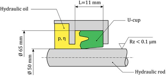
Figure 1.
Illustration and installation conditions of the analyzed rod seal.
2.2. Measurement Procedure for Seal Analysis
In this study, the sealing system was modeled as a two-dimensional cross-section. To this end, a geometric model of the seal’s cross-section was required as input. The minimum (inner) diameter of the U-cup was measured using the TESA Visio 300 GL video-based measurement machine (TESA SA, 1020 Renens, Switzerland). Afterwards, we embedded the U-cup seal in gypsum and cut it in a radial direction. The contour of the cross-section was then digitized based on multiple images taken with a Keyence VHX 3000 digital microscope (Keyence, Osaka, Japan). The roughness and contour of the sealing edge were analyzed in detail using a Keyence VK9710 laser-scanning microscope (Keyence, Osaka, Japan). Furthermore, the sealing edge and its material contrast were analyzed using a Phenom proX (Thermo Fisher Scientific, Waltham, Massachusetts, United States) scanning electron microscope.
2.3. Film Thickness Measurement Using Ellipsometry
Ellipsometry is an optical—and therefore contactless—measurement method for characterizing surfaces’ optical properties. One field of application is the measurement of thin layers or films on substrates in the nanometer []. Its precision makes ellipsometry suitable for the analysis of thin oil films on polished hydraulic rods [,].
The film thickness measurement procedure was carried out in three steps; see Figure 2. After outstroke ①, the rod was removed from the test rig without touching the remaining oil film on the surface ②. Then, using the ellipsometer, the oil film was analyzed around the circumference and in the axial direction to calculate the mean value ③. It must be noted that the thin oil film on the rod remains stable over hours, as was shown in previous studies []. Further details on the measurement procedure can be found in [,].
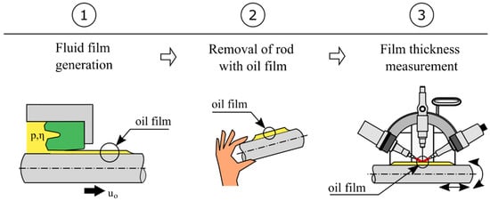
Figure 2.
Schematic illustration of the film thickness measurement procedure using ellipsometry.
2.4. Elastohydrodynamic Lubrication Analysis
In an elastohydrodynamic lubrication (EHL) analysis, the fluid film thickness and the hydrodynamic pressure in the lubricated sealing gap are determined. The calculation for the two quantities is formulated as a numerical fluid–structure interaction (FSI) problem. The balance of static and hydrodynamic load serves as an equilibrium condition for coupling the hydrodynamic and the structural mechanics models of the FSI problem.
The first governing equation is the Reynolds Equation (1) for thin lubricating films. The discretized Reynolds equation follows from Equation (1) by adopting a finite difference method according to [,]. In the solution procedure, the lubricant was modeled as slightly compressible with a bulk modulus of 108 Pa to improve the numerical convergence. Depending on the treatment of the negative pressure values throughout the iterative solution procedure, different cavitation models are obtained. In the Guembel cavitation model, the negative pressure values are excluded from the final solution at the end of the solution procedure. The grid points with a negative pressure value are set equal to the constant cavitation pressure. In the Swift–Stieber or Reynolds cavitation model, each iteration of the Jacobi method is checked for negative pressure values beneath the cavitation pressure, and these are excluded from the intermediate solution. For the same problem, both the Swift–Stieber and Reynolds cavitation models generally lead to a slightly higher hydrodynamic pressure compared to that of the Guembel cavitation model, see [].
The second governing equation is the film thickness equation:
Equation (4) involves the static contact geometry from a previous contact mechanics analysis, a minimal film thickness , and the difference between static and hydrodynamic film thickness . The film thickness difference is determined by the elasticity equation according to the elastic half-space theory for line contacts []:
The surface deflection in the normal direction at the location is calculated as the convolution of all pressure values at all locations .
The parameter is the reduced modulus of elasticity, which is calculated from the modulus of elasticity and Poisson’s ratio for both surfaces as follows:
The elastic modulus and Poisson’s ratio values for the elastomeric seal and the steel rod used in the EHL analyses are , and , , respectively. Equation (5) is solved using an FFT-accelerated technique according to [,].
The third and last governing equation is the load balance equation, expressed in terms of the line load as follows:
Equations (1), (4)–(6) are solved in a discrete manner on a numerical grid with a constant grid point spacing of 2.5 µm. In the current study, the forward iterative method proposed by Hamrock and Dowson [] is utilized for the solution procedure. A detailed derivation and a numerical implementation of the currently utilized solution procedure is provided by Dakov [].
The film thickness in Equation (4) and the pressure difference in Equation (5) are formulated in terms of the static contact geometry and contact pressure , which are determined in a static finite-element analysis (FEA) of the mounting process. In the FEA, a two-parameter Mooney–Rivlin hyperelastic model is used with and .
2.5. Inverse Theory of Lubrication
In IHL, the dynamic pressure distribution is approximated with the static pressure distribution . Thus, Equation (1) can be integrated over . Assuming a film thickness at the location of the maximum pressure (), the free constant of the integrated equation can be found. The resulting expression is as follows:
Figure 3 shows a hydraulic rod seal and rod at outstroke, including a detailed view of the sealing gap. The film thickness distribution , pressure distribution , and oil velocity profiles at specific points in the sealing gap are illustrated.
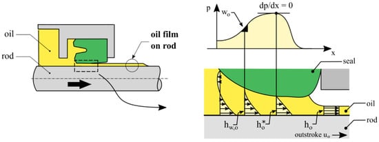
Figure 3.
Schematic illustration of a U-cup and oil film generation at outstroke.
Equation (8) is differentiated with respect to . Using this, the second derivative of the pressure with respect to the axial direction disappears () at the point of the steepest pressure gradient . The film thickness is calculated as follows:
Considering the conservation of mass, the oil film thickness remaining on the rod after outstroke is half the value of the film thickness at the pressure maximum where . Using this relation and after inserting Equation (9) in Equation (8), the following final expression is obtained:
The film thickness values in Equation (10) are formulated as functions of the rod speed , the dynamic viscosity , and the maximum pressure gradient at outstroke. The rod speed is specified by the test rig or the application. The dynamic viscosity can be determined using a rheometer. The static maximum pressure gradient in the sealing gap can generally be analyzed using a finite-element analysis and hydrodynamic corrections [,,].
3. Results
3.1. Analysis of the U-cup
An inner diameter of 49.37 mm was measured before installation. In addition, the cross-section of the seal was analyzed using microscopy. Based on the data from the microscopes and the measured diameter, the two-dimensional cross-section of the U-cup was generated as input for the simulation model. Figure 4 illustrates the cross-section of the seal.
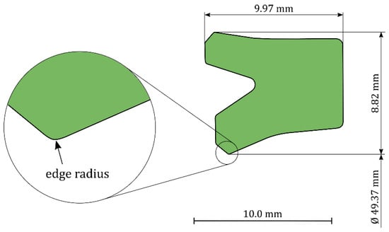
Figure 4.
Cross-section of the digitized U-cup.
Figure 5a shows a detailed view of the cross-section of the sealing edge taken with a laser scanning microscope. Figure 5b shows an image of the sealing edge taken with a scanning electron microscope in a radial direction. The analyzed U-cup does not have an ideally smooth surface, and thus the edge radius cannot be assigned a unique value. The corner radius r of the sealing edge was found to be in the range 10 to 30 µm.
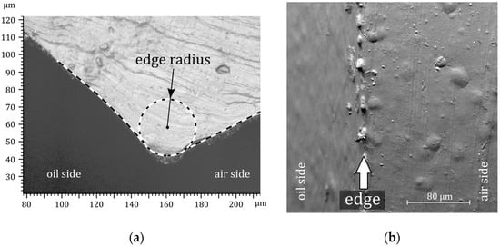
Figure 5.
Detailed views of the sealing edge: (a) cross-section with laser scanning microscopy and (b) top view with scanning electron microscopy.
3.2. Oil Film Generation
3.2.1. Gap Height at Outstroke and Instroke
The deformation of the U-cup and the static contact pressure distribution in the sealing gap after assembly were computed for a sealing-edge radius of 10 μm and 30 μm using FEA in the MSC Marc Mentat software. Figure 6 shows the deformed and mounted seal without an additional operating pressure for an edge radius of 30 μm. The assembly process results in a characteristic asymmetric pressure distribution with a steep pressure gradient on the oil side. A maximum pressure of 22.34 MPa and radial load of 409 N were obtained from the FEA. The contact geometry and the pressure distribution were used as input for the EHL simulations.
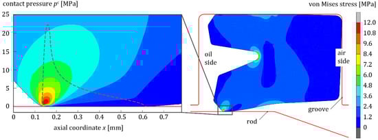
Figure 6.
Illustration of the mounted U-cup including a detailed view of the static contact pressure.
Figure 7 shows the pressure distribution and the gap height during outstroke (left) and instroke (right) as an example of specific operating parameters. Logarithmic (top) and linear (bottom) scales were used. Full lubrication was provided for both outstroke and instroke. It must be noted that starved lubrication can occur at instroke in practical hydraulic applications. The degree of lubricant starvation at instroke depends in part on the speed at the previous outstroke. However, the simulations at instroke serve only as examples for demonstration purposes. For the simulations, a dynamic viscosity of 0.25 Pa⋅s and a rod speed of 0.25 m/s were chosen. The directions of the rod velocities for outstroke and instroke are indicated.
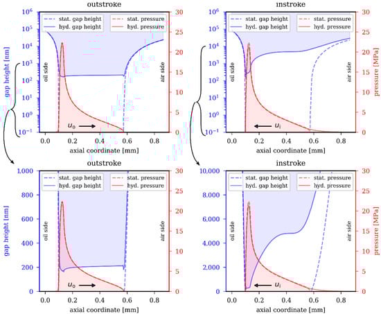
Figure 7.
Calculated film thickness (top: logarithmic scales; bottom: linear scales) and pressure in the sealing gap at outstroke (left) and instroke (right) using the EHL model (rod speed: 0.25 m/s; viscosity: 0.25 Pa⋅s; ambient pressure; full lubrication conditions).
The differences between the static and the hydrodynamic contact pressure are small, particularly at outstroke. The maximum pressure, maximum pressure gradient, and minimal film thickness are close at the oil side of the U-cup for both outstroke and instroke. At instroke, the gap height distribution is wedge-shaped. At outstroke, the film thickness is nearly constant along the axial direction. The film thickness in the sealing gap at the pressure maximum is 173 nm at outstroke and 291 nm at instroke. Minor oscillations in the film thickness along the axial direction were identified for the instroke and outstroke analyses; see Figure 7. In both cases—and relative to the direction of rod velocity—this region is located behind the pressure maximum where the pressure drops and the gap diverges. The specific location is at mm for outstroke and mm for instroke.
3.2.2. Duty Parameter
Figure 8a shows the computed film thickness on the rod after outstroke as a function of the rod speed. For the calculations, a sealing-edge radius of 10 μm and a dynamic viscosity of 0.064 Pa⋅s were chosen, which correspond to the dynamic viscosity of HLP ISO VG 32 at room temperature. Three maximum pressure gradients were chosen to calculate the film thickness on the rod using the IHL: Pa⋅m−1, Pa⋅m−1, Pa⋅m−1. Figure 8b shows the influence of the dynamic viscosity on the calculated oil film thickness. For the calculations, rod speed values of 0.12 m/s and 0.25 m/s were chosen. Further input data for the simulation, such as the elasticity parameters of the elastomer and the rod material, are provided in Section 2.3.
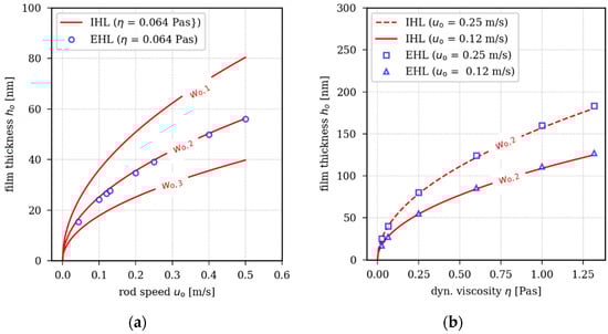
Figure 8.
Calculated oil film thickness at outstroke as a function of rod speed (a) and dynamic viscosity (b) using the EHL and IHL models ( Pa⋅m−1; Pa⋅m−1; Pa⋅m−1; ambient pressure; room temperature).
In both simulation models, the film thickness follows a square-root function of the product of rod speed and dynamic viscosity as given in Equation (11):
In the Reynolds Equation (1), the speed and the viscosity can be combined into a single parameter, also referred to as the duty parameter, which is defined as the product of two parameters. Figure 9 shows the calculated film thickness for different rod speed values and viscosities as a function of the duty parameter using a double logarithmic scaling. Figure 9 demonstrates that the fundamental relationship between film thickness and the duty parameter in the IHL and EHL is near identical. The film thickness calculated using the analytical IHL in Figure 9 appears as a straight line in the double logarithmic scale. The results obtained by using the IHL can be vertically shifted through variation of the maximum pressure gradient . For an assumed maximum pressure gradient of Pa⋅m−1 in the IHL analysis, the film thickness results of both simulation models are near identical.
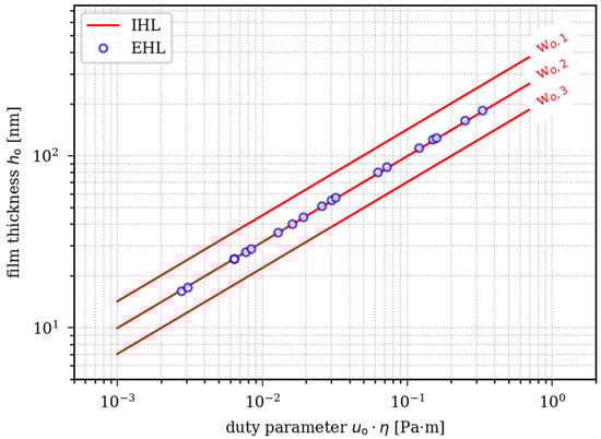
Figure 9.
Calculated oil film thickness at outstroke as a function of the duty parameter () using the EHL and IHL methods ( Pa⋅m−1; Pa⋅m−1; Pa⋅m−1; ambient pressure; room temperature).
3.2.3. Parameter Study
Besides the operating conditions, the calculated film thickness depends on the chosen material model, seal geometry, grid size, and cavitation model used. In a parameter study, we analyzed the influence of those model input parameters by modifying our initial simulation model. In each of the four new series of analyses, a single input parameter of the initial model was changed. Firstly, the elastic modulus of the elastomeric seal in the EHL was increased by 20%. To obtain correct EHL input parameters, a finite-element assembly simulation with 20% higher hyperelastic material parameters and was also carried out. Secondly, the edge radius was tripled from 10 µm to 30 µm. Thirdly, a coarser mesh was generated by doubling the grid spacing from 2.5 µm to 5 µm. Fourthly, the Reynolds cavitation model was implemented instead of the Guembel cavitation model.
The graphs in Figure 10 appear as straight lines with an equal slope in a double logarithmic scale. The slope is independent of the parameters under examination. For each parameter set, the film thickness as a function of the duty parameter can be fitted using a power model with an exponent . Only the constant depends on the actual input parameters.
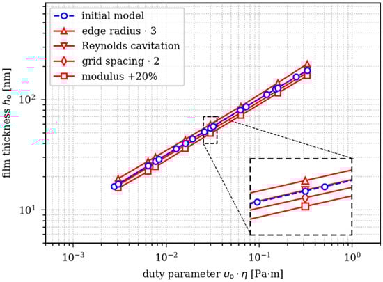
Figure 10.
Calculated oil film thickness at outstroke as a function of the duty parameter () using the EHL method and different model input parameters.
In Table 1, we list the calculated film thickness for two duty parameters (0.016 Pa⋅m and 0.158 Pa⋅m ) and various input parameters examined for the EHL simulation model. In our simulation model, no significant differences between the two cavitation models were identified. The difference in film thickness between both cavitation models is less than 1%. In contrast, the grid spacing of the simulation model, elastic modulus, and the radius of the sealing edge clearly influence the calculated film thickness. A grid spacing of 5 µm results in approximately 5% lower film thickness compared to that of the initial model with a spacing of 2.5 µm. With increasing elastic modulus, the calculated film thickness decreases. A 20% increase of the elastic modulus results in a film that is approximately 10% thinner. Tripling the sealing-edge radius increases the film thickness by approximately 10% compared to that of the initial model.

Table 1.
Parameter study on the influence of various EHL model input parameters concerning the absolute film thickness at outstroke.
4. Discussion
4.1. Profile Analysis
The analysis of the U-cup was carried out on different scales using light microscopy and a confocal microscope. The presented procedure for creating a geometric model of the U-cup can be applied to any rod seal. The main advantage is that this procedure does not require any CAD files of the geometry in advance and results in the exact contour of the analyzed seal element considering geometrical imperfections due to the manufacturing process. The detailed analysis of the U-cup’s sealing edge revealed an edge radius of approximately 10 µm to 30 µm. It remains a challenge to identify the exact shape of such a sharp sealing edge. The edge radius in this study was very low compared to that of other reciprocating seals such as O-rings or rectangular seals, for example, rectangular seals analyzed by Kanters et al. [] had a radius of 1 mm. The edge radius of reciprocating seals influences the oil film generation. Nikas and Sayles [] analyzed the influence of the corner radius in a range of 0.2‒0.5 mm on the film thickness of reciprocating stator and rotor seals in numerical terms.
Hörl [] confirmed the influence of the edge radius on the film thickness using ellipsometry and U-cups with edge radii of 40 µm and a 130 µm. The difference in the film thickness was around a factor of 2 to 3. Further challenges in modelling the edge radius occur due to the surface roughness, material inhomogeneity, and the non-idealized sharp contour. Due to its influence on the oil film generation, the exact geometry of the sealing edge is crucial for the accuracy of the simulation model and is to be accorded particular attention in further investigations.
4.2. Film Thickness Simulation
We presented three methods for analyzing the oil film generation of a commercially available U-cup rod seal: IHL, EHL, and film thickness measurements using ellipsometry. The oil film thickness on a polished rod after outstroke was determined for typical rod speeds and viscosities using all three methods. In the course of the fluid–structure interaction, the hydrodynamic pressure and film thickness are updated continuously. At instroke and outstroke, minor instabilities in the film thickness distribution occurred; see Figure 7. A similar result was described in [,] and related to numerical effects at locations with extreme pressure gradients. This hypothesis is supported by the observation in the current analysis that the instabilities at outstroke are far less pronounced than those at instroke. Similar to [], we assume that the instabilities do not have a considerable influence on the overall film thickness distribution and especially the gap height and the film thickness on the rod .
Under full lubrication and otherwise identical conditions, the film thickness at the maximum pressure at outstroke is thinner than at instroke; see Figure 7. It follows that leak-tightness is given for those operating parameters. The film thickness distribution in the gap depends on the rod velocity (rod retracting or extending); see Figure 7. At outstroke, the film thickness distribution in the main part of the sealing gap is nearly uniform. At instroke, the sealing gap has a converging, wedge-shaped gap height distribution.
In both simulation models (IHL and EHL), the film thickness follows a square-root function of the duty parameter (the product of viscosity and speed); see Figure 9. For a certain maximum pressure gradient , the results obtained from EHL are consistent with the IHL results. This is due to the small differences in the static and dynamic pressure distribution in the sealing gap for the given sealing system and operating parameters. In fact, Blok [] developed the IHL theory based on this assumption or condition, which proves to be applicable to the sealing system and operating conditions examined in this study. The relationship between the calculated film thickness and the duty parameter at outstroke can be formulated using a power model with an exponent and a constant ; see Equation (12).
In the IHL, the constant c depends only on the maximum pressure gradient ; see Equation (10). The rigorous parameter study presented revealed that input parameters such as the sealing-edge radius, the elastic modulus, and the grid spacing influence the constant in Equation (12), but not the exponent. In fact, the exponent results from the fundamental physical model with its underlying assumptions. Priority needs to be given to validating Equation (12)—particularly the exponent of 0.5.
4.3. Film Thickness Validation
In order to validate Equation (12), we use film thickness measurements of the same sealing system. The results obtained from the empirical measured film thickness on the rod after outstroke at various speeds and viscosities were fitted using a power model according to Equation (13):
It is noteworthy that the fitted model based on empirical film thickness measurements has an exponent of approximately 0.85, which is higher than the exponent 0.5 in both simulation models. It follows that the relationship between the duty parameter and the film thickness in both simulation models differs from the empirical film thickness measurements.
Figure 11 illustrates these differences between the simulation and experiment by plotting the fitted power law models in double logarithmic scales. Using these scales, the relationship between the film thickness and the duty parameter appears as linear curves. The exponents of the simulation models and the fitted empirical data result in certain slopes of the linear curves, which are not equal. In general, the measured and calculated film thickness are in the same order of magnitude and intersect at a duty parameter of and a film thickness of .
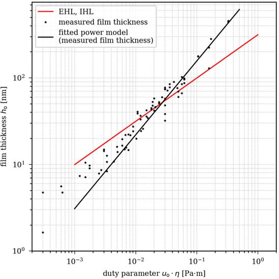
Figure 11.
Empirically measured and calculated oil film thickness at outstroke as a function of the duty parameter ().
It follows that both simulation models cannot predict the oil film thickness precisely over a wide range of speed and viscosity values. The slope and exponent of the power law model representing the simulation results is independent of the model input parameters. Since differences between the simulation models and the empirical data do not depend on the input parameters of the models, we must change or extend the fundamental physical model to achieve more precise results. In this study, the fundamental physical model is based on the Reynolds equation.
4.4. Current Limitations
Theoretical studies indicate that the accuracy of the Reynolds equation must be validated when the reduced Reynolds number is in the order of one or even higher. Results from our film thickness measurements can be used to calculate the reduced Reynolds number in the sealing gap based on empirical data. Assuming that the film thickness in the gap at outstroke is approximately twice the film thickness on the rod, we determined a maximum reduced Reynolds number close to zero. It follows that the assumption of a viscous flow and the validity of the Reynolds equation in the sealing gap are confirmed. However, in the so-called booster zone, the gap height increases significantly—as does the Reynolds number. In this area, lift-generating inertia effects are neglected when the Reynolds equation is used, as was shown in other studies [,,,,]. The loss of accuracy when neglecting inertia effects in the booster-zone cannot yet be quantified and should be the subject of further studies.
In addition, further simplifications were adopted in the presented simulation models. To keep things simple, we simulated two U-cups with differing—but perfectly circular—edged radii. It must be noted that the sealing edge of commercially available U-cups is not perfectly smooth, nor does it have a unique radius, as can be clearly seen in Figure 5. It is conceivable that those imperfections cause discrepancies between simulations and experiments. An advanced approach including the surface roughness was already proposed in [] and applied to radial shaft seals. Huang [] performed simulations with textured rods.
Further differences between experiments and simulations might result from neglecting phenomena such as friction [,], shear thinning [], wall slip and wetting [], viscoelasticity [,] and a conceivable temperature rise in the sealing gap []. Furthermore, even at ambient operating pressure, the pressure in the gap reaches a maximum of approximately 20 MPa. The viscosity–pressure dependence described by Barus [] must not be neglected because an increase of dynamic viscosity in the converging booster zone would additionally intensify the local pressure build-up.
5. Summary and Conclusions
The IHL and EHL are simulation methods that can be utilized to predict the oil film generation and lubrication conditions of rod seals. Both methods require proper validation for specific applications to yield reliable results.
We calculated the oil film thickness of a rod seal after outstroke using both IHL and EHL. Theoretical results were compared with empirical data obtained from film thickness measurements using ellipsometry. Mineral-oil-based lubricants, a commercially available polyurethane U-cup, and a polished rod were used in simulations and experiments.
The calculated film thickness and the measured film thickness are in the same order of magnitude and fall within the range of less than 300 nm. In the IHL and EHL, the film thickness follows a square-root function of the product of speed and viscosity and can be formulated using a power law model with exponent 0.5. This is in contradiction to the measured film thickness using ellipsometry, where an exponent of 0.85 was identified. Through a rigorous parameter study, we showed that the fundamental correlation between film thickness and the duty parameter is not significantly influenced by numerical-model input parameters such as sealing-edge radius, elastic modulus, cavitation model, and grid size. We identified a fundamental difference between both presented simulation models based on the Reynolds equation and the film thickness measurements. This difference does not depend on the actual model input parameters.
Both IHL and EHL can be used to estimate the oil film generation and lubrication conditions of rod seals. However, this study showed that a precise prediction of the film thickness across a wide range of speed and viscosity values is not yet possible. It can be concluded that the presented simulation models based on the Reynolds equation must be extended and improved. In a subsequent step, inertia effects (especially in the booster zone) or the piezo-viscosity of the lubricant at low operating pressures will be included. Furthermore, the exact modeling of the sealing edge—including surface roughness and inhomogeneities—remains a challenging task.
We draw attention to the fact that weaknesses of simulation models for reciprocating seals might only become evident when a wide range of operating conditions is considered. An equally extensive validation is a matter of course. Therefore, we recommend the validation of simulation models for hydraulic rod seals using accurate film thickness measurements (e.g., using ellipsometry or a method with similar precision). To minimize the number of influencing parameters, polished rods and well-defined rod seals are to be preferred as reference. Furthermore, oils of various viscosity classes and various rod speeds will be included for validation over a wide range of operating conditions.
Author Contributions
Conceptualization, O.F. and N.D.; methodology, O.F. and N.D.; investigation, O.F. and N.D.; visualization, O.F.; writing—original draft preparation, O.F.; writing—review and editing, O.F., N.D., L.H., and F.B. All authors have read and agreed to the published version of the manuscript.
Funding
This research received no external funding.
Institutional Review Board Statement
Not applicable.
Informed Consent Statement
Not applicable.
Data Availability Statement
The data of this study are available from the corresponding author (O.F.), upon reasonable request.
Conflicts of Interest
The authors declare no conflict of interest.
Nomenclature
| Mooney–Rivlin material coefficients | |
| Modulus of elasticity | |
| Reduced modulus of elasticity | |
| Static contact force | |
| Film thickness | |
| Film thickness on the rod after outstroke | |
| Film thickness at the maximum pressure at outstroke | |
| Minimal film thickness | |
| Film thickness at the maximum pressure gradient at outstroke | |
| Static contact geometry | |
| Length | |
| Hydrodynamic pressure | |
| Static contact pressure | |
| Reynolds number | |
| Reduced Reynolds number | |
| Rod speed | |
| Maximum pressure gradient | |
| Cartesian coordinate | |
| Dynamic viscosity | |
| Poisson’s ratio | |
| Density |
References
- Müller, H.K.; Nau, B.S. Fluid Sealing Technology: Principles and Applications; Marcel Dekker: New York, NY, USA, 1998; ISBN 0-8247-9969-0. [Google Scholar]
- Flitney, R. Reciprocating Seals. In Seals and Sealing Handbook; Butterworth-Heinemann: Oxford, UK, 2014; pp. 289–367. ISBN 978-0-08-099416-1. [Google Scholar]
- Bauer, F. Tribologie-Prägnant und Praxisrelevant; Springer: Wiesbaden, Germany, 2021; ISBN 978-3-658-32920-4. [Google Scholar]
- Yoshimura, K.; Suzuki, N.; Mizuta, H. Oil film formation of reciprocating seals observed by interferometry. Tribol. Online 2014, 9, 106–112. [Google Scholar] [CrossRef][Green Version]
- Feuchtmüller, O.; Hörl, L.; Bauer, F. Oil film generation of a hydraulic rod seal: An experimental study using ellipsometry. Tribol. Int. 2021, 162, 107102. [Google Scholar] [CrossRef]
- Kaneta, M.; Todoroki, H.; Nishikawa, H.; Kanzaki, Y.; Kawahara, Y. Tribology of Flexible Seals for Reciprocating Motion. J. Tribol. 2000, 122, 787–795. [Google Scholar] [CrossRef]
- Hörl, L.; Haas, W.; Nißler, U. A comparison of test methods for hydraulic rod seals. Seal. Technol. 2009, 2009, 8–13. [Google Scholar] [CrossRef]
- El Gadari, M.; Hajjam, M. Effect of the Grooved Rod on the Friction Force of U-Cup Hydraulic Rod Seal with Rough Lip. Tribol. Trans. 2018, 61, 661–670. [Google Scholar] [CrossRef]
- Huang, P. Numerical Calculation of Elastohydrodynamic Lubrication; Wiley-VCH: Singapore, 2015; ISBN 978-1-118-92096-1. [Google Scholar]
- Stupkiewicz, S.; Marciniszyn, A. Elastohydrodynamic lubrication and finite configuration changes in reciprocating elastomeric seals. Tribol. Int. 2009, 42, 615–627. [Google Scholar] [CrossRef]
- Wang, J.; Li, Y.; Lian, Z. Numerical investigations on the sealing performance of a reciprocating seal based on the inverse lubrication method. J. Tribol. 2019, 141, 1–9. [Google Scholar] [CrossRef]
- Kaiser, F. Ein Simulationsmodell zur Analyse des Schmierfilms von Stangendichtungen. Ph.D. Thesis, University of Kaiserslautern, Kaiserslautern Germany, 2015. [Google Scholar]
- Crudu, M.; Fatu, A.; Cananau, S.; Hajjam, M.; Pascu, A.; Cristescu, C. A numerical and experimental friction analysis of reciprocating hydraulic “U” rod seals. Proc. Inst. Mech. Eng. Part J J. Eng. Tribol. 2012, 226, 785–794. [Google Scholar] [CrossRef]
- Fatu, A.; Hajjam, M. Numerical modelling of hydraulic seals by inverse lubrication theory. Proc. Inst. Mech. Eng. Part J J. Eng. Tribol. 2011, 225, 1159–1173. [Google Scholar] [CrossRef]
- Blok, H. Inverse problems in hydrodynamic lubrication and design directives for lubricated flexible surfaces. In Proceedings of the International Symposium on Lubrication and Wear, Houston, TX, USA, 1963; Available online: https://www.semanticscholar.org/paper/Inverse-problem-in-hydrodynamic-lubrication-and-for-Blok/cea3fb427343dba5d44527bc8580d0714cfbc2fd#citing-papers (accessed on 10 September 2021).
- Szeri, A.Z. Effects of Fluid Inertia. In Fluid Filmd Lubrication; Cambridge University Press: Cambridge, UK, 2011; pp. 184–221. ISBN 9780521898232. [Google Scholar]
- Dobrica, M.B.; Fillon, M. About the validity of Reynolds equation and inertia effects in textured sliders of infinite width. Proc. Inst. Mech. Eng. Part J J. Eng. Tribol. 2009, 223, 69–78. [Google Scholar] [CrossRef]
- Brunetière, N.; Tournerie, B. The Effect of Inertia on Radial Flows—Application to Hydrostatic Seals. J. Tribol. 2006, 128, 566–574. [Google Scholar] [CrossRef]
- Nikas, G.K. Eighty years of research on hydraulic reciprocating seals: Review of tribological studies and related topics since the 1930s. Proc. Inst. Mech. Eng. Part J J. Eng. Tribol. 2010, 224, 1–23. [Google Scholar] [CrossRef]
- Nau, B.S. An historical review of studies of polymeric seals in reciprocating hydraulic systems. Proc. Inst. Mech. Eng. Part J J. Eng. Tribol. 1999, 213, 215–226. [Google Scholar] [CrossRef]
- Visscher, M.; Kanters, A.F.C. Literature review and discussion on measurements of leakage, lubricant film thickness and friction of reciprocating elastomeric seals. Lubr. Eng. 1990, 46, 785–791. [Google Scholar]
- Freudenberg Sealing Technology GmbH & Co. KG: E-Catalog of Freudenberg Sealing Technologies. Available online: https://ecatalog.fst.com/ (accessed on 13 September 2021).
- Tompkins, H.G. A User’s Guide to Ellipsometry; Academic Press: San Diego, CA, USA, 1993. [Google Scholar]
- Vijayaraghavan, D.; Keith, T.G. Development and Evaluation of a Cavitation Algorithm. Tribol. Trans. 1989, 32, 225–233. [Google Scholar] [CrossRef]
- Dakov, N. Elastohydrodynamische Simulation von Wellendichtungen am Beispiel der PTFE-Manschettendichtung mit Rückförderstrukturen (Elastohydrodynamic Lubrication Analysis of Shaft Seals on the Example of the PTFE Lip Seal with Sealing Aids). Ph.D. Thesis, University of Stuttgart, Stuttgart, Germany, 2020. [Google Scholar]
- Johnson, K.L. Contact Mechanics; Cambridge University Press: Cambridge, UK, 1987. [Google Scholar]
- Sainsot, P.; Lubrecht, A.A. Efficient solution of the dry contact of rough surfaces: A comparison of fast Fourier transform and multigrid methods. Proc. Inst. Mech. Eng. Part J J. Eng. Tribol. 2011, 225, 441–448. [Google Scholar]
- Liu, S.; Wang, Q.; Liu, G. A versatile method of discrete convolution and FFT (DC-FFT) for contact analyses. Wear 2000, 243, 101–111. [Google Scholar] [CrossRef]
- Hamrock, B.J.; Dowson, D. Isothermal Elastohydrodynamic Lubrication of Point Contacts: Part 1—Theoretical Formulation. J. Lubr. Technol. 1976, 98, 223–228. [Google Scholar] [CrossRef]
- Heipl, O.; Murrenhoff, H. Simulation of Reciprocating Seals. In Encyclopedia of Lubricants and Lubrication; Mang, T., Ed.; Springer: Berlin/Heidelberg, Germany, 2014; pp. 1803–1816. ISBN 978-3-642-22647-2. [Google Scholar]
- Nikas, G.K.; Sayles, R.S. Study of leakage and friction of flexible seals for steady motion via a numerical approximation method. Tribol. Int. 2006, 39, 921–936. [Google Scholar] [CrossRef]
- Kanters, A.F.C.; Verest, J.F.M.; Visscher, M. On Reciprocating Elastomeric Seals: Calculation of Film Thicknesses Using the Inverse Hydrodynamic Lubrication Theory. Tribol. Trans. 1990, 33, 301–306. [Google Scholar] [CrossRef]
- Bullock, A.K.; Tilley, D.G.; Johnston, D.N.; Bowen, C.R.; Keogh, P.S. Non-linear friction in reciprocating hydraulic rod seals: Simulation and measurement. J. Phys. Conf. Ser. 2009, 181, 12009. [Google Scholar] [CrossRef]
- Constantinescu, V.N.; Galetuse, S. On the Possibilities of Improving the Accuracy of the Evaluation of Inertia Forces in Laminar and Turbulent Films. J. Lubr. Technol. 1974, 96, 69–77. [Google Scholar] [CrossRef]
- Rom, M.; Müller, S. A new model for textured surface lubrication based on a modified Reynolds equation including inertia effects. Tribol. Int. 2019, 133, 55–66. [Google Scholar] [CrossRef]
- Dousti, S.; Cao, J.; Younan, A.; Allaire, P.; Dimond, T. Temporal and Convective Inertia Effects in Plain Journal Bearings With Eccentricity, Velocity and Acceleration. J. Tribol. 2012, 134, 031704. [Google Scholar] [CrossRef]
- Dousti, S.; Fittro, R.L. An Extended Reynolds Equation Including the Lubricant Inertia Effects: Application to Finite Length Water Lubricated Bearings. In Proceedings of the ASME Turbo Expo 2015: Turbine Technical Conference and Exposition, Montreal, QC, Canada, 15–19 June 2015. [Google Scholar]
- Grün, J.; Feldmeth, S.; Bauer, F. Wear on radial lip seals: A numerical study of the influence on the sealing mechanism. Wear 2021, 476, 203674. [Google Scholar] [CrossRef]
- Wang, B.; Peng, X.; Meng, X. Simulation of the effects of non-Newtonian fluid on the behavior of a step hydraulic rod seal based on a power law fluid model. J. Zhejiang Univ. A 2018, 19, 824–842. [Google Scholar] [CrossRef]
- Schuler, P.; Haas, W. The wettability of sealing materials and its effect on sealing performance: Part II. Seal. Technol. 2016, 2016, 7–11. [Google Scholar] [CrossRef]
- Thatte, A.; Salant, R.F. Visco-elastohydrodynamic model of a hydraulic rod seal during transient operation. J. Tribol. 2010, 132. [Google Scholar] [CrossRef]
- Schmidt, T.; André, M.; Poll, G. A transient 2D-finite-element approach for the simulation of mixed lubrication effects of reciprocating hydraulic rod seals. Tribol. Int. 2010, 43, 1775–1785. [Google Scholar] [CrossRef]
- Wang, B.; Peng, X.; Meng, X. A thermo-elastohydrodynamic lubrication model for hydraulic rod O-ring seals under mixed lubrication conditions. Tribol. Int. 2019, 129, 442–458. [Google Scholar] [CrossRef]
- Barus, C. Isothermals, isopiestics and isometrics relative to viscosity. Am. J. Sci. 1893, 45, 87–96. [Google Scholar] [CrossRef]
Publisher’s Note: MDPI stays neutral with regard to jurisdictional claims in published maps and institutional affiliations. |
© 2021 by the authors. Licensee MDPI, Basel, Switzerland. This article is an open access article distributed under the terms and conditions of the Creative Commons Attribution (CC BY) license (https://creativecommons.org/licenses/by/4.0/).