1. Introduction
Cavitation is a complex phenomenon that usually occurs in the region where the liquid pressure is below cavitation pressure [
1,
2]. When it occurs, gas will escape (or vaporize) from the liquid, forms bubbles, and occupy part of the space. The bubbles result in a change of pressure and make the bearing behave differently. Generally, cavitation is divided into air cavitation and vapor cavitation [
3]. Air cavitation is air dissolved in oil escaping from the solution. It occurs when the pressure is below saturation pressure. Vapor cavitation is due to the pressure being lower than the saturated vapor pressure, where the oil boils to form bubbles [
4]. No matter what kind of cavitation, they represent the rupture and reformation of the oil film. In full circle journal bearings with stationary load, cavitation takes place in the section of divergent clearance region. The oil film is separated by finger-shaped voids (cavities), and the shape of the cavitated region remains relatively stable.
Two methods, namely the Reynolds model [
5] and the Jakobsson–Floberg–Olsson (JFO) theory [
6,
7], are commonly used to evaluate the bearing performance. The well-known Reynolds boundary condition belongs to the Reynolds model. It requires the pressure derivative smoothly approaching zero to locate the oil film rupture boundary. The oil film reformation boundary is not explained in the Reynolds boundary condition. However, in the numerical solution of the Reynolds equation, an algorithm that sets the negative pressure to zero, developed by Christopherson [
8], provided an opportunity to locate the oil film reformation boundary. A complete shape of the cavitated region can be obtained by choosing a cavitation pressure lower than 0 Pa (ambient pressure). The oil film reformation boundary is curious because it is an additional product within Christopherson’s method. The effect of the oil film reformation boundary on the Reynolds model’s accuracy is unclear. In practical calculations, the cavitation pressures of 0 Pa and lower than 0 Pa are both applied [
9,
10,
11,
12]. The Reynolds model with a cavitation pressure lower than 0 Pa has not been fully studied.
The JFO theory is an improvement to the Reynolds model due to density term being preserved in the mass continuity equation. It incorporates the Reynolds boundary condition and provides the oil film reformation boundary condition. A detailed explanation of the oil film reformation boundary condition can be seen in [
6,
7]. The JFO theory is well accepted because it obeys the law of conservation of mass, and had been validated by experiments [
6,
7]. A variety of algorithms [
10,
13,
14,
15,
16,
17] have been developed for implementing the JFO theory, such as the well-known Elrod algorithm [
13]. Although the complexity of the algorithm is higher than the Christopherson’s method, it was largely used in studying cavitation and its effect on bearing characteristics [
18,
19].
The effects of cavitation on the journal bearing characteristics are mainly reflected in load capacity, friction force, leakage, etc. The effect of load capacity is generally considered not to be significant, because cavitation always occurs out of the positive pressure region [
20]. The friction force is significantly affected by the cavitation, as almost half of the region is dominated by the cavitation, where the friction characteristic is changed by the separation of oil and gas [
10]. The accuracy of the predicted leakage depends on the location of the oil film reformation boundary. It is a primary sign reflecting the difference between the Reynolds model and the JFO theory.
Moreover, cavitation plays a key role in surface textured bearings [
1,
21]. The bearing performance is altered by adding surface texture (such as dimples). Cavitation will occur in local divergent gaps and thus alters the established hydrodynamic pressure. A lot of research has been devoted to this area [
22,
23,
24,
25,
26,
27,
28]. Promising results have been obtained [
21,
29,
30,
31,
32], although a consistent conclusion has not been reached. Cavitation behavior is complex in surface textures due to the variation of cavitation pressure, rotational speed, pattern/distribution of textures, etc. The adoption of a mass-conserving model has been widely recognized for analyzing surface textured bearings [
10].
Although the effect of cavitation has been investigated for ordinary journal bearings [
1,
2,
3,
4], the presentation of results is still insufficient. The evaluation of the difference between a non-mass-conserving model and a mass-conserving model is not clear. In this paper, a comprehensive analysis was conducted to study the effects of cavitation on the performance of steadily loaded journal bearings. The Christopherson’s method and Elrod cavitation algorithm were implemented to represent the Reynolds model and the JFO theory, respectively. The two methods were compared under different cavitation pressures. The typical performance parameters including oil film pressure, load-carrying capacity, attitude angle, friction force, and leakage were analyzed. The aim of the paper is twofold: (1) The effect of cavitation on bearing characteristics is presented. The results are beneficial for the understanding of lightly loaded cavitated bearings due to the amplified cavitation effect. (2) The comparison of the Reynolds model and the JFO theory was investigated. The purpose was to analyze the necessity of adopting a mass-conserving model for ordinary journal bearings. The accuracy of the Reynolds model was analyzed by focusing on the location of the inaccurate oil film reformation boundary. It helps to understand the non-mass-conserving Reynolds model.
3. Bearing Condition and Parameters
The incompressible Reynolds equation is linear. When cavitation is considered, the preserved density term makes the Reynolds equation be nonlinear [
36]. Hence, bearing number Λ is introduced to help analysis, as expressed by
where
ω is the angular velocity,
pa is the ambient pressure,
R is the journal radius, and
C is the radius clearance.
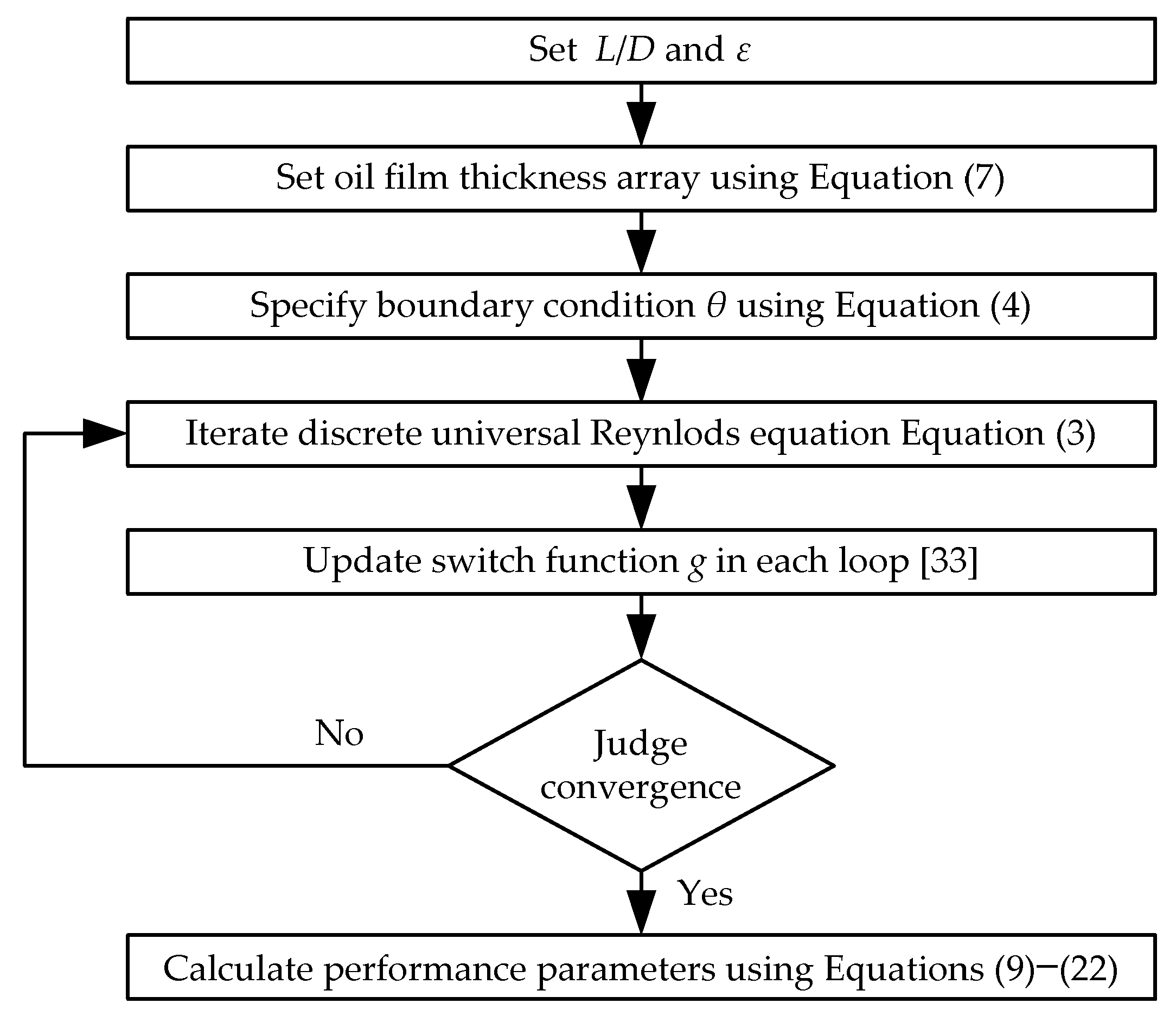
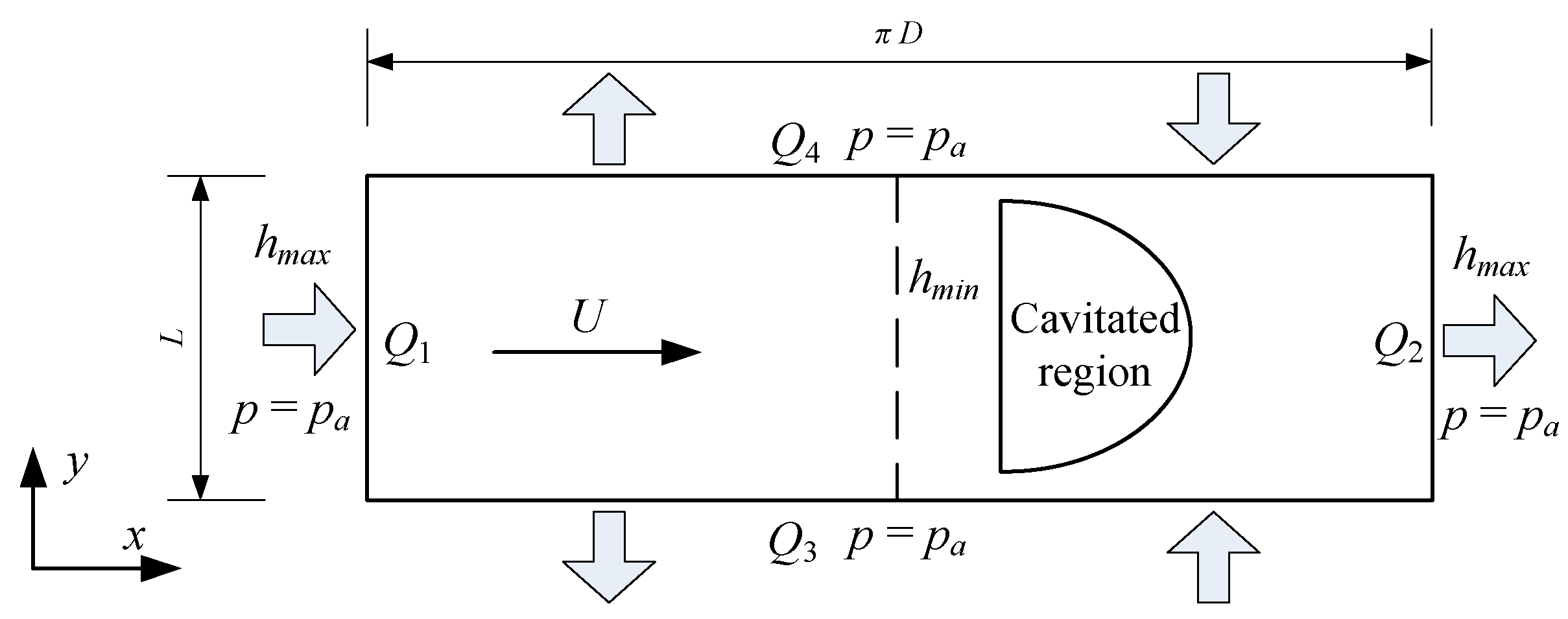
A typical plain journal bearing was analyzed to present the effect of cavitation on the bearing characteristics and the difference to the Reynolds model. For the sake of simplicity, the bearing is considered unwrapped by ignoring the curvature, allowing for the use of Cartesian coordinate system. Consider a rectangle geometry that represents the bearing clearance region, as shown in
Figure 3. Assuming the hydrodynamic film begins at
hmax, the film thickness profile is expressed by
where
ε is the eccentricity ratio and
ϕ is the angle coordinate starting from
hmax. Due to the use of the Cartesian coordinate system, the relation between
ϕ and
x is
where
x = 0,
ϕ = 0 is at the maximum film thickness, and
x =
πR,
ϕ =
π is at the minimum film thickness.
Various methods are available for distributing lubricant for a journal bearing. Although different oil supply methods impact on the bearing characteristics differently, only a typical oil supply is considered here. The oil supply is kept along the axial clearance of
hmax. In practical bearings, the position of
hmax depends on the attitude angle that varies with load. The precise oil supply location is hard to maintain. However, this oil supply method was largely applied in theoretical analysis [
3,
36,
37] because it presents the characteristics of a plane oil film. There are four boundaries around the bearing geometry. All of them are treated as the pressure boundary condition with
pa = 0 Pa. The bearing is considered as a submerged bearing.
The bearing performance parameters including oil film pressure
p, load-carrying capacity
W, attitude angle
ψ, friction force
F, and leakage
q were analyzed below. For comparison purposes, all the performance parameters are taken as dimensionless forms. These performance parameters are calculated as follows. The dimensionless pressure
is defined by
where
Ns is the rotational speed in rev/s. The radial and tangential loads,
Wr and
Wt, are, respectively calculated by
where
D is the bearing diameter and
L is the bearing length. The differential of d
ϕ satisfies
Rd
ϕ = d
x. The attitude angle
ψ is expressed by
The total load
W is calculated by
The dimensionless load
is defined by
where
S is the Sommerfeld number. The Sommerfeld number is written as
The friction coefficient (
R/
C)
f is calculated by
The friction coefficient calculated by Equation (15) is used to predict both the liquid and cavitated region, although it needs be more discussed due to the complex liquid–air separation. The dimensionless leakage
is given by
Equations (16)–(19) are valid under the condition of full film boundary conditions (θ ≥ 1, submerged bearing).
4. Cavitation Analysis
Cavitation pressure is usually between ambient pressure and absolute zero pressure. Traditional bearing analysis often adopted 0 Pa as the cavitation pressure. This assumption is particularly suitable for the Reynolds model because oil film reformation cannot arise under the condition of cavitation pressure equaling oil supply pressure. Many works, as represented by Khonsari and Booser [
3], have summarized the numerical solutions of plain journal bearings based on this assumption. In the JFO theory, the cavitation pressure can be taken as negative pressure, which is closer to the actual situation. The actual cavitation pressure varies with different bearings and operation conditions [
4]. In the below analysis, the cavitation pressures of 0 Pa, −0.5 × 10
5 Pa and −1.0 × 10
5 Pa were analyzed for the two methods.
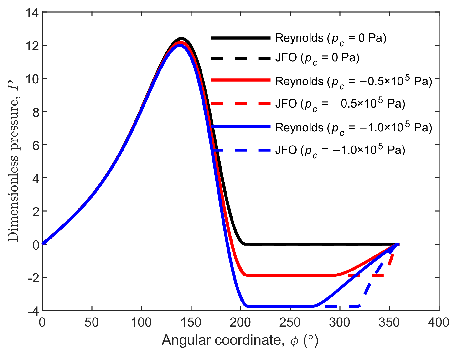
Figure 4 shows the central pressure variation with different
pc for the Reynolds model and the JFO theory. The pressure obtained using the Reynolds model is the same to that obtained using the JFO theory at the condition of cavitation pressure equaling ambient pressure (the black dotted line is covered by the black solid line). If the cavitation pressure is lower than the ambient pressure, the two methods provide different results. The oil film rupture boundary predicted using the Reynolds model is the same to that predicted using the JFO theory, but the oil film reformation boundary predicted using the Reynolds model is ahead of that predicted using the JFO theory. It implies that, the cavitated area is underestimated using the Reynolds model, and the difference between the two methods increases with the reducing cavitation pressure.
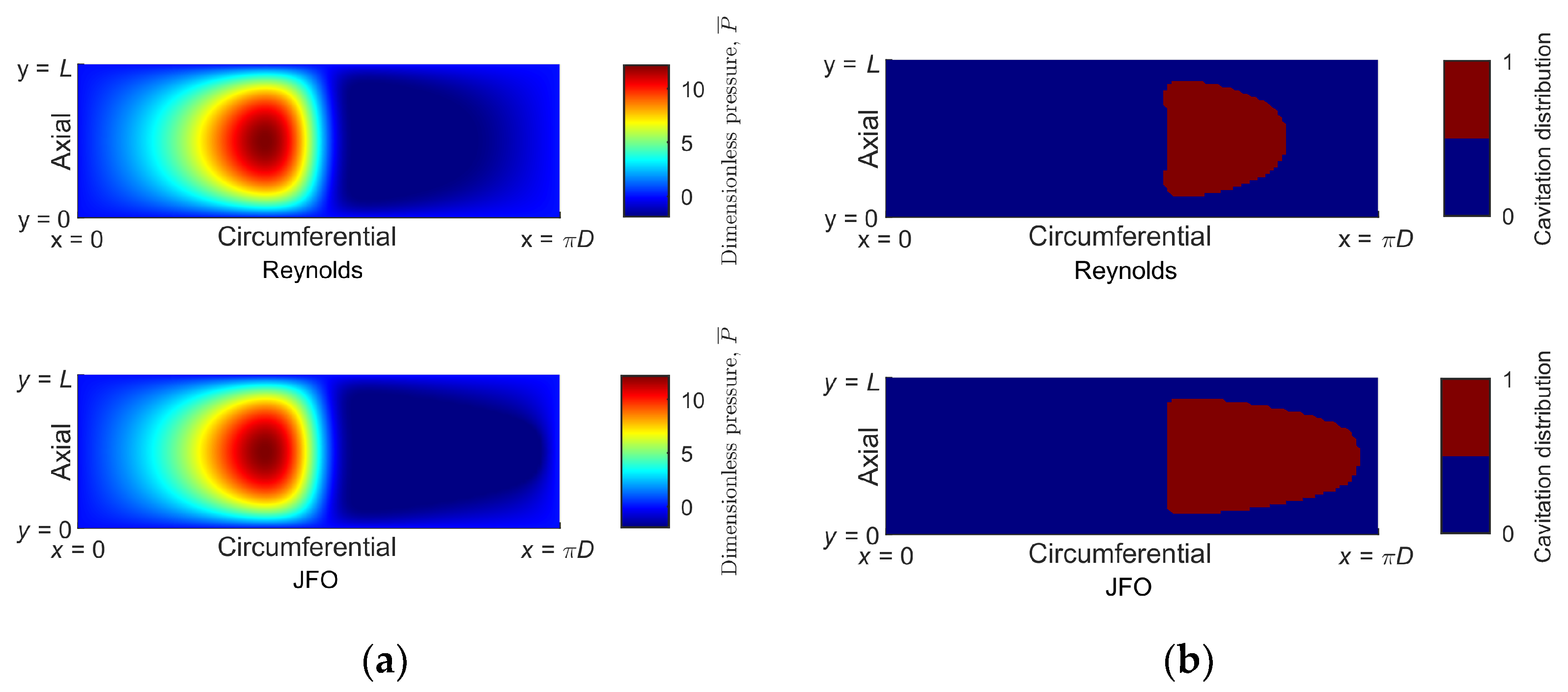
To further explain the difference,
Figure 5a compares the pressure contours at
pc = −0.5 × 10
5 Pa for the Reynolds model and the JFO theory. The pressure distribution in the liquid region is basically the same for the two methods, while the pressure distribution in the cavitated region is obviously different. The difference is mainly reflected by the different shapes of cavitated areas, as shown in
Figure 5b. The cavitation patterns predicted using the two methods look like half ellipses. The major axis of the ellipse predicted using the Reynolds model is shorter than that predicted using the JFO theory. This difference is due to the fact that the density effect in the cavitated region is not reflected in the Reynolds model. In other words, mass conservation is not always satisfied with the Reynolds model. The quantitative effect of cavitation pressure on the bearing characteristics is presented below.
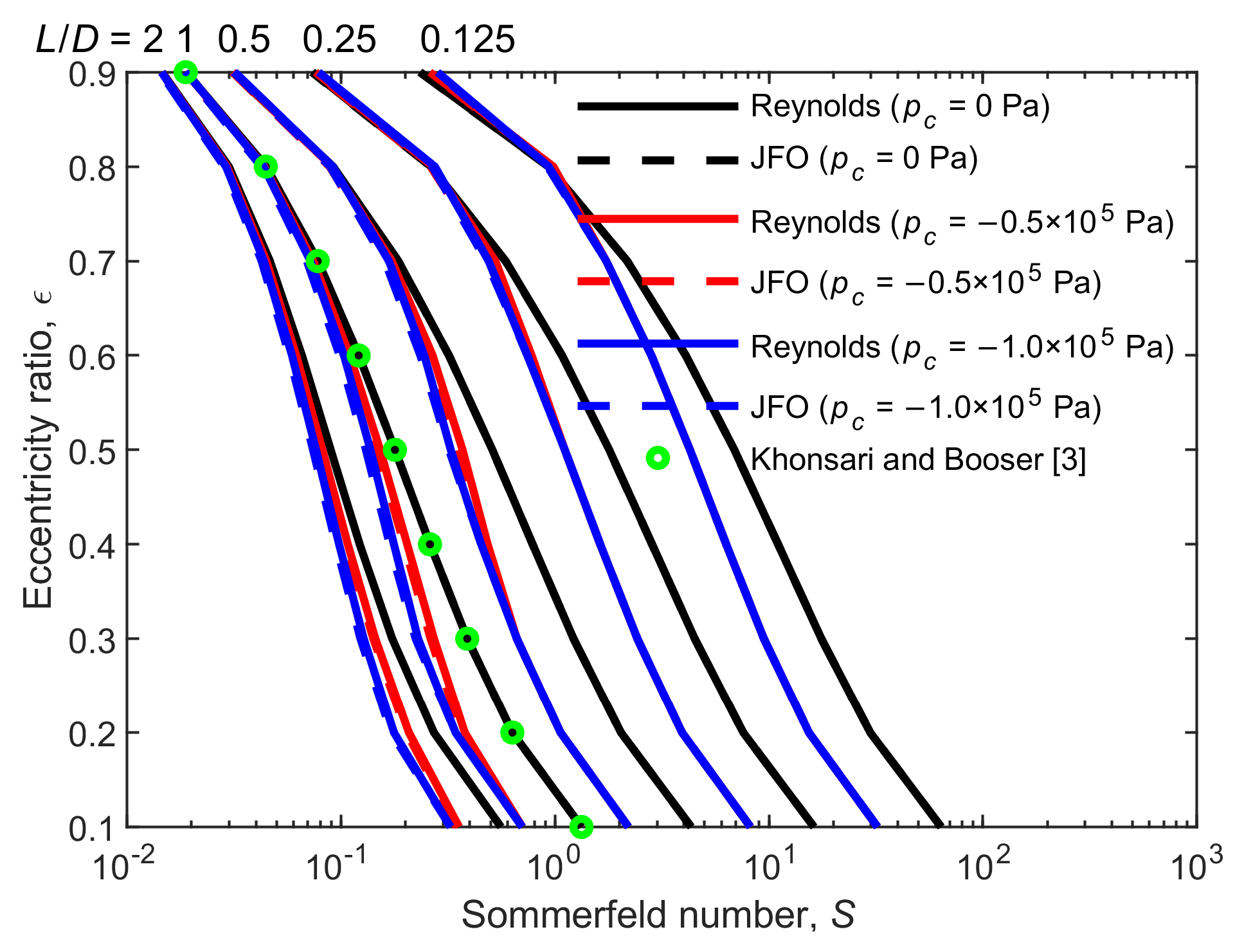
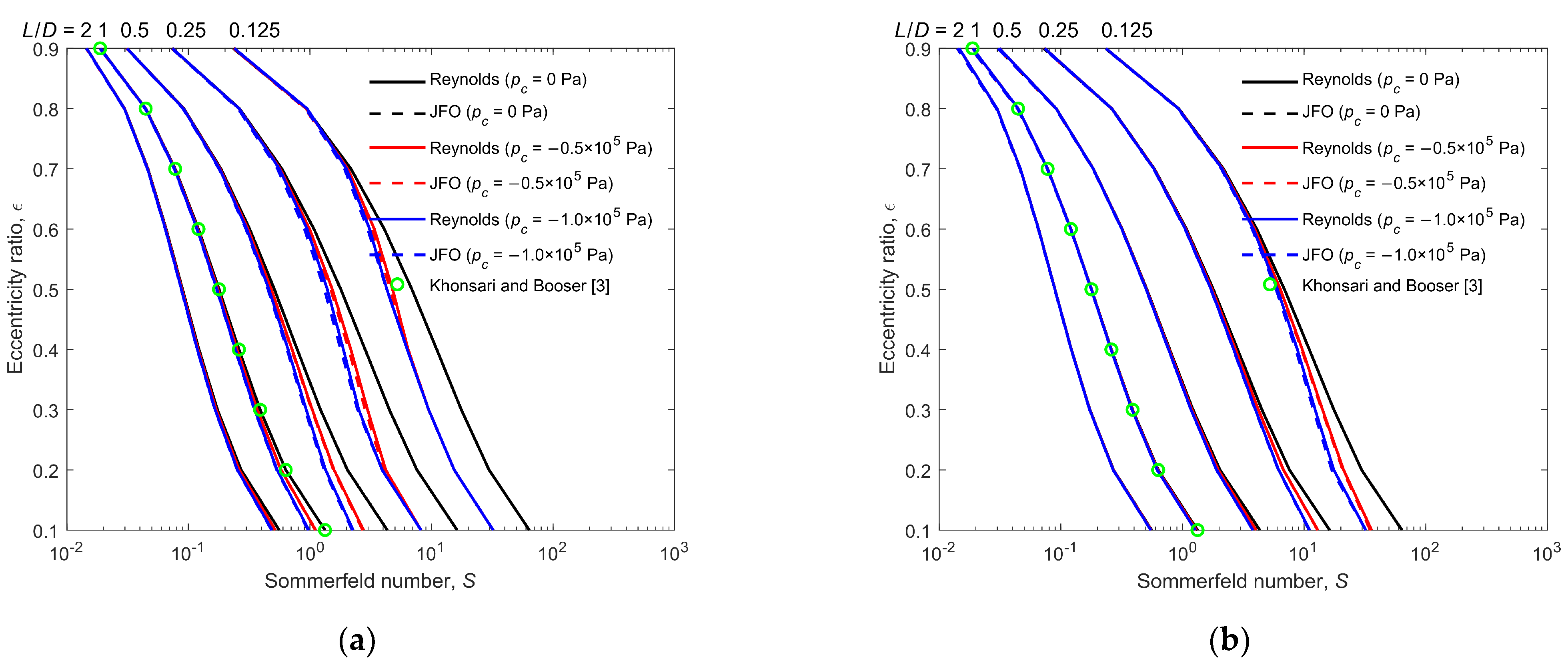
Figure 6 shows the effect of cavitation pressure on the Sommerfeld number for the Reynolds model and the JFO theory. The effects of the length to diameter ratio
L/
D, and eccentricity ratio
ε are also presented. The Sommerfeld number
S is an important parameter used to predict bearing characteristics. It represents the reciprocal load-carrying capacity, as related by
. First of all, let us focus on the bearing with
pc = 0 Pa, as represented by the black lines. The resulting Sommerfeld number agrees well with the result provided by Khonsari and Booser [
3] under different
L/
D and
ε. Moreover, the Sommerfeld number predicted using the JFO theory is the same as that predicted using the Reynolds model (the black dotted lines are covered by the black solid lines), since there is no film reformation. Secondly, let us observe the blue lines that represent the bearings with
pc = −1.0 × 10
5 Pa. (1) The Sommerfeld number of the bearing with
pc = −1.0 × 10
5 Pa is smaller than that of the bearing with
pc = 0 Pa for most cases. It implies that the load-carrying capacity is enhanced by the reducing cavitation pressure, which is in accordance with the comment on cavitation by Dowson and Taylor [
20]. (2) The difference in the Sommerfeld number between the different cavitation pressures gradually decreases with the increasing
ε and
L/
D. This can be explained by the extent of the hydrodynamic effect. With the increase in
ε and
L/
D, the convergence clearance becomes narrower, and more oil is kept in the clearance; hence, the hydrodynamic effect is enhanced. The positive pressure in the convergence clearance region is increased, while the negative pressure in the cavitated region is kept in the constant cavitation pressure. This behavior weakens the cavitation effect on the load-carrying capacity. (3) The Sommerfeld number predicted using the JFO theory is basically the same to that predicted using the Reynolds model for most cases. The slight difference appears in the condition of medium
ε and large
L/
D, where the Sommerfeld number predicted using the JFO theory is slightly smaller than that predicted using the Reynolds model. It implies that the Reynolds model underestimates the load-carrying capacity. This is contrarily compared to the case of microtextured thrust bearings, in which the load-carrying capacity is overestimated using the Reynolds model. In journal bearings, the cavitated area can increase the load because the integral calculation is along the circular surface and the cavitated region is on the opposite side of the positive pressure region. Finally, the bearing with
pc = −0.5 × 10
5 Pa is presented by the red lines. The variation behavior of the Sommerfeld number is between the two situations mentioned above.
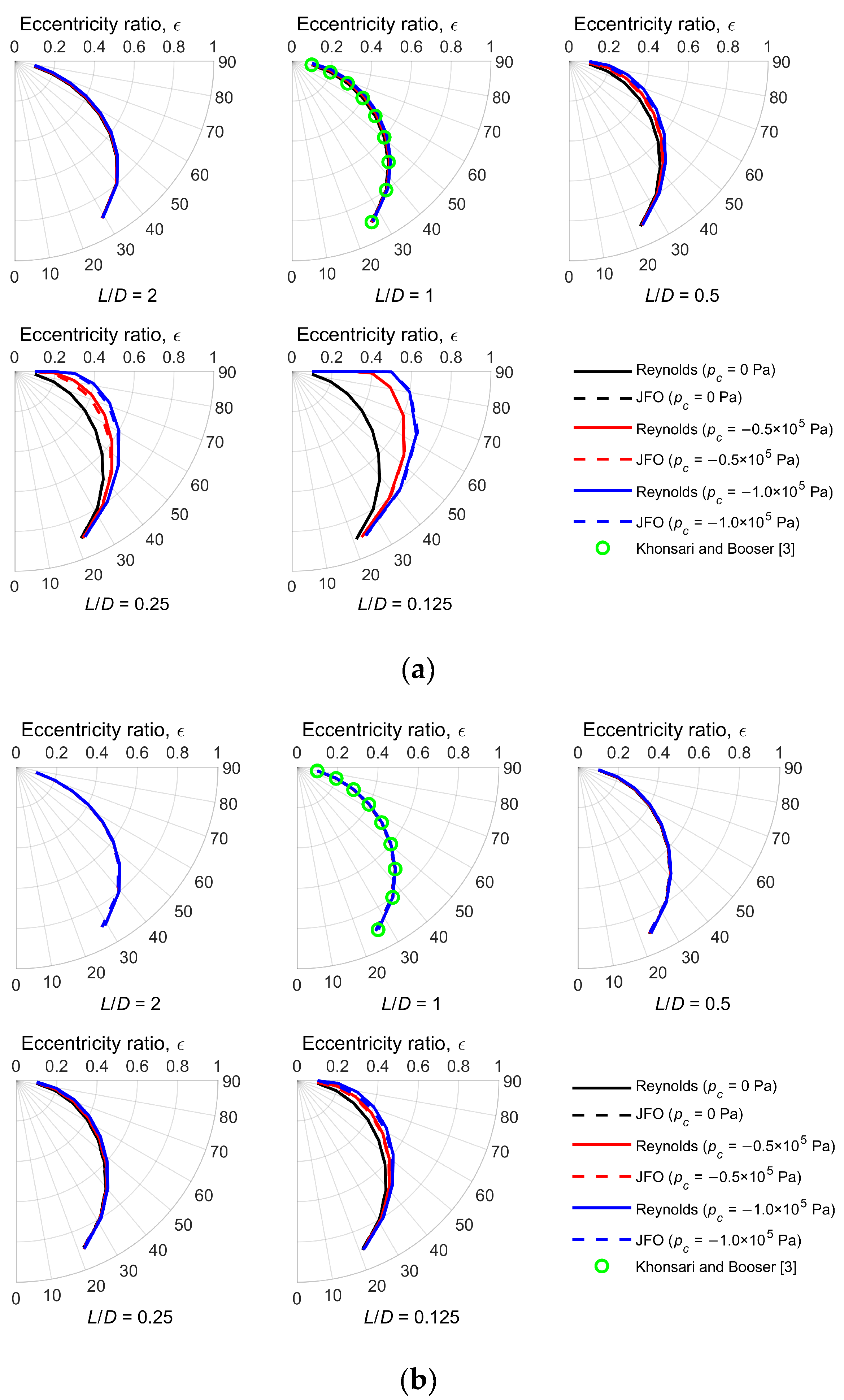
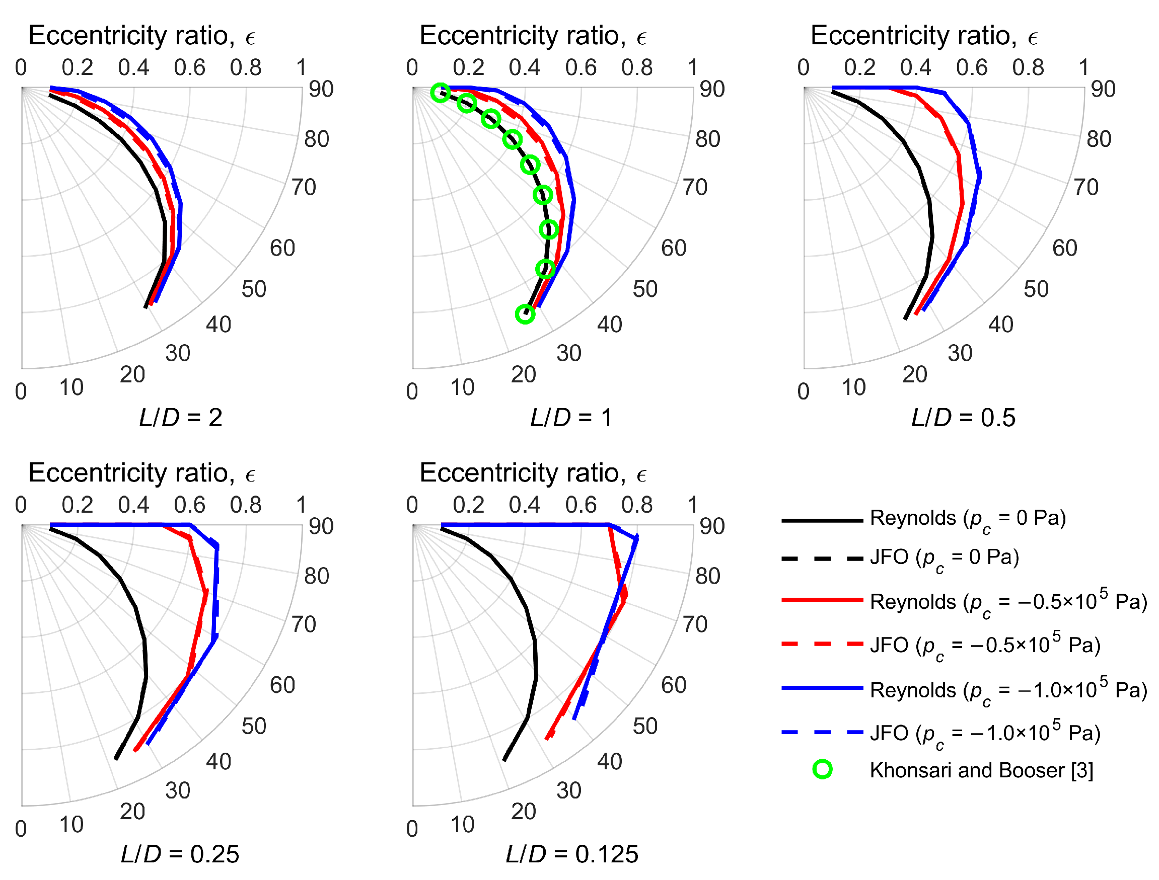
Figure 7 shows the effect of cavitation pressure on the attitude angle for the Reynolds model and the JFO theory. On the one hand, the resulting attitude angles predicted by the two methods are the same at the condition of
pc = 0 Pa for different
L/
D and
ε (the black dotted lines are covered by the black solid lines), and agree well with the results provided by Khonsari and Booser [
3]. On the other hand, (1) the effect of cavitation pressure on the attitude angle is larger than that on the Sommerfeld number. The attitude angle increases with the reducing cavitation pressure. This is due to the increase in the load-carrying capacity, making the bearing self-adjust to a large attitude angle to reduce the load. Moreover, the difference in the attitude angle between different cavitation pressures increases with the decrease in
L/
D. In extreme cases, the attitude angle reaches the maximum of 90°, which appears at the bearing with a small
L/
D and
ε. In fact, the attitude angle of 90° is the full Sommerfeld solution. This is due to the weak hydrodynamic effect that cannot make cavitation occur. In other words, the negative pressure peak is higher than the predetermined cavitation pressure. (2) The attitude angle predicted using the Reynolds model is basically the same to that predicted using the JFO theory. This difference is not obvious.
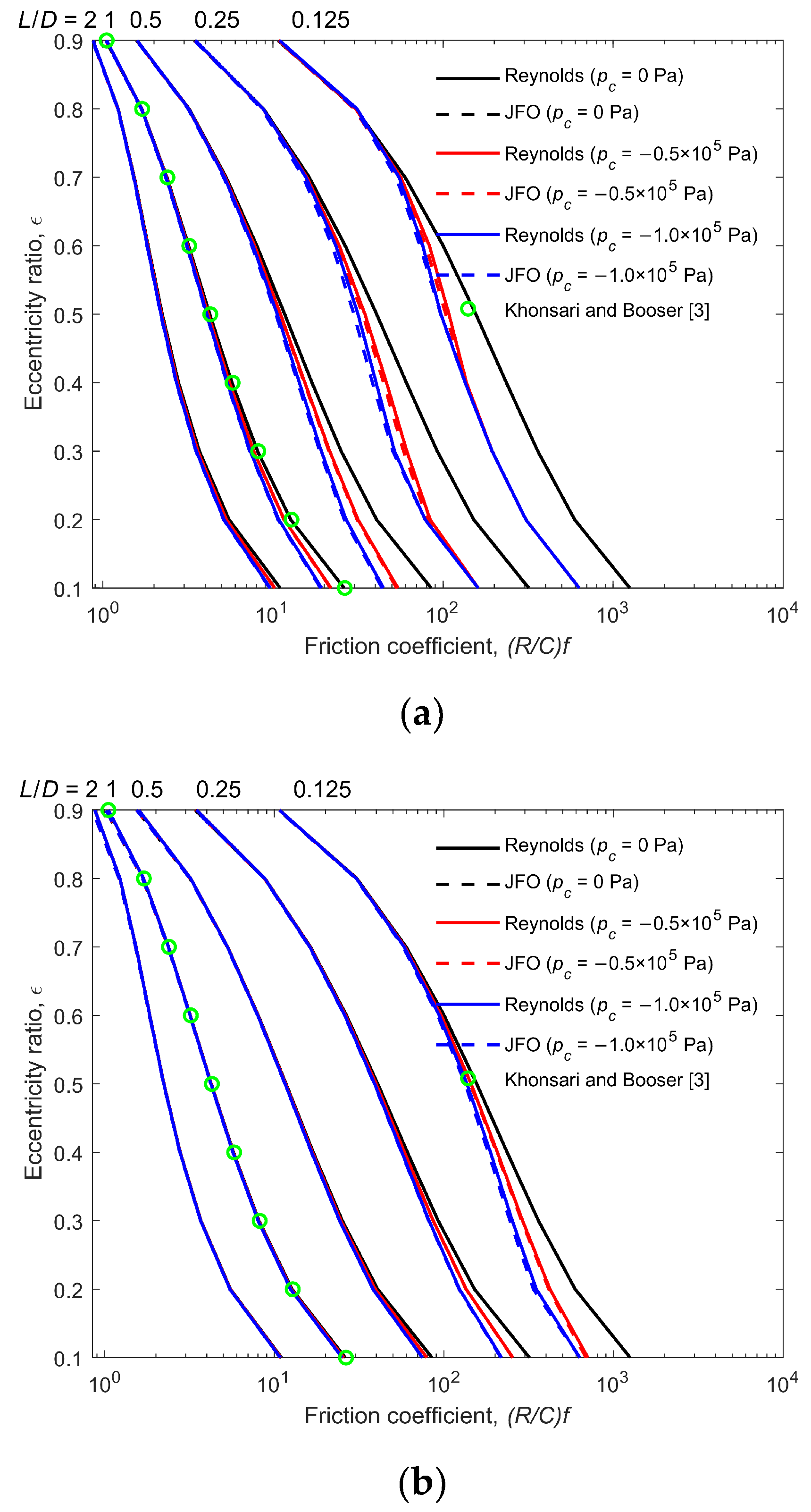
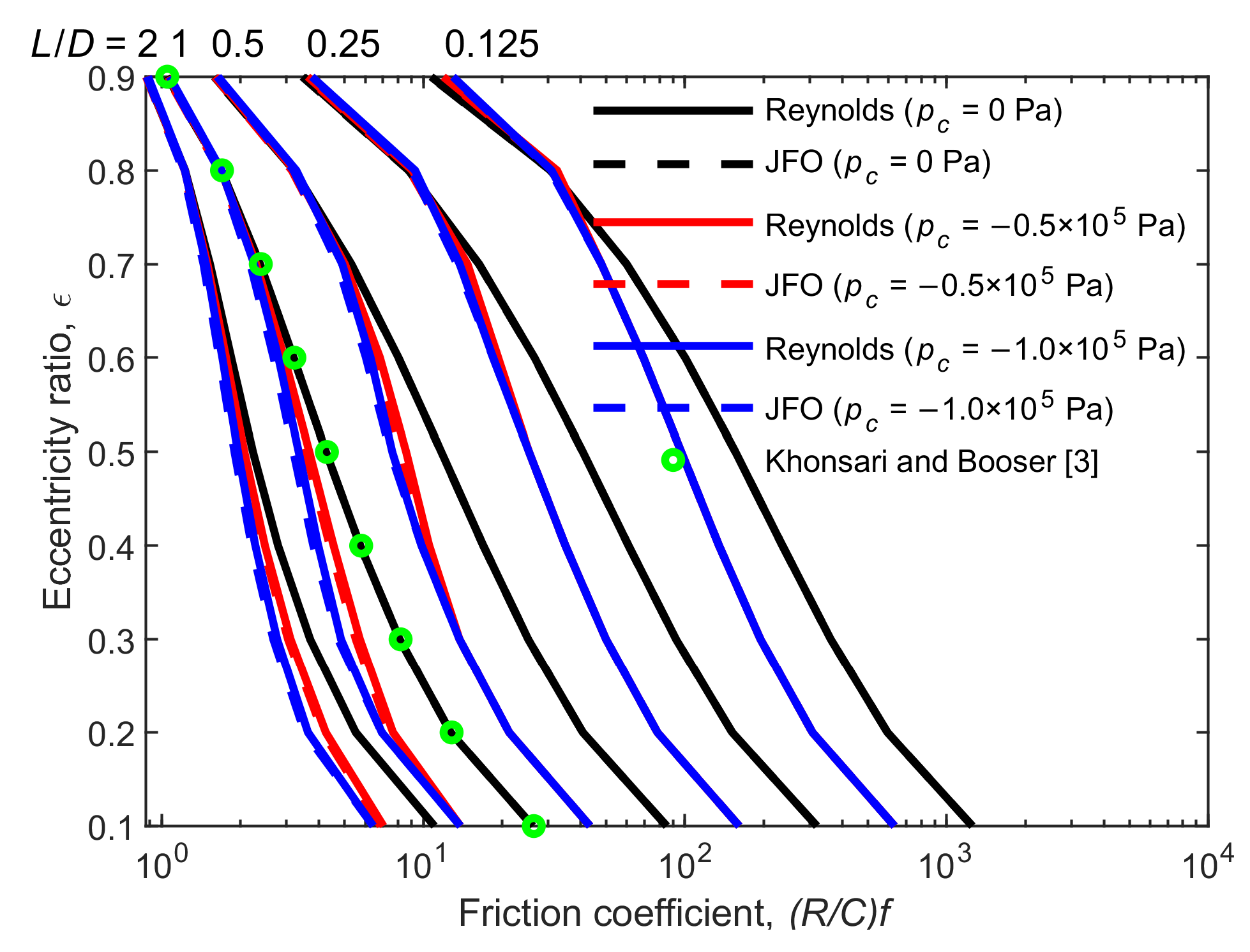
Figure 8 shows the effect of cavitation pressure on the friction coefficient for the Reynolds model and the JFO theory. The friction coefficient (
R/
C)
f represents the ratio of friction force
f to load capacity
W. The variation of the friction coefficient is very similar to that of the Sommerfeld number. This is due to the characteristic of Petroff’s formula, which indicates the relation between torque and power loss in a journal bearing [
3]. In concentric bearing with zero eccentricity, the Petroff’s formula reveals that the friction coefficient and the Sommerfeld number are related by
where 2
π2 indicates the Petroff multiplier [
37]. The Petroff multiplier increases with the increasing eccentricity ratio. Hence, as the eccentricity ratio increases, the rate of decrease in the friction coefficient is slightly slower than that of the Sommerfeld number. Similar to the variation of the Sommerfeld number, the same behavior for the friction coefficient is obtained as (1) the friction coefficient decreases with the decreasing cavitation pressure for most cases; (2) the difference in the friction coefficient between different cavitation pressures gradually decreases with the increasing
ε and
L/
D, since the hydrodynamic effect enhances; and (3) the friction coefficient is overestimated by the Reynolds model but the difference is small. In addition, the resulting friction coefficient is calculated by Equation (15), where the effect of
θ on the friction coefficient is not considered. The viscous shear stress variation due to the cavitation effect needs to be further investigated.
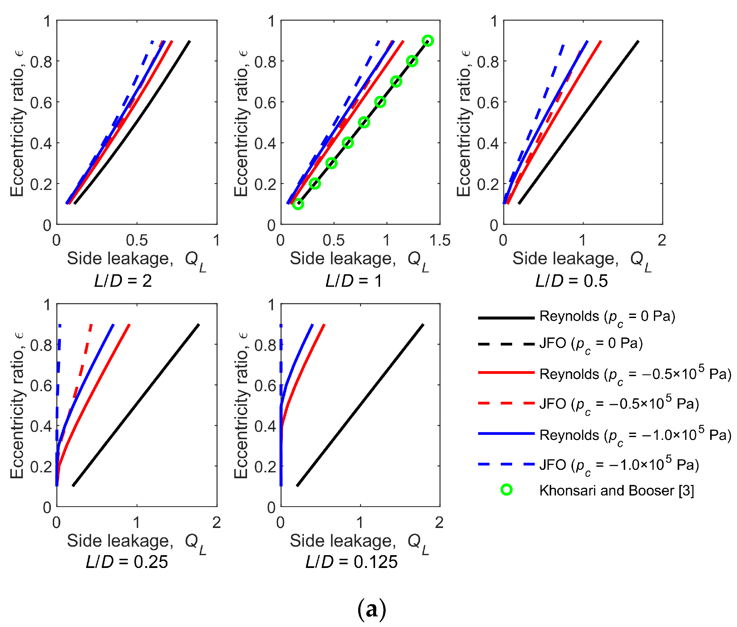
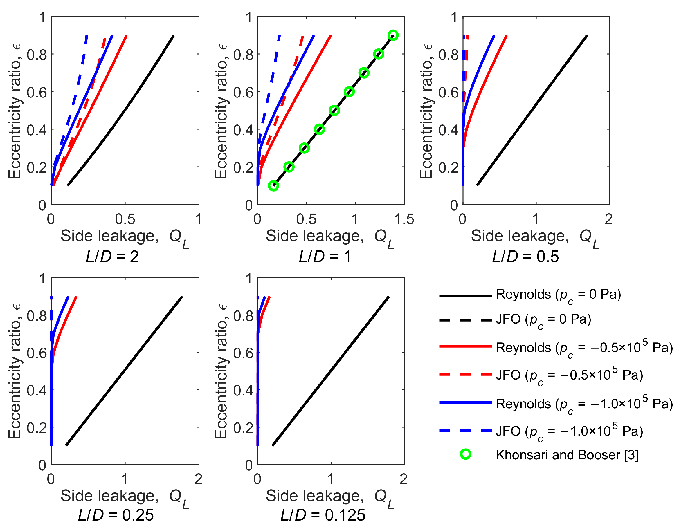
Figure 9 shows the effect of cavitation pressure on the side leakage for the Reynolds model and the JFO theory. The side leakage
QL is expressed by
The side leakage predicted using the Reynolds model is the same to that predicted using the JFO theory for
pc = 0 Pa (the black dotted lines are covered by the black solid lines), and they agree well with the results provided by Khonsari and Booser [
3]. The side leakage decreases with the decreasing cavitation pressure for most cases. This is because the negative gradient means the oil is sucked back into the bearing clearance. In other words, the oil flows away from the positive pressure region and reverses from the negative pressure region. On the other hand, the side leakage remains zero at the low
ε and
L/
D. It is explained by the full Sommerfeld solution: the symmetrical pressure distribution results in an equal outflow and reflux. In addition, the side leakage is overestimated by the Reynolds model, because the pressure gradient in the divergence region is weakened by the underestimated cavitated area, causing the reduction in the inverse flow.
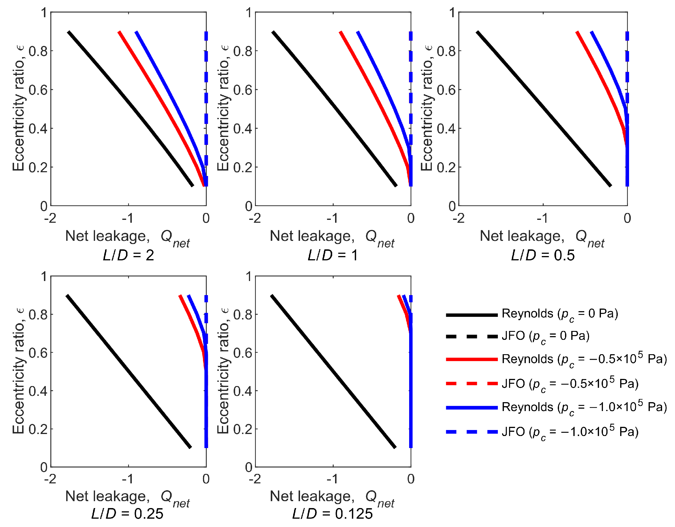
Figure 10 shows the effect of cavitation pressure on the net leakage for the Reynolds model and the JFO theory. The net leakage
Qnet is calculated by
The net leakage represents whether the oil film is mass-conserving or not. (1) All the net leakages predicted using the JFO theory are zero, except the case of the cavitation pressure being 0 Pa (the black dotted lines are covered by the black solid lines). In the case, the oil film pressure distribution predicted using the JFO theory is the same to that predicted using the Reynolds model. Hence, the net leakages of the two methods are equal. (2) The absolute net leakage predicted using the Reynolds model increases with the increase in ε and L/D. That is, the non-mass-conserving phenomenon is amplified as the hydrodynamic effect enhances.
The above analysis is based on the constant bearing number Λ = 10. The following part shows the effect of the bearing number on the bearing characteristics.
Figure 11 shows the effect of the bearing number on the Sommerfeld number for the Reynolds model and the JFO theory. The difference in the Sommerfeld number between different cavitation pressures decreases with the increasing
L/
D,
ε and Λ. In extreme cases, the Sommerfeld number predicted using the Reynolds model is the same to that predicted using the JFO theory at the large
L/
D,
ε and Λ. This is due to the fact that, as the bearing number increases, the hydrodynamic effect enhances, and the cavitation effect is weakened.
The bearing number, as a function of rotational speed, viscosity, and clearance, represents the extent of hydrodynamic effect. Hence, the cavitation effect is weakened with the increased bearing number. The effect of the bearing number on the Sommerfeld number is similar to that on the attitude angle, friction coefficient, and side leakage. Due to the similarity, the corresponding analysis is ignored. These results are provided in
Appendix A.

