Article

Analysis of the Effect of the Slip-Pocket in Single and Double Parallel Bearing Considering Cavitation: A Theoretical Approach

1
Laboratory for Surface Technology and Tribology, Faculty of Engineering Technology, University of Twente Drienerloolaan 5, Postbus 217, 7500 AE Enschede, The Netherlands
2
Laboratory for Engineering Design and Tribology, Department of Mechanical Engineering, University of Diponegoro, Jl. Prof. Soedharto, Tembalang, Semarang 50275, Indonesia
*
Author to whom correspondence should be addressed.
Lubricants 2021, 9(1), 3; https://doi.org/10.3390/lubricants9010003
Submission received: 22 September 2020 / Revised: 14 December 2020 / Accepted: 14 December 2020 / Published: 28 December 2020

Abstract

:
In this paper, based on an analytical approach, the effect of pockets and boundary slip on the hydrodynamic performance of parallel sliding surfaces considering cavitation is investigated. A modified Reynolds theory is developed for solving two kinds of bearings: a single and a double pocket bearing. The performance is compared with respect to the variation of the pocket depth, pocket length, slip, and no-slip situation. The results show that the maximum pressure and load support increases with the reduction in pocket length. The main finding is that the pocket depth reduces the cavitation area. However, in the case of a single pocket, the role of pocket depth is more significant in reducing the cavitation effect than that in the case of a double pocket bearing.

Graphical Abstract

1. Introduction

In past decades, boundary slip has gained significant momentum thanks to researchers. Slip can be induced by (super) hydrophobic surfaces, as demonstrated by [1,2]. Recently, boundary slip has been engineered to improve bearing performance. Slip can occur on the surface if the surface shear stress achieves its critical shear stress [3].
Introducing pocket and boundary slip at a bearing surface is becoming popular in oil-lubricated systems because it has proven to improve the performance in load support and friction. Experimentally, it has been shown that surface texturing improves the load support for mechanical systems with parallel sliding contacts [4,5], cylinder liner contacts [6] and mechanical seals [7]. With the introduction of boundary slip, high load support was highlighted by some works [8,9,10,11,12,13,14,15]. Recently, in addition to surface texturing, the use of an artificial slip surface is also of interest with respect to lubrication. The earliest work on artificial complex slip/no-slip for lubricated parallel sliding devices was reported by Salant and Fortier [16]. They focused on the ability of artificial slip to improve the load support and to reduce the friction force in the absence of the wedge effect. Subsequently, several studies were published confirming the findings of Salant and Fortier [16]. Guo and Wong [17] confirmed that the introduction of so-called tailored boundary slip on the stationary surface of a slider leads to a net pressure build-up. Similarly, Wu et al. [8] studied the behaviour of a slider bearing with mixed slip surface conditions, and their results indicated that convergent, parallel, and even a divergent wedge could provide hydrodynamic load support. Rao [18] investigated the pressure and the shear stress distribution of the single-groove journal and slider bearing. Extended Reynolds equations with slip situations were proposed. Tauviqirrahman et al. [19,20,21,22] explored the potential application of slip as well as texturing in order to enhance the tribological performance behaviour. Their findings indicated that the combined slip/texture bearing improves the load support and friction. However, in their works, particularly in [19,20,21], the cavitation treatment was questionable due to the non-mass-conserving cavitation approach.
Theoretical analysis of a textured surface has been carried out using the Reynolds equation [23,24,25,26] and CFD (Computational Fluid Dynamics) approaches based on Navier−Stokes equations [27,28,29,30,31,32]. Two texture modes were used, namely micro and macro roughness [33,34]. The first mode is based on a single-cell texture configuration [9,24,27,29,32,35,36] and the second one is based on a multi-cell texture pattern [23,25,31,35]. For the two approaches and texturing modes mentioned, cavitation was not considered, so their results may be questionable.
Following the insight on the significance of cavitation, interesting results have been explored by some researchers, for example Fowell et al. [24], Gherca et al. [37], Mao et al. [38], and Galda et al. [39]. On the basis of the Reynolds theory, Fowell et al. [24] investigated in more detail the effect of the mechanism of inlet suction on the performance of textured bearings with pockets to reduce friction. Recent interesting work regarding the effect of texturing was performed by Gherca et al. [37]. Using finite element modelling, they presented the results of hydrodynamic thrust bearings operating in both the steady-state and the transient lubrication regime. It was found that the performance of the bearing is not the same when texturing is applied to the rotor and the stator. Mao et al. [38] proposed an analytical model coupled with the wedge effect for predicting cavitation characteristics under sliding motion. Optimization was also performed to improve the performance of lubricated textured components. Galda et al. [39] found, based on an experimental approach, that dimples improved the tribological characteristics under starved lubrication conditions at low sliding speeds. It was also found that the beneficial effect of dimples was more significant at a lower load. Later, Kasem et al. [40] studied experimentally the effect of low depth surface on friction reduction. They found that dimples with smaller diameter lead to a significant decrease in the coefficient of friction in comparison with the dimples with a larger diameter.
Based on the previously published works, the analysis was conducted for a one-dimensional parallel sliding contact, ignoring the cavitation effect. Wall slip, surface texturing, and cavitation have a significant effect on the bearing’s characteristics. Bayada and Meurisse [12] showed the importance of the cavitation model in the analysis of slip/no-slip hydrodynamic contacts. Fortier et al. [41] presented the numerical analysis of a journal bearing using a modified slip length model and mass-conserving algorithm. The results illustrated high load support and low friction using a heterogeneous slip/no-slip bearing surface. Based on the modified slip length model and cavitation model, Wang and Lu [42] presented results for a two-dimensional sleeve bearing.
Additionally, the effect of boundary slip and surface texturing was also studied, for example [8,16,19,20,43,44,45,46,47,48], but ignoring the cavitation effect and mostly using a non-mass-conservation cavitation equation. In the present work, it will be shown that cavitation has a strong influence on performance and unrealistic conclusions may be drawn if the cavitation is ignored. A few publications considered texturing and slip in lubricated contacts considering cavitation [42]. Another interesting study dealing with slip combined with texturing was reported by Biancofiore et al. [49]. In the presence of cavitation, the authors proposed a stable numerical model that can be used to study the slip-lubricated contact. The guidelines to improve and optimize the design of textured superoleophobic surfaces have been highlighted.
The novel contribution of the present work is to develop a new lubrication model including mass-conserving cavitation based on an extended Reynolds approach. In this paper, the texturing configurations of single- and double-grooved pockets are of particular interest. The correlation between the texturing parameters with slip and cavitation on the load-carrying capacity is the main concern.

2. Mathematical Model

The textured bearing configurations considered in this paper are shown in Figure 1 and Figure 2. Figure 1 and Figure 2 represent a single- and double-pocket slider slip bearing. Here, the slip condition is assumed to occur on the top edge of the pocket. The slip condition is indicated by the rollers, as shown in Figure 1 and Figure 2. It is noted that for the case of a double pocket, the first pocket depth is set to be lower than the second pocket depth. In this work, the pocket depth is varied for the first pocket, while the pocket depth of the second pocket is kept constant. For calculations, the inlet and outlet pressures are set to atmospheric pressure. The slip condition is represented by the slip coefficient, α of 0.02 m2s/kg, while for the sliding velocity, U, it is set to 1 m/s.
In practice, the boundary slip can be induced by modifying the roughness and/or wettability. From the physical point of view, the slip is observed as the condition in which the velocity of the fluid at the interface is not equal to surface velocity. This is different from the no-slip condition. In this way, the classical assumption stated that the fluid velocity at the interface has the same value as the surface velocity. To solve the lubrication problem, an analytical equation is proposed by extending the Reynolds theory, including the cavitation and the slip. The methodology used in the derivation of the extended Reynolds equation is quite similar to that employed by Fowell et al. [24] and is given in detail in Appendix A.
Based on Figure 1 and Figure 2, the mathematical flow rate can be derived. For flow rate, a set of governing equations can be obtained (by using the pressure continuity at the boundaries Equations (A1)–(A24), see Appendix A). Solving the set of governing equations, the analytical solution for the single pocket with slip is given in Equation (1) and for the double pocket with slip in Equations (2) and (3).
h p 3 h p + 4 μ α h h p + μ α h ( P 3 P c a v X b ) = 6 μ U ( h p h p + 2 μ α h h p + μ α h h o ) h o 3 ( P a t m P c a v a )
h p 1 3 h p 1 + 4 μ α h h p 1 + μ α h ( P 3 P c a v X b ) = 6 μ U ( h p 1 h p 1 + 2 μ α h h p 1 + μ α h h o ) h o 3 ( P c a v P 3 c )
h p 2 3 h p 2 + 4 μ α h h p 2 + μ α h ( P 5 P c a v X d ) = 6 μ U ( h p 2 h p 2 + 2 μ α h h p 2 + μ α h h o ) h o 3 ( P a t m P 5 e )

3. Methodology

In the present work, the occurrence of cavitation is assumed to take place at zero pressure. The cavitation area in the first pocket is denoted by CLb in which CLb = bXb and the cavitation area in the second pocket is defined by CLd in which CLd = dXd. This means that when the cavitation occurs, CL is larger than zero.
The solution for the lubrication problem for a pocketed slider bearing (single and double pocket) is as follows:
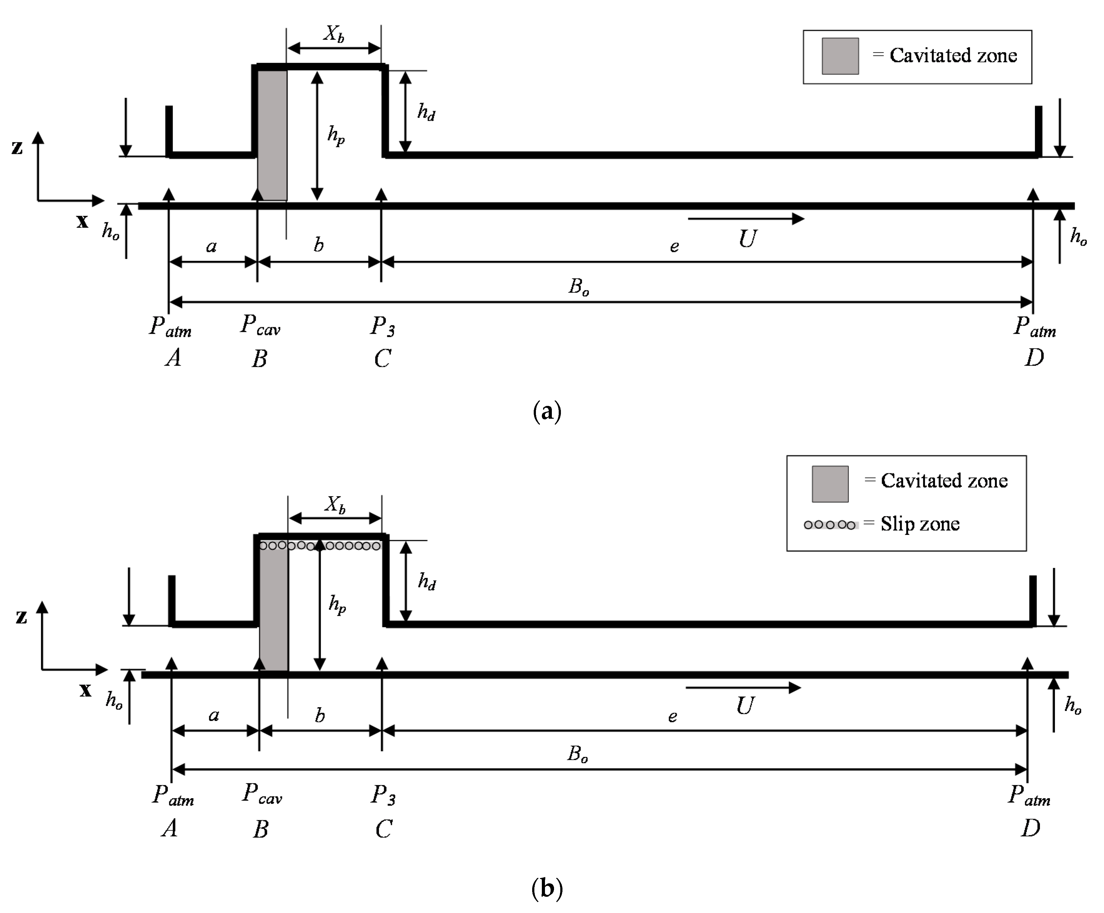
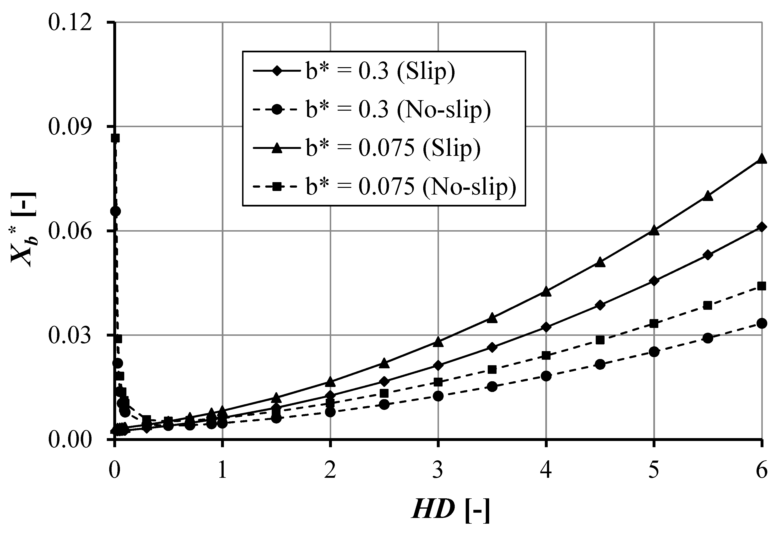
  • Single pocket. For all computations, the cavitation phenomenon is assumed to occur in the pocket. Here, the cavitation equations (Equations (A1)–(A11) of Appendix A) are used to obtain Xb (non-cavitated region in the pocket as seen in Figure 1) Xb is then used as an indicator of whether cavitation occurs or not. Cavitation in a pocket occurs if 0 < Xb < b, where b is the pocket length.
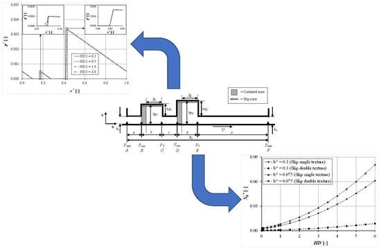
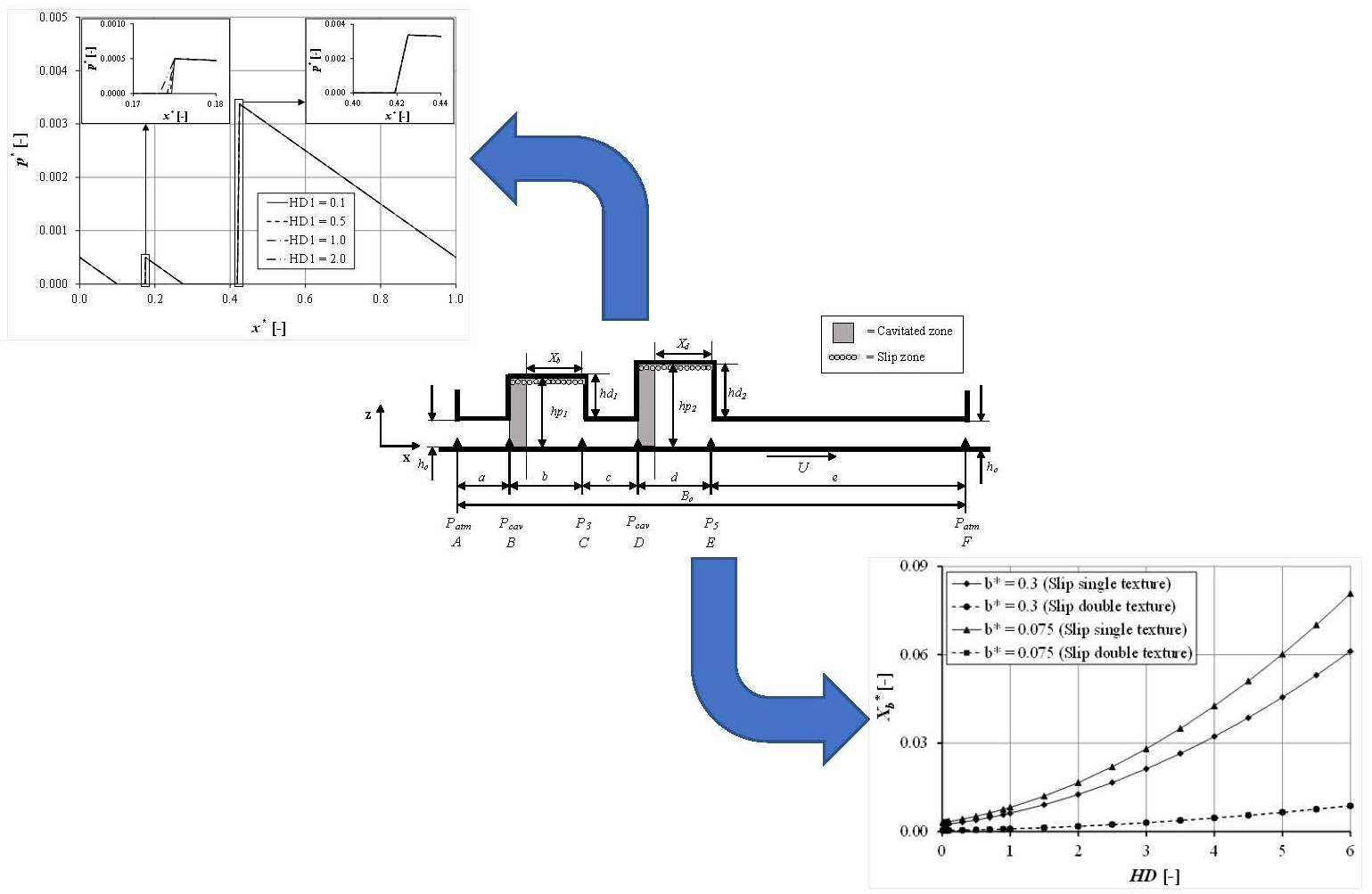
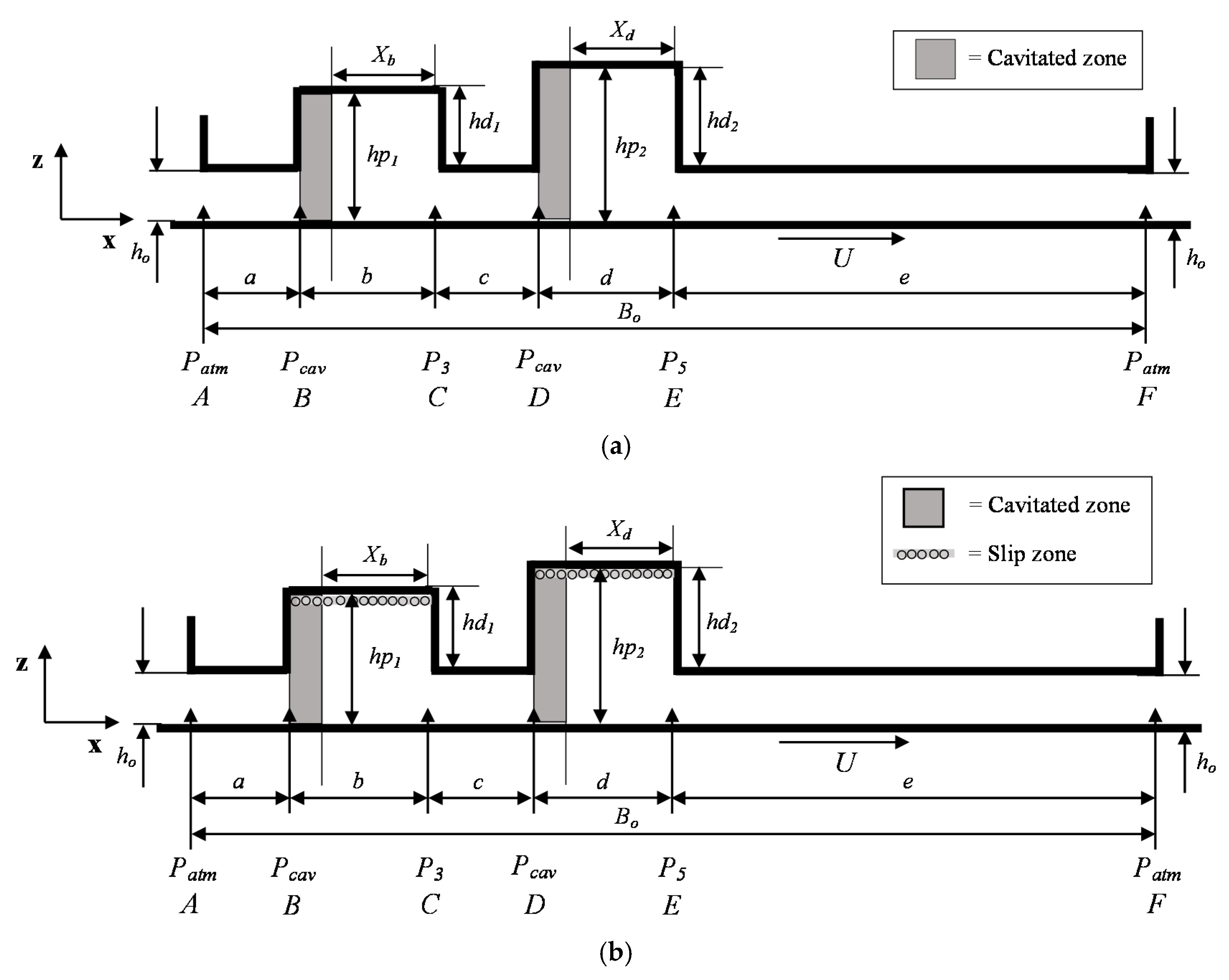
  • Double pocket. For all computations, the cavitation phenomenon is assumed to occur in the first and second pockets of the bearing. The cavitation equations (Equations (A12)–(A24), see Appendix A) to obtain Xb and Xd (a non-cavitated region in the first and second pockets as indicated in Figure 2) are used. Xb and Xd will then be used as an indicator of whether cavitation occurs or not. It should be noted that cavitation in the first pocket occurs if 0 < Xb < b, where b is the first pocket length and cavitation in second pocket occurs if 0 < Xd < d, where d is the second pocket length.
The validity of the Reynolds equation in lubricated contacts with surface texturing has been discussed in the literature. The limits of this equation are given in [31]. In this study, care has been taken to ensure that the configurations considered here fall within the validity domain of the Reynolds equation for the case of both single- and double-pocket texturing. As a note, the model developed here (Equations (1)–(3)) has been validated, as shown in Appendix B.

4. Results and Discussion

In this section, the effect of texturing and cavitation on a single-pocketed bearing and on a double-pocketed bearing is studied. It should be noted that for the last case, only the first pocket is of main interest. It means that the variation of the texturing parameters is applied to the first pocket. The cavitation effect on the lubrication of the second pocket is also explored to analyze the correlation of the lubrication characteristics between the first and second pockets.

4.1. Case of Single-Pocketed Bearing

Table 1 depicts the dimension of the single-pocket bearing considered here. As a note, the pocket depth and length are of particular interest in this research. As seen in Table 1, when the pocket length is varied, based on Figure 1, the exit land length changes following the constraint of the total length.

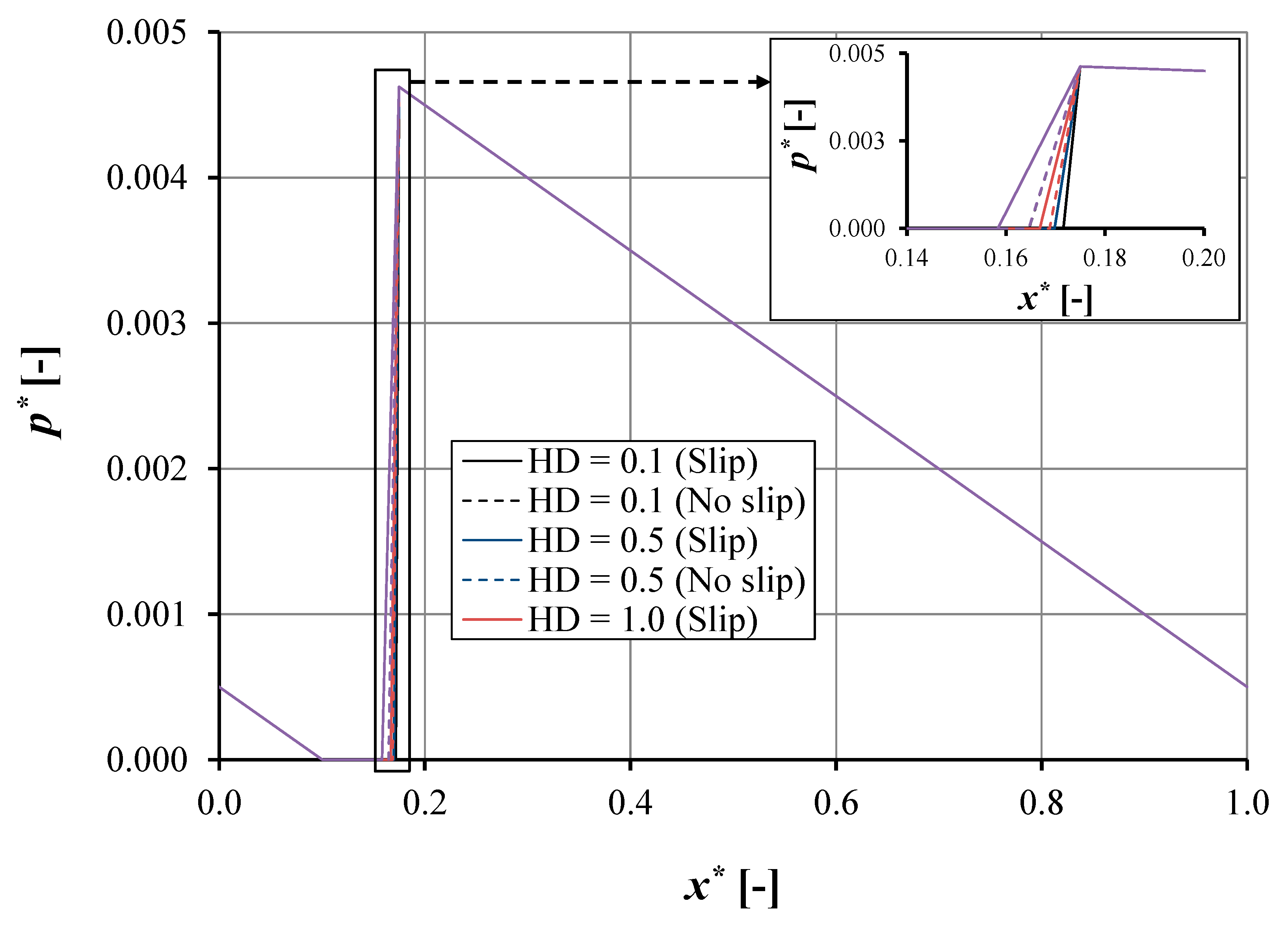
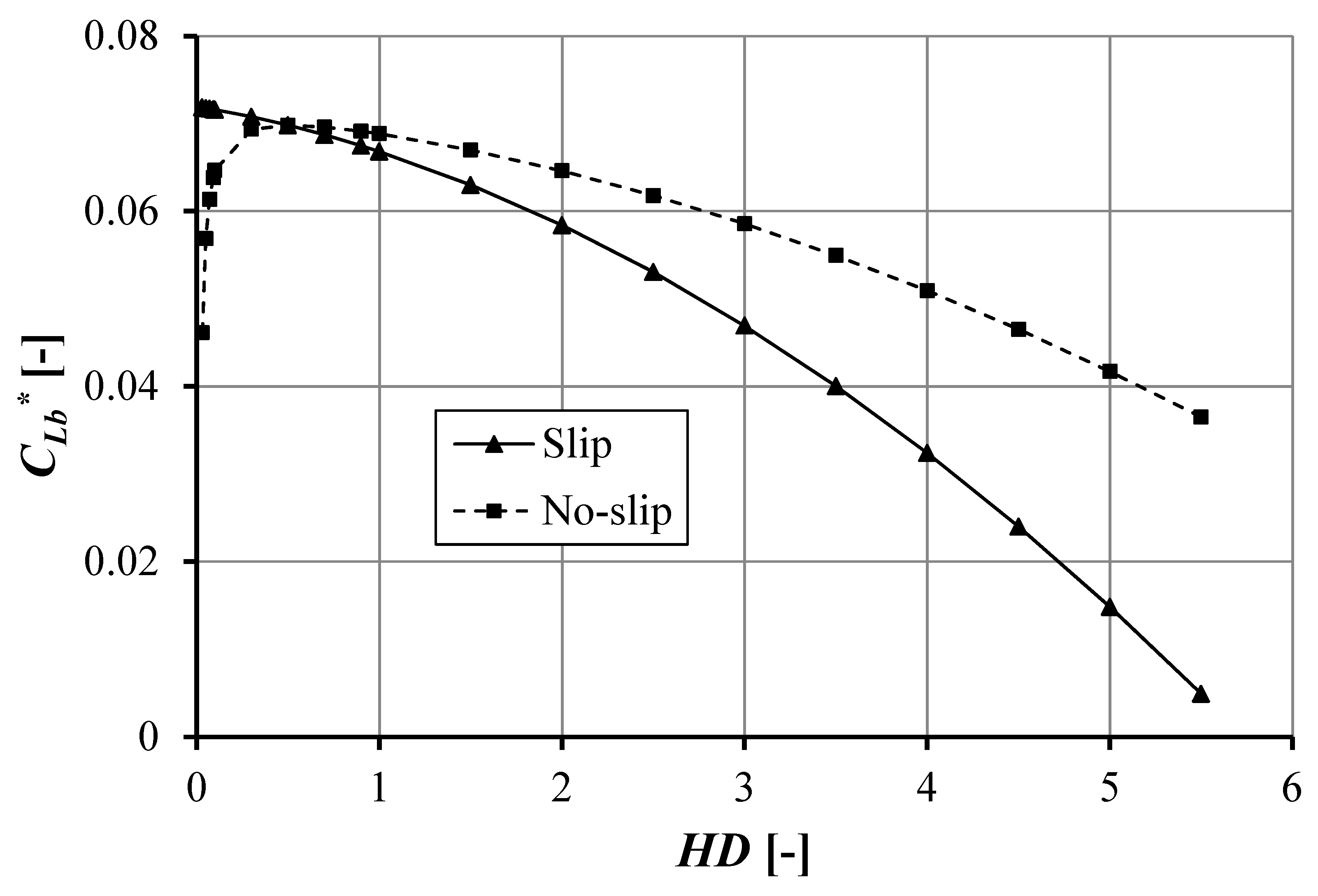
4.1.1. Effect of Pocket Depth with Low Pocket Length

Figure 3 depicts the comparison of the pressure distribution of the single-pocketed bearing between the slip case and the no-slip case varying the pocket depth. In this section, the parameter HD is introduced as the normalized pocket depth. HD is defined as the ratio of pocket depth, hd, over the land film thickness, ho. Furthermore, the load support, w, is of particular interest. Here, w is defined as the integration of the pressure over the surface area.
In this discussion, the slip case refers to the pocketed bearing in which slip is allowed on the top edge of the pocket (Figure 1) by setting the slip coefficient as α = 0.02 m2s/kg. It should be noted that the slip coefficient chosen is the optimal value with respect to the maximum load support based on published works, both experimental [10,11] and numerical [12].
Several specific features can be observed based on Figure 3. Firstly, for the single-pocketed bearing for both the slip case and no-slip case, the pressure distribution shows similar trends for all pocket depth values studied. At the inlet, the pressure decreases to cavitation pressure for all configurations. This indicates that if the pocket is not placed at the inlet length, the suction mechanism will, as discussed by Bayada et al. [12] dominate the bearing even if boundary slip is employed. Secondly, it is easy to observe that cavitation occurs in the bearing for both cases (slip and no-slip). This is characterized by the presence of the cavitation area as marked in Figure 3. In the inset of Figure 3 regarding the slip case, it can be observed that a high pocket depth, HD, leads to a decrease in the cavitation area. However, for the no-slip case, a low HD behaves differently.
In detail, dealing with the pocket depth, it can be seen that in the case of a pocketed bearing with slip the pocket depth will affect the cavitation area, CLb, considerably. This trend also prevails for the no-slip case. Figure 4 reflects the effect of pocket depth on the cavitation area for both slip and no-slip pocketed cases. For the slip case, increasing the pocket depth will decrease the CLb considerably. It is very interesting to note that cavitation exists when HD = 0, which is associated with the smooth parallel sliding surface. This result matches well with published work [12].
From a design and manufacturing point of view, to have the condition of no-slip in the inlet is not recommended because it leads to cavitation, which may reduce the lubrication performance of the sliding contact: for the no-slip case, the increase in HD will produce an increase-then-decrease profile of the cavitation area, CLb. This indicates that there will be an optimum value for HD after which an increase in HD will reduce the CLb significantly. Below this optimal HD, a decrease in HD will also reduce the CLb considerably. This is a contrary result to that of the slip case. Based on Figure 4, it is seen that the critical HD is around 0.5. Analyzing Figure 4, boundary slip reduces CLb more than that for no-slip (up to 86.57%). However, this condition prevails when HD is larger than the critical HD. For example, for HD = 4, compared with the no-slip bearing, slip gives a 36.40% lower value in CLb, and if this result is associated with the load support W*, the improvement in W* by slip is around 2.47% larger.
Thirdly, employing boundary slip on the pocket does not enhance the peak dimensionless pressure very much. For both cases (slip and no-slip), the peak hydrodynamic pressure refers to the same value, i.e., p* 0.0046. However, if the slip effect is subjected to the lubrication performance (load support in this case), the slip has a positive effect. The predicted load support for all cases considered in Figure 1 is summarized in Table 2. Based on Table 2, for all pocket depths considered here, the load support predicted by a pocketed bearing with slip has a higher value than that without slip. From a physical point of view, this is because the cavitation area is reduced by employing the slip, as mentioned earlier, and thus the integration of pressure over the surface area becomes larger.

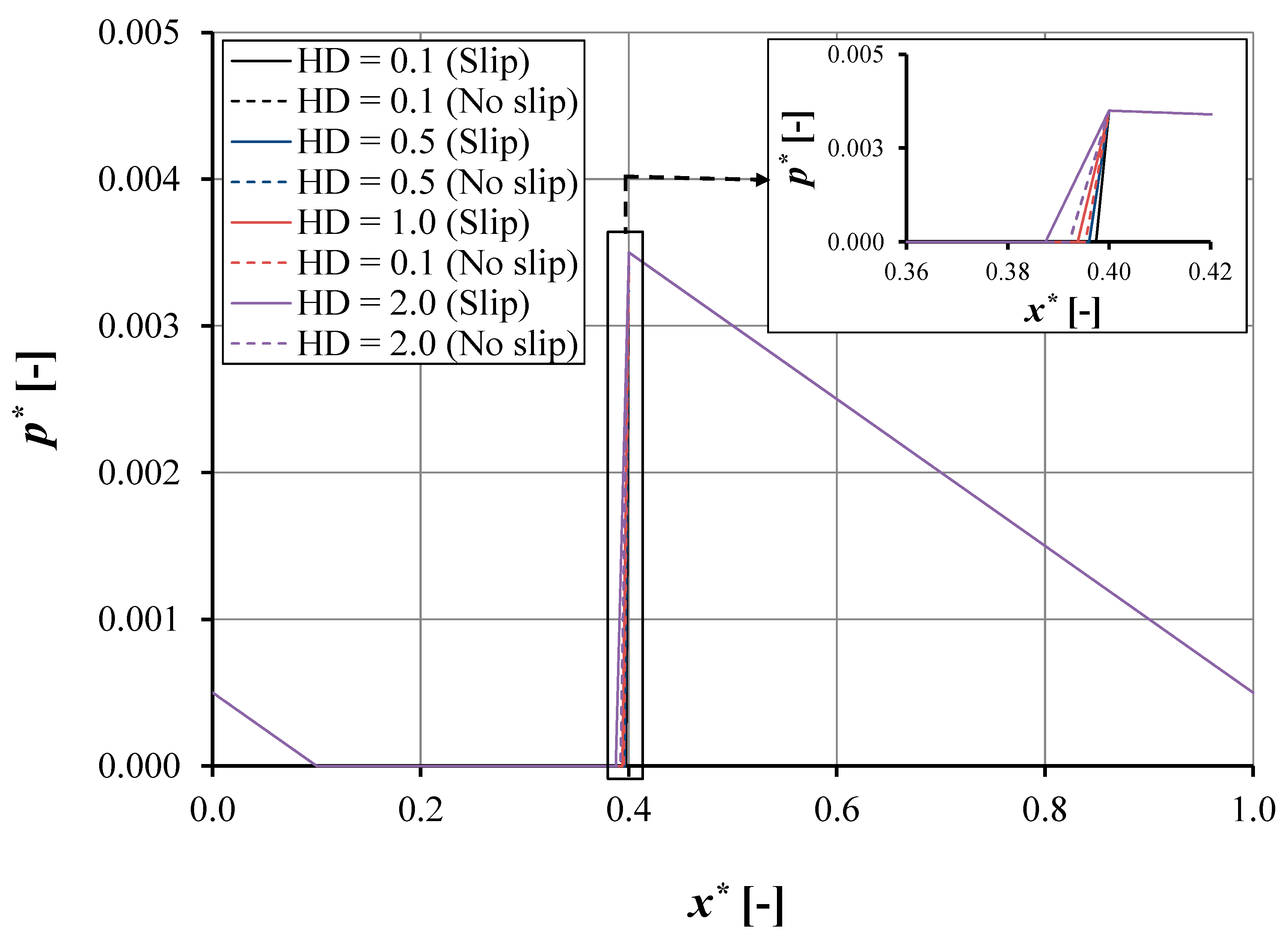
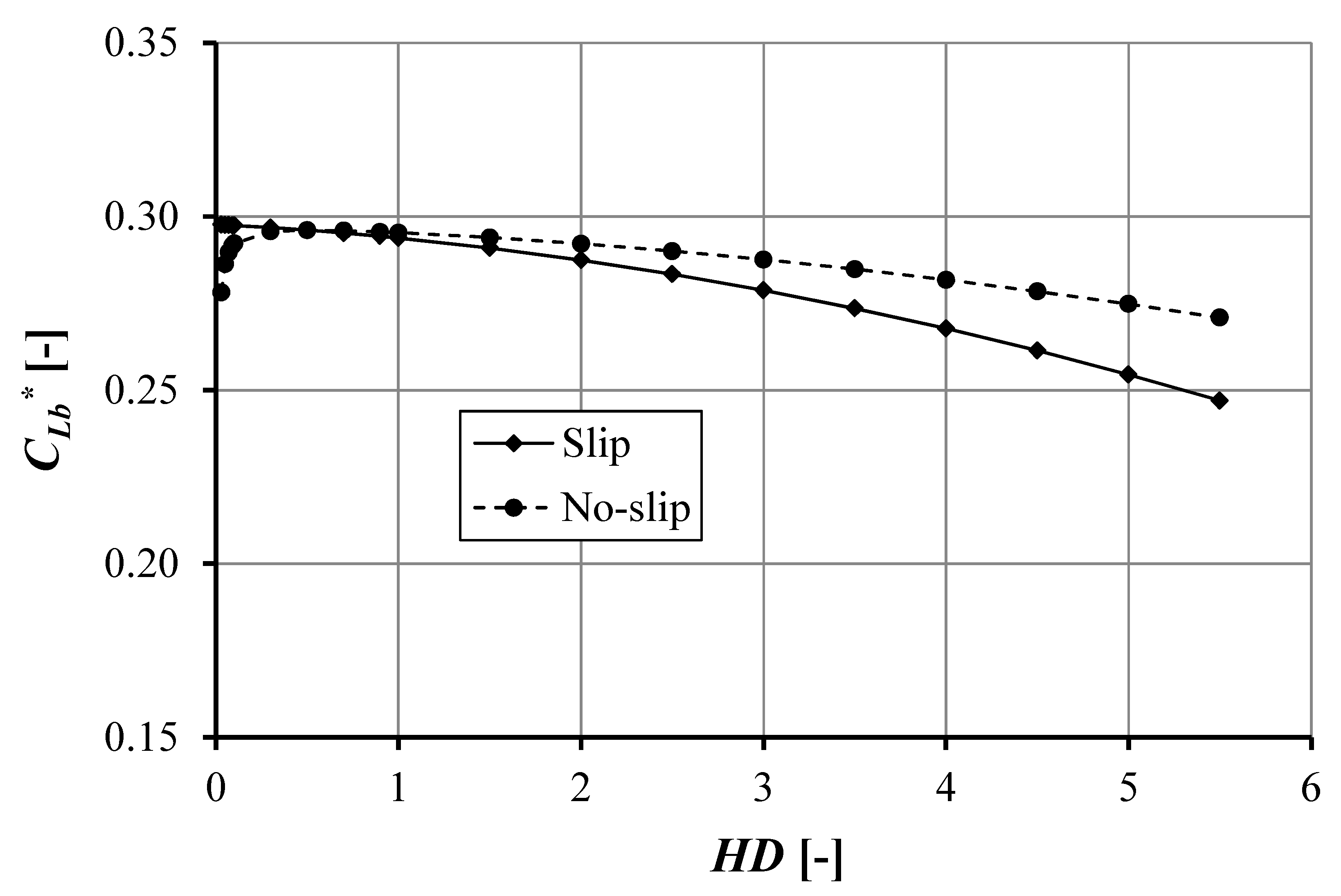
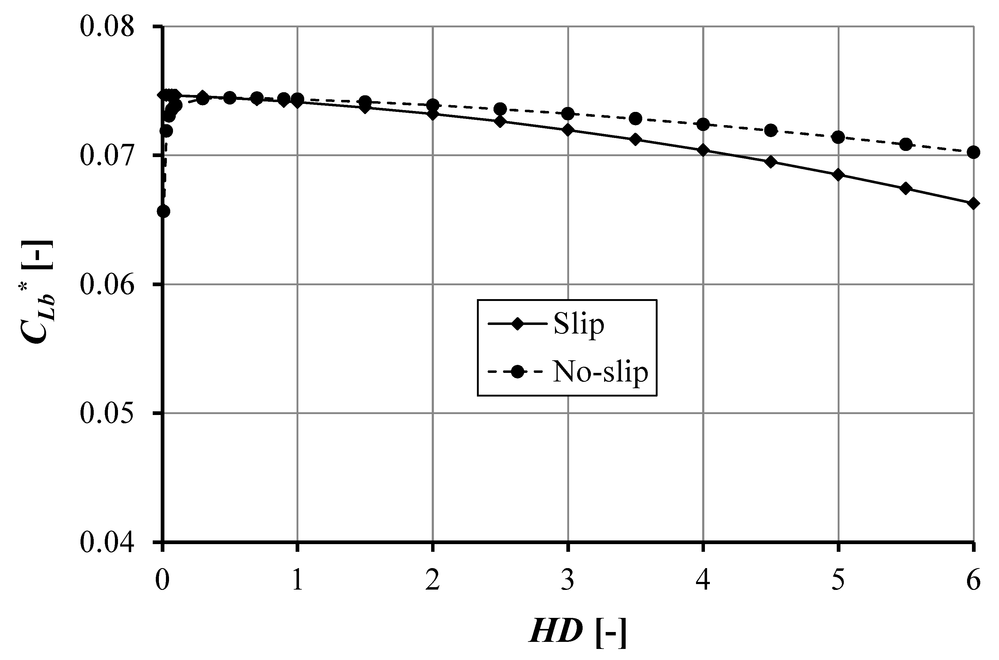
4.1.2. Effect of Pocket Depth with High Pocket Length

Figure 5 shows the comparison of the pressure distribution of the single-pocketed bearing between the slip case and the no-slip case varying the pocket depth with high pocket length, b = 0.006 m. In general, the pressure distribution is similar to the pressure profile for low b, as depicted in Figure 3. However, some specific features can be highlighted from Figure 5.
Firstly, it can be stated that a higher b, results in a lower value for the maximum pressure. The most likely explanation is that increasing the pocket length will reduce the exit land length, while the maximum pressure, P3, is a function of inlet and exit length (see Equation (A8) in the Appendix A). In this case of high b (300% higher than the first case, i.e., low b), P3* reaches 0.0035 (or 31.43% lower). Secondly, the value of the maximum pressure, P3, is not affected by varying the pocket depth, HD. As mentioned earlier, the pocket length has a significant role in influencing the cavitation area.
Figure 6 depicts the length of the cavitation area for the slip and no-slip condition. In the no-slip condition, the optimum cavitation area, CLb*, is 0.2975 for HD = 0.5. The cavitation area decreases with increasing HD. For the slip case, increasing the pocket depth will decrease CLb. It is very interesting to note that cavitation exists when HD = 0, which is associated with a smooth (non-textured) parallel sliding surface. Figure 6 shows that the cavitation area has the same value for pocket depth, i.e., HD equal to 0.5, while for the case of the slip and no-slip condition, if HD = 4, the difference in cavitation area is around 5%. Therefore, it can be said that the introduction of the cavitation area is reduced.
Table 3 shows the load support for the slip and no-slip condition with variations of pocket depth, HD. For the slip condition, the load support increases with increasing pocket depth, HD, while the maximum load support W* is 0.000747 if the pocket depth HD = 2.0. For the no-slip condition, the minimum load support W* is 0.000732 for a pocket depth, HD, of 0.05. The maximum load support W* is 0.000739 when the pocket depth HD is 1.0 or 2.0. The result is similar to the research by Bayada et al. [12] for the case in which the slip is not placed on the inlet length, i.e., load support increased significantly. From the table, it can be seen that when pocket depth HD = 0.5, the slip and no-slip conditions generate the same load support. It can be said that HD becomes optimal in the case of the no-slip when HD is set to 0.5.

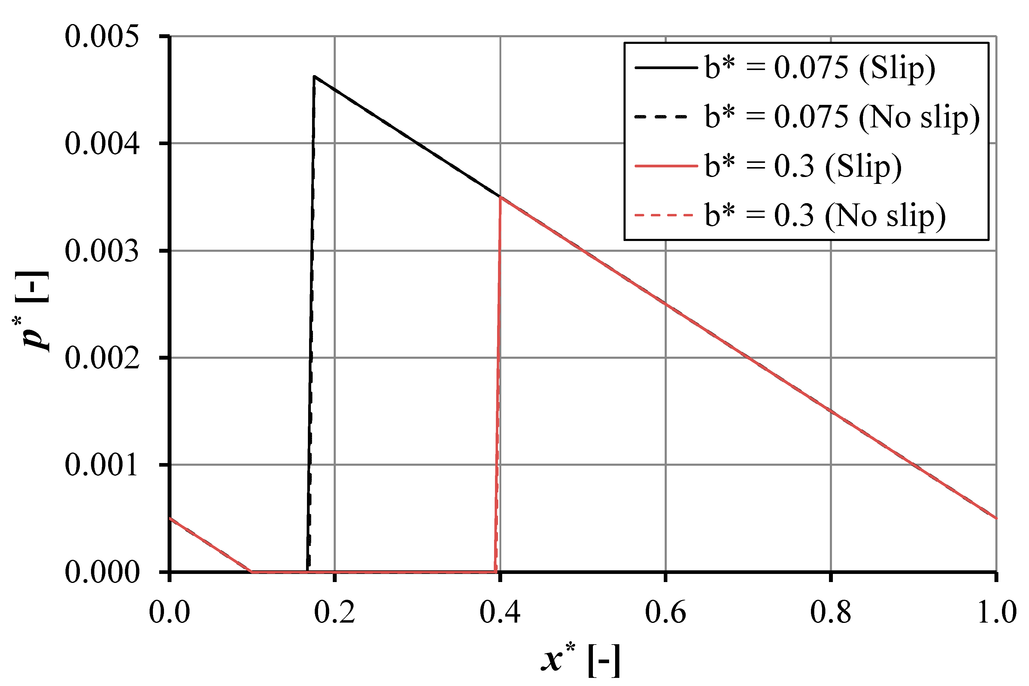
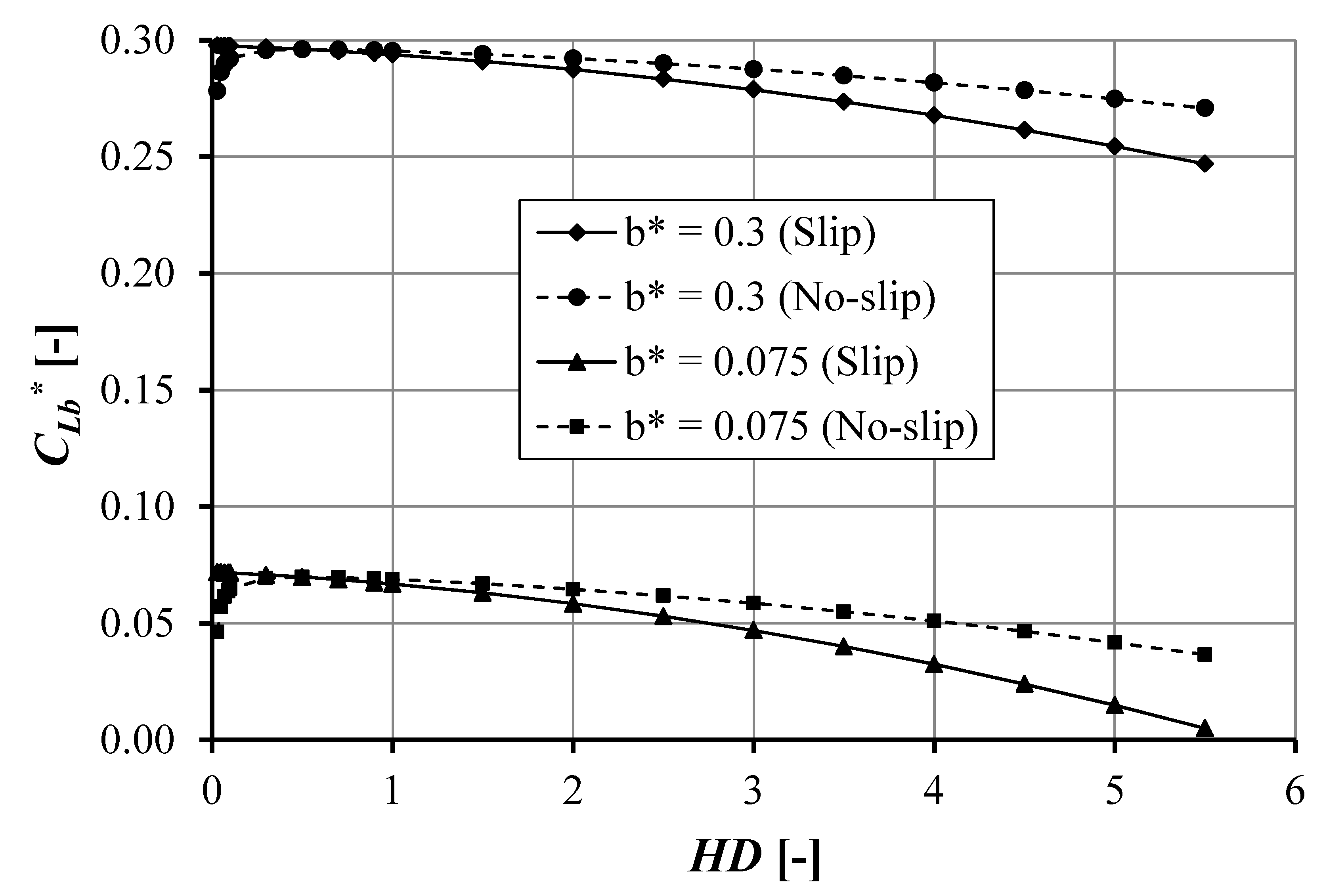
4.1.3. Effect of Pocket Length, b

Figure 7 shows the pressure distribution for the slip and no-slip condition with pocket depth HD = 1, pocket length b = 0.0015 and 0.006 m. The pressure distribution for the slip and no-slip condition shows a similar trend. The pressure distribution decreases to the cavitation pressure, then increases to maximum pressure P3, and decreases toward the atmosphere pressure at the exit land length. The maximum pressure, P3, is of particular interest, it decreases with increasing pocket length. From the figure, it can be seen that the maximum pressure distribution, P3, for different pocket lengths, b, has the same gradient; thus, minimizing the pocket length will increase the maximum pressure, P3, in the cavitation condition. However, it should be noted that there is a threshold in this increase in P3 as a function of a decreasing pocket length, b. When cavitation does not occur for a specific pocket pattern, in particular, with a very low pocket length, the maximum pressure may reduce. For a more detailed discussion about this threshold, the reader is referred to reference [49]. The slip condition will decrease the cavitation area. However, the reduction in cavitation area is not significant. The slip condition will not significantly affect the maximum pressure distribution, P3, for the same pocket length.
Figure 8 gives the cavitation area as a function of pocket depth. The cavitation area increases with increasing pocket length. However, the cavitation area shows a similar trend with the pocket depth for the slip and the no-slip condition. Figure 9 depicts the no-cavitation area, Xb, as a function of pocket depth. For the slip condition, the no-cavitation area increases with increasing pocket depth, HD. However, it decreases with increasing pocket length, b. In other words, the load support will increase for a lower pocket length, b, and a higher pocket depth, HD. In the no-slip condition, a minimum Xb occurs when the pocket length, HD, is equal to approximately 0.5. For HD > 0.5, Xb increases with increasing pocket depth, HD. As for the slip condition, on increasing the pocket length, b, for the no-slip condition Xb will decrease. From Figure 9, it can be seen that the slip condition improves the no-cavitation area. The result is consistent with the results mentioned earlier and the work of Bayada et al. [12], i.e., slip will reduce the cavitation area.

4.2. Case of Double-Pocketed Bearing

Based on Figure 2, the main interest of this work is the effect of pocket depth as well as the pocket length of the first pocket on the lubrication characteristics of parallel sliding surfaces. It is noted that for the second pocket, the dimensions are assumed to be constant. The slip is applied at the top of the pocket for both the first and second pocket. Varying the pocket length for the first pocket will change the exit land length, while the pocket length of the second pocket is constant. Table 4 shows the characteristics of the double-pocket bearing.

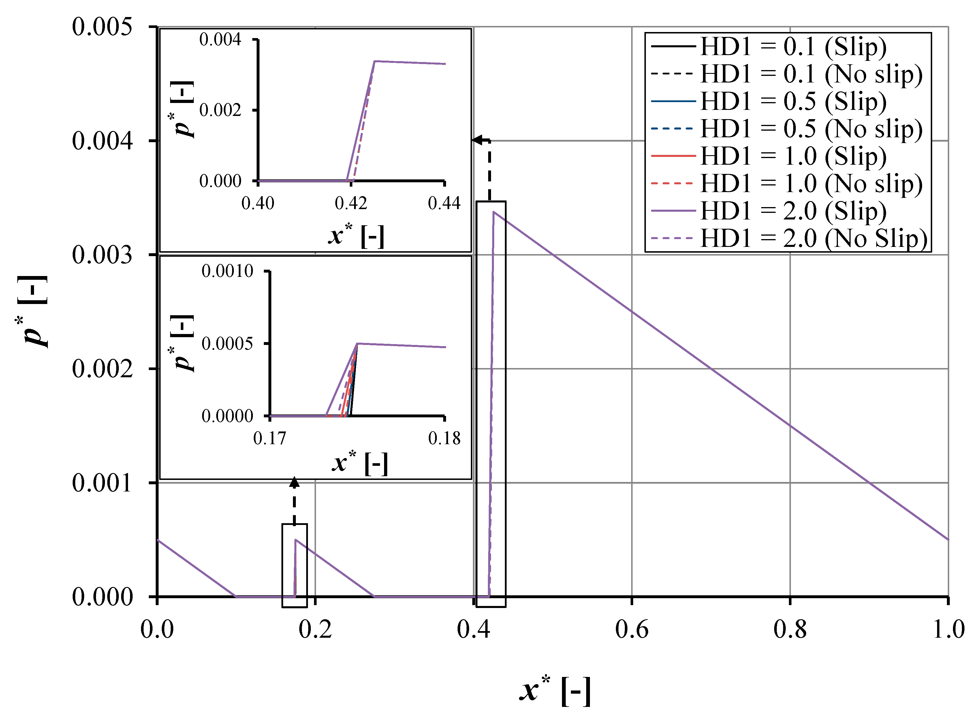
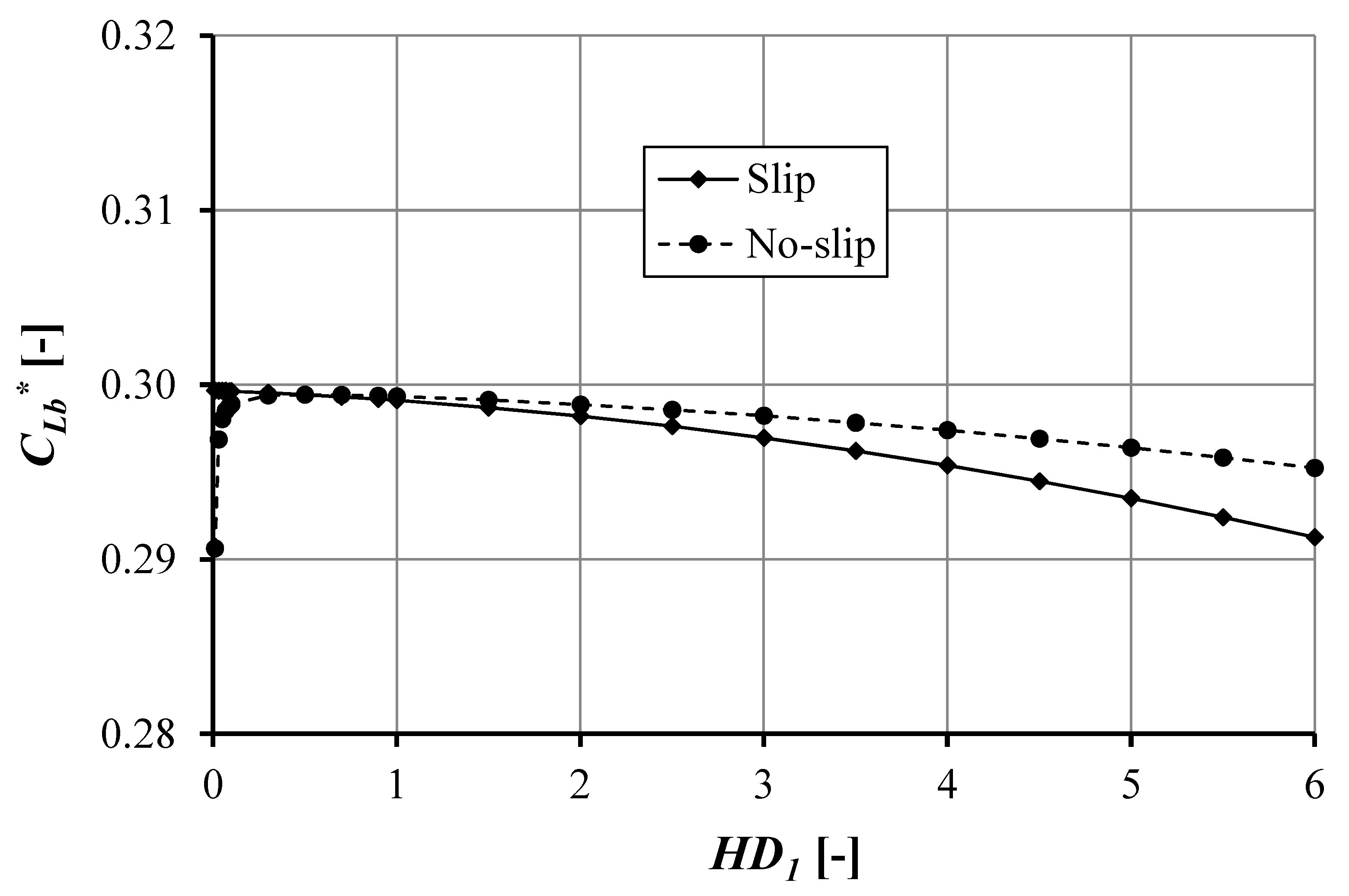
4.2.1. Effect of First Pocket Depth

Figure 10 shows the pressure distribution of the double pocket bearing (Figure 2) for both the slip and the no-slip condition. The figure describes some findings: firstly, the pressure distribution shows a similar trend for both the slip and the no-slip condition. The maximum pressure, P5, occurs in the second pocket, the value of the maximum pressure is the same for the slip or no-slip condition (P5* = 0.0034). The maximum pressure in the first pocket is equal to the atmosphere pressure. Secondly, the pressure distribution in the first or second pocket is not influenced by the first pocket depth, HD1. The variation of the first pocket depth, HD1, will influence the length of the cavitation area in the first pocket (see inset of Figure 10). However, it does not affect the cavitation area in the second pocket (see Equation (A24) in Appendix A). Consequently, the length of the cavitation area is not a function of the first pocket depth, HD1. Thirdly, the slip condition will affect the cavitation area in the first or second pocket, in other words it reduces the cavitation area.
Figure 11 depicts the length of the cavitation area in the first pocket as a function of pocket depth. The length of the cavitation area is similar to that of the single-pocketed bearing for both the slip and the no-slip situation. The maximum pocket length (CLb) occurs when pocket depth HD1 = 0.5, that is 0.0746. The cavitation area decreases as a function of pocket depth, HD1. In the slip condition, the length of the cavitation area decreases with increasing pocket depth, HD1. If the pocket depth, HD1, is equal to zero, the length of the cavitation area still remains large. However, for the no-slip condition, a contrary result is observed; the length of the cavitation area decreases significantly, which means that the cavitation will vanish if the pocket depth is reduced to up nearly the smooth condition.
Table 5 gives the value of the load support of the double-pocket bearing with pocket length b = 0.0015 m. The load support for the slip condition increases with increasing pocket depth, HD1. The maximum dimensionless load support for the slip situation is 0.0006746 when the pocket depth, HD1 = 2.0. Contrary to the slip condition, the no-slip condition has a minimum load support for HD1 = 0.5. The maximum load support for the no-slip condition is 0.0006719 for HD1 = 0.1 and 2.0. The difference in maximum load support between the slip and no-slip condition is 0.40% for HD1 = 2.0. The result is similar to the research of Bayada et al. [12]: there is a small increase in load support if slip is not provided in the inlet suction. The load support for the slip condition is higher than that for the no-slip situation. In the second pocket, the length of the cavitation area for the no-slip condition (CLd* = 0.00291) is larger than for the slip situation (CLd* = 0.00288).

4.2.2. Effect of First Pocket Length

Figure 12 shows the pressure distribution as a function of coordinate in sliding direction for the double-pocket bearing with a first pocket length of 0.006 m. The pressure distribution shows a similar trend for both the slip and the no-slip condition. The maximum pressure in the first pocket, P3, is equal to the atmosphere pressure. The second pocket, P5, is the same for the slip and the no-slip situation (P5* = 0.0023). A different pocket depth, HD1, affects the length of cavitation in the first pocket for the slip and the no-slip situation (see insert Figure 12). However, it does not influence the pressure distribution in the second pocket.
Figure 13 depicts the cavitation area in the first pocket as a function of pocket depth, HD1. For the slip situation, the cavitation area decreases as a function of the pocket depth. However, the cavitation area has a maximum value for the no-slip situation (HD1 = 0.5) and decreases with increasing pocket depth, HD1. The difference in the cavitation area for the slip and no-slip condition is around 0.67% for HD1 = 4.0. The slip condition affects the cavitation area in the first and second pocket. However, the first pocket depth does not influence the cavitation area in the second pocket. The length of the cavitation area in the second pocket CLd is 0.004 for the slip situation and 0.003 for the no-slip condition. As a consequence, this will affect the load support.
Table 6 shows the load support of the double-pocket bearing with pocket length b = 0.006 m. The load support increases with increasing first pocket depth, HD1, for the slip situation. The maximum load support W* is 0.0000362 for HD1 = 2.0. For the no-slip situation, the maximum load support is 0.0000349 in HD1 = 2.0. The difference in maximum load support is 2.56% for the slip and the no-slip situation. The load support for the slip situation is higher than for the no-slip condition. The second cavitation area influences the load support. The cavitation area, CLd, is 0.00292 for the no-slip situation and is equal to that for the slip condition (see Figure 12).

4.2.3. Comparison of Pocket Length in Double Texture

Figure 14 shows a comparison of the pressure distribution as a function of pocket length for the slip and no-slip situation. Reducing the first pocket length improves the maximum pressure distribution, P5. The increasing pressure distribution has the same slope gradient. Consequently, the maximum pressure can be predicted as long as the cavitation condition exists. It can be observed that the maximum pressure distribution of the first pocket, P3, is equal to the atmospheric pressure.
Figure 15 reflects the no cavitation area of the first pocket, Xb, as a function of the first pocket depth for the slip and no-slip situation. The figure also depicts that the no-cavitation area of the first pocket is not affected by the first pocket length. Slip and pocket depth improve Xb. For the slip situation, Xb increases with increasing pocket depth. For very small HD1, the no-cavitation area is close to zero. However, the no-slip situation has a minimum Xb for HD1 = 0.5, and it increases with increasing HD1. For HD1 = 0.0 (i.e., smooth surface), Xd does not exist. It can be observed that the slip trends for varying b coincide with each other. These trends also occur for the no-slip condition.
Figure 16 shows the comparison of the no-cavitation area, Xb, between the single- and double-pocket bearing for the slip and no-slip situation, respectively. It can be observed that Xb in the case of the double pocket is not affected by pocket length for both the slip and the no-slip condition. In other words, such a pocket pattern gives the same Xb profile. Another interesting result is that Xb for the case of the double-pocket bearing is smaller than that of the single pocket bearing for both slip and no-slip conditions. The no cavitation area increases with larger first pocket length, HD1, and is close to zero for small HD1. It can be observed that the no-slip trends for varying b coincide with each other as shown in Figure 16.

5. Conclusions

In the present work, the mechanism of the inlet suction using single and double pockets of a lubricated contact (with and without slip) considering cavitation condition was analyzed. A one-dimensional analytical model has been developed for both a single- and a double-pocketed bearing with boundary slip, including cavitation. The following conclusions summarize the results of the present study:
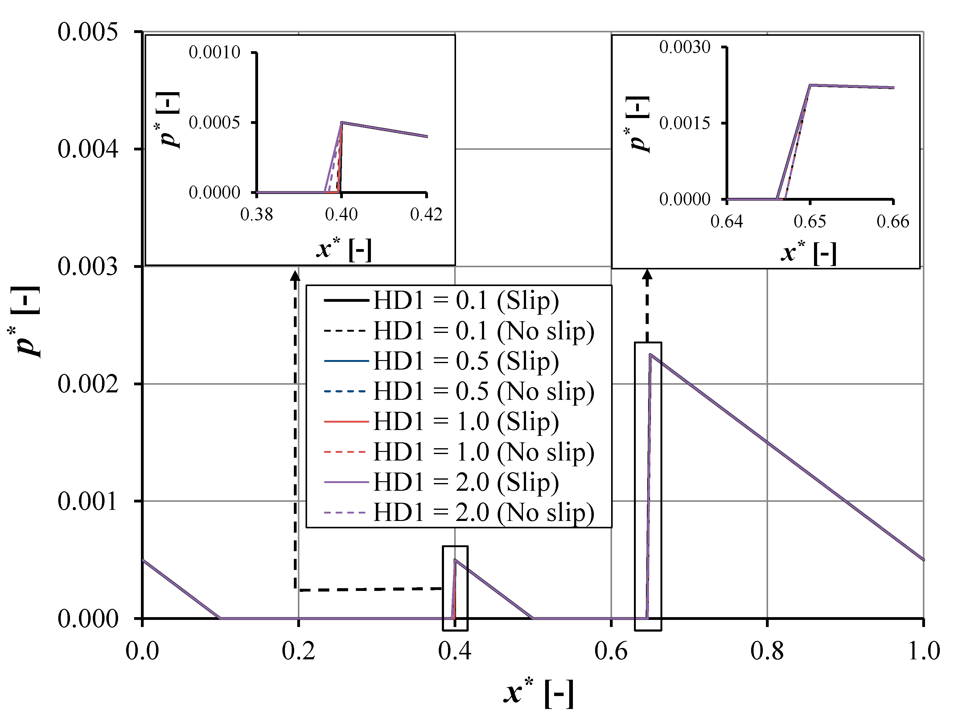
  • The pocket depth has a strong effect on pressure and load support. For the slip condition, increasing the pocket depth increases the load support. However, for the no-slip condition, the optimal pocket depth is observed; when this value is exceeded, the reduced load support is found.
  • When the slip condition is applied on the top edge of the pocket, the slip effect is not as significant as in the no-slip condition. The load support improvement is no more than 3% both for single-pocket and double-pocket, irrespective of the pocket length.
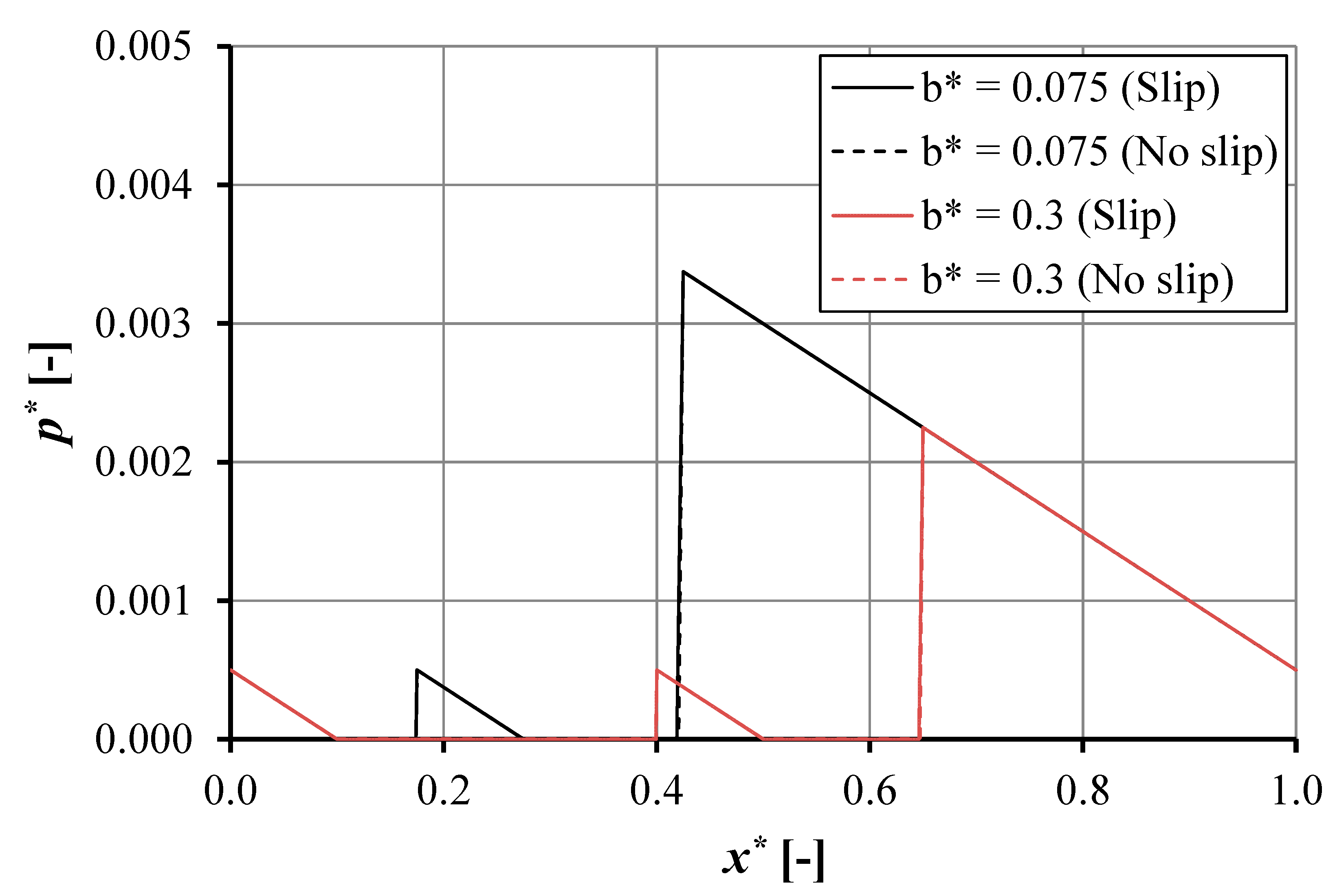
  • The maximum pressure and load support increase with reducing pocket length.
  • The slip condition in the pocket reduces the cavitation area both for the single- and double-pocket bearing. This slip effect is more pronounced when a high pocket depth is used.
  • The decrease in pocket length enhances the load support and reduces the cavitation area both for the slip and no-slip conditions irrespective of the pocket depth.
  • The main interesting finding is that the pocket depth reduces the cavitation area for both the single- and double-pocket bearing. However, the pocket depth has a more important influence in reducing the effect of cavitation in the case of the single pocket than in the case of the double pocket bearing.
For future research, the experiment will be the main concern to validate the developed lubrication model in terms of the cavitation area and the effect of hydrophobic coating layout.

Author Contributions

Conceptualization, M.M. and M.T.; methodology, J.J.; software, D.J.S.; validation, M.M., M.T. and J.J.; formal analysis, M.M.; investigation, M.T.; resources, J.J.; data curation, J.J.; writing—original draft preparation, M.M.; writing—review and editing, M.M.; visualization, M.T.; supervision, D.J.S.; project administration, M.M.; funding acquisition, J.J. All authors have read and agreed to the published version of the manuscript.

Funding

This research received no external funding.

Conflicts of Interest

The authors declare no conflict of interest.

Nomenclature

ainlet length
bfirst pocket width
Boslider length
clength between pockets
CLlength of cavitation area
CLblength of cavitation area first pocket
CLdlength of cavitation area second pocket
dsecond pocket width
eoutlet land length
hdheight of microtexture pocket (excluding film thickness)
hd1height of microtexture first pocket (excluding film thickness)
hd2height of microtexture second pocket (excluding film thickness)
hpfilm thickness in pocket
hp1film thickness in first pocket
hp2film thickness in second pocket
hominimum film thickness
P3pressure at C
P5pressure at E
patmatmospheric pressure
pcavcavitation pressure
Usliding velocity
wload support
qflow rate
xcoordinate in sliding direction
Xbnon-cavitated fraction of first pocket
Xdnon-cavitated fraction of second pocket
zcoordinate through film thickness
μlubricant dynamic viscosity
αs, αhslip coefficient at surface s (moving) and h (stationary)
Non-dimensional parameters
C L b = ( b X b ) / B o
C L d = ( d X d ) / B o
H D = h d / h o
H D 1 = h d 1 / h o
H D 2 = h d 2 / h o
p = p h o 2 / ( U μ B o )
x = x / B o
X b = X b / B o
X d = X d / B o
W = w h o 2 / ( U μ B o )

Appendix A

In this section, the details of the modified Reynolds equation are presented. Extending the work of Fowell et al. [24], the corresponding flow rate equation can be expressed as
q x = ( h 3 12 μ h 2 + 4 μ h ( α h + α s ) + 12 μ 2 α h α s h ( h + μ ( α h + α s ) ) p x ) + U 2 ( h 2 + 2 μ h α h h + μ ( α h + α s ) ) + h 2 μ p x h x μ h α h + 2 μ 2 α h α s h + μ ( α h + α s ) U h x μ α h h + μ ( α h + α s )
If slip is present only on the stationary surface (αs = 0 but αh ≠ 0), Equation (A1) will reduce to:
q x = ( h 3 12 μ p x h 2 + 4 μ h α h h ( h + μ α h ) ) + U 2 ( h 2 + 2 μ h α h ( h + μ α h ) )
For the first-order Reynolds equation, the flow rate is given as
q x = U 2 h 2 + 2 μ h α h h + μ α h h 3 12 μ h + 4 μ α h h + μ α h d p d x

Appendix A.1. Slip in Single Pocket

Cavitation in Single Pocket

Pressure Distribution

For the areas of the bearing including the parallel surfaces, the film thickness, h, is set constant, and therefore the pressure gradient must be linear (see Equation (A3)). Equation (A3) can be modified for each region of the bearing:
q A B = U 2 h o h o 3 12 μ ( P c a v P a t m a )
q B C = U 2 h p 2 + 2 μ h p α h h p + μ α h h p 3 12 μ h p + 4 μ α h h p + μ α h ( P 3 P c a v X b )
q C D = U 2 h o h o 3 12 μ ( P a t m P 3 c )
with the condition q A B = q B C = q C D based on volume conservation.
When q A B is set to be equal to q C D ,
U 2 h o h o 3 12 μ ( P c a v P a t m a ) = U 2 h o h o 3 12 μ ( P a t m P 3 c )
P 3 = P a t m + c a ( P a t m P c a v )
For the case of cavitation in the recess, P2 is assumed to be equal to Pcav, so q A B = q B C gives
U 2 h o h o 3 12 μ ( P c a v P a t m a ) = U 2 h p 2 + 2 μ h p α h h p + μ α h h p 3 12 μ h p + 4 μ α h h p + μ α h ( P 3 P c a v X b )
For
K p = μ α h h p + μ α h K p 1 = μ α h h p 1 + μ α h K p 2 = μ α h h p 2 + μ α h C p = h p + h p K p C p 1 = h p 1 + h p 1 K p 1 C p 2 = h p 2 + h p 2 K p 2 C p = h p 3 + 3 h p 3 K p C p 1 = h p 1 3 + 3 h p 1 3 K p 1 C p 2 = h p 2 3 + 3 h p 2 3 K p 2
Equation (A9) becomes
U 2 h o h o 3 12 μ ( P c a v P a t m a ) = U 2 C p C p 12 μ ( P 3 P c a v X b )
where
X b = C p ( P 3 P c a v ) 6 μ U ( C p h o ) h o 3 ( P a t m P c a v a )

Appendix A.2. Slip in Double Pockets

Cavitation in Double Pockets

Pressure Distribution

q A B = U 2 h o h o 3 12 μ ( P c a v P a t m a )
q B C = U 2 C p 1 C p 1 12 μ ( P 3 P c a v X b )
q C D = U 2 h o h o 3 12 μ ( P c a v P 3 c )
q D E = U 2 C p 2 C p 2 12 μ ( P 5 P c a v X d )
q E F = U 2 h o h o 3 12 μ ( P a t m P 5 e )
with the condition q A B = q B C = q C D = q D E = q E F based on volume conservation.
q A B is set to be equal to q B C
( P 3 P c a v X b ) = 6 μ U C p 1 ( C p 1 h o ) h o 3 C p 1 ( P c a v P a t m a )
q B C is set to be equal to q C D
( P 3 P c a v X b ) = 6 μ U C p 1 ( C p 1 h o ) h o 3 C p 1 ( P c a v P 3 c )
Substitution of Equation (A17) in Equation (A18) gives
P 3 = P c a v + c a ( P a t m P c a v )
X b = c C p 1 ( P a t m P c a v ) 6 μ U a ( C p 1 h o ) h o 3 ( P a t m P c a v )
q C D is set to be equal to q D E
( P 5 P c a v X d ) = 6 μ U C p 2 ( C p 2 h o ) h o 3 C p 2 ( P c a v P 3 c )
q D E is set to be equal to q E F
( P 5 P c a v X d ) = 6 μ U C p 2 ( C p 2 h o ) h o 3 C p 2 ( P a t m P 5 e )
Substitution of Equation (A21) in Equation (A22) gives
P 5 = P a t m + e a ( P a t m P c a v )
X d = ( a + e ) C p 2 ( P a t m P c a v ) 6 μ U a ( C p 2 h o ) h o 3 ( P a t m P c a v )

Appendix B

In this section, the validation of our model has been presented for the case of a single pocket. All dimensions and boundary conditions have been set to those used in the work of Fowell et al. [24]. The no-slip boundary condition is of particular interest by considering the cavitation. Figure A1 presents the load support prediction varying the inlet length for two values of pocket depth, hd = 2.5 and 7.5 µm. It can be observed that the predictions match well with the reference [24]. Our developed analytical lubrication model is very accurate with zero relative error in comparison with the analytical lubrication model of Fowell et al. [24].
Figure A1. The effect of inlet length on the load support. The profiles are calculated for ho = 1.0 × 10⁻⁶ m, b = 0.006 m, Bo = 0.02 m, α = 0.02 m2s/kg.
Lubricants 09 00003 g0a1

References

  1. Kalin, M.; Polajnar, M. The Effect of Wetting and Surface Energy on the Friction and Slip in Oil-Lubricated Contacts. Tribol. Lett. 2013, 52, 185–194. [Google Scholar] [CrossRef]
  2. Neto, C.; Evans, D.R.; Bonaccurso, E.; Butt, H.J.; Craig, V.S.J. Boundary Slip in Newtonian Liquids: A Review of Experimental Studies. Rep. Prog. Phys. 2005, 68, 2859–2897. [Google Scholar] [CrossRef]
  3. Hatzikiriakos, S.; Dealy, J. Wall Slip of Molten High Density Polyethylene. I. Sliding Plate Rheometer Studies. J. Rheol. 1991, 35, 497–523. [Google Scholar] [CrossRef]
  4. Etsion, I.; Halperin, G.; Brizmer, V.; Kligerman, Y. Experimental Investigation of Laser Surface Textured Parallel Thrust Bearing. Tribol. Lett. 2004, 17, 295–300. [Google Scholar] [CrossRef]
  5. Kovalchenko, A.; Ajayi, O.; Erdemir, A.; Fenske, G.; Etsion, I. The Effect of Laser Surface Texturing on Transitions in Lubrication Regimes During Unidirectional Sliding Contact. Tribol. Int. 2005, 38, 219–225. [Google Scholar] [CrossRef]
  6. Ryk, G.; Kligerman, Y.; Etsion, I. Experimental Investigation of Laser Surface Texturing for Reciprocating Automotive Components. STLE Tribol. Trans. 2002, 45, 444–449. [Google Scholar] [CrossRef]
  7. Etsion, I.; Halperin, G. A Laser Surface Textured Hydrostatic Mechanical Seal. STLE Tribol. Trans. 2002, 45, 430–434. [Google Scholar] [CrossRef]
  8. Wu, C.W.; Ma, G.J.; Zhou, P. Low Friction and High Load Support Capacity of Slider Bearing with a Mixed Slip Surface. ASME J. Tribol. 2006, 128, 904–907. [Google Scholar] [CrossRef]
  9. Tauviqirrahman, M.; Ismail, R.; Jamari, J.; Schipper, D.J. Computational Analysis of The Lubricated Sliding Contact with Artificial Slip Boundary. Int. J. Appl. Math. Stat. 2013, 5, 67–68. [Google Scholar]
  10. Choo, J.H.; Spikes, H.A.; Ratoi, M.; Glovnea, R.P.; Forrest, A. Friction Reduction in Low-Load Hydrodynamic Lubrication with a Hydrophobic Surface. Tribol. Int. 2007, 40, 154–159. [Google Scholar] [CrossRef]
  11. Choo, J.H.; Glovnea, R.P.; Forrest, A.K.; Spikes, H.A. A Low Friction Bearing Based on Liquid Slip at the Wall. ASME J. Tribol. 2007, 129, 611–620. [Google Scholar] [CrossRef]
  12. Bayada, G.; Meurisse, M.H. Impact of the Cavitation Model on the Theoretical Performance of Heterogeneous Slip/No-Slip Engineered Contacts in Hydrodynamic Conditions. Proc. Inst. Mech. Eng. Part J J. Eng. Tribol. 2009, 223, 371–381. [Google Scholar] [CrossRef]
  13. Xie, Z.-L.; Ta, N.; Rao, Z.-S. The Lubrication Performance of Water Lubricated Bearing Consideration of Wall Slip and Inertial Force. J. Hydrol. 2017, 29, 52–60. [Google Scholar] [CrossRef]
  14. Wu, C.W. Performance of Hydrodynamic Lubrication Journal Bearing with a Slippage Surface. Ind. Lubr. Tribol. 2008, 60, 293–298. [Google Scholar] [CrossRef]
  15. Wang, L.-L.; Lu, C.-H.; Wang, M. The Numerical Analysis of the Radial Sleeve Bearing with Combined Surface Slip. Tribol. Int. 2012, 47, 100–104. [Google Scholar] [CrossRef]
  16. Salant, R.F.; Fortier, A.E. Numerical Analysis of a Slider Bearing with a Heterogeneous Slip/No-Slip Surface. Tribol. Trans. 2004, 47, 328–334. [Google Scholar] [CrossRef]
  17. Guo, F.; Wong, P.L. Theoretical Prediction of Hydrodynamic Effect by Tailored Boundary Slippage. Proc. Inst. Mech. Eng. Part J J. Eng. Tribol. 2006, 220, 43–48. [Google Scholar] [CrossRef]
  18. Rao, T.V. Analysis of Single-Grooved Slider and Journal Bearing with Partial Slip Surface. ASME J. Tribol. 2010, 132, 014501–1–014501–7. [Google Scholar] [CrossRef]
  19. Tauviqirrahman, M.; Ismail, R.; Jamari, J.; Schipper, D.J. Combined Effect of Texturing and Boundary Slippage in Lubricated Sliding Contacts. Tribol. Int. 2013, 66, 274–281. [Google Scholar] [CrossRef] [Green Version]
  20. Tauviqirrahman, M.; Ismail, R.; Jamari, J.; Schipper, D.J. A Study of Surface Texturing and Boundary Slip on Improving the Load Support of Lubricated Parallel Sliding Contacts. Acta Mech. 2013, 224, 365–381. [Google Scholar] [CrossRef]
  21. Tauviqirrahman, M.; Muchammad, M.; Jamari, J.; Schipper, D.J. Numerical Study of the Load Carrying Capacity of Lubricated Parallel Sliding Textured Surfaces including Wall Slip. Tribol. Trans. 2013, 57, 134–145. [Google Scholar] [CrossRef]
  22. Tauviqirrahman, M.; Jamari, J.; Wibowo, B.S.; Fauzan, H.M.; Muchammad, M. Multiphase Computational Fluid Dynamics Analysis of Hydrodynamic Journal Bearing Under the Combined Influence of Texture and Slip. Lubricants 2019, 7, 97. [Google Scholar] [CrossRef] [Green Version]
  23. Kligerman, Y.; Etsion, I.; Shinkarenko, A. Improving Tribological Performance of Piston Rings by Partial Surface Texturing. ASME J. Tribol. 2005, 127, 632–638. [Google Scholar] [CrossRef]
  24. Fowell, M.; Olver, A.V.; Gosman, A.D.; Spikes, H.A.; Pegg, I. Entrainment and Inlet Suction: Two Mechanisms of Hydrodynamic Lubrication in Textured Bearings. ASME J. Tribol. 2007, 129, 337–347. [Google Scholar] [CrossRef]
  25. Pascovici, M.D.; Cicone, T.; Fillon, M.; Dobrica, M.B. Analytical Investigation of a Partially Textured Parallel Slider. Proc. Inst. Mech. Eng. Part J J. Eng. Tribol. 2009, 223, 151–158. [Google Scholar] [CrossRef]
  26. Rahmani, R.; Mirzaee, I.; Shirvani, A.; Shirvani, H. An Analytical Approach for Analysis and Optimization of Slider Bearings with Infinite Width Parallel Thrush. Tribol. Int. 2010, 43, 1551–1565. [Google Scholar] [CrossRef] [Green Version]
  27. Arghir, M.; Roucou, N.; Helene, M.; Frene, J. Theoretical Analysis of the Incompressible Laminar Flow in a Macro-Roughness Cell. ASME J. Tribol. 2003, 125, 309–318. [Google Scholar] [CrossRef]
  28. Caramia, G.; Carbone, G.; Palma, P.D. Hydrodynamic Lubrication of Micro-Textured Surfaces: Two Dimensional CFD-Analysis. Tribol. Int. 2015, 88, 62–169. [Google Scholar] [CrossRef]
  29. Sahlin, F.; Glavatskih, S.B.; Almqvist, T.; Larsson, R. Two-Dimensional CFD-Analysis of Micro-Patterned Surfaces in Hydrodynamic Lubrication. ASME J. Tribol. 2005, 127, 96–102. [Google Scholar] [CrossRef]
  30. Brajdic-Mitidieri, P.; Gosman, A.D.; Loannides, E.; Spikes, H.A. CFD Analysis of a Low Friction Pocketed Pad Bearing. ASME J. Tribol. 2005, 127, 803–812. [Google Scholar] [CrossRef]
  31. Dobrica, M.B.; Fillon, M. About the Validity of Reynolds Equation and Inertia Effects in Textured Sliders of Infinite Width. Proc. Inst. Mech. Eng. Part J J. Eng. Tribol. 2009, 223, 69–78. [Google Scholar] [CrossRef]
  32. Han, J.; Fang, L.; Sun, J.; Ge, S. Hydrodynamic Lubrication of Microdimple Textured Surface Using Three-Dimensional CFD. Tribol. Trans. 2010, 53, 860–870. [Google Scholar] [CrossRef]
  33. Gropper, D.; Wang, L.; Harvey, T.J. Hydrodynamic Lubrication of Textured Surfaces: A Review of Modeling Techniques and Key Findings. Tribol. Int. 2016, 94, 509–529. [Google Scholar] [CrossRef] [Green Version]
  34. Sudeep, U.; Tandon, N.; Pandey, R.K. Performance of Lubricated Rolling/ Sliding Concentrated Contact with Surface Textures: A Review. ASME J. Tribol. 2015, 137, 031501–1. [Google Scholar] [CrossRef]
  35. Brito, F.P.; Miranda, A.S.; Fillon, M. Analysis of the Effect of Grooves in Single and Twin Axial Groove Journal Bearings Under Varying Load Direction. Tribol. Int. 2016, 103, 609–619. [Google Scholar] [CrossRef] [Green Version]
  36. Shi, X.; Ni, T. Effect of Groove Textures on Fully Lubricated Sliding with Cavitation. Tribol. Int. 2011, 44, 2022–2028. [Google Scholar] [CrossRef]
  37. Gherca, A.; Fatu, A.; Hajjam, M.; Maspeyrot, P. Influence of Surface Texturing on the Hydrodynamic Performance of a Thrust Bearing Operating in Steady-State and Transient Lubrication Regime. Tribol. Int. 2016, 102, 305–318. [Google Scholar] [CrossRef]
  38. Mao, Y.; Zeng, L.; Lu, Y. Modeling and Optimization of Cavitation on A Textured Cylinder Surface Coupled with the Wedge Effect. Tribol. Int. 2016, 104, 212–224. [Google Scholar] [CrossRef]
  39. Galda, L.; Sep, J.; Prucnal, S. The Effect of Dimple Geometri in Sliding Surface on the Tribological Properties Under Starved Lubrication. Tribol. Int. 2016, 99, 77–84. [Google Scholar] [CrossRef]
  40. Kasem, H.; Stav, O.; Grützmacher, P.; Gachot, C. Effect of Low Depth Surface Texturing on Friction Reduction in Lubricated Sliding Contact. Lubricants 2018, 6, 62. [Google Scholar] [CrossRef] [Green Version]
  41. Fortier, A.E.; Salant, R.F. Numerical Analysis of a Journal Bearing with a Heterogeneous Slip/ No-Slip Surface. ASME J. Tribol. 2005, 127, 820–825. [Google Scholar] [CrossRef] [Green Version]
  42. Wang, L.; Lu, C. Numerical Analysis of Spiral Oil Wedge Sleeve Bearing Including Cavitation and Wall Slip Effect. Lubr. Sci. 2015, 27, 193–207. [Google Scholar] [CrossRef]
  43. Ma, G.J.; Wu, C.W.; Zhou, P. Hydrodynamic of Slip Wedge and Optimization of Surface Slip Property. Sci. China Phys. Mech. 2007, 50, 321–330. [Google Scholar] [CrossRef]
  44. Ma, G.J.; Wu, C.W.; Zhou, P. Influence of Wall Slip on the Hydrodynamic Behavior of a Two-Dimensional Slider Bearing. Acta Mech. Sin. 2007, 23, 655–666. [Google Scholar] [CrossRef]
  45. Aurelian, F.; Patrick, M.; Mohamed, H. Wall Slip Effects in (Elasto) Hydrodynamic Journal Bearing. Tribol. Int. 2011, 44, 868–877. [Google Scholar] [CrossRef]
  46. Ma, G.J.; Wu, C.W.; Zhou, P. Wall Slip and Hydrodynamics of Two-Dimensional Journal Bearing. Tribol. Int. 2007, 40, 1056–1066. [Google Scholar] [CrossRef]
  47. Ma, X.; Meng, X.; Wang, Y.; Peng, X. Suction Effect of Cavitation in the Reverse-Spiral-Grooved Mechanical Face Seals. Tribol. Int. 2019, 132, 142–153. [Google Scholar] [CrossRef]
  48. Biancofiorea, L.; Giacopinib, M.; Dinic, D. Interplay Between Wall Slip and Cavitation: A Complementary Variable Approach. Tribol. Int. 2019, 137, 324–339. [Google Scholar] [CrossRef]
  49. Muchammad, M.; Tauviqirrahman, M.; Pratomo, A.W.; Jamari, J.; Schipper, D.J. Theoretical Investigation of Boundary Slip on the Hydrodynamic Lubrication Performance in Pocketed Bearings Including Cavitation. Int. J. Surf. Sci. Eng. 2017, 11, 100–117. [Google Scholar] [CrossRef]
Figure 1. Schematic of the parallel sliding single-pocket bearing considering cavitation for the case: (a) Slip condition and (b) No-slip condition. Note: The meaning of each parameter is shown in Table 1 and nomenclature.
Lubricants 09 00003 g001
Figure 2. Schematic of the parallel sliding double-pocket bearing considering cavitation for the case: (a) Slip condition and (b) No-slip condition. Note: The meaning of each parameter is shown in Table 2 and nomenclature.
Lubricants 09 00003 g002
Figure 3. The pressure distribution p* as a function of coordinate x* in the sliding direction for the pocketed bearing for ho = 1 × 10⁻⁶ m, a = 0.002 m, b = 0.0015 m, e = 0.0165 m, Bo = 0.02 m, and α = 0.02 m2s/kg for the case.
Lubricants 09 00003 g003
Figure 4. The cavitation area as a function of pocket depth and sliding direction of the pocketed bearing for ho = 1 × 10⁻⁶ m, a = 0.002 m, b = 0.0015 m, e = 0.0165 m, Bo = 0.02 m, and α = 0.02 m2s/kg.
Lubricants 09 00003 g004
Figure 5. The pressure distribution p* as a function of coordinate x* in the sliding direction for the pocketed bearing for ho = 1 × 10⁻⁶ m, a = 0.002 m, b = 0.006 m, e = 0.012 m, Bo = 0.02 m, and α = 0.02 m2s/kg for the case.
Lubricants 09 00003 g005
Figure 6. The cavitation area as a function of pocket depth and sliding direction of the pocketed bearing for ho = 1 × 10⁻⁶ m, a = 0.002 m, b = 0.006 m, e = 0.012 m, Bo = 0.02 m, and α = 0.02 m2s/kg.
Lubricants 09 00003 g006
Figure 7. The pressure distribution as a function of coordinate in sliding direction for the single pocketed bearing for hd = 1 × 10⁻⁶ m, ho = 1 × 10⁻⁶ m, a = 0.002 m, Bo = 0.02 m, and α = 0.02 m2s/kg.
Lubricants 09 00003 g007
Figure 8. The cavitation area as a function of pocket depth and sliding direction of the single-pocketed bearing for ho = 1 × 10⁻⁶ m, a = 0.002 m, Bo = 0.02 m, and α = 0.02 m2s/kg.
Lubricants 09 00003 g008
Figure 9. The no-cavitation area as a function of pocket depth sliding direction of the single pocketed bearing for ho = 1 × 10⁻⁶ m, a = 0.002 m, Bo = 0.02 m, and α = 0.02 m2s/kg.
Lubricants 09 00003 g009
Figure 10. The pressure distribution as a function of coordinate in sliding direction for the double-pocketed bearing for hd2 = 1 × 10⁻⁶ m, ho = 1 × 10⁻⁶ m, a = 0.002 m, b = 0.0015 m, c = 0.002 m, d = 0.003 m, e = 0.0115 m, Bo = 0.02 m, and α = 0.02 m2s/kg.
Lubricants 09 00003 g010
Figure 11. The cavitation area as a function of the pocket depth of the first pocketed bearing for hd2 = 1 × 10⁻⁶ m, ho = 1 × 10⁻⁶ m, a = 0.002 m, b = 0.0015 m, c = 0.002 m, d = 0.003 m, e = 0.0115 m, Bo = 0.02 m, and α = 0.02 m2s/kg.
Lubricants 09 00003 g011
Figure 12. The pressure distribution as a function of coordinate in sliding direction for the pocketed bearing for hd2 = 1 × 10⁻⁶ m, ho = 1 × 10⁻⁶ m, a = 0.002 m, b = 0.006 m, c = 0.002 m, d = 0.003 m, e = 0.007 m, Bo = 0.02 m, and α = 0.02 m2s/kg.
Lubricants 09 00003 g012
Figure 13. The cavitation area in the first pocket as a function of pocket depth of the first pocketed bearing for hd2 = 1 × 10⁻⁶ m, ho = 1 × 10⁻⁶ m, a = 0.002 m, b = 0.006 m, c = 0.002 m, d = 0.003 m, e = 0.007 m, Bo = 0.02 m, and α = 0.02 m2s/kg.
Lubricants 09 00003 g013
Figure 14. The pressure distribution as a function of coordinate in sliding direction for the pocketed bearing for hd1 = 1 × 10⁻⁶ m, hd2 = 1 × 10⁻⁶ m, ho = 1 × 10⁻⁶ m, a = 0.002 m, c = 0.002 m, d = 0.003 m, Bo = 0.02 m, and α = 0.02 m2s/kg.
Lubricants 09 00003 g014
Figure 15. The no-cavitation area in the first pocket as a function of pocket depth of the double pocketed bearing for hd1 = 1 × 10⁻⁶ m, hd2 = 1 × 10⁻⁶ m, ho = 1 × 10⁻⁶ m, a = 0.002 m, c = 0.002 m, d = 0.003 m, Bo = 0.02 m, and α = 0.02 m2s/kg.
Lubricants 09 00003 g015
Figure 16. The no-cavitation area as a function of pocket depth of the single- and double-pocketed bearing for hd1 = 1 × 10⁻⁶ m, hd2 = 1 × 10⁻⁶ m, ho = 1 × 10⁻⁶ m, a = 0.002 m, c = 0.002 m, d = 0.003 m, Bo = 0.02 m, and α = 0.02 m2s/kg.
Lubricants 09 00003 g016
Table 1. Characteristics of a single-pocket bearing.
ParameterData SettingUnit
Pocket depth, hd0.1; 0.5; 1.0; and 2.0µm
Land film thickness, ho1 × 10−6m
Total length, Bo0.02m
Inlet length, a0.002m
Pocket length, b0.0015; 0.006m
Exit land length, e0.0165; 0.012m
Atmospheric pressure, Patm100kPa
Cavitation pressure, Pcav0kPa
Sliding velocity, U1m/s
Slip coefficient, α0.02m2s/kg
Lubricant viscosity, µ0.01Pa·s
Table 2. Dimensionless load support in single-pocket bearing with b = 0.0015 m.
HDDimensionless Load Support
W* (10−3)
Change in Load Support (%)
SlipNo-Slip
0.11.6471.663−0.97
0.51.6511.6510
1.01.6581.6530.30
2.01.6771.6630.84
Table 3. Dimensionless load support in single-pocket bearing with b = 0.006 m.
HDDimensionless Load Support
W* (10−3)
Change in Load Support (%)
SlipNo-Slip
0.10.7300.739−1.23
0.50.7320.7320
1.00.7360.7330.41
2.00.7470.7391.07
Table 4. Characteristics of a double-pocket bearing.
ParameterData SettingUnit
First pocket depth, hd10.1; 0.5; 1.0; and 2.0µm
Land film thickness, ho1 × 10−6m
Total length, Bo0.02m
Inlet length, a0.002m
First pocket length, b0.0015; 0.006m
Length between pocket, c0.002m
Second pocket length, d0.003m
Exit land length, e0.0115; 0.007m
Atmospheric pressure, Patm100kPa
Cavitation pressure, Pcav0kPa
Sliding velocity, U1m/s
Slip coefficient, α0.02m2s/kg
Lubricant viscosity, µ0.01Pa·s
Table 5. Dimensionless load support of double-pocket bearing with b = 0.0015 m.
HD1Dimensionless Load Support
W* (10−3)
Change in Load Support (%)
SlipNo-Slip
0.10.67420.67190.35
0.50.67430.67180.37
1.00.67440.67180.39
2.00.67460.67190.40
Table 6. Dimensionless load support of double-pocket bearing with b = 0.006 m.
HD1Dimensionless Load Support
W* (10−3)
Change in Load Support (%)
SlipNo-Slip
0.10.03580.03492.60
0.50.03590.03483.12
1.00.03600.03483.27
2.00.03620.03493.56
Publisher’s Note: MDPI stays neutral with regard to jurisdictional claims in published maps and institutional affiliations.

