Review

A Practical Approach to Gear Design and Lubrication: A Review

by
Dario Croccolo
1,
Massimiliano De Agostinis
1,
Giorgio Olmi
1 and
Nicolò Vincenzi
2,*
1
Department of Industrial Engineering (DIN), University of Bologna, Viale del Risorgimento, 2, 40136 Bologna, Italy
2
GIULIANI, A Bucci Automations S.p.A. Division, Via Granarolo 167, 48018 Faenza, Italy
*
Author to whom correspondence should be addressed.
Lubricants 2020, 8(9), 84; https://doi.org/10.3390/lubricants8090084
Submission received: 9 June 2020 / Revised: 10 August 2020 / Accepted: 14 August 2020 / Published: 20 August 2020

Abstract

:
The modern design of mechanical parts, such as gears, goes through the continuous demand for a high level of efficiency and reliability, as well as an increased load carrying capacity and endurance life. The aim of the present paper was to perform a review and to collect practical examples in order to provide interesting tips and guidelines for gear design, including both its dimensioning and its lubrication. From this point of view, this paper is particularly novel, as it is a full-comprehensive collection of all the tools supporting gear design. Several practical aspects have been taken into account, including the definition of the right profile shifting, the selection of a proper lubricant, and the definition of the quality grade and of the tolerances needed to obtain the correct backlash. Finally, a numerical example is provided, addressing the research of the best solution to fit a given space, while maximizing the transmittable torque over weight ratio for two mating spur gears.

1. Introduction

The modern design of mechanical parts, such as gears, goes through the continuous demand for a high level of efficiency and reliability, as well as an increased load carrying capacity and endurance life. At the same time, the concepts of “robust design” and “optimization” involve nowadays the need for a very high-power density (involving smaller size, lower weight, lower noise and vibrations), as well as longer service intervals [1,2]. Finally, the aspects related to sustainability (analysis of the impact on the environment) and low-cost design are also commonly regarded as driving forces in the development of modern products. Within this framework, gear design must address, for example, low consumption of lubrication oil, keeping hydraulic losses as low as possible [3]. Oil/air mist (micro-fog) may be used for bearing and gear lubrication, especially in combination with compact design approaches, for instance in the field of machine tool industry. Regarding this point, an applicative example is shown in Figure 1. A continuous lubrication can be achieved by this strategy, involving very low oil quantities with consequent consumption sharp reduction. Depending on the application, the type of oil, whose main feature is viscosity, can be selected between ISO VG32 (high speed) and ISO VG 68 (high load). The oil flow, Q [mm3/h], being needed for lubrication by micro-fog, can be evaluated by Equation (1), where Dm is the mean bearing diameter or the gear pitch diameter.
Q = 1.2 · D m t o 1.3 · D m
With reference to the case study in Figure 1, a MOBIL DTE LIGHT 32 oil and a centralized unit, having the capability of providing (by a suitable amount of nozzles) 5 to 30 mm3/cycle, were selected. The required oil flow, Q [mm3/h], depending on the number and size of bearings and gears, was estimated as Q = 3000 mm3/h. The nozzles were set at 15 mm3/cycle; therefore, the number of cycles requested to the nozzles, to provide the required flow was set to 200 cycles per hour. The air pressure may be set for this application between 0.3 and 2.0 bar, depending on the dimension of the components (the bigger components, the lower the pressure level).
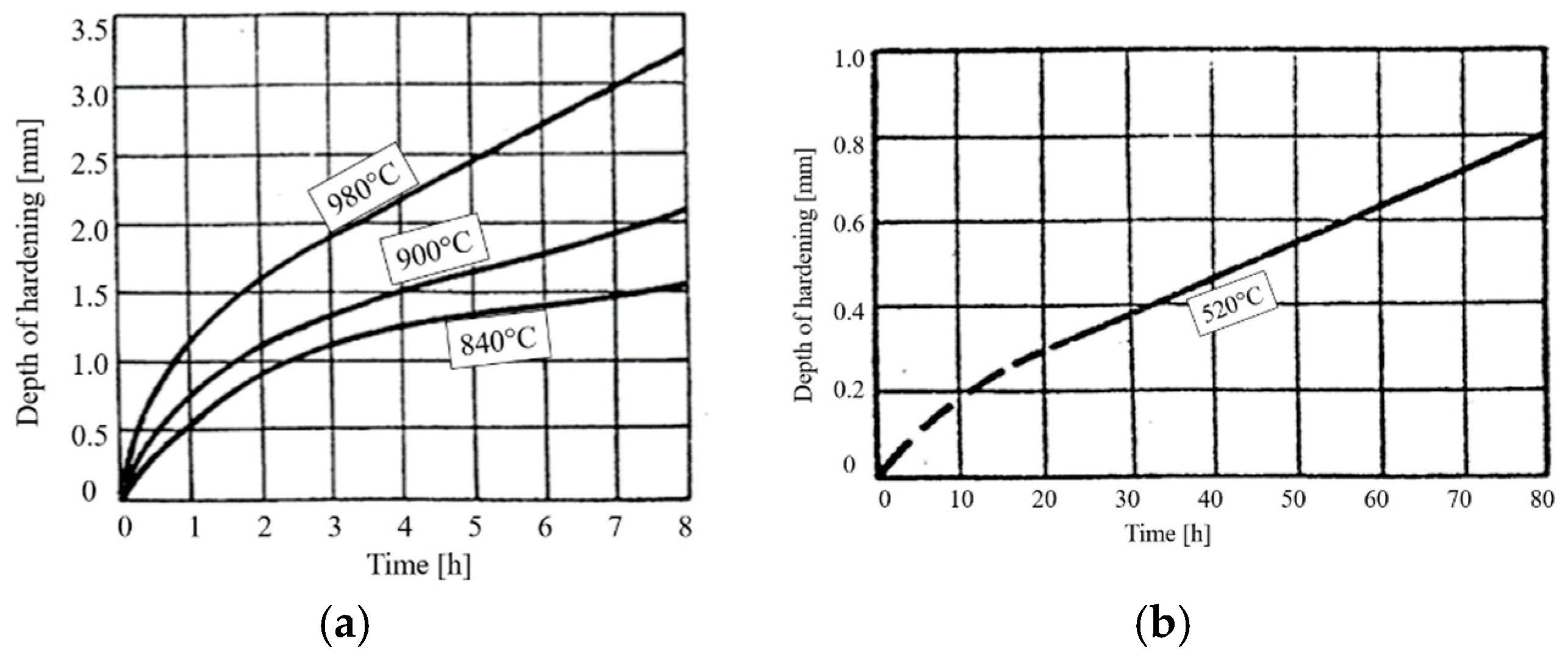
As for lubrication, the selection of the material and its thermal treatment is the other key choice, to increase the power density: case hardened and nitrided gears are the two most common alternative options [4,5,6,7,8]. Both treatments warrant improved contact (and bending) fatigue performance. The main differences between the two treatments, from the point of view of their application, are a consequence of the manufacturing cycle and of the distortions arising from the thermo-chemical process. The high temperature of the carburizing process induces larger distortions that entail subsequent machining, being usually conducted by grinding, and the consequent amount of allowance to be removed. The lower temperature of nitriding treatments allows for finishing process (milling or grinding) being completed before heat treatment, taking advantage of lower distortions. However, nitriding has the drawback of generally requiring a longer treatment duration. Moreover, it produces lower case depths, according to Figure 2.
In the past 20 years, gear design has been approached from these two points of view:
  • increasing power density as much as possible, which has led to gears with asymmetric teeth, according to Reference [9,10]; and
  • speeding-up gear production time, which has led to additively manufactured gears [11].
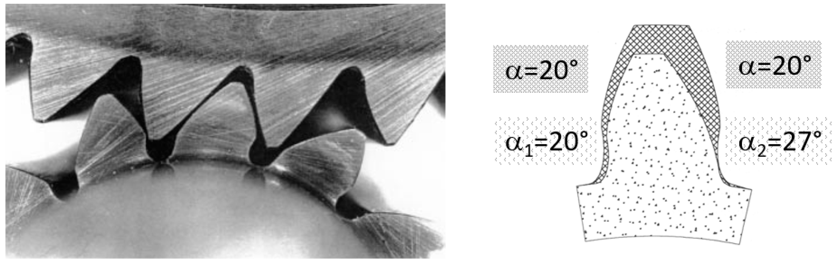
As for asymmetric gears, today, a modern 5-axes Computerized Numerical Control (CNC) machine makes it possible to cut a tooth, where the drive side is differently shaped, if compared to the coast side (see Figure 3). The effect of this tooth profile alteration can be twofold:
  • Keeping the same drive side pressure angle (i.e., 20°), while increasing the coast side pressure angle (i.e., 25° to 35°), it is possible to increase tooth bending strength or to obtain the same strength for a thinner tooth head. The benefit arising from this improved shape can be expressed as a function of the difference between the drive and coast pressure angles, according to reference [12]. However, this design does not affect the actual load capacity that is limited by high contact stresses, as no change in drive side pressure angle occurs.
  • Increasing drive side pressure angle, according to Reference [9], it is possible to drop down the stresses (due to both bending and contact) and, furthermore, to also reduce the vibrational level.
With regard to additively manufactured gears, a recent study [11] highlighted the performance of gears produced by Selective Laser Melting: the retrieved mechanical strength is generally lower than that of wrought material gears, especially under fatigue [13], mainly due to the induced porosities and residual stresses, but the advantage in terms of saved production time is not negligible. In addition, it is worth mentioning that forged bi-metal gears can be fabricated today [14,15].
This review paper aimed at steering the designer through gear development, based on industrial specifications, including, on one hand, its design, dimensioning, and final drawing, and, on the other hand, its most suitable lubrication. Regarding the first point, this paper deals with a collection of formulas, tables and graphs taken from standards and scientific and technical studies in the literature. These formulas have sometimes been revisited, to account for gear design (instead of just verification) purposes. As for the second point, the guidelines for lubrication this paper provides are based on the available tools in the technical literature and are strictly related to the main features of the industrial application to be developed. Issues of novelty arise from the lack of scientific or technical review studies, addressing this topic and providing what can be regarded as a full-comprehensive collection of the aforementioned tools that are expected to significantly support the design task.

2. Practical Design of Gears

The structural assessment of mating gears can be carried out by well-known standards, such as ISO [16] or American Gear Manufacturers Association, AGMA [17], thus assessing gear load capacity against both bending stresses and pitting (contact) stresses. The verification is based on the calculation of several factors that affect the nominal stresses, as well as the allowable stresses. The stress analysis may also be deepened further determining local stresses for fatigue life prediction, according to Reference [18,19,20,
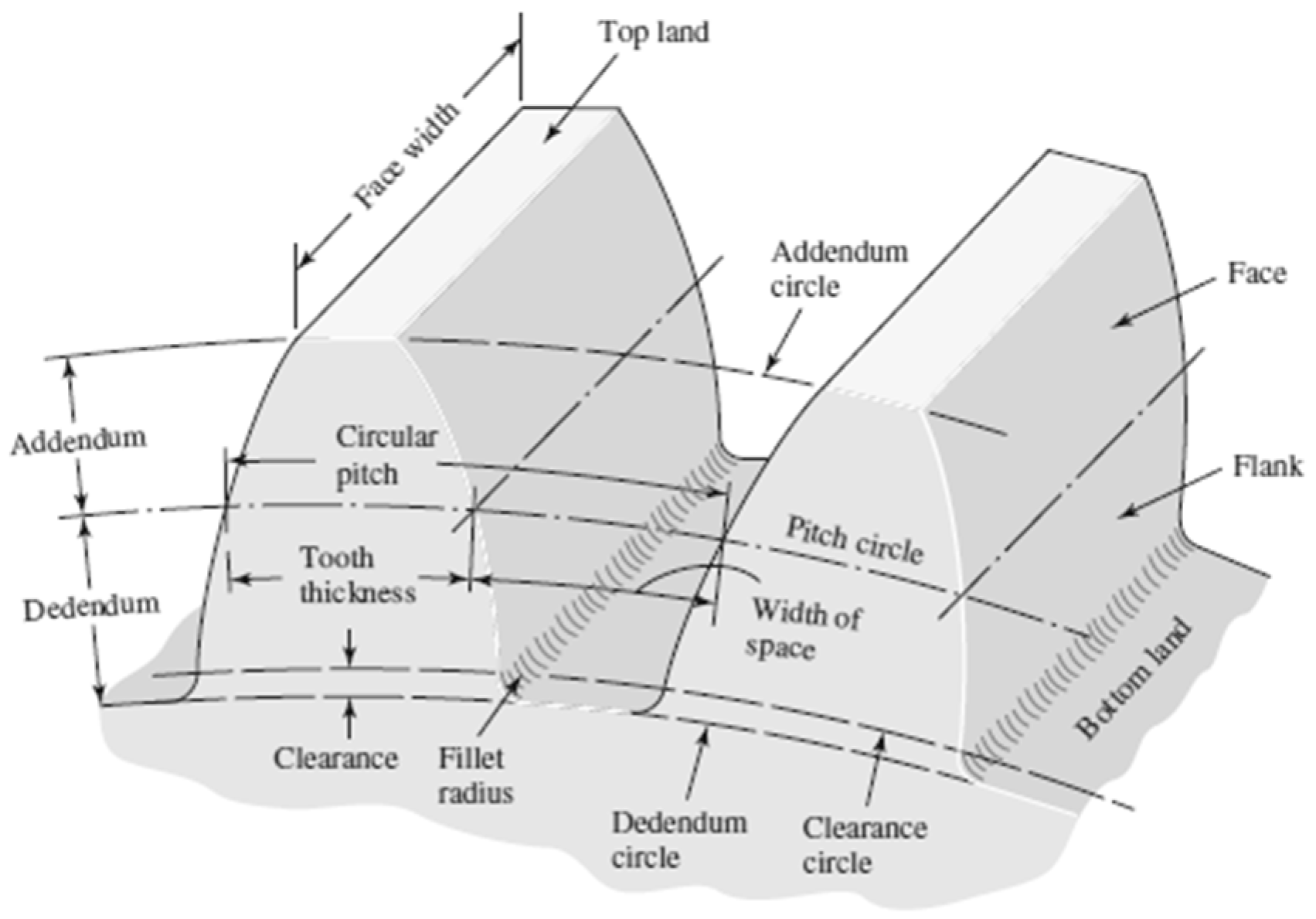
21]. However, these procedures require the full definition of gear geometry: In other words, verification and accurate structural assessment are possible, but gear design, starting from the white paper, is almost impossible, unless an iterative methodology is exploited. In particular, a simplified (practical) procedure must be applied, in order to coarsely design the transmission, thus defining all the starting parameters to allow for verification. This practical procedure must also account for the possible need for profile shifting (both with or without center distance variation): For this purpose, optimal values for the profile shifting coefficient should be made available to the designer. The approach in the present paper is based on the Nomenclature in the Appendix A, also according to Figure 4:
In order to warrant motion regularity, the (transverse) contact ratio must be εα > [1.25 to 1.4].
An example of calculation for εα is reported in Table 1.
For powertrain design, the initially available data, to be regarded as specifications, are usually the input/output torque Mt [Nm], the input/output rotational speed n [rpm] (and therefore the transmission ratio τ), and the space available for the application, namely the theoretical wheelbase I [mm]. It is first suggested to evaluate (in a very fast and approximated way) a starting module m, based on the following Equation (2):
m Y · M t · 1000 λ · σ a m m 3 .
In Equation (2), λ can be chosen by the designer in the following ranges (practical value λ = 8 to 12):
  • 6 < λ < 10 for gearbox applications (characterized by the need for gear shifting) or for gears mounted on cantilever shaft;
  • 15 < λ < 25 for gears on rigid supports;
  • 25 < λ < 45 for gears on very rigid supports with rigid shaft; and Y (derived from the Lewis coefficient) can be considered equal to:
  • 0.8 for z < 20;
  • 0.6 for 20 < z < 40;
  • 0.4 for z > 40.
The allowable stress can be assumed as σall~150 MPa in the case of gear made of steel. The designer is then expected to select the first available module, according to the ones in ISO 54 [24]. Subsequently, based on the starting module, it is possible to address gear design, following the steps below (input data: I, τ).
The number of teeth z1,2 can be selected as (Equation (3)):
z 1 = 2 · I m · ( 1 + 1 τ ) ; z 2 = z 1 τ .
The tooth can be designed according to modular ISO 53 [23] proportion (a = m; 
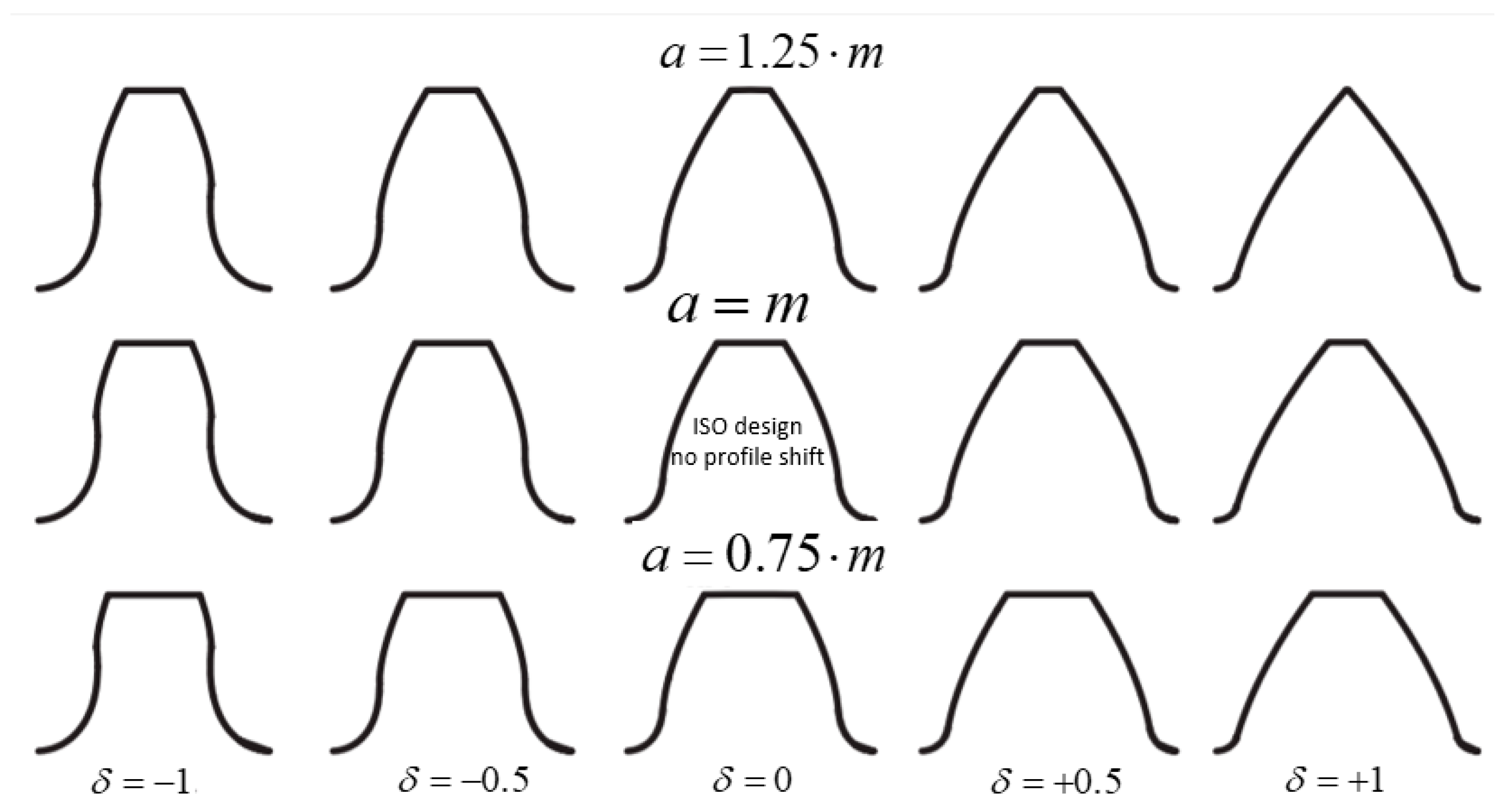
d = 1.25 m) or to stub proportion (a = 0.8 m; d = m). Stub proportioning is suitable for highly stressed gears (generally operating under high torque, low speed) because the tooth is made stiffer. On the other hand, it must be remarked that stub design is affected by a reduced contact ratio with respect to the modular proportioning. The designer has to then calculate the contact ratio εα and verify the condition for motion regularity (εα > [1.25 to 1.4]), as well as the further condition regarding the minimum number of teeth threshold, to avoid under-cut (Equation (4)) without profile shifting:
z 1 _ min = 2 · a m · s e n 2 ϑ ;   z 1 _ min _ I S O = 18 ;   z 1 _ min _ S T U B = 14
The following step is estimating the needed profile shifting [25]. This strategy (generally regarded as positive profile shifting) can be used to obtain different advantages, such as:
  • avoiding under-cut;
  • improving the response of the pinion gear against bending and pitting; and
  • modifying the wheelbase (working wheelbase different from theoretical wheelbase).
The working wheelbase Ii [mm] is usually selected by the designer and, as further steps, the following items may be calculated: (i) the working pressure angle ϑi [°]; (ii) the addition of profile shifting x1 + x2 [mm]; or (iii) their dimensionless coefficients δ1 + δ2 by Equation (5):
{ cos ( ϑ i ) = I · cos ( ϑ ) I i x 1 + x 2 = z 1 + z 2 2 · tan ( ϑ ) · ( i n v ( ϑ i ) i n v ( ϑ ) ) · m ; δ 1 + δ 2 = x 1 + x 2 m .
The designer has then to split the sum of profile shifting coefficients δ1 + δ2 into two terms, to be applied to the pinion (δ1) and the wheel (δ2), respectively. For this purpose, the designer may take advantage of Equation (6), based on the suggestions of Reference [26,27,28]: In particular, for a fast selection (starting point), Reference [26], highlights that the proposed Equation (6) allows, with a certain approximation, the same specific sliding at the tooth base for the pinion and the gear.
{ δ 1 δ 1 + δ 2 2 · ( z 1 100 + τ τ · z 1 100 ) + 0.5 · ( 1 z 1 100 ) · ( 1 τ ) δ 2 = ( δ 1 + δ 2 ) δ 1 .
It is then possible to determine the modified tooth shape and, in particular:
  • the coefficient k, which, in turn, makes it possible to evaluate the required reduction of addendum (tooth head cutting). To ensure the same clearance (see Figure 4) with the modified working geometry (Equation (7)):
    k = | I i I ( x 1 + x 2 ) m | ;
  • the working addendum ai and dedendum di [mm] (Equation (8)):
    { a i _ 1 , 2 = a + x 1 , 2 k · m d i _ 1 , 2 = d x 1 , 2 ;
  • the actual minimum number of teeth, considering profile shifting. to avoid under-cut (Equation (9)):
    z i _ 1 _ m i n = 2 · ( a x 1 ) m · s i n 2 ϑ ;
  • the tooth thickness si_1,2 [mm], evaluated at the reference diameter (Equation (10)):
    s i _ 1 , 2 = m · cos ( ϑ ) cos ( ϑ i ) · [ π 2 + 2 · δ 1 , 2 · tan ( ϑ ) z 1 , 2 · ( i n v ( ϑ i ) i n v ( ϑ ) ) ] .
An example of tooth shape evolution, as a function of profile shifting coefficient is shown in Figure 5.
Once the geometrical parameters have been defined, it is possible to proceed with gear calculation against tooth bending and contact stresses. This procedure leads to the final accurate estimation of the gear module. The maximum stress must be lower than the allowable one: the resistance conditions for bending and pitting are reported in Equations (11) and (12), respectively (see Reference [28]):
σ max _ b e n d i n g = ( 2000 · M t D ) · q · L b · m · ε · η d σ lim _ b e n d i n g ,
{ p max _ p i t t i n g = f · ( 2000 · M t D ) · L b · m · ( 1 z 1 + 1 z 2 ) η d · η E p lim _ p i t t i n g = 2.5 · H d n · h 6 f = 0.417 2 · 2 1 2 · ( 1 E 1 + 1 E 2 ) · s e n ( ϑ ) · cos ( ϑ ) .
With reference to these formulas, the following parameters need to be considered, according to Reference [28]:
  • q is the tooth form factor (with load applied at the outer point of single tooth pair contact): it takes tooth shape into account (Table 2);
  • L is the dynamic factor, which accounts for load increments due to dynamic effects upon load application (Table 3);
  • ε is the factor considering load sharing between more than one tooth pair (Table 4);
  • ƞd is the factor that takes speed effect into account (Table 5);
  • ƞE is the factor depending on lubrication condition (Table 6). For high speed gears (v > 10 m/s) oil viscosity can be selected between 46 cst and 100 cst (increasing with the applied load); for highly loaded gears (usually not at high speed), oil viscosity is within 150 cst and 680 cst (increasing with load); for v < 2 m/s, even permanent grease lubrication may be chosen. Wear resistance generally increases with viscosity; however, the higher viscosity, the higher power losses and temperature increase (for service temperature greater than 60 °C, it is suggested to cool the oil);
  • the parameter f [N0.5/mm], for steel on steel gears (Young’s modulus E = 200 GPa) and ϑ = 20°, takes the value of 473 N0.5/mm; when profile shifting is applied, f must be calculated with ϑi instead of ϑ (with positive profile shift, ϑi > ϑ; therefore, it is possible to achieve benefits in terms of maximum contact stress value reduction).
As for the expected working hours h, reference values can be considered as:
  • h = 40,000 to 150,000 for applications running 24 h per day (like turbines or important production machines);
  • h = 20,000 to 30,000 for applications running 8 h per day (standard production machines);
  • h = 5000 to 15,000 for applications running some hours per day (automotive or lifting devices);
  • h = 500 to 1500 for limited running;
Finally, allowable stresses may be worked out from the values reported in Table 7: Bending strength also takes stress concentration at tooth root into account for a standard 0.25·m fillet radius (Figure 4).
In order to correctly determine the most suitable module value (after its initial rough estimation, based on the raw formula of Equation (2)), the inequalities in Equations (11) and (12) have been inverted, according to Equations (13) and (14), so that module thresholds are yielded as follows:
m b e n d i n g 2000 · M t _ 1 , 2 · q 1 , 2 · L z 1 , 2 · λ · ε 1 , 2 · η d _ 1 , 2 · σ lim _ b e n d i n g _ 1 , 2 3 ,
m p i t t i n g 0.69 · f 1 , 2 2 · L · M t _ 1 , 2 · ( 1 z 1 + 1 z 2 ) η d _ 1 , 2 · η E · H d _ 1 , 2 2 · λ · z 1 , 2 3 · n 1 , 2 · h 9 .
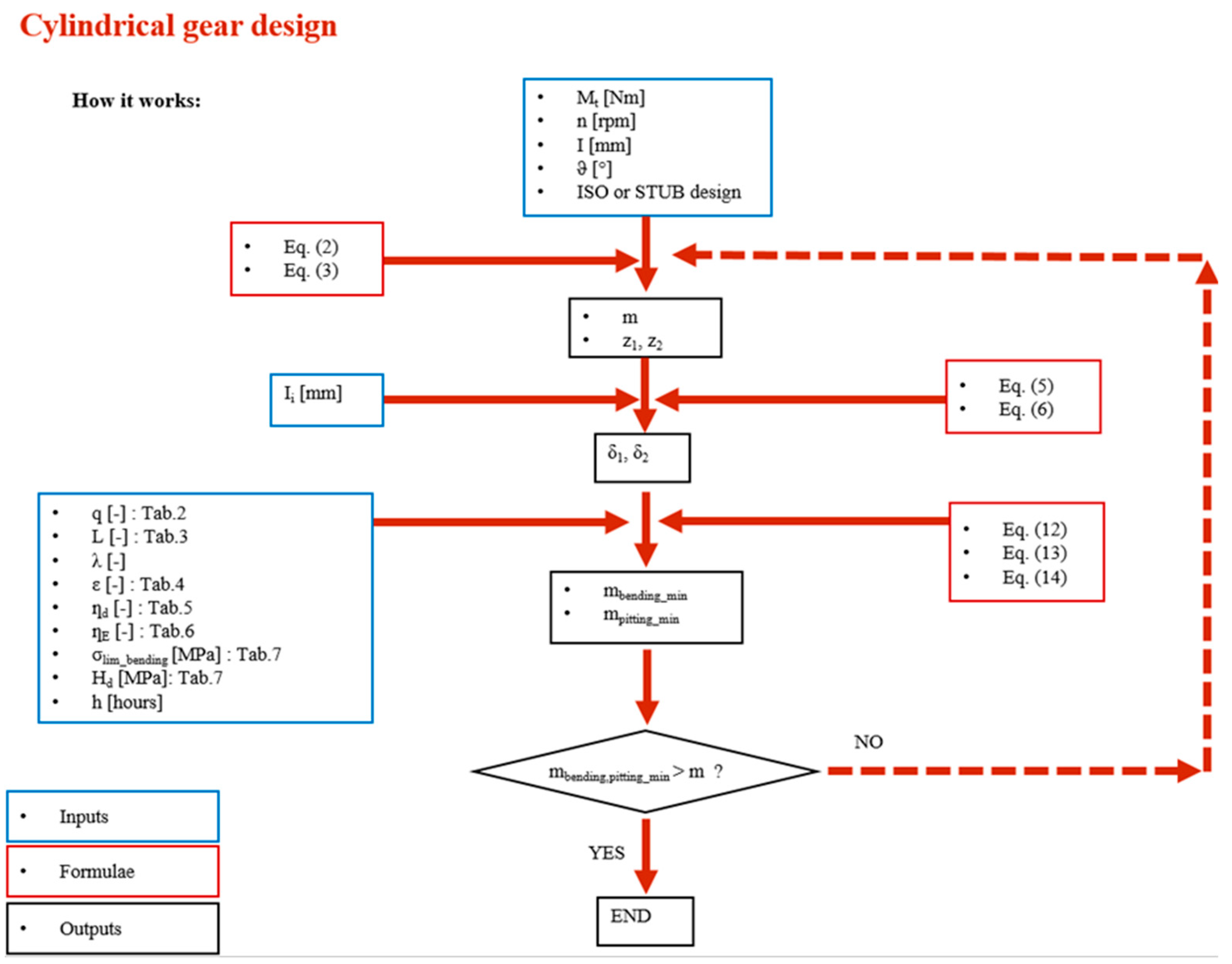
All the proposed steps are particularly suitable for automatic computation by electronic datasheets and may also be used for optimization purposes, as in the numerical example in Section 5. The described procedure is also available for more sophisticated optimization strategies, for instance by Genetic Algorithms, as proposed in Reference [29]. For the sake of clarity and readability, a flowchart collecting all the steps is provided in the Appendix A.
In addition, the proposed Equations can be applied not only to cylindrical spur gear teeth but also to helical teeth, according to Reference [28]. Let β be the helix angle (β > 0 for right-handed helix); it is then possible to evaluate the parameters on two different planes: normal plane, subscript n, which is the plane being perpendicular with respect to the tooth axis (axis of the cutting tool); and circumferential plane, subscript c, which is perpendicular to the gear axis. The following formulas apply [28], being mn the normal module, according to ISO54, ϑn the normal pressure angle (usually 20°) and z the number of teeth:
m c = m n c o s β circumferential module [mm]
tan ( ϑ c ) = tan ( ϑ n ) c o s β for the evaluation of the circumferential pressure angle [°]
z * = z [ c o s ( β ) ] 3 virtual number of teeth of an equivalent spur gear in the normal plane
D = z · m c pitch diameter [mm]
ε a * = g * t n = g * π · m n virtual transverse contact ratio, calculated with z * and mn
For tooth design, it is possible to apply both ISO 53 or Stub proportion, based on mn. Correction selection may be addressed by the same formula for spur gears, introducing z * and ϑc instead of z and ϑ. For design purposes, to ensure sufficient strength against bending, q is a function of z * instead of z, whereas mn is used instead of m, and ε can be considered equal to 2. Finally, when addressing design against pitting, 1.25·b may replace b with regard to face width.

3. Gear Lubrication

Reducing friction, increasing efficiency, reducing wear and contact fatigue of the interacting tooth surfaces, and improving durability can be regarded as the main purposes of gear lubrication. Lubrication also facilitates heat exchanges between equipment, dissipating the heat produced by friction, in order to mitigate the power losses. Lubricants are essential to transmissions and can therefore be considered as a real mechanical unit. As a function of the running speed, it is possible to categorize friction within three levels. (i) The first one is boundary friction, where the tooth flanks are only separated by a boundary layer consisting of chemical reaction products. This layer, being a few nanometers thick, is intended to prevent metal to metal contact. (ii) The second one is mixed friction, involving the tooth flanks being partially separated by a lubricant film. Both liquid and dry friction occur at the same time: where the surfaces are in contact, friction turns to be of the boundary type. (iii) Finally, fluid friction (hydrodynamic) occurs when tooth flanks are completely separated by a lubricant film, which involves elasto-hydrodynamic (EHD) lubrication. In the presence of precise gears, with fast running speed (v > 20 m/s) the regime (iii) can be reached: the thickness of the oil film hc (see Reference [27,30,31,32]) is comparable to the roughness of the teeth (Ra1 + Ra2)/2 and, in the scenario of hc > (Ra1 + Ra2)/2, the EHD lubrication occurs. Conversely, for standard solutions, i.e., industrial gearboxes, regime (i) and (ii) is reached; therefore, additives must be properly used in order to improve the friction and wear behavior in the presence of dry (or mixed) friction.
Several studies dealing with gear lubrication have been performed, addressing in recent years EHD lubrication and analyses or comparisons between mineral and synthetic customized lubricants. Interesting studies about the effects of lubrication on gear performance are reported in Reference [33,34]; the effects of different types of lubricants, as well as a comparative overview of several gear oils in mixed and boundary film lubrication, are reported in Reference [35,36,37]. According to Reference [38], several tests have been performed at the Gear Research Center (FZG) of TU Munich to develop gear transmission fluids, based on water and plant extract, thus avoiding using non-biodegradable fossil raw material. Similar interesting studies are reported in References [39,40]. Recently, the use of the finite volume Computational Fluid Dynamics modeling (CFD) method has been adopted to study and optimize the lubrication process [41,42,43]. However, numerical models dealing with EHD contacts are often computationally expensive, which makes them unsuitable to assist gear design [44,45,46]. A further refinement may be achieved by these tools, but this is beyond the scopes of the present review study. Gear transmission designer has to select the most proper lubricant in the market and, for this purpose, has to follow some practical design rules based on the analyses of the power losses [47,48,49,50,51], such as:
  • Selecting reference working temperature within 60 to 110 °C;
  • Selecting modern lubricants, which have a base and appropriate additives;
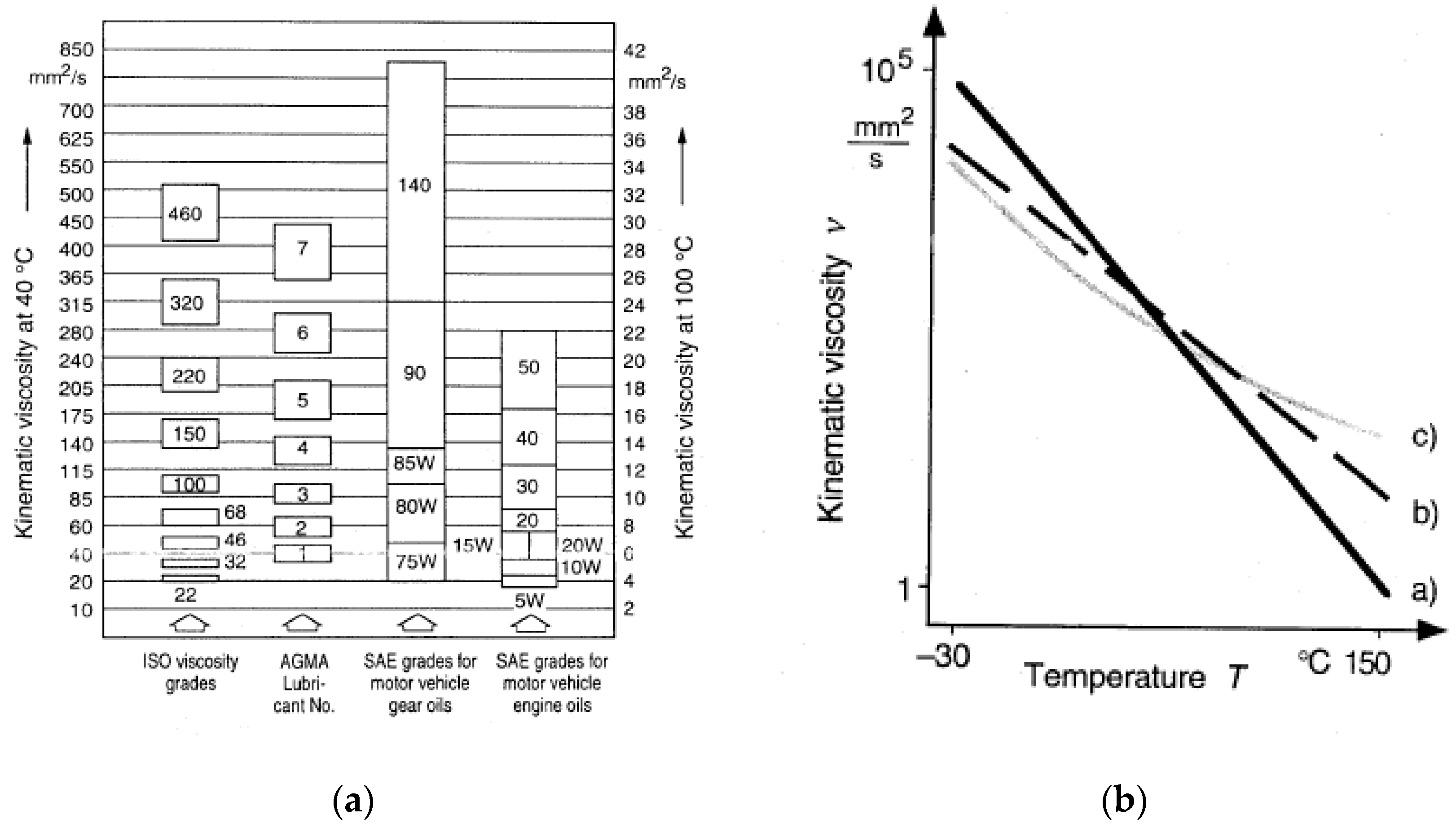
  • Oils are commonly classified, based on their V.I. (viscosity index, ISO 2909), which indicates the behavior of viscosity versus temperature: standard quality oils has V.I. = 95 to 105, whereas high quality oils has V.I. > 150;
  • If T < 20 °C or T > 110 °C, then synthetic oils have to be used;
  • Most common additives are EP (extreme pressure), AW (antiwear), V.I. (improver);
  • A compromise is needed between: (i) gear resistance to scuffing and pitting increase with viscosity (high viscosity desired); (ii) damping capacity increase with viscosity (high viscosity desired); and (iii) friction losses increase with viscosity, so that temperature also increases with viscosity (low viscosity desired).
A comparison involving some viscosity classifications (basis V.I. = 100) is shown in Figure 6a, together with the so-called Ubellohde diagram (log-log scale, Figure 6b), where viscosity versus temperature trends are displayed for different gearbox oils (a: mineral; b: Poly-α-oleofin-based; c: Polyglycol-based).
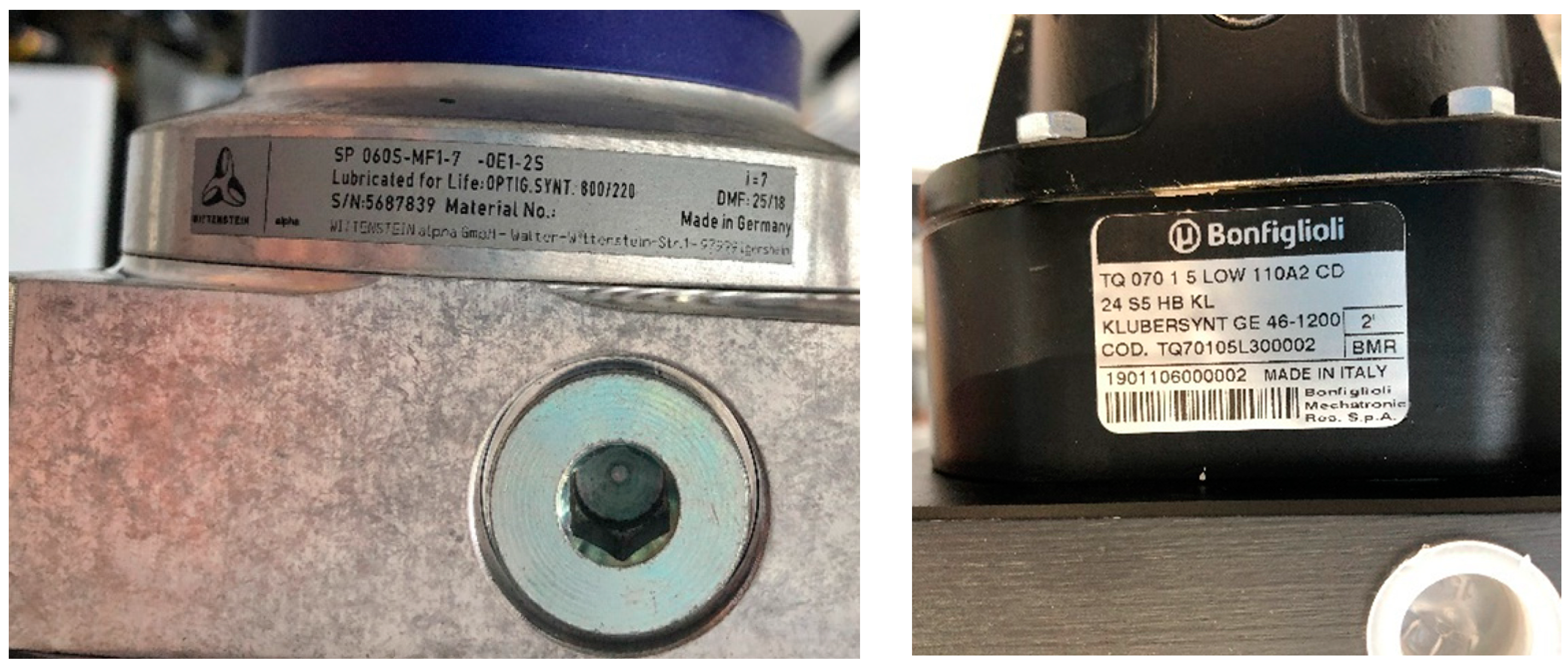
Regarding synthetic products, it is generally possible to properly select the lubricant, according to technical data provided in the datasheet in the market. Two examples of lubrication labels applied in gearboxes are shown in the following pictures of Figure 7: lubrication via synthetic oil (ISO VG 220) for gears and lubrication via synthetic long-term gear grease.

4. Gear Quality and Tolerances

Following proper module calculation and lubricant selection, as described in Section 2 and Section 3, gear designer has to select the right quality and tolerances, according to the precision grade of the gear. This operation can be done by leveraging International Standards, such as ISO1328 [52] (formerly UNI7880 [53]) or DIN3967 [54]. With regard to precision grade selection, reference can be made to Table 8, where quality class is provided, depending on the industrial application and on the linear speed v [m/s] of the gear [55].
Once the quality class has been selected, the geometrical and dimensional tolerances can be set, based on the data reported in Table 9, which reports standard tolerance intervals in agreement with Standards [52,53].
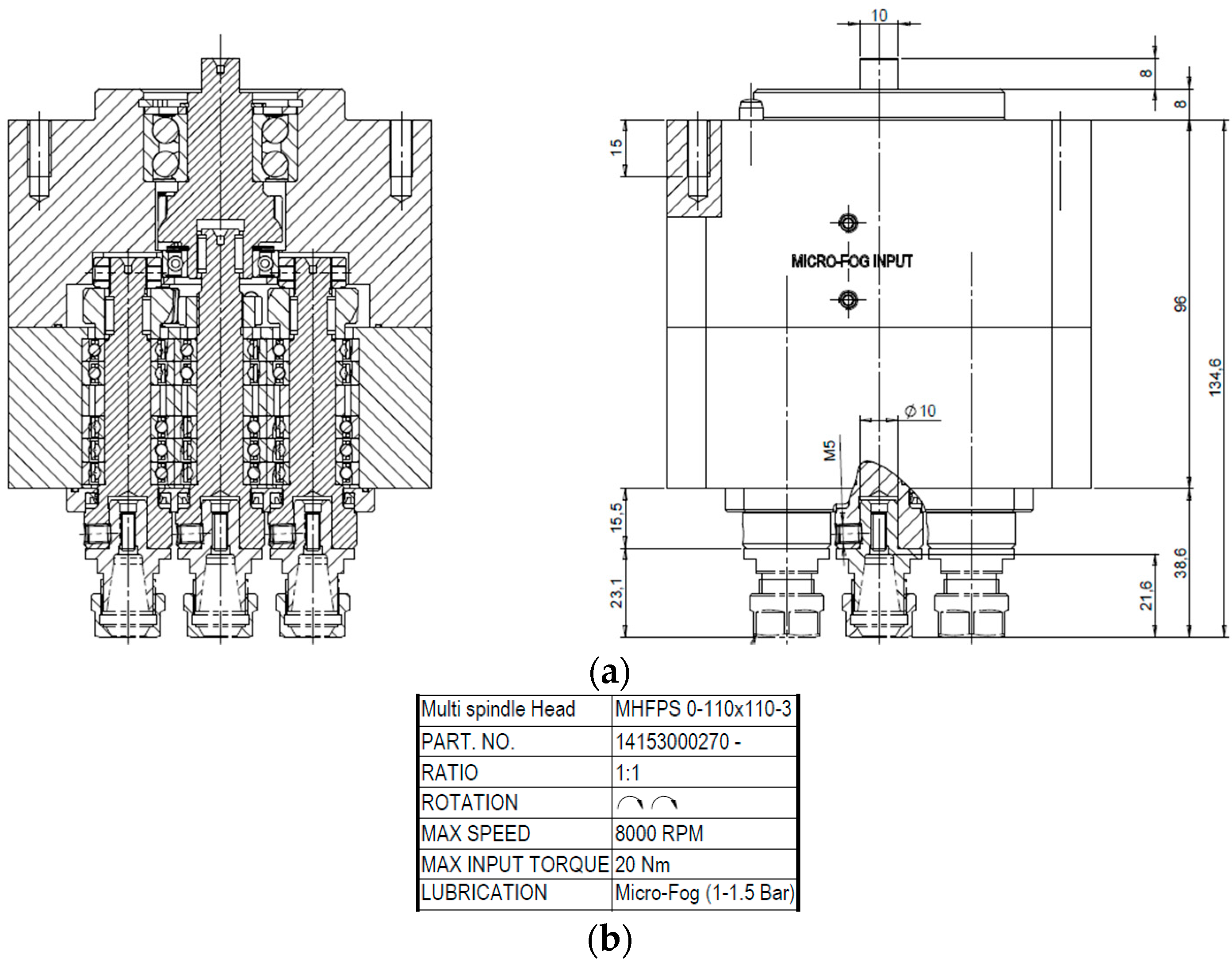
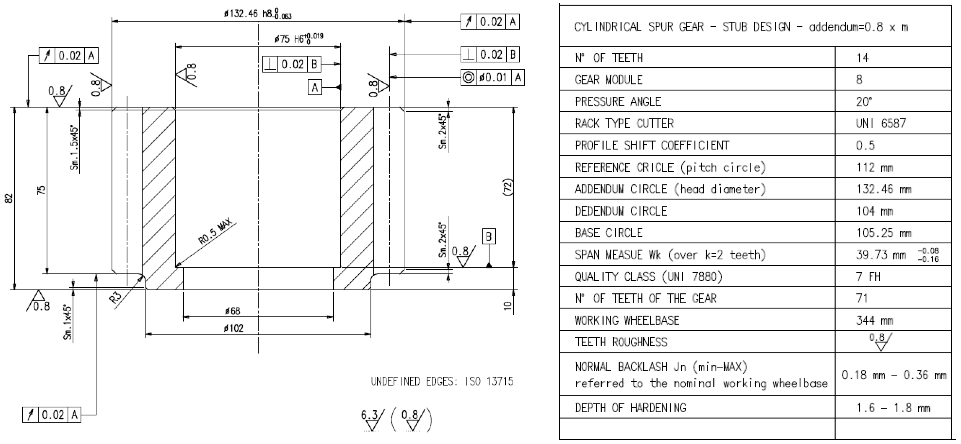
An example of pinion drawing, to be used in a rotary transfer machine, where it has the specific role of moving the main rotary table [56], is reported in Figure 8. The main features related to this industrial application are: Mt = 2.75 kNm, τ = 0.2, n = 75 rpm, theoretical wheelbase 340 mm, material: 18NiCrMo5 (hardening 58–60 HRC).
The last important parameters to be calculated and reported in the gear table are: (i) the span measurement Wk (mm) and its tolerance, and (ii) the normal backlash jn (mm) between the mating gears (referred to the nominal working wheelbase). The theoretical span measurement can be calculated by Equation (15), where the k pedix indicates the number of teeth between the measuring gauges. Its tolerance is a function of single pitch deviation fpt (μm) reported in Table 10, according to letters from C to S [52,53] (practical values between, E and L: FG, GH, or HJ suitable for generic mechanics).
{ W k = m · cos ( ϑ ) · [ ( k 0.5 ) · π + z · i n v ( θ ) + 2 · δ · tan ( ϑ ) ] k = 0.5 + z · ϑ 180 2 · δ · tan ( ϑ ) 180 .
With reference to the pinion in Figure 8, k corresponds to 2 teeth. Moreover, based on the quality class 7 (FH), the tolerance of the span measurement (Wk = 39.73 mm) ranges from Ews,1 = −4 fpt to Ewi,1 = −8 fpt (which yields the range (80 μm to 160 μm)). Finally, estimating the same values for the wheel makes it possible to estimate the normal backlash jn (mm), according to Equation (16):
{ j n _ min = ( E w s , 1 + E w s , 2 ) j n _ max = ( E w i , 1 + E w i , 2 ) .
The value of the backlash is a very important parameter since it affects both the stiffness and the lubrication condition of the mating gears [57,58].
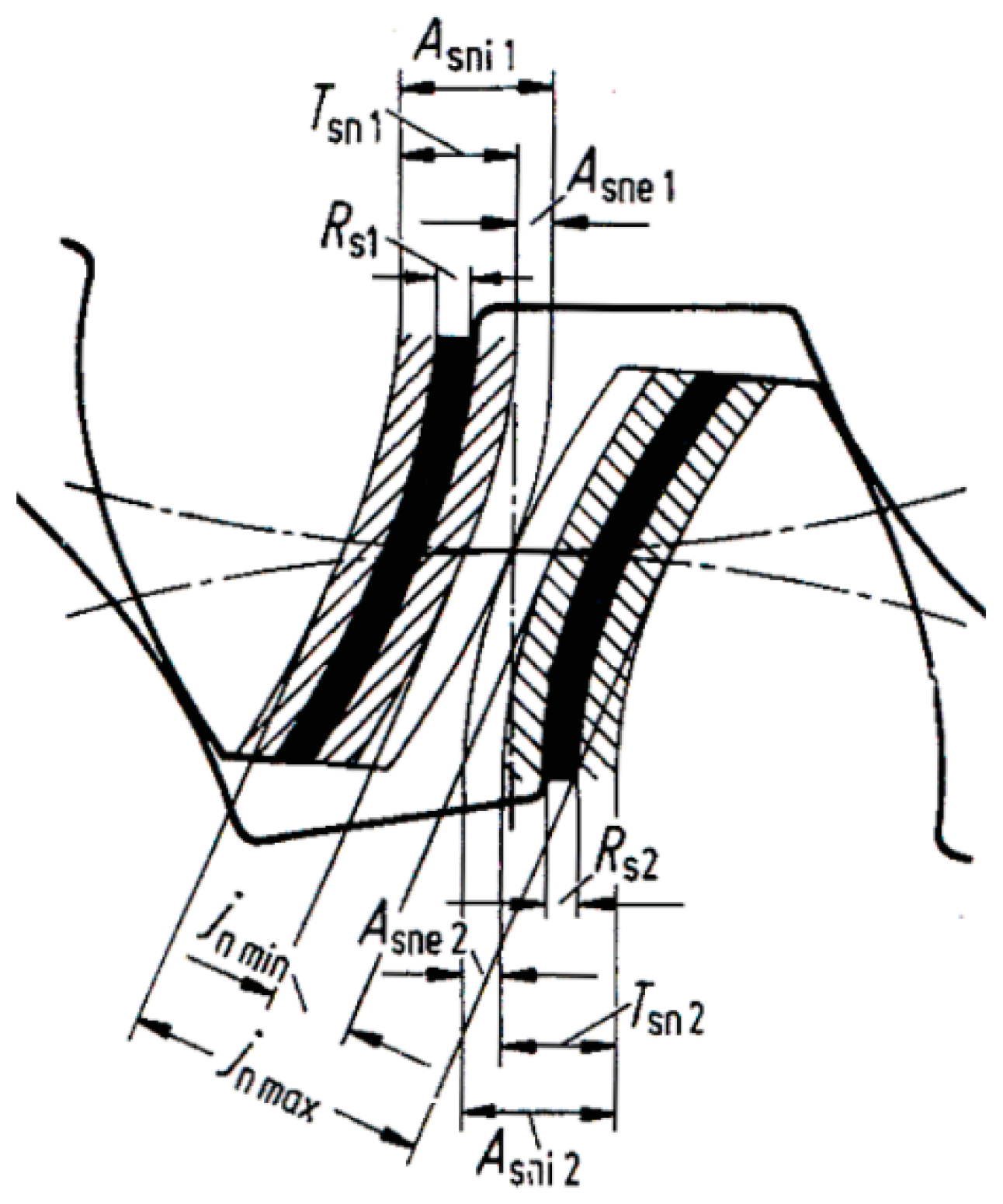
A faster way to get a rough estimation value of the backlash is provided by the following formula: jn~0.05 + 0.025·m + 0.01·v. Another option to define the tolerances is given by DIN 3967 Standard [54]: The recommended procedure can be synthetized as follows. For generic mechanical applications, it is advisable to select the group number 8, in the series within c25 and e24 (most used: cd25), according to Figure 9 and Table 11. The formula for backlash range determination (referred to the nominal working wheelbase) is available in the following Equation (17):
{ A s n i 1 - A s n e 1 = T s n 1 ; A s n i 2 - A s n e 2 = T s n 2 j n _ min = ( A s n e , 1 + A s n e , 2 ) j n _ max = ( A s n i , 1 + A s n i , 2 ) .

5. Numerical Example

In recent years, following the development of the E-mobility, the need for high power density has been more and more increased. Therefore, the goal of maximizing the transmittable power while simultaneously minimizing weight is a highly challenging task. Taking advantage of the design methodology proposed in the previous Section, an optimal solution may be easily worked out. In particular, starting from some design parameters and specifications, the optimal gear geometry can be determined. Let us consider a case study with Ii = 99 mm, τ = 0.5, λ = 10, n1 = 1500 rpm, h = 20,000 h, for a gear made of case-hardened steel. The aforementioned procedure leads to the results in Table 12 (only design against pitting is considered). The same results are also reported in Figure 10 in terms of torque-to-mass ratio: it can be highlighted that such ratio exhibits a maximum for m = 4, which is therefore the most suitable value for gear module.

6. Conclusions

A review about the practical design of gears, their tolerances, and drawings is presented in the paper in order to propose a guideline for the designer. All the proposed formula, as well as the full methodology, has been used and in-field tested for several years in the framework of gear design in the machine tool industry. The described tools may be regarded as a comprehensive method to guide the engineer from the white paper to final design and gear drawing, following the required steps for gear parameter calculation and verification. From this point of view, this paper is particularly novel, as it is a full-comprehensive collection of all the tools supporting gear design. Furthermore, the proposed method is particularly suitable for automatic computation by electronic datasheets.

Funding

This research received no external funding.

Conflicts of Interest

The authors declare no conflict of interest.

Nomenclature (Alphabetic Order)

aaddendum: (DeD)/2 [mm]
Asneminimum tooth error following the DIN3987 Standard
Asnimaximum tooth error following the DIN3987 Standard
b=λ·m: (λ = [5–50], practical range λ = [8–20]) face width [mm]
ddedendum: (DDi)/2 [mm]
Dpitch (reference) circle (diameter): 1 = input gear—pinion; 2 = output gear—wheel [mm]
Db= D·cos(ϑ): base circle [mm]
Deaddendum circle [mm]
Didedendum circle [mm]
Dmmean bearing diameter [mm]
EYoung’s modulus [MPa]
Ewimaximum tooth error
Ewsminimum tooth error
fptsingle pitch deviation [μm]
garc of action (approach + recess) on the pitch circle [mm]
= 1 2 · m · z 1 [ ( 1 + 2 · a 1 / m · z 1 cos ( ϑ ) ) 2 1 + 1 τ · ( 1 + 2 · a 2 / m · z 2 cos ( ϑ ) ) 2 1 ( 1 + 1 τ ) · tan ( ϑ ) ]
In the case of working wheelbase different from theoretical wheelbase, ϑi must be considered.
h= a + d: tooth height [mm]
hdaily hours of functioning [h]
Hdpressure limit [MPa]
I= (D1 + D2)/2 = D1(1/τ + 1)/2 = D2(1 + τ)/2: theoretical wheelbase (reference centre distance) [mm]
Iiworking wheelbase (modified center distance) [mm]
jnnormal backlash [mm]
kreduction of addendum due to profile shift
Lduty load coefficient
m= D/z: module [mm]
MtTorque moment [Nm]
nrevolutions per minute [rpm]
nrotational speed (1 = input; 2 = output) [rpm]
Q amount of oil [mm3/h]
qshape coefficient (similar to Lewis one)
t= π·m: (circular) pitch [mm]
v= ω·(D/2000): linear speed [m/s]
Wkspan measure [mm]
xprofile shifting [mm]
YLewis coefficient
znumber of teeth (1 = input; 2 = output)
εα= g/t: (transverse) contact ratio [mm]
ϑcutting pressure angle (practical value: 20°) [°]
ϑiworking pressure angle [°]
τ= z1/z2: transmission ratio
ω= 2π n/60: rotational speed (1 = input; 2 = output) [rad/s]
δprofile shifting coefficient
ηdspeed coefficient
ηElubrication coefficient
σammAdmissible strength [MPa]

Appendix A

Figure A1. Flowchart collecting all the steps for cylindrical gear design.
Lubricants 08 00084 g0a1

References

  1. Croccolo, D.; De Agostinis, M.; Vincenzi, N. Design and optimization of shaft–hub hybrid joints for lightweight structures: Analytical definition of normalizing parameters. Int. J. Mech. Sci. 2012, 56, 77–85. [Google Scholar] [CrossRef]
  2. Croccolo, D.; Vincenzi, N. On the Design of Interference-Fitted and Adhesively Bonded Joints for Lightweight Structures. J. Mech. Des. 2011, 133, 1–8. [Google Scholar] [CrossRef]
  3. Hohn, B.R.; Michaelis, K.; Otto, H.-P. Minimised gear lubrication by a minimum oil/air flow rate. Wear 2009, 266, 461–467. [Google Scholar] [CrossRef]
  4. Conrado, E.; Gorla, C.; Davoli, P.; Boniardi, M. A comparison of bending fatigue strength of carburized and nitrided gears for industrial applications. Eng. Fail. Anal. 2017, 78, 41–54. [Google Scholar] [CrossRef]
  5. Savaria, V.; Bridier, F.; Bocher, P. Predicting the effects of material properties gradient and residual stresses on the bending fatigue strength of induction hardened aeronautical gears. Int. J. Fatigue 2016, 85, 70–84. [Google Scholar] [CrossRef]
  6. Nakonieczny, A.; Monka, G. Contact fatigue strength of 41CrAlMo7 grade steel under nitriding and shot-peening treatment. Mater. Sci. 2013, 48, 715–721. [Google Scholar] [CrossRef]
  7. Meneghetti, G.; Dengo, C.; Conte, F.L. Bending fatigue design of case-hardened gears based on test specimens. Proc. IMechE Part C J. Mech. Eng. Sci. 2018, 232, 1953–1969. [Google Scholar] [CrossRef]
  8. Dengo, C.; Meneghetti, G.; Dabalà, M. Experimental analysis of bending fatigue strength of plain and notched case-hardened gear steels. Int. J. Fatigue 2015, 80, 145–161. [Google Scholar] [CrossRef]
  9. Kapelevich, A. Geometry and design of involute spur gears with asymmetric teeth. Mech. Mach. Theory 2000, 35, 117–130. [Google Scholar] [CrossRef]
  10. Costopoulos, T.; Spitas, V. Reduction of gear fillet stresses by using one-sided involute asymmetric teeth. Mech. Mach. Theory 2009, 44, 1524–1534. [Google Scholar] [CrossRef]
  11. Bonaiti, L.; Concli, F.; Gorla, C.; Rosa, F. Bending fatigue behaviour of 17-4 PH gears produced via selective laser melting. Procedia Struct. Integr. 2019, 24, 764–774. [Google Scholar] [CrossRef]
  12. Deng, G.; Nakanishi, T.; Inoue, K. Bending load capacity enhancement using an asymmetric tooth profile. JSME Int. J. Ser. C 2003, 46, 1171–1177. [Google Scholar] [CrossRef] [Green Version]
  13. Croccolo, D.; de Agostinis, M.; Fini, S.; Olmi, G.; Bogojevic, N.; Ciric-Kostic, S. Effects of build orientation and thickness of allowance on the fatigue behaviour of 15–5 PH stainless steel manufactured by DMLS. Fatigue Fract. Eng. Mater. Struct. 2018, 41, 900–916. [Google Scholar] [CrossRef] [Green Version]
  14. Politis, D.J.; Lina, J.; Dean, T.A.; Balint, D.S. An investigation into the forging of Bi-metal gears. J. Mater. Process. Technol. 2014, 214, 2248–2260. [Google Scholar] [CrossRef]
  15. Yılmaz, T.G.; Dogan, O.; Karpat, F. A comparative numerical study of forged bi-metal gears: Bending strength and dynamic response. Mech. Mach. Theory 2019, 141, 117–135. [Google Scholar] [CrossRef]
  16. ISO Standard 6336:2006. In Calculation of Load Capacity of Spur and Helical Gears; International Organization for Standardization: Geneva, Switzerland, 2006.
  17. AGMA Standard 2001–D04. In Fundamental Rating Factors and Calculation Methods for Involute Spur and Helical Gear Teeth; American Gear Manufacturers Association: Alexandria, VA, USA, 2004.
  18. Wen, Q.; Du, Q.; Zhai, X. A new analytical model to calculate the maximum tooth root stress and critical section location of spur gear. Mech. Mach. Theory 2018, 128, 275–286. [Google Scholar] [CrossRef]
  19. Dong, P.; Zuo, S.; Du, S.; Tenberge, P.; Wang, S.; Xu, X.; Wang, X. Optimum design of the tooth root profile for improving bending capacity. Mech. Mach. Theory 2020, 151, 103910. [Google Scholar] [CrossRef]
  20. Sánchez, M.B.; Pedrero, J.I.; Pleguezuelos, M. Critical stress and load conditions for bending calculations of involute spur and helical gears. Int. J. Fatigue 2013, 48, 28–38. [Google Scholar] [CrossRef]
  21. Paucker, T.; Otto, M.; Stahl, K. A precise prediction of the tooth root stresses for involute external gears with any fillet geometry under consideration of the exact meshing condition. Proc. IMechE Part C J. Mech. Eng. Sci. 2019, 233, 7318–7327. [Google Scholar] [CrossRef]
  22. Budynas, R.G.; Nisbett, J.K. Shigley’s Mechanical Engineering Design, 9th ed.; McGraw-Hill: New York, NY, USA, 2011. [Google Scholar]
  23. ISO Standard 53: 1998. In Cylindrical Gears for General and Heavy Engineering—Standard Basic Rack Tooth Profile; International Organization for Standardization: Geneva, Switzerland, 1998.
  24. ISO Standard 54: 1996. In Cylindrical Gears for General and Heavy Engineering; International Organization for Standardization: Geneva, Switzerland, 1996.
  25. Miler, D.; Loncar, A.; Žeželj, D.; Domitran, Z. Influence of profile shift on the spur gear pair optimization. Mech. Mach. Theory 2017, 117, 189–197. [Google Scholar] [CrossRef]
  26. Henriot, G. Manuale Pratico Degli Ingranaggi; Tecniche Nuove: Milan, Italy, 1993. [Google Scholar]
  27. Niemann, G.; Winter, H. Maschinenelemente; Springer: Berlin, Germany, 2005; Volume I–III. [Google Scholar]
  28. Colombo, N. Manuale Dell’ingegnere; Hoepli: Milan, Italy, 2012. [Google Scholar]
  29. Bonori, G.; Barbieri, M.; Pellicano, F. Optimum profile modifications of spur gears by means of genetic algorithms. J. Sound Vib. 2008, 313, 603–616. [Google Scholar] [CrossRef]
  30. Dowson, D.; Higginson, G.R. Elastohydrodynamic Lubrication; Pergamon: Oxford, UK, 1977. [Google Scholar]
  31. Hamrock, B.J.; Jacobson, B.O. Elastohydrodynamic lubrication of line contacts. ASLE Trans. 1984, 27, 275–287. [Google Scholar] [CrossRef]
  32. Chittenden, R.J.; Dowson, D.; Dunn, J.F.; Taylor, C.M. A theoretical analysis of the isothermal elastohydrodynamic lubrication of concentrated contacts. I. Direction of lubricant entrainment coincident with the major axis of the Hertzian contact ellipse. Proc. R. Soc. Lond. A. Math. Phys. Sci. 1985, 397, 245–269. [Google Scholar]
  33. Simon, V. EHD Lubrication of Different Types of Gears. In Advanced Tribology; Luo, J., Meng, Y., Shao, T., Zhao, Q., Eds.; Springer: Berlin/Heidelberg, Germany, 2009. [Google Scholar] [CrossRef]
  34. Liu, H.; Liu, H.; Zhu, C.; Parker, R.G. Effects of lubrication on gear performance: A review. Mech. Mach. Theory 2020, 145, 103701. [Google Scholar] [CrossRef]
  35. Lainé, E.; Olver, A.V.; Beveridge, T.A. Effect of lubricants on micropitting and wear. Tribol. Int. 2008, 41, 1049–1055. [Google Scholar] [CrossRef]
  36. Brandao, J.A.; Meheux, M.; Ville, F.; Seabra, J.H.O.; Castro, J. Comparative overview of five gear oils in mixed and boundary film lubrication. Tribol. Int. 2012, 47, 50–61. [Google Scholar] [CrossRef]
  37. Hammami, M.; Martins, R.; Abbes, M.S.; Haddar, M.; Seabrac, J. Axle gear oils: Tribological characterization under full film lubrication. Tribol. Int. 2017, 106, 109–122. [Google Scholar] [CrossRef]
  38. Sagraloff, N.; Dobler, A.; Tobie, T.; Stahl, K.; Ostrowski, J. Development of an Oil Free Water-Based Lubricant for Gear Applications. Lubricants 2019, 7, 33. [Google Scholar] [CrossRef] [Green Version]
  39. Martinsa, R.; Seabrab, J.; Britoc, A.; Seyfertd, C.; Lutherd, R.; Igartua, A. Friction coefficient in FZG gears lubricated with industrial gear oils: Biodegradable ester vs. mineral oil. Tribol. Int. 2006, 39, 512–521. [Google Scholar] [CrossRef]
  40. Kalin, M.; Vizintin, J. The tribological performance of DLC-coated gears lubricated with biodegradable oil in various pinion/gear material combinations. Wear 2005, 259, 1270–1280. [Google Scholar] [CrossRef]
  41. Gorla, C.; Concli, F.; Stahl, K.; Höhn, B.R.; Michaelis, K.; Schultheiß, H.; Stemplinger, J.P. Hydraulic losses of a gearbox: CFD analysis and experiments. Tribol. Int. 2013, 66, 337–344. [Google Scholar] [CrossRef]
  42. Liu, H.; Link, F.; Lohner, T.; Stahl, K. Computational fluid dynamics simulation of geared transmissions with injection lubrication. Proc. IMechE Part C J. Mech. Eng. Sci. 2019, 233, 7412–7422. [Google Scholar] [CrossRef]
  43. Liu, H.; Jurkschat, T.; Lohner, T.; Stahl, K. Detailed investigations on the oil flow in dip-lubricated gearboxes by the finite volume CFD method. Lubricants 2018, 6, 47. [Google Scholar] [CrossRef] [Green Version]
  44. Almqvist, T.; Larsson, R. The Navier–Stokes approach for thermal EHL line contact solutions. Tribol. Int. 2002, 35, 163–170. [Google Scholar] [CrossRef]
  45. Venner, C.H.; Napel, W.E.T. Multilevel solution of the elastohydrodynamically lubricated circular contact problem Part I: Theory and numerical algorithm. Wear 1992, 152, 351–367. [Google Scholar] [CrossRef] [Green Version]
  46. Venner, C.H.; Napel, W.E.T. Multilevel solution of the elastohydrodynamically lubricated circular contact problem Part II: Smooth surface results. Wear 1992, 152, 369–381. [Google Scholar] [CrossRef] [Green Version]
  47. Yilmaz, M.; Lohner, T.; Michaelis, K.; Stahl, K. Bearing power losses with water-containing gear fluids. Lubricants 2020, 8, 5. [Google Scholar] [CrossRef] [Green Version]
  48. Yilmaz, M.; Lohner, T.; Michaelis, K.; Stahl, K. Increasing Gearbox Efficiency by Water-Containing Fluids and Minimum Quantity Lubrication. In Proceedings of the 60th German Tribology Conference, Göttingen, Germany, 23–25 June 2019. [Google Scholar]
  49. Lechner, G.; Naunheimer, H. Automotive Transmissions; Springer: Berlin, Germany, 1999. [Google Scholar]
  50. Schaeffler Technologies AG & Co. KG: BEARINX®—Online Easy Friction—Detaillierte Reibungsberechnung von Wälzlagern; Detailled Friction Calculation of Roller Bearings; Schaeffler Technologies AG & Co: Herzogenaurach, Germany, 2011. [Google Scholar]
  51. Schaeffler Technologies AG & Co. Lubrication of Rolling Bearings–TPI 176. In Lubrication of Rotor Bearings in Wind Turbine; Schaeffler Technologies AG & Co.: Herzogenaurach, Germany, 2016. [Google Scholar]
  52. ISO Standard 1328: 2020. In Cylindrical Gears—ISO System of Flank Tolerance Classification; International Organization for Standardization: Geneva, Switzerland, 2020.
  53. UNI 7880: 1979. In Ruote Dentate—Sistema di Precisione Degli Ingranaggi Paralleli ad Evolvente; Ente Nazionale Italiano di Unificazione: Milan, Italy, 1979.
  54. DIN Standard 3967: 1978. In System of Gear Fits; Backlash, Tooth Thickness Allowances, Tooth Thickness Tolerances; Principles; DIN Standard: Berlin, Germany, 1978.
  55. DIN Standard 3961: 1978. In Tolerances for Cylindrical Gear Teeth; Bases; DIN Standard: Berlin, Germany, 1978.
  56. Croccolo, D.; de Agostinis, M.; Fini, S.; Olmi, G.; Robusto, F.; Vincenzi, N. On Hirth Ring Couplings: Design Principles Including the Effect of Friction. Actuators 2018, 7, 79. [Google Scholar] [CrossRef] [Green Version]
  57. Ren, S.; Zhang, Y.; Yang, J.; Wang, Z.; Dai, L.; Pu, W. Lubrication mechanisms of rubbing interface in internal meshing teeth with small clearance. Lubr. Sci. 2020, 32, 169–182. [Google Scholar] [CrossRef]
  58. Park, C.I. Dynamic behavior of the spur gear system with time varying stiffness by gear positions in the backlash. J. Mech. Sci. Technol. 2020, 34, 565–572. [Google Scholar] [CrossRef]
Figure 1. Example of multi-spindle head: gear and bearings lubricated by micro-fog: (a) drawing and (b) table.
Lubricants 08 00084 g001
Figure 2. Depth of hardening vs time according to Bucci Automations internal standards: (a) case hardened treatment on steel 18NiCrMo5; (b) nitriding treatment on steel 41CrAlMo7.
Lubricants 08 00084 g002
Figure 3. Example of asymmetric tooth.
Lubricants 08 00084 g003
Figure 4. Gear tooth Geometry, see Nomenclature (taken from Reference [22]).
Lubricants 08 00084 g004
Figure 5. Effect of profile shifting on tooth shape.
Lubricants 08 00084 g005
Figure 6. Mineral oil selection. Example: gear with reference diameter D = 200 mm, n = 500 rpm, working temperature of 90 °C; from (a): viscosity required at working temperature equal to ISO VG22; from (b): viscosity required at 40 °C equal to ISO VG 150.
Lubricants 08 00084 g006
Figure 7. Example of labels dedicated to lubrication in gearboxes.
Lubricants 08 00084 g007
Figure 8. Example of pinion drawing.
Lubricants 08 00084 g008
Figure 9. Definition of tooth thickness tolerances according to DIN3967 [54].
Lubricants 08 00084 g009
Figure 10. Torque/mass trend as a function of module m.
Lubricants 08 00084 g010
Table 1. Calculated values of contact ratio εα for spur gear using standard tool of 20° pressure angle according to ISO 53 [23] with no addendum modification (no profile shift).
Ii = 100 mmIi = 200 mmIi = 500 mm
z2/z1z1mεaz2/z1z1mεaz2/z1z1mεa
110011.853120011.912112541.875
5021.7551601.251.89610051.853
2541.61210021.85350101.755
2051.557802.51.8261.51602.51.909
1.58011.8495041.75510041.872
641.251.8214051.7148051.849
4021.7492581.6125081.786
322.51.70820101.55740101.749
2041.6061.516011.909312521.909
1651.5511281.251.8931002.51.893
35011.8238021.84950551.823
401.251.792642.51.82225101.714
2521.7144041.749420011.937
202.51.6713251.7081601.251.927
44011.8052081.60510021.899
321.251.77316101.550802.51.881
2021.691310011.8935041.833
162.51.6475021.8234051.805
2541.7142581.732
2051.67120101.691
10101.511
48011.881
641.251.860
4021.805
322.51.773
2041.691
1651.647
Table 2. Values of tooth factor q, according to Reference [28], for cutting pressure angle of 20° and modular (ISO 53) proportion; for stub proportion: qstub = q·0.8.
z
Number of Teeth
δ Profile Shift Coefficient [-]
−0.5−0.4−0.3−0.2−0.100.10.20.30.40.5
10******4.333.683.273.022.87
12*****4.753.843.373.062.882.79
15****4.553.93.453.152.922.782.7
20**4.854.233.763.373.122.922.762.662.6
254.94.444.043.713.413.142.982.822.692.62.55
304.133.873.643.453.243.052.892.752.642.562.52
353.833.653.453.293.122.972.822.72.62.542.49
403.683.513.343.183.042.92.772.662.572.522.47
503.473.323.173.032.912.82.692.62.532.482.44
603.343.23.072.953.832.722.642.572.52.462.42
803.143.022.922.812.72.632.572.512.462.422.39
1003.022.912.822.722.642.572.532.482.432.42.38
1502.842.762.692.622.552.52.462.432.392.372.36
* undercut: not possible.
Table 3. Values of load application factor L, according to Reference [28].
L = [1–1.25]Regular Motion—No Shocks
L = [1.25–1.5]Limited shocks
L = [1.5–1.75]Small shocks
L = [1.75–2.5]Big shocks
Table 4. Values of load sharing coefficient ε, according to Reference [28].
z ε z ε
101.25251.33
111.26301.36
121.26351.39
131.27401.42
141.27451.44
151.28501.47
161.28601.52
171.29701.58
181.29801.63
191.30901.69
201.311001.75
Table 5. Values of speed effect coefficient ƞd according to Reference [28]: (a) gears with quality grade from 6 to 8 [ƞd = 5.6/(5.6 + v0.5)]; (b) gears with quality grade from 4 to 7 (for quality grade definition, see the next section).
(a)
v [m/s]ƞd1/ƞd
50.711.40
60.701.44
70.681.47
80.661.51
90.651.54
100.641.56
110.631.59
120.621.62
(b)
v [m/s]ƞd1/ƞdv [m/s]ƞd1/ƞd
511130.831.2
611140.821.22
711150.811.24
811160.81.25
911170.791.26
1011180.791.27
1111190.781.28
1211200.771.3
Table 6. Values of lubrication condition factor ƞE, according to Reference [28].
ISO VG [cst]Engler [°]ƞE
324.50.7
4660.8
688.90.9
10013.21
15019.81.1
220291.2
32042.21.3
46060.7-
68089.8-
Table 7. Values of allowable stresses, according to Reference [28], in the case of pulsating load (for alternate load: σlim_bending ·0.7).
MaterialUltimate Stress [MPa]σlim_bending [MPa]Hd [MPa]
Cast iron180 to 26040 to 551700 to 2100
Structural steel500 to 60090 to 1001500 to 1800
Carbon steel500 to 700110 to 1401600 to 2100
Quenced and tempered steel700 to 1000135 to 2001850 to 2600
  • Surface hardened ~52 HRC: 5200;
  • Nitrided > 700 HV: 5500
Case hardening steel600 to 1200125 to 2002500
  • Surface hardened > 56 HRC: 6500
Bronze200 to 32080 to 120900 to 1200
Plastic material15035350
Table 8. ISO or DIN quality class.
123456789101112
Master gears
Precision gears—mechanical dividers
High speed gears
Gear for precise gearboxes
Gear for gearboxes
Gear for generic mechanics
Low speed gears
123456789101112
v [m/s] >20
8 … 20
3 … 8
0 … 3
Table 9. Dimensional and geometrical tolerances, according to Reference [52,53].
Tolerances on the Hub Hole Diameter, Shaft Diameter and Wheel External Diameter
Precision Grade123456789101112
HUBDiameter ToleranceIT 4IT 4IT 4IT 4IT 5IT 6IT 7IT 7IT 8IT 8IT 8IT 8
Form ToleranceIT 1IT 2IT 3
SHAFTDiameter ToleranceIT 4IT 4IT 4IT 4IT 5IT 5IT 6IT 6IT 7IT 7IT 8IT 8
Form ToleranceIT 1IT 2IT 3
Tolerance on External DiameterIT 6IT 6IT 7IT 7IT 7IT 8IT 8IT 8IT 9IT 9IT 11IT 11
Reference Surface Radial and Axial Runout Tolerance
Reference DiameterPrecision Grade
mm1 and 23 and 45 and 67 and 8from 9 to 12
OVERTORadial and axial runout in µm
-1252.87111828
1254003.69142236
4008005.012203250
80016007.018284571
1600250010.0254063100
2500400016.04063100160
Table 10. Single pitch deviation, according to Reference [52,53].
Single Pitch Deviation
Reference DiameterModulePrecision Grade
mmmm123456789101112
overtofromtofpt μm
-12513.511.62.54610142028405680
3.56.31.223.258131825365071100
6.3101.42.23.65.59142028405680112
12540013.51.11.82.84.5711162232456390
3.56.31.42.23.65.59142028405680112
6.3101.62.54610162232456390125
10161.82.84.57111825365071100140
16252.23.65.59142232456390125180
40080013.51.223.258131825365071100
3.56.31.42.23.65.59142028405680112
6.3101.82.84.57111825365071100140
101623.258132028405680112160
16252.546101625365071100140200
25403.258132032456390125180250
800160013.51.223.65.59142028405680112
3.56.31.62.54610162232456390125
6.3101.82.84.57111825365071100140
101623.258132028405680112160
16252.546101625365071100140200
25403.258132032456390125180250
1600250013.51.62.54610162232456390125
3.56.31.82.84.57111825365071100140
6.31023.258132028405680112160
10162.23.65.59142232456390125180
16252.84.57111828405680112160224
25403.65.591422365071100140200280
2500400013.51.82.84.57111825365071100140
3.56.323.258132028405680112160
6.3102.23.65.59142232456390125180
10162.546101625365071100140200
16252.84.57111828405680112160224
25403.65.591422365071100140200280
C = + 1 fptG = −6 fptL = −16 fptR = −40 fpt
D = 0H = −8 fptM = −20 fptS = −50 fpt
E = −2 fptJ = −10 fptN = −25 fpt
F = −4 fptK = −12 fptP = −32 fpt
Table 11. Tooth thickness tolerances according to DIN3967 [54].
Upper Tooth Thickness Allowance Asne in μm
Reference Diameter (mm)Allowance Series
overup toaabbbcccddefg
-10−100−85−70−58−48−40−33−22−10−5
1050−135−110−95−75−65−54−44−30−14−7
50125−180−150−125−105−85−70−60−40−19−9
125280−250−200−170−140−115−95−80−56−26−12
280560−330−280−230−190−155−130−110−75−35−17
5601000−450−370−310−260−210−175−145−100−48−22
10001600−600−500−420−340−290−240−200−135−64−30
16002500−820−680−560−460−390−320−270−180−85−41
25004000−1100−920−760−620−520−430−360−250−115−56
Tooth Thickness Tolerance Tsn in μm
Reference Diameter (mm)Allowance Series
overup to21222324252627282930
-103581220305080130200
1050581220305080130200300
5012561016254060100160250400
12528081220305080130200300500
2805601016254060100160250400600
56010001220305080130200300500800
10001600162540601001602504006001000
16002500203050801302003005008001300
2500400025406010016025040060010001600
Table 12. Numerical example of optimization.
I [mm]9997.5969999
εa [mm]1.491.461.441.661.74
m [mm]65432
Z11113162233
D1 [mm]6665646666
ƞd1.01.01.01.01.0
ƞE1.01.01.01.01.0
δ0.20.30.50.20.2
f [N0.5 mm]473453438473473
Hd [MPa]65006500650065006500
Volume [mm3]2,052,712165,915128,679102,63568,424
Mass [kg]1.611.301.010.810.54
Torque [Nm]322284236161107
Torque/Mass [Nm/kg]199.8218.1233.6199.8199.2

